EP3744983A1 - Ejector - Google Patents
Ejector Download PDFInfo
- Publication number
- EP3744983A1 EP3744983A1 EP18902421.9A EP18902421A EP3744983A1 EP 3744983 A1 EP3744983 A1 EP 3744983A1 EP 18902421 A EP18902421 A EP 18902421A EP 3744983 A1 EP3744983 A1 EP 3744983A1
- Authority
- EP
- European Patent Office
- Prior art keywords
- nozzle
- fluid
- passage
- suction
- refrigerant
- Prior art date
- Legal status (The legal status is an assumption and is not a legal conclusion. Google has not performed a legal analysis and makes no representation as to the accuracy of the status listed.)
- Withdrawn
Links
Images



Classifications
-
- F—MECHANICAL ENGINEERING; LIGHTING; HEATING; WEAPONS; BLASTING
- F04—POSITIVE - DISPLACEMENT MACHINES FOR LIQUIDS; PUMPS FOR LIQUIDS OR ELASTIC FLUIDS
- F04F—PUMPING OF FLUID BY DIRECT CONTACT OF ANOTHER FLUID OR BY USING INERTIA OF FLUID TO BE PUMPED; SIPHONS
- F04F5/00—Jet pumps, i.e. devices in which flow is induced by pressure drop caused by velocity of another fluid flow
- F04F5/44—Component parts, details, or accessories not provided for in, or of interest apart from, groups F04F5/02 - F04F5/42
- F04F5/46—Arrangements of nozzles
-
- F—MECHANICAL ENGINEERING; LIGHTING; HEATING; WEAPONS; BLASTING
- F04—POSITIVE - DISPLACEMENT MACHINES FOR LIQUIDS; PUMPS FOR LIQUIDS OR ELASTIC FLUIDS
- F04F—PUMPING OF FLUID BY DIRECT CONTACT OF ANOTHER FLUID OR BY USING INERTIA OF FLUID TO BE PUMPED; SIPHONS
- F04F5/00—Jet pumps, i.e. devices in which flow is induced by pressure drop caused by velocity of another fluid flow
- F04F5/14—Jet pumps, i.e. devices in which flow is induced by pressure drop caused by velocity of another fluid flow the inducing fluid being elastic fluid
- F04F5/16—Jet pumps, i.e. devices in which flow is induced by pressure drop caused by velocity of another fluid flow the inducing fluid being elastic fluid displacing elastic fluids
-
- F—MECHANICAL ENGINEERING; LIGHTING; HEATING; WEAPONS; BLASTING
- F25—REFRIGERATION OR COOLING; COMBINED HEATING AND REFRIGERATION SYSTEMS; HEAT PUMP SYSTEMS; MANUFACTURE OR STORAGE OF ICE; LIQUEFACTION SOLIDIFICATION OF GASES
- F25B—REFRIGERATION MACHINES, PLANTS OR SYSTEMS; COMBINED HEATING AND REFRIGERATION SYSTEMS; HEAT PUMP SYSTEMS
- F25B1/00—Compression machines, plants or systems with non-reversible cycle
Definitions
- the present disclosure relates to an ejector configured to draw a fluid by an entrainment effect of a high-speed fluid ejected from a nozzle.
- a general ejector is configured to draw a fluid through a fluid suction port formed in a body by an entrainment effect of a high-speed fluid ejected from a nozzle.
- energy loss caused when a refrigerant is decompressed by the nozzle is recovered by drawing the fluid from the outside.
- a pressure of a mixture of the jet fluid and a suction fluid is increased by converting the recovered energy into a pressure energy by a diffuser portion (i.e. pressure increase portion).
- Patent Literature 1 discloses an ejector used in a supercritical refrigeration cycle in which carbon dioxide is used as a refrigerant and the pressure of the refrigerant on a high-pressure side of the cycle exceeds a critical pressure of the refrigerant.
- the ejector functions as a refrigerant decompressor.
- the ejector of Patent Literature 1 includes a plug nozzle as a nozzle.
- the plug nozzle is a nozzle used with a needle that is disposed in a nozzle passage defined in the nozzle such that the fluid is ejected along the needle.
- it is attempted to improve the energy conversion efficiency in the nozzle by bringing the expansion form of the jet fluid close to the proper form regardless of the pressure fluctuation of the refrigerant flowing into the nozzle.
- Patent Literature 2 discloses an ejector including a suction passage to reduce the energy loss of the fluid flowing through the ejector.
- a suction passage is defined between an outer surface of a nozzle and an inner surface of a cylindrical body to which the nozzle is fixed.
- a part of the body defining the suction passage is a curved surface such that the flow directions of the suction fluid and the jet fluid are aligned with each other.
- the suction passage is defined between the outer surface of the nozzle and the inner surface of the body, the flow directions of the suction fluid and the jet fluid may not be appropriately aligned with each other if the outer surface of the nozzle is not formed in an appropriate shape even if the part of the body defining the suction passage is the curved surface as in Patent Literature 2.
- a nozzle passage defined in the Laval nozzle includes: a converging portion that decreases the passage cross-sectional area toward the downstream side of the fluid flow; a throat portion provided at the most downstream part of the converging portion in the fluid flow, the passage cross-sectional area at the throat portion being the smallest in the nozzle; and a diverging portion that increases the passage cross-sectional area from the throat portion toward the fluid injection port. Accordingly, since the length of the nozzle in a direction along the central axis is relatively long, the shape of the outer surface of the nozzle can be easily processed into a desired shape such that the suction fluid flows along the central axis.
- the throat portion is located at the most downstream portion of the nozzle passage to bring the expansion form of the jet fluid close to the proper expansion. Accordingly, the nozzle passage of an ideal plug nozzle may not have a passage corresponding to the diverging portion of the Laval nozzle.
- the length of the fluid passage in the direction along the central axis may be equal to or shorter than twice a diameter of an opening of the fluid injection port. Further, the inventors have confirmed through tests and studies that, by forming the nozzle such that the length of the fluid passage in the direction along the central axis is equal to or shorter than twice the diameter of the opening of the injection port, the energy conversion efficiency by the nozzle is equal to or higher than that by an ideal nozzle.
- an ejector including a nozzle having a throat portion at most downstream part of a nozzle passage which can reduce energy loss caused in a fluid flowing through the ejector without increasing a size of the ejector.
- An ejector includes a body and a nozzle configured to decompress a fluid and eject the fluid from a fluid injection port.
- the body has a fluid suction port, a mixing portion, and a pressure increase portion.
- the fluid is drawn into the body through the fluid suction port by an entrainment effect of a jet fluid ejected from the fluid injection port.
- the jet fluid and a suction fluid drawn through the fluid suction port is mixed in the mixing portion.
- the pressure increase portion is configured to convert a velocity energy of the mixed fluid flowing out of the mixing portion into a pressure energy. At least a part of the nozzle is housed in the body.
- a suction passage through which the suction fluid flows is defined between an outer surface of the nozzle and an inner surface of the body.
- the mixing portion has a shape of a solid of revolution about a central axis of the nozzle.
- a nozzle passage defined in the nozzle includes: a converging portion decreasing a passage cross-sectional area toward a downstream side of a fluid flow; and a throat portion located at most downstream part of the converging portion, the passage cross-sectional area at the throat portion being smallest in the nozzle passage.
- a length of a part of the nozzle passage extending from the throat portion to the fluid injection port in a direction along the central axis is equal to or less than twice a diameter of an opening of the fluid injection port.
- a reference cross-section is a cross-section including the central axis.
- a part of the outer surface of the nozzle defining the suction passage approaches the central axis toward the downstream side of the fluid flow.
- a nozzle outer periphery intersection point is an intersection point of the central axis and a nozzle outer periphery line passing through a largest diameter point and a smallest diameter point of the part of the outer surface of the nozzle defining the suction passage, a diameter of the part of the outer surface of the nozzle being largest at the largest diameter point and being smallest at the smallest diameter point.
- the nozzle outer periphery intersection point is located inside the mixing portion.
- the nozzle outer periphery intersection point is located inside the mixing portion.
- the suction fluid flowing along the outer surface of the nozzle can be guided to the inside of the mixing portion to merge with the jet fluid inside the mixing portion.
- the energy loss caused when the suction fluid and the jet fluid are mixed can be suppressed.
- the length of the part of the outer surface of the nozzle defining the suction passage in the direction along the central axis can be short compared with a case where the nozzle outer periphery intersection point is located downstream of the mixing portion.
- the energy loss caused in the fluid flowing through the ejector can be suppressed.
- the sentence "the length of the fluid passage extending from the throat portion to the fluid injection port in the direction along the central axis is equal to or less than twice the diameter of the opening of the fluid injection port” includes a meaning that the length of the fluid passage in the direction along the central axis is 0, i.e. the fluid passage extending from the throat portion to the fluid injection portion is not defined. However, when a diverging portion is provided as the fluid passage extending from the throat portion to the fluid injection port, a length of the diverging portion in the direction along the central axis is greater than 0.
- An ejector includes a body and a nozzle configured to decompress a fluid and eject the fluid from a fluid injection port.
- the body has a fluid suction port, a mixing portion, and a pressure increase portion.
- the fluid is drawn into the body through the fluid suction port by an entrainment effect of a jet fluid ejected from the fluid injection port.
- the jet fluid and a suction fluid drawn through the fluid suction port is mixed in the mixing portion.
- the pressure increase portion is configured to convert a velocity energy of the mixed fluid flowing out of the mixing portion into a pressure energy. At least a part of the nozzle is housed in the body.
- a suction passage through which the suction fluid flows is defined between an outer surface of the nozzle and an inner surface of the body.
- the mixing portion has a shape of a solid of revolution about a central axis of the nozzle.
- a nozzle passage defined in the nozzle includes: a converging portion decreasing a passage cross-sectional area toward a downstream side of a fluid flow; a throat portion located at most downstream part of the converging portion, the passage cross-sectional area at the throat portion being smallest in the nozzle passage; and a diverging portion increasing the passage cross-sectional area from the throat portion to the fluid injection port.
- a length of the diverging portion in a direction along the central axis is equal to or less than twice a diameter of an opening of the fluid injection port.
- a reference cross-section is a cross-section including the central axis.
- a nozzle inner periphery line passes through a smallest diameter point of the diverging portion at which a diameter of the diverging portion is smallest and a largest diameter point of the diverging portion at which the diameter of the diverging portion is largest, and the nozzle inner periphery line intersects with the mixing portion of the body.
- the nozzle inner periphery line intersects with the mixing portion of the body.
- the jet fluid flowing along the inner surface of the diverging portion can be guided to the inside of the mixing portion to merge with the jet fluid inside the mixing portion.
- the energy loss caused when the suction fluid and the jet fluid are mixed can be suppressed.
- the length of the diverging portion in the direction along the central axis is equal to or less than the diameter of the opening of the fluid injection port, the length of the part of the outer surface of the nozzle defining the suction passage in the direction along the central axis can be limited from increasing.
- the energy loss caused in the fluid flowing through the ejector can be suppressed.
- an ejector 14 according to the present embodiment is applied to an ejector refrigeration cycle 10 which is a vapor compression type refrigeration cycle device.
- the ejector refrigeration cycle 10 has a function of heating the water in a heat pump for supplying the water stored in a tank to a kitchen, bath, or the like as residential water.
- the water is a heat exchange target fluid of the ejector refrigeration cycle 10.
- the fluid to be ejected, suctioned, or increased in pressure by the ejector 14 is a refrigerant of the ejector refrigeration cycle 10.
- the refrigerant of the ejector refrigeration cycle 10 is carbon dioxide.
- the ejector refrigeration cycle 10 constitutes a supercritical refrigeration cycle in which the pressure of the refrigerant discharged from a compressor 11 (i.e. the refrigerant on the high-pressure side in the cycle) is equal to or higher than the critical pressure of the refrigerant. Accordingly, the ejector refrigeration cycle 10 can heat the water such that the temperature of the water is equal to or higher than 90 degrees Celsius.
- the compressor 11 of the ejector refrigeration cycle 10 is configured to draw the refrigerant, pressurize the refrigerant to be high-pressure refrigerant, and discharge the refrigerant.
- the compressor 11 is an electric compressor in which a fixed displacement compression mechanism whose discharge capacity is fixed is driven by an electric motor.
- the rotation speed (i.e. the refrigerant discharge capacity) of the compressor 11 is controlled according to a control signal output from a controller (not shown).
- a refrigerant inlet side of a water-refrigerant heat exchanger 12 is connected to a refrigerant discharge port of the compressor 11.
- the water-refrigerant heat exchanger 12 is a radiator configured to radiate heat of the high-pressure refrigerant discharged from the compressor 11 to the water circulating in a water circulating cycle 20.
- the water-refrigerant heat exchanger 12 serves as a heating heat exchanger for heating the water.
- a water pump for pumping the water, a tank for storing the heated water (not shown), and the like are disposed in the water circulating cycle 20.
- An outlet side of the water-refrigerant heat exchanger 12 is connected to an inlet side of an electric expansion valve 13.
- the electric expansion valve 13 is a variable throttle mechanism configured to decompress the high-pressure refrigerant flowing out of the water-refrigerant heat exchanger 12 to be an intermediate-pressure refrigerant.
- the electric expansion valve 13 also functions as a flow rate adjuster for adjusting the flow rate of the refrigerant flowing to the downstream side.
- the throttle degree of the electric expansion valve 13 is controlled according to a control signal output from the controller.
- An outlet of the electric expansion valve 13 is connected to an inlet side of a nozzle 41 of the ejector 14.
- the ejector 14 is a refrigerant decompressor configured to decompress the intermediate-pressure refrigerant flowing out of the electric expansion valve 13 to a low-pressure refrigerant. Further, the ejector 14 functions as a refrigerant transport device that draws and transports the refrigerant that has flowed out of an evaporator 16, which will be described later, by the entrainment effect of the jet refrigerant ejected from the nozzle 41 at a high speed.
- the detailed configuration of the ejector 14 will be described with reference to FIGS. 2 and 3 .
- the ejector 14 has the nozzle 41 and a body 42.
- the nozzle 41 is configured to convert the pressure energy of the refrigerant flowing therein from an inlet 41a into a velocity energy.
- the nozzle 41 is configured to decompress the refrigerant flowing therein from the inlet 41a in an isentropic manner, and effect the refrigerant from a refrigerant injection port 41e located at the most downstream part in the refrigerant flow.
- the nozzle 41 is made of a substantially cylindrical metal (in the present embodiment, a stainless steel alloy) whose tip portion tapers in the flow direction of the refrigerant.
- a nozzle passage defined in the nozzle 41 has a converging portion 41b, a throat portion 41c, and the like.
- the cross-sectional area of the converging portion 41b decreases from the inlet 41a side toward the downstream side of the refrigerant flow.
- the throat portion 41c is formed at the most downstream part of the converging portion 41b in the refrigerant flow.
- the passage cross-sectional area is the smallest at the throat portion 41c.
- a refrigerant passage 41d is defined between the throat portion 41c and the refrigerant injection port 41e for convenience in manufacturing.
- the cross-sectional area of the refrigerant passage 41d is equal to that of the throat portion 41c. Therefore, the energy loss due to friction generated when the refrigerant flows through the refrigerant passage 41d tends to be relatively large. Accordingly, in an ideal nozzle 41, it is desirable that the throat portion 41c and the refrigerant injection port 41e coincide with each other without form ing the refrigerant passage 41d. However, forming the throat portion 41c and the refrigerant injection port 41e to coincide with each other with high accuracy may cause an increase in manufacturing cost, for example.
- the nozzle 41 of the present embodiment has the refrigerant passage 41d
- an outer peripheral portion of the refrigerant injection port 41e of the nozzle 41 (that is, the tip of the nozzle 41) is chamfered, for example.
- a length of the refrigerant passage 41d in a direction along a central axis CL of the nozzle 41 is equal to or less than twice a diameter ⁇ D of an opening of the refrigerant injection port 41e. Accordingly, the nozzle 41 of the present embodiment has the throat portion 41c at the most downstream part of the nozzle passage.
- the inventors have confirmed through tests and studies that, by forming the nozzle 41 such that the length of the refrigerant passage 41d in the axial direction is equal to or less than twice the diameter of the refrigerant injection port, the energy conversion efficiency by the nozzle 41 is equal to or higher than that by an ideal nozzle in which the throat portion 41c and the refrigerant injection port 41e coincide with each other.
- the shape of the nozzle 41 can be close to an ideal shape as much as possible.
- a chamfered part of the tip portion of the nozzle 41 is so small that the chamfered part does not affect the performance of the ejector 14. Accordingly, the chamfered part of the tip portion of the nozzle 41 is not included in a part of the outer peripheral surface of the nozzle 41 defining the suction passage 42c.
- the body 42 is made of a substantially cylindrical metal (aluminum in the present embodiment).
- the body 42 functions as a fixation member for supporting the nozzle 41 and forms a framework of the ejector 14.
- the nozzle 41 is fixed by press-fitting or the like so as to be accommodated inside the one end side in the longitudinal direction of the body 42.
- a refrigerant suction port 42a is provided in a portion of the outer peripheral surface of the body 42 on the outer peripheral side of the nozzle 41 so as to penetrate the inside and the outside of the portion and communicate with the refrigerant injection port 41e of the nozzle 41.
- the refrigerant suction port 42a is a through-hole that draws in the refrigerant flowing out of the evaporator 16 into the ejector 14 by using entrainment effect of the jet refrigerant discharged from the refrigerant injection port 41e of the nozzle 41.
- a mixing portion 42b, the suction passage 42c, and a diffuser portion 42d are formed in the body 34.
- the mixing portion 42b defines a space for mixing the jet refrigerant ejected from the refrigerant injection port 41e with the suction refrigerant drawn from the refrigerant suction port 42a.
- the mixing portion 42b has a circular column shape of a sold of revolution.
- the mixing portion 42b is located downstream of the nozzle 41 in the refrigerant flow.
- the center axis of the mixing portion 42b is disposed coaxially with the central axis CL of the nozzle 41.
- the suction passage 42c is a refrigerant passage for guiding the suction refrigerant drawn from the refrigerant suction port 42a to the mixing portion 42b.
- the suction passage 42c is a space defined by the outer surface of the tapered tip portion of the nozzle 41 and the inner surface of the body 42. Accordingly, the cross-section of the suction passage 42c taken along a plane perpendicular to the central axis CL has an annular shape. Further, the refrigerant outlet of the suction passage 42c has an annular shape surrounding the refrigerant injection port 41e.
- the diffuser portion 42d defines a space for converting the velocity energy of the mixed refrigerant of the jet refrigerant and the suction refrigerant into the pressure energy. That is, the diffuser portion 42d is a pressure increase portion that slows down the flow speed of the mixed refrigerant to increase the pressure of the mixed refrigerant.
- the diffuser portion 42d defines a space that continues from the outlet of the mixing portion 42b and increases the passage cross-sectional area toward the downstream side of the refrigerant flow.
- the diffuser portion 42d is formed in a substantially truncated conical shape of revolution.
- the center axis of the diffuser portion 42d is disposed coaxially with the central axis CL of the nozzle 41.
- FIGS. 2 , 3 are cross-sectional diagrams illustrating the reference cross-section of the ejector 14 taken along the axial direction.
- a line representing the outer surface of the nozzle 41 defining the suction passage 42c approaches the central axis CL toward the downstream side of the refrigerant flow. Further, a line representing the inner surface of the body 42 defining the suction passage 42c approaches the central axis CL toward the downstream of the refrigerant flow. Accordingly, the passage cross-sectional area of the suction passage 42c decreases toward the downstream side of the refrigerant flow.
- a line passing through a largest diameter point Pmx1 and a smallest diameter point Pmn1 is defined as a nozzle outer periphery line L1.
- the largest diameter point Pmx1 is a part of the outer surface of the nozzle 41 at which the diameter of the nozzle 41 is the largest in the part defining the suction passage 42c.
- the smallest diameter point Pmn1 is a part of the outer surface of the nozzle 41 at which the diameter of the nozzle 41 is the smallest in the part defining the suction passage 42c.
- An intersection point at which the nozzle outer periphery line L1 intersects with the central axis CL is defined as a nozzle outer periphery intersection point P1.
- the nozzle outer periphery line L1 intersects with a line representing the mixing portion 42b. Further, in the reference cross-section, the nozzle outer periphery intersection point P1 is located inside the mixing portion 42b. That is, the nozzle outer periphery intersection point P1 is located downstream of an inlet portion of the mixing portion 42b in the refrigerant flow.
- a line passing through a largest diameter point Pmx2 and a smallest diameter point Pmn2 is defined as a body inner periphery line L2.
- the largest diameter point Pmx2 is a part of the inner surface of the body 42 at which the diameter of the body 42 is the largest in the part defining the suction passage 42c.
- the smallest diameter point Pmn2 is a part of the inner surface of the body 42 at which the diameter of the body 42 is the smallest in the part defining the suction passage 42c.
- An intersection point at which the body inner periphery line L2 intersects with the nozzle outer periphery line L1 is defined as a suction passage intersection point P2.
- the suction passage intersection point P2 is located inside the mixing portion 42b and on the central axis CL. That is, the suction passage intersection point P2 is located on a part of the central axis CL that is located downstream of the inlet portion of the mixing portion 42b in the refrigerant flow. Accordingly, in the present embodiment, in the reference cross-section, the nozzle outer periphery intersection point P1 coincides with the suction passage intersection point P2.
- a refrigerant outlet of the diffuser portion 42d is connected to an inlet side of an accumulator 15.
- the accumulator 15 is a gas-liquid separation unit that separates gas and liquid of the refrigerant that has flowed out of the diffuser portion 42d from each other.
- the accumulator 15 according to the present embodiment also functions as a reservoir for storing a part of the separated liquid-phase refrigerant as an excess refrigerant in the cycle.
- a gas-phase refrigerant outlet port of the accumulator 15 is connected to the intake port side of the compressor 11.
- the liquid-phase refrigerant outlet port of the accumulator 15 is connected to the refrigerant inlet side of the evaporator 16 through a fixed throttle 15a that is a decompression portion.
- a fixed throttle 15a an orifice, a capillary tube, or the like can be employed.
- the evaporator 16 is a heat-absorbing heat exchanger that evaporates the low-pressure refrigerant and exerts a heat absorbing action by exchanging heat between the low-pressure refrigerant reduced in pressure by the fixed throttle 15a and the air blown from the outside fan 16a.
- the refrigerant outlet of the evaporator 16 is connected to the refrigerant suction port 42a of the ejector 14.
- the outside fan 16a is an electric blower whose rotation speed (i.e., blowing capacity) is controlled by a control voltage output from the controller.
- the controller (not shown) is configured by a well-known microcomputer including a CPU, a ROM, a RAM, and the like, and peripheral circuits of the microcomputer.
- the controller performs various calculations and processes based on a control program stored in the ROM.
- the controller controls the electric actuators 11, 13, 16a connected to the output side of the controller.
- a sensor group including multiple control sensors such as an outside air temperature sensor, a high-pressure sensor, and a water temperature sensor is connected to the controller.
- the detection values of the sensors are input to the controller.
- the outside air temperature sensor is an outside air temperature detection unit that detects the outside air temperature.
- the high-pressure sensor is a high-pressure refrigerant pressure detection unit configured to detect the pressure of the high-pressure refrigerant flowing out of the water-refrigerant heat exchanger 12.
- the tank temperature sensor is a water temperature detection unit configured to detect the temperature of the water stored in the tank.
- an operation panel located in the house is connected to the input side of the controller. Operation signals output from various operation switches on the operation panel are input to the controller.
- the operation switches on the operation panel includes an actuation switch for actuating the heat pump type water heater, a temperature adjustment switch for adjusting the temperature of the water stored in the tank, and the like.
- the controller integrally includes control units that control operation of various control target devices connected to an output side of the controller.
- the controller includes a configuration (hardware and software) that controls operation of each of the control target devices and embodies a control unit of the corresponding control target device.
- the configuration for controlling the refrigerant discharge capacity of the compressor 11 constitutes the discharge capacity control unit.
- the controller actuates the compressor 11, the electric expansion valve 13, the outside fan 16a, and the like.
- the compressor 11 draws the refrigerant, compresses the refrigerant, and discharges the refrigerant.
- the high-temperature high-pressure refrigerant discharged from the compressor 11 flows into the refrigerant passage in the water-refrigerant heat exchanger 12 and exchanges heat with the water circulating in the water circulating cycle 20.
- the heated water is stored in the tank connected to the water circulating cycle 20.
- the rotational speed (i.e. the refrigerant discharge capacity) of the compressor 11 is determined with reference to a control map preliminarily stored in the controller based on the detection value of the outside air temperature sensor.
- the refrigerant flowing out of the refrigerant passage in the water-refrigerant heat exchanger 12 is decompressed by the electric expansion valve 13 to become the intermediate-pressure refrigerant.
- the throttle degree of the electric expansion valve 13 is determined with reference to a control map preliminarily stored in the controller based on the detection value of the high-pressure sensor and the like. In this control map, the throttle degree of the electric expansion valve 13 is determined such that the coefficient of performance (COP) of the cycle approaches the maximum value.
- COP coefficient of performance
- the intermediate-pressure refrigerant decompressed by the electric expansion valve 13 flows into the nozzle 41 of the ejector 14 through the inlet 41a.
- the refrigerant flowing into the nozzle 41 of the ejector 14 is isentropically decompressed and ejected from the refrigerant injection port 41e.
- the refrigerant flowing out of the evaporator 16 is drawn from the refrigerant suction port 42a by the entrainment effect of the jet refrigerant ejected from the refrigerant injection port 41e of the nozzle 41.
- the suction refrigerant drawn from the refrigerant suction port 42a flows into the mixing portion 42b through the suction passage 42c and is mixed with the jet refrigerant.
- the refrigerant mixed in the mixing portion 42b flows into the diffuser portion 42d.
- a kinetic energy of the mixed refrigerant is converted into a pressure energy since the passage cross-sectional area increases.
- the pressure of the mixture refrigerant rises.
- the refrigerant flowing out of the diffuser portion 42d flows into the accumulator 15 and is separated into gas and liquid.
- the liquid-phase refrigerant separated by the accumulator 15 is reduced in pressure by the fixed throttle 15a and flows into the evaporator 16.
- the refrigerant flowing into the evaporator 16 absorbs heat from the outside air blown from the outside fan 16a and evaporates.
- the refrigerant flowing out of the evaporator 16 is drawn into the ejector 14 through the refrigerant suction port 42a.
- the gas-phase refrigerant separated by the accumulator 15 is drawn into the compressor 11 and compressed again.
- the ejector refrigeration cycle 10 of the present embodiment operates as described above, and accordingly the water stored in the tank of the heat pump type water heater is heated.
- the refrigerant increased in pressure by the diffuser portion 42d of the ejector 14 is drawn into the compressor 11.
- the ejector refrigeration cycle 10 can thus achieve reduction of power consumption of the compressor 11 and improvement in coefficient of performance (COP) of the cycle, in comparison with a general refrigeration cycle device having refrigerant evaporating pressure at an evaporator substantially equal to pressure of a refrigerant drawn into a compressor.
- COP coefficient of performance
- the nozzle outer periphery intersection point P1 is located downstream of the inlet portion of the mixing portion 42b. Accordingly, the pressure increase amount in the diffuser portion 42d is greater than a general ejector, and the COP of the ejector refrigeration cycle 10 can be improved.
- the nozzle outer periphery intersection point P1 is located inside the mixing portion 42b in the reference cross-section as shown in FIG. 3 . Accordingly, an angle between the flow direction of the mainstream of the suction fluid and the flow direction of the mainstream of the jet fluid can be reduced without increase of the size of the ejector 14, and the energy loss can be reduced.
- the suction refrigerant and the jet refrigerant are mixed at a part located upstream of the mixing portion 42b. This may cause turbulence in the mixed refrigerant before flowing into the mixing portion 42b, and the turbulence may cause vortices. As a result, friction between the mixed refrigerant and the wall surface defining the suction passage 42c may cause an increase of the energy loss of the refrigerant.
- the nozzle outer periphery intersection point P1 is located downstream of the mixing portion 42b in the refrigerant flow, the angle between the flow direction of the mainstream of the suction fluid and the flow direction of the mainstream of the jet fluid is decreased, and accordingly the energy loss can be reduced.
- a length of the part of the nozzle 41 defining the suction passage 42c is elongated in the direction along the central axis CL. Accordingly, this may result in increase of size of the ejector 14 as a whole.
- the nozzle outer periphery intersection point P1 is located inside the mixing portion 42b, the suction fluid flowing along the outer surface of the nozzle 41 can be guided to the inside of the mixing portion 42b such that the suction fluid is mixed with the jet fluid inside the mixing portion 42b. Accordingly, the increase of the energy loss due to mixing of the suction fluid and the jet fluid at the part located upstream of the mixing portion 42b can be suppressed. Further, the length of the nozzle 41 in the direction along the central axis CL does not unnecessarily increase.
- the energy loss of the refrigerant flowing through the ejector 14 can be reduced without increasing the size of the ejector 14.
- the pressure increase amount by the ejector 14 can be increased, and the COP of the ejector refrigeration cycle 10 including the ejector 14 can be improved.
- the nozzle 41 has the throat portion 41c at the most downstream part of the nozzle passage. Accordingly, the energy loss due to the friction caused when the refrigerant flows through the part located downstream of the throat portion 41c can be suppressed. As a result, the energy loss caused when the refrigerant flowing through the ejector can be further suppressed.
- the nozzle outer periphery line L1 intersects with a line representing the mixing portion 42b of the body 42. According to this, the nozzle outer periphery intersection point P1 is surely located inside the mixing portion 42b.
- the suction passage intersection point P2 is located inside the mixing portion 42b and on the central axis CL. According to this, the suction fluid flowing along the inner surface of the body 42 can be guided to the inside of the mixing portion 42b to be mixed with the jet fluid inside the mixing portion 42b. As a result, the energy loss caused when the suction fluid and the jet fluid are mixed can be further suppressed.
- the suction passage intersection point P2 is located on the central axis CL and coincides with the nozzle outer periphery intersection point P1.
- the suction passage intersection point P2 may be modified to be located as shown in FIGS. 4 , 5 , as long as the suction passage intersection point P2 is located inside the mixing portion 42b.
- FIGS. 4 , 5 are drawings corresponding to FIG. 3 .
- the suction passage intersection point P2 is located inside the mixing portion 42b and over the central axis CL in the reference cross-section. That is, the suction passage intersection point P2 is located downstream of the intersection point of the body inner periphery line L2 and the central axis CL. According to this, the angle between the flow direction of the mainstream of the suction fluid and the flow direction of the mainstream of the jet fluid is decreased, and the energy loss can be suppressed.
- the suction passage intersection point P2 is located inside the mixing portion 42b and at a position that does not exceed the central axis CL in the reference cross-section. That is, the suction passage intersection point P2 is located upstream of the intersection point of the body inner periphery line L2 and the central axis CL. According to this, since the angle between the flow direction of the mainstream of the suction fluid and the flow direction of the mainstream of the jet fluid is increased, the mixability of the suction fluid and the jet fluid can be improved.
- the position of the suction passage intersection point P2 may be appropriately modified based on the priority of the effect of suppressing the energy loss and the effect of improving the mixability of the suction fluid and the jet fluid.
- the advantages of the ejector 14 of the present embodiment i.e. the effect of reducing the energy loss of the refrigerant flowing through the ejector 14 without increasing the size, is effective in an ejector in which the shape of the outer surface of the nozzle 41 defining the suction passage 42c is likely to affect the flow direction of the suction fluid.
- Such ejectors include, for example, a small ejector in which the passage cross-sectional area of the suction passage 42c or the passage cross-sectional area of the mixing portion 42b is relatively small, an ejector in which the outer diameter of the nozzle 41 is nearly equal to the inner diameter of the part of the body 42 defining the mixing portion 42b, and an ejector in which the length from the refrigerant injection port 41e to the inlet of the mixing portion 42b is relatively small (for example, the length is less than 5 times the inner diameter of the mixing portion 42b).
- FIG. 6 is a drawing corresponding to FIG. 3 described in the first embodiment.
- the same or equivalent parts as those of the first embodiment are denoted by the same reference numerals.
- the nozzle passage of the present embodiment includes a diverging portion 41g in which the passage cross-sectional area increases from the throat portion 41c toward the refrigerant injection port 41e. Further, the length of the diverging portion 41g in the direction along the central axis CL is equal to or less than twice the diameter ⁇ D of the opening of the refrigerant injection port 41e. Accordingly, the nozzle 41 of the present embodiment has the throat portion 41c at the most downstream part of the nozzle passage.
- a line passing through a smallest diameter point Pmn3 and a largest diameter point Pmx3 is defined as a nozzle inner periphery line L3.
- the smallest diameter point Pmn3 is a part of the diverging portion 41g at which the diameter of the diverging portion 41g is the smallest.
- the largest diameter point Pmx3 is a part of the diverging portion 41g at which the diameter of the diverging portion 41g is the largest.
- a part at which the nozzle inner periphery line L3 intersects with the nozzle outer periphery line L1 is defined as a nozzle shape intersection point P3.
- the nozzle inner periphery line L3 intersects with the line representing the mixing portion 42b. Further, the nozzle shape intersection point P3 is located inside the mixing portion 42b. That is, the nozzle shape intersection point P3 is located downstream of an inlet portion of the mixing portion 42b in the refrigerant flow.
- Other configurations and operations of the ejector 14 and the ejector refrigeration cycle 10 are the same as those of the first embodiment.
- the ejector refrigeration cycle 10 of the present embodiment can heat the water stored in the tank of the heat pump type water heater as in the first embodiment. Moreover, according to the ejector 14 of the present embodiment, the energy loss of the refrigerant flowing through the ejector 14 can be reduced without increasing the size of the ejector 14 as in the first embodiment.
- the nozzle inner periphery line L3 intersects with a line representing the mixing portion 42b of the body 42. According to this, since the jet fluid flowing along the inner surface of the diverging portion 41g can be guided to the inside of the mixing portion 42b to be mixed with the suction fluid inside the mixing portion 42b, the energy loss caused when the suction fluid and the jet fluid are mixed can be suppressed.
- the length of the diverging portion 41g in the direction along the central axis CL is not longer than twice the diameter ⁇ D of the opening of the refrigerant injection port 41e, the length of the nozzle in the central axis CL is not unnecessarily increased.
- the suction fluid flowing along the inner surface of the body 42 can be guided to the inside of the mixing portion 42b such that the suction fluid is mixed with the jet fluid inside the mixing portion 42b.
- the energy loss caused when the suction fluid and the jet fluid are mixed can be further suppressed.
- the advantages of the shape of the diverging portion 41g of the ejector 14 according to the present embodiment i.e. the effect of reducing the energy loss of the refrigerant flowing through the ejector 14 without increasing the size, is effective in an ejector in which the shape of the outer surface of the nozzle 41 defining the suction passage 42c is likely to affect the flow direction of the suction fluid.
- Such ejectors include, for example, a small ejector in which the passage cross-sectional area of the suction passage 42c or the passage cross-sectional area of the mixing portion 42b is relatively small, and an ejector in which the length from the refrigerant injection port 41e to the inlet of the mixing portion 42b is relatively small (for example, the length is less than 5 times the inner diameter of the mixing portion 42b).
- the ejector 14 of the present disclosure is used in the ejector refrigeration cycle 10.
- the usage of the ejector 14 of the present disclosure is not limited to this.
- the ejector 14 may be used in devices other than the ejector refrigeration cycle.
- the usage of the ejector refrigeration cycle 10 is not limited to the heat pump type water heater.
- the ejector refrigeration cycle 10 may be used for: an air-conditioning device for adjusting the temperature of the air that is a heat exchange target fluid and is conveyed to an air-conditioning target space; and a refrigeration container for cooling an air that is a heat exchange target fluid and circulating in a refrigeration space, for example.
- the ejector refrigeration cycle may include a branch portion 17 configured to branch the flow of the refrigerant flowing out of the refrigerant passage in the water-refrigerant heat exchanger 12, and a second evaporator 18 configured to evaporate the refrigerant flowing out of the ejector 14.
- one refrigerant outlet of the branch portion 17 may be connected to the inlet 41a of the ejector 14, the other one refrigerant outlet of the branch portion 17 may be connected to the refrigerant inlet side of the first evaporator 16 through the fixed throttle 15a, and the outlet of the diffuser portion 42d of the ejector 14 may be connected to the intake port side of the compressor 11 through the second evaporator 18.
- the configuration of the ejector 14 is not limited to that disclosed in the embodiments described above.
- the refrigerant passage 41d is defined in the ejector 14.
- the ejector 14 may not have the refrigerant passage 41d and the chamfered portion of the tip portion of the nozzle 41 if it can be manufactured.
- the line representing the outer surface of the nozzle 41 defining the suction passage 42c is a linear line. However, this line is not limited to be linear and may be a curved line. Similarly, in the above-described embodiments, the line representing the inner surface of the body 42 defining the suction passage 42c is a linear line. However, this line is not limited to be linear and may be a curved line.
- the mixing portion 42b has a circular column shape.
- the mixing portion 42b may have a truncated conical shape increasing the passage cross-sectional area toward the downstream side of the refrigerant flow, like the diffuser portion 42d.
- a spread angle (that is, an increasing degree of the passage cross-sectional area) of the mixing portion 42b is set to be smaller than a spread angle (that is, an increasing degree of the passage cross-sectional area) of the diffuser portion 42d.
- the line representing the diffuser portion 42d of the body 42 in the reference cross-section may be a combination of multiple curves.
- the increasing degree of the passage cross-sectional area of the diffuser portion 42d may decrease after gradually increasing along the flow direction of the fluid.
- the pressure of the fluid can be isentropically increased in the diffuser portion 42d.
- the electric expansion valve 13 is used.
- the ejector 14 may further have a valuable mechanism for adjusting the flow rate.
- a needle-shaped valve body may be disposed in the nozzle passage of the nozzle 41.
- a central axis of the valve body is disposed coaxially with the central axis CL of the nozzle 41.
- an actuation device e.g. stepper motor for displacing the valve body in the direction along the central axis CL is disposed in the body 42.
- the passage cross-sectional area at the throat portion 41c can be changed by moving the valve body using the actuation device.
- the ejector 14 has a function of a flow rate adjuster.
- the needle-shaped valve body may be arranged to stick out from the refrigerant injection port 41e toward the downstream side of the refrigerant flow regardless of the presence or absence of the actuation device. According to this, the expansion form of the jet refrigerant can be approximated to a proper expansion, and the energy conversion efficiency by the nozzle 41 that is a plug nozzle can be further improved.
- the components described in each of the above embodiments may be appropriately combined to the extent practicable.
- the position of the suction passage intersection point P2 may be changed as described in the modification example of the first embodiment.
Landscapes
- Engineering & Computer Science (AREA)
- Physics & Mathematics (AREA)
- Fluid Mechanics (AREA)
- Mechanical Engineering (AREA)
- General Engineering & Computer Science (AREA)
- Jet Pumps And Other Pumps (AREA)
Abstract
Description
- This application is based on Japanese Patent Application No.
2018-009477 filed on January 24, 2018 - The present disclosure relates to an ejector configured to draw a fluid by an entrainment effect of a high-speed fluid ejected from a nozzle.
- Conventionally, a general ejector is configured to draw a fluid through a fluid suction port formed in a body by an entrainment effect of a high-speed fluid ejected from a nozzle. In this type of ejector, energy loss caused when a refrigerant is decompressed by the nozzle is recovered by drawing the fluid from the outside. A pressure of a mixture of the jet fluid and a suction fluid is increased by converting the recovered energy into a pressure energy by a diffuser portion (i.e. pressure increase portion).
- For example, Patent Literature 1 discloses an ejector used in a supercritical refrigeration cycle in which carbon dioxide is used as a refrigerant and the pressure of the refrigerant on a high-pressure side of the cycle exceeds a critical pressure of the refrigerant. The ejector functions as a refrigerant decompressor.
- The ejector of Patent Literature 1 includes a plug nozzle as a nozzle. The plug nozzle is a nozzle used with a needle that is disposed in a nozzle passage defined in the nozzle such that the fluid is ejected along the needle. In the ejector of Patent Literature 1, by adopting the plug nozzle, it is attempted to improve the energy conversion efficiency in the nozzle by bringing the expansion form of the jet fluid close to the proper form regardless of the pressure fluctuation of the refrigerant flowing into the nozzle.
- Patent Literature 2 discloses an ejector including a suction passage to reduce the energy loss of the fluid flowing through the ejector.
- In a general ejector, a suction passage is defined between an outer surface of a nozzle and an inner surface of a cylindrical body to which the nozzle is fixed. In the ejector of Patent Literature 2, a part of the body defining the suction passage is a curved surface such that the flow directions of the suction fluid and the jet fluid are aligned with each other. As a result, according to the ejector of Patent Literature 2, it is attempted to reduce the energy loss (i.e. mixing loss) caused when the suction fluid and the jet fluid are mixed.
-
- Patent Literature 1:
JP 2004-270460 A - Patent Literature 2:
US Patent Application Publication No. 2016/0187037 - Since the suction passage is defined between the outer surface of the nozzle and the inner surface of the body, the flow directions of the suction fluid and the jet fluid may not be appropriately aligned with each other if the outer surface of the nozzle is not formed in an appropriate shape even if the part of the body defining the suction passage is the curved surface as in Patent Literature 2.
- In view of this point, since a Laval nozzle is used as the nozzle in Patent Literature 2, the outer surface of the nozzle can be easily formed into an appropriate shape.
- A nozzle passage defined in the Laval nozzle includes: a converging portion that decreases the passage cross-sectional area toward the downstream side of the fluid flow; a throat portion provided at the most downstream part of the converging portion in the fluid flow, the passage cross-sectional area at the throat portion being the smallest in the nozzle; and a diverging portion that increases the passage cross-sectional area from the throat portion toward the fluid injection port. Accordingly, since the length of the nozzle in a direction along the central axis is relatively long, the shape of the outer surface of the nozzle can be easily processed into a desired shape such that the suction fluid flows along the central axis.
- In the plug nozzle, the throat portion is located at the most downstream portion of the nozzle passage to bring the expansion form of the jet fluid close to the proper expansion. Accordingly, the nozzle passage of an ideal plug nozzle may not have a passage corresponding to the diverging portion of the Laval nozzle.
- Even if a fluid passage is formed at a part located downstream of the throat portion for the convenience of manufacturing, the length of the fluid passage in the direction along the central axis may be equal to or shorter than twice a diameter of an opening of the fluid injection port. Further, the inventors have confirmed through tests and studies that, by forming the nozzle such that the length of the fluid passage in the direction along the central axis is equal to or shorter than twice the diameter of the opening of the injection port, the energy conversion efficiency by the nozzle is equal to or higher than that by an ideal nozzle.
- In the ejector having the plug nozzle as in Patent Literature 1, it may be difficult to process the outer surface of the downstream part of the nozzle into an appropriate shape, and accordingly it may be difficult to form the suction passage to decrease the energy loss. It may be conceivable that the size of the nozzle is increased to process the shape of the outer surface of the nozzle into an appropriate shape. However, this may lead to an increase of the size of the ejector.
- In view of the above points, it is an object of the present disclosure to provide an ejector including a nozzle having a throat portion at most downstream part of a nozzle passage which can reduce energy loss caused in a fluid flowing through the ejector without increasing a size of the ejector.
- An ejector according to a first aspect of the present disclosure includes a body and a nozzle configured to decompress a fluid and eject the fluid from a fluid injection port. The body has a fluid suction port, a mixing portion, and a pressure increase portion. The fluid is drawn into the body through the fluid suction port by an entrainment effect of a jet fluid ejected from the fluid injection port. The jet fluid and a suction fluid drawn through the fluid suction port is mixed in the mixing portion. The pressure increase portion is configured to convert a velocity energy of the mixed fluid flowing out of the mixing portion into a pressure energy. At least a part of the nozzle is housed in the body. A suction passage through which the suction fluid flows is defined between an outer surface of the nozzle and an inner surface of the body. The mixing portion has a shape of a solid of revolution about a central axis of the nozzle. A nozzle passage defined in the nozzle includes: a converging portion decreasing a passage cross-sectional area toward a downstream side of a fluid flow; and a throat portion located at most downstream part of the converging portion, the passage cross-sectional area at the throat portion being smallest in the nozzle passage. A length of a part of the nozzle passage extending from the throat portion to the fluid injection port in a direction along the central axis is equal to or less than twice a diameter of an opening of the fluid injection port. A reference cross-section is a cross-section including the central axis. In the reference cross-section, a part of the outer surface of the nozzle defining the suction passage approaches the central axis toward the downstream side of the fluid flow. In the reference cross-section, a nozzle outer periphery intersection point is an intersection point of the central axis and a nozzle outer periphery line passing through a largest diameter point and a smallest diameter point of the part of the outer surface of the nozzle defining the suction passage, a diameter of the part of the outer surface of the nozzle being largest at the largest diameter point and being smallest at the smallest diameter point. The nozzle outer periphery intersection point is located inside the mixing portion.
- According to this, in the reference cross-section of the ejector having the nozzle in which the length of the fluid passage from the throat portion to the fluid injection port is equal to or less than twice the diameter of the opening of the fluid injection port, i.e. in the reference cross-section of the ejector having the nozzle in which the throat portion is located at the most downstream part of the nozzle passage, the nozzle outer periphery intersection point is located inside the mixing portion.
- Accordingly, the suction fluid flowing along the outer surface of the nozzle can be guided to the inside of the mixing portion to merge with the jet fluid inside the mixing portion. As a result, the energy loss caused when the suction fluid and the jet fluid are mixed can be suppressed.
- Further, the length of the part of the outer surface of the nozzle defining the suction passage in the direction along the central axis can be short compared with a case where the nozzle outer periphery intersection point is located downstream of the mixing portion.
- That is, according to the ejector of the first aspect, in the ejector having the nozzle in which the throat portion is located at the most downstream part of the nozzle passage, the energy loss caused in the fluid flowing through the ejector can be suppressed.
- The sentence "the length of the fluid passage extending from the throat portion to the fluid injection port in the direction along the central axis is equal to or less than twice the diameter of the opening of the fluid injection port" includes a meaning that the length of the fluid passage in the direction along the central axis is 0, i.e. the fluid passage extending from the throat portion to the fluid injection portion is not defined. However, when a diverging portion is provided as the fluid passage extending from the throat portion to the fluid injection port, a length of the diverging portion in the direction along the central axis is greater than 0.
- An ejector according to a second aspect of the present disclosure includes a body and a nozzle configured to decompress a fluid and eject the fluid from a fluid injection port. The body has a fluid suction port, a mixing portion, and a pressure increase portion. The fluid is drawn into the body through the fluid suction port by an entrainment effect of a jet fluid ejected from the fluid injection port. The jet fluid and a suction fluid drawn through the fluid suction port is mixed in the mixing portion. The pressure increase portion is configured to convert a velocity energy of the mixed fluid flowing out of the mixing portion into a pressure energy. At least a part of the nozzle is housed in the body. A suction passage through which the suction fluid flows is defined between an outer surface of the nozzle and an inner surface of the body. The mixing portion has a shape of a solid of revolution about a central axis of the nozzle. A nozzle passage defined in the nozzle includes: a converging portion decreasing a passage cross-sectional area toward a downstream side of a fluid flow; a throat portion located at most downstream part of the converging portion, the passage cross-sectional area at the throat portion being smallest in the nozzle passage; and a diverging portion increasing the passage cross-sectional area from the throat portion to the fluid injection port. A length of the diverging portion in a direction along the central axis is equal to or less than twice a diameter of an opening of the fluid injection port. A reference cross-section is a cross-section including the central axis. In the reference cross-section, a nozzle inner periphery line passes through a smallest diameter point of the diverging portion at which a diameter of the diverging portion is smallest and a largest diameter point of the diverging portion at which the diameter of the diverging portion is largest, and the nozzle inner periphery line intersects with the mixing portion of the body.
- According to this, in the reference cross-section of the ejector having the nozzle in which the length of the diverging portion in the direction along the central axis is equal to or less than twice the diameter of the opening of the fluid injection port, i.e. in the reference cross-section of the ejector having the nozzle in which the throat portion is located at the most downstream part of the nozzle passage, the nozzle inner periphery line intersects with the mixing portion of the body.
- Accordingly, the jet fluid flowing along the inner surface of the diverging portion can be guided to the inside of the mixing portion to merge with the jet fluid inside the mixing portion. As a result, the energy loss caused when the suction fluid and the jet fluid are mixed can be suppressed.
- Further, since the length of the diverging portion in the direction along the central axis is equal to or less than the diameter of the opening of the fluid injection port, the length of the part of the outer surface of the nozzle defining the suction passage in the direction along the central axis can be limited from increasing.
- That is, according to the ejector of the second aspect, in the ejector having the nozzle in which the throat portion is located at the most downstream part of the nozzle passage, the energy loss caused in the fluid flowing through the ejector can be suppressed.
-
-
FIG. 1 is a diagram illustrating an ejector refrigeration circuit as a whole in a first embodiment. -
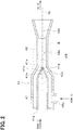
FIG. 2 is a cross-sectional diagram of the ejector taken along an axial direction according to the first embodiment. -
FIG. 3 is a schematic enlarged view of a part III ofFIG. 2 . -
FIG. 4 is a schematic enlarged cross-sectional diagram showing a modification example of the ejector according to the first embodiment. -
FIG. 5 is a schematic enlarged cross-sectional diagram illustrating another modification example of the ejector according to the first embodiment. -
FIG. 6 is a schematic enlarged cross-sectional diagram illustrating an ejector according to a second embodiment. -
FIG. 7 is a diagram of an ejector refrigeration circuit as a whole in another embodiment. - Hereinafter, embodiments for implementing the present disclosure will be described referring to drawings. In each embodiment, portions corresponding to the elements described in the preceding embodiments are denoted by the same reference numerals, and redundant explanation may be omitted. When only a part of a configuration is described in an embodiment, another preceding embodiment may be applied to the other parts of the configuration. The present disclosure is not limited to combinations of embodiments which combine parts that are explicitly described as being combinable. As long as no problem is present, the various embodiments may be partially combined with each other even if not explicitly described.
- A first embodiment of the present disclosure will be described with reference to
FIGS. 1 to 5 . As shown inFIG. 1 , anejector 14 according to the present embodiment is applied to anejector refrigeration cycle 10 which is a vapor compression type refrigeration cycle device. Theejector refrigeration cycle 10 has a function of heating the water in a heat pump for supplying the water stored in a tank to a kitchen, bath, or the like as residential water. - Accordingly, the water is a heat exchange target fluid of the
ejector refrigeration cycle 10. The fluid to be ejected, suctioned, or increased in pressure by theejector 14 is a refrigerant of theejector refrigeration cycle 10. - The refrigerant of the
ejector refrigeration cycle 10 is carbon dioxide. Theejector refrigeration cycle 10 constitutes a supercritical refrigeration cycle in which the pressure of the refrigerant discharged from a compressor 11 (i.e. the refrigerant on the high-pressure side in the cycle) is equal to or higher than the critical pressure of the refrigerant. Accordingly, theejector refrigeration cycle 10 can heat the water such that the temperature of the water is equal to or higher than 90 degrees Celsius. - The
compressor 11 of theejector refrigeration cycle 10 is configured to draw the refrigerant, pressurize the refrigerant to be high-pressure refrigerant, and discharge the refrigerant. In the present embodiment, thecompressor 11 is an electric compressor in which a fixed displacement compression mechanism whose discharge capacity is fixed is driven by an electric motor. The rotation speed (i.e. the refrigerant discharge capacity) of thecompressor 11 is controlled according to a control signal output from a controller (not shown). - A refrigerant inlet side of a water-
refrigerant heat exchanger 12 is connected to a refrigerant discharge port of thecompressor 11. The water-refrigerant heat exchanger 12 is a radiator configured to radiate heat of the high-pressure refrigerant discharged from thecompressor 11 to the water circulating in awater circulating cycle 20. The water-refrigerant heat exchanger 12 serves as a heating heat exchanger for heating the water. A water pump for pumping the water, a tank for storing the heated water (not shown), and the like are disposed in thewater circulating cycle 20. - An outlet side of the water-
refrigerant heat exchanger 12 is connected to an inlet side of anelectric expansion valve 13. Theelectric expansion valve 13 is a variable throttle mechanism configured to decompress the high-pressure refrigerant flowing out of the water-refrigerant heat exchanger 12 to be an intermediate-pressure refrigerant. Theelectric expansion valve 13 also functions as a flow rate adjuster for adjusting the flow rate of the refrigerant flowing to the downstream side. The throttle degree of theelectric expansion valve 13 is controlled according to a control signal output from the controller. - An outlet of the
electric expansion valve 13 is connected to an inlet side of anozzle 41 of theejector 14. Theejector 14 is a refrigerant decompressor configured to decompress the intermediate-pressure refrigerant flowing out of theelectric expansion valve 13 to a low-pressure refrigerant. Further, theejector 14 functions as a refrigerant transport device that draws and transports the refrigerant that has flowed out of anevaporator 16, which will be described later, by the entrainment effect of the jet refrigerant ejected from thenozzle 41 at a high speed. - The detailed configuration of the
ejector 14 will be described with reference toFIGS. 2 and3 . Theejector 14 has thenozzle 41 and abody 42. - The
nozzle 41 is configured to convert the pressure energy of the refrigerant flowing therein from aninlet 41a into a velocity energy. Thenozzle 41 is configured to decompress the refrigerant flowing therein from theinlet 41a in an isentropic manner, and effect the refrigerant from arefrigerant injection port 41e located at the most downstream part in the refrigerant flow. Thenozzle 41 is made of a substantially cylindrical metal (in the present embodiment, a stainless steel alloy) whose tip portion tapers in the flow direction of the refrigerant. - A nozzle passage defined in the
nozzle 41 has a convergingportion 41b, athroat portion 41c, and the like. The cross-sectional area of the convergingportion 41b decreases from theinlet 41a side toward the downstream side of the refrigerant flow. Thethroat portion 41c is formed at the most downstream part of the convergingportion 41b in the refrigerant flow. The passage cross-sectional area is the smallest at thethroat portion 41c. Further, in thenozzle 41, arefrigerant passage 41d is defined between thethroat portion 41c and therefrigerant injection port 41e for convenience in manufacturing. - The cross-sectional area of the
refrigerant passage 41d is equal to that of thethroat portion 41c. Therefore, the energy loss due to friction generated when the refrigerant flows through therefrigerant passage 41d tends to be relatively large. Accordingly, in anideal nozzle 41, it is desirable that thethroat portion 41c and therefrigerant injection port 41e coincide with each other without form ing therefrigerant passage 41d. However, forming thethroat portion 41c and therefrigerant injection port 41e to coincide with each other with high accuracy may cause an increase in manufacturing cost, for example. - Thus, although the
nozzle 41 of the present embodiment has therefrigerant passage 41d, an outer peripheral portion of therefrigerant injection port 41e of the nozzle 41 (that is, the tip of the nozzle 41) is chamfered, for example. A length of therefrigerant passage 41d in a direction along a central axis CL of thenozzle 41 is equal to or less than twice a diameter ϕD of an opening of therefrigerant injection port 41e. Accordingly, thenozzle 41 of the present embodiment has thethroat portion 41c at the most downstream part of the nozzle passage. - The inventors have confirmed through tests and studies that, by forming the
nozzle 41 such that the length of therefrigerant passage 41d in the axial direction is equal to or less than twice the diameter of the refrigerant injection port, the energy conversion efficiency by thenozzle 41 is equal to or higher than that by an ideal nozzle in which thethroat portion 41c and therefrigerant injection port 41e coincide with each other. - That is, by forming the
nozzle 41 such that the length of the part defining therefrigerant passage 41d in the direction along the central axis CL is equal to or less than twice the diameter ϕD of the opening of therefrigerant injection port 41e, the shape of thenozzle 41 can be close to an ideal shape as much as possible. - Further, a chamfered part of the tip portion of the
nozzle 41 is so small that the chamfered part does not affect the performance of theejector 14. Accordingly, the chamfered part of the tip portion of thenozzle 41 is not included in a part of the outer peripheral surface of thenozzle 41 defining thesuction passage 42c. - The
body 42 is made of a substantially cylindrical metal (aluminum in the present embodiment). Thebody 42 functions as a fixation member for supporting thenozzle 41 and forms a framework of theejector 14. Specifically, thenozzle 41 is fixed by press-fitting or the like so as to be accommodated inside the one end side in the longitudinal direction of thebody 42. - A
refrigerant suction port 42a is provided in a portion of the outer peripheral surface of thebody 42 on the outer peripheral side of thenozzle 41 so as to penetrate the inside and the outside of the portion and communicate with therefrigerant injection port 41e of thenozzle 41. Therefrigerant suction port 42a is a through-hole that draws in the refrigerant flowing out of theevaporator 16 into theejector 14 by using entrainment effect of the jet refrigerant discharged from therefrigerant injection port 41e of thenozzle 41. - Further, a mixing
portion 42b, thesuction passage 42c, and adiffuser portion 42d are formed in the body 34. The mixingportion 42b defines a space for mixing the jet refrigerant ejected from therefrigerant injection port 41e with the suction refrigerant drawn from therefrigerant suction port 42a. The mixingportion 42b has a circular column shape of a sold of revolution. The mixingportion 42b is located downstream of thenozzle 41 in the refrigerant flow. The center axis of the mixingportion 42b is disposed coaxially with the central axis CL of thenozzle 41. - The
suction passage 42c is a refrigerant passage for guiding the suction refrigerant drawn from therefrigerant suction port 42a to the mixingportion 42b. Thesuction passage 42c is a space defined by the outer surface of the tapered tip portion of thenozzle 41 and the inner surface of thebody 42. Accordingly, the cross-section of thesuction passage 42c taken along a plane perpendicular to the central axis CL has an annular shape. Further, the refrigerant outlet of thesuction passage 42c has an annular shape surrounding therefrigerant injection port 41e. - The
diffuser portion 42d defines a space for converting the velocity energy of the mixed refrigerant of the jet refrigerant and the suction refrigerant into the pressure energy. That is, thediffuser portion 42d is a pressure increase portion that slows down the flow speed of the mixed refrigerant to increase the pressure of the mixed refrigerant. - The
diffuser portion 42d defines a space that continues from the outlet of the mixingportion 42b and increases the passage cross-sectional area toward the downstream side of the refrigerant flow. Thediffuser portion 42d is formed in a substantially truncated conical shape of revolution. The center axis of thediffuser portion 42d is disposed coaxially with the central axis CL of thenozzle 41. - Next, the detailed shapes of the
nozzle 41 and thebody 42 of theejector 14 will be described with reference toFIG. 3 . First, a cross-section of the nozzle including the central axis CL is defined as a reference cross-section. Accordingly,FIGS. 2 ,3 are cross-sectional diagrams illustrating the reference cross-section of theejector 14 taken along the axial direction. - As shown in
FIG. 3 , in the present embodiment, a line representing the outer surface of thenozzle 41 defining thesuction passage 42c approaches the central axis CL toward the downstream side of the refrigerant flow. Further, a line representing the inner surface of thebody 42 defining thesuction passage 42c approaches the central axis CL toward the downstream of the refrigerant flow. Accordingly, the passage cross-sectional area of thesuction passage 42c decreases toward the downstream side of the refrigerant flow. - A line passing through a largest diameter point Pmx1 and a smallest diameter point Pmn1 is defined as a nozzle outer periphery line L1. The largest diameter point Pmx1 is a part of the outer surface of the
nozzle 41 at which the diameter of thenozzle 41 is the largest in the part defining thesuction passage 42c. The smallest diameter point Pmn1 is a part of the outer surface of thenozzle 41 at which the diameter of thenozzle 41 is the smallest in the part defining thesuction passage 42c. An intersection point at which the nozzle outer periphery line L1 intersects with the central axis CL is defined as a nozzle outer periphery intersection point P1. - In the present embodiment, in the reference cross-section, the nozzle outer periphery line L1 intersects with a line representing the mixing
portion 42b. Further, in the reference cross-section, the nozzle outer periphery intersection point P1 is located inside the mixingportion 42b. That is, the nozzle outer periphery intersection point P1 is located downstream of an inlet portion of the mixingportion 42b in the refrigerant flow. - A line passing through a largest diameter point Pmx2 and a smallest diameter point Pmn2 is defined as a body inner periphery line L2. The largest diameter point Pmx2 is a part of the inner surface of the
body 42 at which the diameter of thebody 42 is the largest in the part defining thesuction passage 42c. The smallest diameter point Pmn2 is a part of the inner surface of thebody 42 at which the diameter of thebody 42 is the smallest in the part defining thesuction passage 42c. An intersection point at which the body inner periphery line L2 intersects with the nozzle outer periphery line L1 is defined as a suction passage intersection point P2. - In the present embodiment, in the reference cross-section, the suction passage intersection point P2 is located inside the mixing
portion 42b and on the central axis CL. That is, the suction passage intersection point P2 is located on a part of the central axis CL that is located downstream of the inlet portion of the mixingportion 42b in the refrigerant flow. Accordingly, in the present embodiment, in the reference cross-section, the nozzle outer periphery intersection point P1 coincides with the suction passage intersection point P2. - As shown in
FIG. 1 , a refrigerant outlet of thediffuser portion 42d is connected to an inlet side of anaccumulator 15. Theaccumulator 15 is a gas-liquid separation unit that separates gas and liquid of the refrigerant that has flowed out of thediffuser portion 42d from each other. Theaccumulator 15 according to the present embodiment also functions as a reservoir for storing a part of the separated liquid-phase refrigerant as an excess refrigerant in the cycle. - A gas-phase refrigerant outlet port of the
accumulator 15 is connected to the intake port side of thecompressor 11. On the other hand, the liquid-phase refrigerant outlet port of theaccumulator 15 is connected to the refrigerant inlet side of theevaporator 16 through a fixedthrottle 15a that is a decompression portion. As the fixedthrottle 15a, an orifice, a capillary tube, or the like can be employed. - The
evaporator 16 is a heat-absorbing heat exchanger that evaporates the low-pressure refrigerant and exerts a heat absorbing action by exchanging heat between the low-pressure refrigerant reduced in pressure by the fixedthrottle 15a and the air blown from theoutside fan 16a. The refrigerant outlet of theevaporator 16 is connected to therefrigerant suction port 42a of theejector 14. Theoutside fan 16a is an electric blower whose rotation speed (i.e., blowing capacity) is controlled by a control voltage output from the controller. - The controller (not shown) is configured by a well-known microcomputer including a CPU, a ROM, a RAM, and the like, and peripheral circuits of the microcomputer. The controller performs various calculations and processes based on a control program stored in the ROM. The controller controls the
electric actuators - A sensor group including multiple control sensors such as an outside air temperature sensor, a high-pressure sensor, and a water temperature sensor is connected to the controller. The detection values of the sensors are input to the controller. Specifically, the outside air temperature sensor is an outside air temperature detection unit that detects the outside air temperature. The high-pressure sensor is a high-pressure refrigerant pressure detection unit configured to detect the pressure of the high-pressure refrigerant flowing out of the water-
refrigerant heat exchanger 12. The tank temperature sensor is a water temperature detection unit configured to detect the temperature of the water stored in the tank. - Furthermore, an operation panel (not shown) located in the house is connected to the input side of the controller. Operation signals output from various operation switches on the operation panel are input to the controller. The operation switches on the operation panel includes an actuation switch for actuating the heat pump type water heater, a temperature adjustment switch for adjusting the temperature of the water stored in the tank, and the like.
- The controller according to the present embodiment integrally includes control units that control operation of various control target devices connected to an output side of the controller. The controller includes a configuration (hardware and software) that controls operation of each of the control target devices and embodies a control unit of the corresponding control target device. For example, the configuration for controlling the refrigerant discharge capacity of the
compressor 11 constitutes the discharge capacity control unit. - Next, the operation of the
ejector refrigeration cycle 10 according to the present embodiment having the above-described configuration will be described. First, when the actuation switch on the operation panel is turned on, the controller actuates thecompressor 11, theelectric expansion valve 13, theoutside fan 16a, and the like. As a result, thecompressor 11 draws the refrigerant, compresses the refrigerant, and discharges the refrigerant. - The high-temperature high-pressure refrigerant discharged from the
compressor 11 flows into the refrigerant passage in the water-refrigerant heat exchanger 12 and exchanges heat with the water circulating in thewater circulating cycle 20. Thus, the water is heated. The heated water is stored in the tank connected to thewater circulating cycle 20. At this time, the rotational speed (i.e. the refrigerant discharge capacity) of thecompressor 11 is determined with reference to a control map preliminarily stored in the controller based on the detection value of the outside air temperature sensor. - The refrigerant flowing out of the refrigerant passage in the water-
refrigerant heat exchanger 12 is decompressed by theelectric expansion valve 13 to become the intermediate-pressure refrigerant. At this time, the throttle degree of theelectric expansion valve 13 is determined with reference to a control map preliminarily stored in the controller based on the detection value of the high-pressure sensor and the like. In this control map, the throttle degree of theelectric expansion valve 13 is determined such that the coefficient of performance (COP) of the cycle approaches the maximum value. - The intermediate-pressure refrigerant decompressed by the
electric expansion valve 13 flows into thenozzle 41 of theejector 14 through theinlet 41a. The refrigerant flowing into thenozzle 41 of theejector 14 is isentropically decompressed and ejected from therefrigerant injection port 41e. - The refrigerant flowing out of the
evaporator 16 is drawn from therefrigerant suction port 42a by the entrainment effect of the jet refrigerant ejected from therefrigerant injection port 41e of thenozzle 41. The suction refrigerant drawn from therefrigerant suction port 42a flows into the mixingportion 42b through thesuction passage 42c and is mixed with the jet refrigerant. - The refrigerant mixed in the mixing
portion 42b flows into thediffuser portion 42d. In thediffuser portion 42d, a kinetic energy of the mixed refrigerant is converted into a pressure energy since the passage cross-sectional area increases. As a result, the pressure of the mixture refrigerant rises. The refrigerant flowing out of thediffuser portion 42d flows into theaccumulator 15 and is separated into gas and liquid. - The liquid-phase refrigerant separated by the
accumulator 15 is reduced in pressure by the fixedthrottle 15a and flows into theevaporator 16. The refrigerant flowing into theevaporator 16 absorbs heat from the outside air blown from theoutside fan 16a and evaporates. The refrigerant flowing out of theevaporator 16 is drawn into theejector 14 through therefrigerant suction port 42a. On the other hand, the gas-phase refrigerant separated by theaccumulator 15 is drawn into thecompressor 11 and compressed again. - The
ejector refrigeration cycle 10 of the present embodiment operates as described above, and accordingly the water stored in the tank of the heat pump type water heater is heated. - At this time, in the
ejector refrigeration cycle 10, the refrigerant increased in pressure by thediffuser portion 42d of theejector 14 is drawn into thecompressor 11. Theejector refrigeration cycle 10 can thus achieve reduction of power consumption of thecompressor 11 and improvement in coefficient of performance (COP) of the cycle, in comparison with a general refrigeration cycle device having refrigerant evaporating pressure at an evaporator substantially equal to pressure of a refrigerant drawn into a compressor. - Further, according to the
ejector refrigeration cycle 10 of the present embodiment, in the reference cross-section of theejector 14, the nozzle outer periphery intersection point P1 is located downstream of the inlet portion of the mixingportion 42b. Accordingly, the pressure increase amount in thediffuser portion 42d is greater than a general ejector, and the COP of theejector refrigeration cycle 10 can be improved. - In the
ejector 14 of the present embodiment, the nozzle outer periphery intersection point P1 is located inside the mixingportion 42b in the reference cross-section as shown inFIG. 3 . Accordingly, an angle between the flow direction of the mainstream of the suction fluid and the flow direction of the mainstream of the jet fluid can be reduced without increase of the size of theejector 14, and the energy loss can be reduced. - If the nozzle outer periphery intersection point P1 is located upstream of the mixing
portion 42b in the refrigerant flow, the suction refrigerant and the jet refrigerant are mixed at a part located upstream of the mixingportion 42b. This may cause turbulence in the mixed refrigerant before flowing into the mixingportion 42b, and the turbulence may cause vortices. As a result, friction between the mixed refrigerant and the wall surface defining thesuction passage 42c may cause an increase of the energy loss of the refrigerant. - Further, if the nozzle outer periphery intersection point P1 is located downstream of the mixing
portion 42b in the refrigerant flow, the angle between the flow direction of the mainstream of the suction fluid and the flow direction of the mainstream of the jet fluid is decreased, and accordingly the energy loss can be reduced. However, a length of the part of thenozzle 41 defining thesuction passage 42c is elongated in the direction along the central axis CL. Accordingly, this may result in increase of size of theejector 14 as a whole. - In contrast, according to the
ejector 14 of the present embodiment, since the nozzle outer periphery intersection point P1 is located inside the mixingportion 42b, the suction fluid flowing along the outer surface of thenozzle 41 can be guided to the inside of the mixingportion 42b such that the suction fluid is mixed with the jet fluid inside the mixingportion 42b. Accordingly, the increase of the energy loss due to mixing of the suction fluid and the jet fluid at the part located upstream of the mixingportion 42b can be suppressed. Further, the length of thenozzle 41 in the direction along the central axis CL does not unnecessarily increase. - That is, according to the
ejector 14 of the present embodiment, the energy loss of the refrigerant flowing through theejector 14 can be reduced without increasing the size of theejector 14. As a result, the pressure increase amount by theejector 14 can be increased, and the COP of theejector refrigeration cycle 10 including theejector 14 can be improved. - Moreover, in the
ejector 14 of the present embodiment, thenozzle 41 has thethroat portion 41c at the most downstream part of the nozzle passage. Accordingly, the energy loss due to the friction caused when the refrigerant flows through the part located downstream of thethroat portion 41c can be suppressed. As a result, the energy loss caused when the refrigerant flowing through the ejector can be further suppressed. - In the
ejector 14 of the present embodiment, in the reference cross-section, the nozzle outer periphery line L1 intersects with a line representing the mixingportion 42b of thebody 42. According to this, the nozzle outer periphery intersection point P1 is surely located inside the mixingportion 42b. - In the
ejector 14 of the present embodiment, the suction passage intersection point P2 is located inside the mixingportion 42b and on the central axis CL. According to this, the suction fluid flowing along the inner surface of thebody 42 can be guided to the inside of the mixingportion 42b to be mixed with the jet fluid inside the mixingportion 42b. As a result, the energy loss caused when the suction fluid and the jet fluid are mixed can be further suppressed. - In the present embodiment, in the reference cross-section, the suction passage intersection point P2 is located on the central axis CL and coincides with the nozzle outer periphery intersection point P1. However, the suction passage intersection point P2 may be modified to be located as shown in
FIGS. 4 ,5 , as long as the suction passage intersection point P2 is located inside the mixingportion 42b.FIGS. 4 ,5 are drawings corresponding toFIG. 3 . - For example, in
FIG. 4 , the suction passage intersection point P2 is located inside the mixingportion 42b and over the central axis CL in the reference cross-section. That is, the suction passage intersection point P2 is located downstream of the intersection point of the body inner periphery line L2 and the central axis CL. According to this, the angle between the flow direction of the mainstream of the suction fluid and the flow direction of the mainstream of the jet fluid is decreased, and the energy loss can be suppressed. - For example, in
FIG. 5 , the suction passage intersection point P2 is located inside the mixingportion 42b and at a position that does not exceed the central axis CL in the reference cross-section. That is, the suction passage intersection point P2 is located upstream of the intersection point of the body inner periphery line L2 and the central axis CL. According to this, since the angle between the flow direction of the mainstream of the suction fluid and the flow direction of the mainstream of the jet fluid is increased, the mixability of the suction fluid and the jet fluid can be improved. - That is, the position of the suction passage intersection point P2 may be appropriately modified based on the priority of the effect of suppressing the energy loss and the effect of improving the mixability of the suction fluid and the jet fluid.
- Further, the advantages of the
ejector 14 of the present embodiment, i.e. the effect of reducing the energy loss of the refrigerant flowing through theejector 14 without increasing the size, is effective in an ejector in which the shape of the outer surface of thenozzle 41 defining thesuction passage 42c is likely to affect the flow direction of the suction fluid. - Such ejectors include, for example, a small ejector in which the passage cross-sectional area of the
suction passage 42c or the passage cross-sectional area of the mixingportion 42b is relatively small, an ejector in which the outer diameter of thenozzle 41 is nearly equal to the inner diameter of the part of thebody 42 defining the mixingportion 42b, and an ejector in which the length from therefrigerant injection port 41e to the inlet of the mixingportion 42b is relatively small (for example, the length is less than 5 times the inner diameter of the mixingportion 42b). - In the present embodiment, an example in which the
nozzle 41 of the first embodiment is modified as shown inFIG. 6 will be described.FIG. 6 is a drawing corresponding toFIG. 3 described in the first embodiment. InFIG. 6 , the same or equivalent parts as those of the first embodiment are denoted by the same reference numerals. - The nozzle passage of the present embodiment includes a diverging
portion 41g in which the passage cross-sectional area increases from thethroat portion 41c toward therefrigerant injection port 41e. Further, the length of the divergingportion 41g in the direction along the central axis CL is equal to or less than twice the diameter ϕD of the opening of therefrigerant injection port 41e. Accordingly, thenozzle 41 of the present embodiment has thethroat portion 41c at the most downstream part of the nozzle passage. - In the reference cross-section, a line passing through a smallest diameter point Pmn3 and a largest diameter point Pmx3 is defined as a nozzle inner periphery line L3. The smallest diameter point Pmn3 is a part of the diverging
portion 41g at which the diameter of the divergingportion 41g is the smallest. The largest diameter point Pmx3 is a part of the divergingportion 41g at which the diameter of the divergingportion 41g is the largest. A part at which the nozzle inner periphery line L3 intersects with the nozzle outer periphery line L1 is defined as a nozzle shape intersection point P3. - In the present embodiment, in the reference cross-section, the nozzle inner periphery line L3 intersects with the line representing the mixing
portion 42b. Further, the nozzle shape intersection point P3 is located inside the mixingportion 42b. That is, the nozzle shape intersection point P3 is located downstream of an inlet portion of the mixingportion 42b in the refrigerant flow. Other configurations and operations of theejector 14 and theejector refrigeration cycle 10 are the same as those of the first embodiment. - Accordingly, the
ejector refrigeration cycle 10 of the present embodiment can heat the water stored in the tank of the heat pump type water heater as in the first embodiment. Moreover, according to theejector 14 of the present embodiment, the energy loss of the refrigerant flowing through theejector 14 can be reduced without increasing the size of theejector 14 as in the first embodiment. - As shown in
FIG. 6 , in the reference cross-section of theejector 14 of the present embodiment, the nozzle inner periphery line L3 intersects with a line representing the mixingportion 42b of thebody 42. According to this, since the jet fluid flowing along the inner surface of the divergingportion 41g can be guided to the inside of the mixingportion 42b to be mixed with the suction fluid inside the mixingportion 42b, the energy loss caused when the suction fluid and the jet fluid are mixed can be suppressed. - Further, since the length of the diverging
portion 41g in the direction along the central axis CL is not longer than twice the diameter ϕD of the opening of therefrigerant injection port 41e, the length of the nozzle in the central axis CL is not unnecessarily increased. - Moreover, according to the
ejector 14 of the present embodiment, since the nozzle shape intersection point P3 is located inside the mixingportion 42b, the suction fluid flowing along the inner surface of thebody 42 can be guided to the inside of the mixingportion 42b such that the suction fluid is mixed with the jet fluid inside the mixingportion 42b. As a result, the energy loss caused when the suction fluid and the jet fluid are mixed can be further suppressed. - Further, the advantages of the shape of the diverging
portion 41g of theejector 14 according to the present embodiment, i.e. the effect of reducing the energy loss of the refrigerant flowing through theejector 14 without increasing the size, is effective in an ejector in which the shape of the outer surface of thenozzle 41 defining thesuction passage 42c is likely to affect the flow direction of the suction fluid. - Such ejectors include, for example, a small ejector in which the passage cross-sectional area of the
suction passage 42c or the passage cross-sectional area of the mixingportion 42b is relatively small, and an ejector in which the length from therefrigerant injection port 41e to the inlet of the mixingportion 42b is relatively small (for example, the length is less than 5 times the inner diameter of the mixingportion 42b). - The present disclosure is not limited to the embodiments described above, and various modifications can be made as follows within a scope not departing from the spirit of the present disclosure.
- In the above-described embodiments, the
ejector 14 of the present disclosure is used in theejector refrigeration cycle 10. However, the usage of theejector 14 of the present disclosure is not limited to this. Theejector 14 may be used in devices other than the ejector refrigeration cycle. - Further, the usage of the
ejector refrigeration cycle 10 is not limited to the heat pump type water heater. Theejector refrigeration cycle 10 may be used for: an air-conditioning device for adjusting the temperature of the air that is a heat exchange target fluid and is conveyed to an air-conditioning target space; and a refrigeration container for cooling an air that is a heat exchange target fluid and circulating in a refrigeration space, for example. - The cycle configuration of the ejector refrigeration cycle to which the
ejector 14 of the present disclosure is not limited to the above-described embodiments. - For example, as shown in
FIG. 7 , the ejector refrigeration cycle may include abranch portion 17 configured to branch the flow of the refrigerant flowing out of the refrigerant passage in the water-refrigerant heat exchanger 12, and asecond evaporator 18 configured to evaporate the refrigerant flowing out of theejector 14. In the ejector refrigeration cycle, one refrigerant outlet of thebranch portion 17 may be connected to theinlet 41a of theejector 14, the other one refrigerant outlet of thebranch portion 17 may be connected to the refrigerant inlet side of thefirst evaporator 16 through the fixedthrottle 15a, and the outlet of thediffuser portion 42d of theejector 14 may be connected to the intake port side of thecompressor 11 through thesecond evaporator 18. - The configuration of the
ejector 14 is not limited to that disclosed in the embodiments described above. - For example, in the first embodiment, the
refrigerant passage 41d is defined in theejector 14. However, theejector 14 may not have therefrigerant passage 41d and the chamfered portion of the tip portion of thenozzle 41 if it can be manufactured. - In the above-described embodiments, the line representing the outer surface of the
nozzle 41 defining thesuction passage 42c is a linear line. However, this line is not limited to be linear and may be a curved line. Similarly, in the above-described embodiments, the line representing the inner surface of thebody 42 defining thesuction passage 42c is a linear line. However, this line is not limited to be linear and may be a curved line. - In the above-described embodiments, the mixing
portion 42b has a circular column shape. However, the mixingportion 42b may have a truncated conical shape increasing the passage cross-sectional area toward the downstream side of the refrigerant flow, like thediffuser portion 42d. In this case, a spread angle (that is, an increasing degree of the passage cross-sectional area) of the mixingportion 42b is set to be smaller than a spread angle (that is, an increasing degree of the passage cross-sectional area) of thediffuser portion 42d. - Further, the line representing the
diffuser portion 42d of thebody 42 in the reference cross-section may be a combination of multiple curves. For example, the increasing degree of the passage cross-sectional area of thediffuser portion 42d may decrease after gradually increasing along the flow direction of the fluid. Thus, the pressure of the fluid can be isentropically increased in thediffuser portion 42d. - In the above-described embodiments, the
electric expansion valve 13 is used. However, theejector 14 may further have a valuable mechanism for adjusting the flow rate. For example, a needle-shaped valve body may be disposed in the nozzle passage of thenozzle 41. A central axis of the valve body is disposed coaxially with the central axis CL of thenozzle 41. Further, an actuation device (e.g. stepper motor) for displacing the valve body in the direction along the central axis CL is disposed in thebody 42. - According to this, the passage cross-sectional area at the
throat portion 41c can be changed by moving the valve body using the actuation device. Further, theejector 14 has a function of a flow rate adjuster. - The needle-shaped valve body may be arranged to stick out from the
refrigerant injection port 41e toward the downstream side of the refrigerant flow regardless of the presence or absence of the actuation device. According to this, the expansion form of the jet refrigerant can be approximated to a proper expansion, and the energy conversion efficiency by thenozzle 41 that is a plug nozzle can be further improved. - The components described in each of the above embodiments may be appropriately combined to the extent practicable. For example, in the
ejector 14 of the second embodiment, the position of the suction passage intersection point P2 may be changed as described in the modification example of the first embodiment. - It should be understood that the present disclosure described based on the embodiments is not limited to the embodiments or structures presented herein. To the contrary, the present disclosure is intended to cover various modification and equivalent arrangements. In addition, while the various elements are shown in various combinations and configurations, which are exemplary, other combinations and configurations, including more, less or only a single element, are also within the spirit and scope of the present disclosure.
Claims (6)
- An ejector comprising:a nozzle (41) configured to decompress a fluid and eject the fluid from a fluid injection port (41e); anda body (42) that hasa fluid suction port (42a) through which the fluid is drawn in the body by an entrainment effect of a jet fluid ejected from the fluid injection port,a mixing portion (42b) in which the jet fluid and a suction fluid drawn through the fluid suction port are mixed, anda pressure increase portion (42d) configured to convert a velocity energy of the mixed fluid flowing out of the mixing portion into a pressure energy, whereinat least a part of the nozzle is housed in the body,a suction passage (42c) through which the suction fluid flows is defined between an outer surface of the nozzle and an inner surface of the body,the mixing portion has a shape of a solid of revolution about a central axis (CL) of the nozzle,the nozzle defines therein a nozzle passage that includesa converging portion (41b) decreasing a passage cross-sectional area toward a downstream side of a fluid flow, anda throat portion (41c) located at most downstream part of the converging portion, the passage cross-sectional area at the throat portion being smallest in the nozzle passage,a length of a part of the nozzle passage extending from the throat portion to the fluid injection port in a direction along the central axis (CL) is equal to or less than twice a diameter (ϕD) of an opening of the fluid injection port,a reference cross-section is a cross-section including the central axis (CL),in the reference cross-section, a part of the outer surface of the nozzle defining the suction passage approaches the central axis (CL) toward the downstream side of the fluid flow,in the reference cross-section, a nozzle outer periphery intersection point (P1) is an intersection point of the central axis (CL) and a nozzle outer periphery line (L1) passing through a largest diameter point (Pmx1) and a smallest diameter point (Pmn1) of the part of the outer surface of the nozzle defining the suction passage, a diameter of the part of the outer surface of the nozzle being largest at the largest diameter point (Pmx1) and being smallest at the smallest diameter point (Pmn1), andthe nozzle outer periphery intersection point (P1) is located inside the mixing portion.
- The ejector according to claim 1, wherein
in the reference cross-section, the nozzle outer periphery line (L1) intersects with the mixing portion of the body. - The ejector according to claim 1 or 2, wherein
in the reference cross-section, a part of the inner surface of the body defining the suction passage approaches the central axis (CL) toward the downstream side of the fluid flow,
in the reference cross-section, a suction passage intersection point (P2) is an intersection point of the nozzle outer periphery line (L1) and a body inner periphery line (L2) passing through a largest diameter point (Pmx2) and a smallest diameter point (Pmn2) of the part of the inner surface of the body defining the suction passage, a diameter of the part of the inner surface of the body being largest at the largest diameter point (Pmx2) and being smallest at the smallest diameter point (Pmn2), and
the suction passage intersection point (P2) is located inside the mixing portion. - The ejector according to any one of claims 1 to 3, wherein
the nozzle passage includes a diverging portion (41g) that increases the passage cross-sectional area from the throat portion to the fluid injection port, and
in the reference cross-section, a nozzle inner periphery line (L3) passes through a smallest diameter point (Pmn3) at which a diameter is smallest in the diverging portion and a largest diameter point (Pmx3) at which the diameter is largest in the diverging portion, and
the nozzle inner periphery line (L3) intersects with the mixing portion of the body in the reference cross-section. - An ejector comprising:a nozzle (41) configured to decompress a fluid and eject the fluid from a fluid injection port (41e); anda body (42) that hasa fluid suction port (42a) through which the fluid is drawn in the body by an entrainment effect of a jet fluid ejected from the fluid injection port,a mixing portion (42b) in which the jet fluid and a suction fluid drawn through the fluid suction port are mixed, anda pressure increase portion (42d) configured to convert a velocity energy of the mixed fluid flowing out of the mixing portion into a pressure energy, whereinat least a part of the nozzle is housed in the body,a suction passage (42c) through which the suction fluid flows is defined between an outer surface of the nozzle and an inner surface of the body,the mixing portion has a shape of a solid of revolution about a central axis (CL) of the nozzle,the nozzle defines therein a nozzle passage that includesa converging portion (41b) decreasing a passage cross-sectional area toward a downstream side of a fluid flow,a throat portion (41c) located at most downstream part of the converging portion, the passage cross-sectional area at the throat portion being smallest in the nozzle passage, anda diverging portion (41g) increasing the passage cross-sectional area from the throat portion to the fluid injection port,a length of the diverging portion in a direction along the central axis (CL) is equal to or less than twice a diameter of an opening (ϕD) of the fluid injection port,a reference cross-section is a cross-section including the central axis (CL),in the reference cross-section, a nozzle inner periphery line (L3) passes through a smallest diameter point (Pmn3) of the diverging portion at which a diameter of the diverging portion is smallest and a largest diameter point (Pmx3) of the diverging portion at which the diameter of the diverging portion is largest, andthe nozzle inner periphery line (L3) intersects with the mixing portion of the body in the reference cross-section.
- The ejector according to claim 4 or 5, wherein
in the reference cross-section, the part of the outer surface of the nozzle defining the suction passage approaches the central axis (CL) toward the downstream side of the fluid flow,
in the reference cross-section, a nozzle shape intersection point (P3) is an intersection point of the nozzle inner periphery line (L3) and a nozzle outer periphery line (L1) passing through a largest diameter point (Pmx1) and a smallest diameter point (Pmn1) of the part of the outer surface of the nozzle defining the suction passage, a diameter of the part of the outer surface of the nozzle being largest at the largest diameter point (Pmx1) and being smallest at the smallest diameter point (Pmn1), and
the nozzle shape intersection point (P3) is located inside the mixing portion.
Applications Claiming Priority (2)
| Application Number | Priority Date | Filing Date | Title |
|---|---|---|---|
| JP2018009477A JP2019127875A (en) | 2018-01-24 | 2018-01-24 | Ejector |
| PCT/JP2018/046853 WO2019146322A1 (en) | 2018-01-24 | 2018-12-19 | Ejector |
Publications (2)
| Publication Number | Publication Date |
|---|---|
| EP3744983A1 true EP3744983A1 (en) | 2020-12-02 |
| EP3744983A4 EP3744983A4 (en) | 2021-04-14 |
Family
ID=67395364
Family Applications (1)
| Application Number | Title | Priority Date | Filing Date |
|---|---|---|---|
| EP18902421.9A Withdrawn EP3744983A4 (en) | 2018-01-24 | 2018-12-19 | Ejector |
Country Status (3)
| Country | Link |
|---|---|
| EP (1) | EP3744983A4 (en) |
| JP (1) | JP2019127875A (en) |
| WO (1) | WO2019146322A1 (en) |
Families Citing this family (2)
| Publication number | Priority date | Publication date | Assignee | Title |
|---|---|---|---|---|
| CN111960634A (en) * | 2020-08-07 | 2020-11-20 | 浙江绿治环保技术有限公司 | Jet pump steam-mud heating mixer for sludge continuous thermal hydrolysis pipeline |
| WO2025134608A1 (en) * | 2023-12-18 | 2025-06-26 | 株式会社デンソー | Ejector, ejector refrigeration cycle, and method of operating nozzle device |
Family Cites Families (10)
| Publication number | Priority date | Publication date | Assignee | Title |
|---|---|---|---|---|
| JPS5827600U (en) * | 1981-08-17 | 1983-02-22 | 三菱重工業株式会社 | Executa |
| JP3158656B2 (en) * | 1992-06-16 | 2001-04-23 | 株式会社デンソー | Ejector |
| JP4232484B2 (en) | 2003-03-05 | 2009-03-04 | 株式会社日本自動車部品総合研究所 | Ejector and vapor compression refrigerator |
| CN103644149A (en) * | 2013-12-07 | 2014-03-19 | 四川锦宇化机有限公司 | High-pressure methylamine ejector |
| KR102303676B1 (en) | 2014-12-30 | 2021-09-23 | 삼성전자주식회사 | Ejector and Cooling Apparatus having the same |
| CN105065341A (en) * | 2015-07-15 | 2015-11-18 | 西安交通大学 | Ejector of which mixing cavity is in parallel connection with bypasses |
| CN205446214U (en) * | 2015-12-09 | 2016-08-10 | 中核四○四有限公司 | Nozzle gos deep into empty sprayer of pressure of choke |
| CN106640777A (en) * | 2016-11-30 | 2017-05-10 | 江苏振华泵业股份有限公司 | Speed progressively increasing type jet pump |
| CN206636848U (en) * | 2017-04-06 | 2017-11-14 | 泰兴市热工仪表厂 | A kind of antidetonation jet pump |
| CN107620743A (en) * | 2017-08-12 | 2018-01-23 | 张艳 | A kind of feed arrangement of injector |
-
2018
- 2018-01-24 JP JP2018009477A patent/JP2019127875A/en active Pending
- 2018-12-19 WO PCT/JP2018/046853 patent/WO2019146322A1/en not_active Ceased
- 2018-12-19 EP EP18902421.9A patent/EP3744983A4/en not_active Withdrawn
Also Published As
| Publication number | Publication date |
|---|---|
| EP3744983A4 (en) | 2021-04-14 |
| WO2019146322A1 (en) | 2019-08-01 |
| JP2019127875A (en) | 2019-08-01 |
Similar Documents
| Publication | Publication Date | Title |
|---|---|---|
| US6779360B2 (en) | Ejector having throttle variable nozzle and ejector cycle using the same | |
| CN1247943C (en) | Sprayer with tapered nozzle and tapered needle | |
| JP6299495B2 (en) | Ejector refrigeration cycle | |
| EP1335169B1 (en) | Ejector decompression device with throttle controllable nozzle | |
| US6868679B2 (en) | Ejector cycle system | |
| CN104160159B (en) | Ejector | |
| EP2646763B1 (en) | Ejector | |
| US9581376B2 (en) | Ejector | |
| US10330123B2 (en) | Ejector for refrigeration cycle device | |
| US9897354B2 (en) | Ejector | |
| JP4367168B2 (en) | Variable flow nozzle | |
| US9568220B2 (en) | Ejector mixer | |
| CN104169591A (en) | Ejector | |
| WO2014103276A1 (en) | Ejector | |
| EP3744983A1 (en) | Ejector | |
| US6931887B2 (en) | Ejector decompression device | |
| JP5338481B2 (en) | Ejector | |
| JP3941495B2 (en) | Ejector type decompression device | |
| JP2009300027A (en) | Ejector and ejector type refrigerating cycle | |
| WO2014108974A1 (en) | Ejector | |
| JP4687637B2 (en) | Ejector type heat pump cycle | |
| JP5104583B2 (en) | Ejector | |
| WO2018186129A1 (en) | Gas/liquid separator and refrigeration cycle device |
Legal Events
| Date | Code | Title | Description |
|---|---|---|---|
| STAA | Information on the status of an ep patent application or granted ep patent |
Free format text: STATUS: THE INTERNATIONAL PUBLICATION HAS BEEN MADE |
|
| PUAI | Public reference made under article 153(3) epc to a published international application that has entered the european phase |
Free format text: ORIGINAL CODE: 0009012 |
|
| STAA | Information on the status of an ep patent application or granted ep patent |
Free format text: STATUS: REQUEST FOR EXAMINATION WAS MADE |
|
| 17P | Request for examination filed |
Effective date: 20200720 |
|
| AK | Designated contracting states |
Kind code of ref document: A1 Designated state(s): AL AT BE BG CH CY CZ DE DK EE ES FI FR GB GR HR HU IE IS IT LI LT LU LV MC MK MT NL NO PL PT RO RS SE SI SK SM TR |
|
| AX | Request for extension of the european patent |
Extension state: BA ME |
|
| STAA | Information on the status of an ep patent application or granted ep patent |
Free format text: STATUS: EXAMINATION IS IN PROGRESS |
|
| A4 | Supplementary search report drawn up and despatched |
Effective date: 20210315 |
|
| RIC1 | Information provided on ipc code assigned before grant |
Ipc: F04F 5/46 20060101AFI20210309BHEP Ipc: F04F 5/16 20060101ALI20210309BHEP |
|
| 17Q | First examination report despatched |
Effective date: 20210319 |
|
| DAV | Request for validation of the european patent (deleted) | ||
| DAX | Request for extension of the european patent (deleted) | ||
| STAA | Information on the status of an ep patent application or granted ep patent |
Free format text: STATUS: THE APPLICATION HAS BEEN WITHDRAWN |
|
| 18W | Application withdrawn |
Effective date: 20210610 |