EP3744979B1 - Hand air pump handle assembly and hand air pump - Google Patents
Hand air pump handle assembly and hand air pump Download PDFInfo
- Publication number
- EP3744979B1 EP3744979B1 EP20174750.8A EP20174750A EP3744979B1 EP 3744979 B1 EP3744979 B1 EP 3744979B1 EP 20174750 A EP20174750 A EP 20174750A EP 3744979 B1 EP3744979 B1 EP 3744979B1
- Authority
- EP
- European Patent Office
- Prior art keywords
- air pump
- handle assembly
- pressure gauge
- hand air
- shock absorber
- Prior art date
- Legal status (The legal status is an assumption and is not a legal conclusion. Google has not performed a legal analysis and makes no representation as to the accuracy of the status listed.)
- Active
Links
Images



Classifications
-
- F—MECHANICAL ENGINEERING; LIGHTING; HEATING; WEAPONS; BLASTING
- F04—POSITIVE - DISPLACEMENT MACHINES FOR LIQUIDS; PUMPS FOR LIQUIDS OR ELASTIC FLUIDS
- F04B—POSITIVE-DISPLACEMENT MACHINES FOR LIQUIDS; PUMPS
- F04B33/00—Pumps actuated by muscle power, e.g. for inflating
-
- F—MECHANICAL ENGINEERING; LIGHTING; HEATING; WEAPONS; BLASTING
- F04—POSITIVE - DISPLACEMENT MACHINES FOR LIQUIDS; PUMPS FOR LIQUIDS OR ELASTIC FLUIDS
- F04B—POSITIVE-DISPLACEMENT MACHINES FOR LIQUIDS; PUMPS
- F04B33/00—Pumps actuated by muscle power, e.g. for inflating
- F04B33/005—Pumps actuated by muscle power, e.g. for inflating specially adapted for inflating tyres of non-motorised vehicles, e.g. cycles, tricycles
-
- F—MECHANICAL ENGINEERING; LIGHTING; HEATING; WEAPONS; BLASTING
- F04—POSITIVE - DISPLACEMENT MACHINES FOR LIQUIDS; PUMPS FOR LIQUIDS OR ELASTIC FLUIDS
- F04B—POSITIVE-DISPLACEMENT MACHINES FOR LIQUIDS; PUMPS
- F04B39/00—Component parts, details, or accessories, of pumps or pumping systems specially adapted for elastic fluids, not otherwise provided for in, or of interest apart from, groups F04B25/00 - F04B37/00
Definitions
- the present disclosure relates to a hand air pump handle assembly with an internal pressure gauge and a hand air pump including the hand air pump handle assembly.
- Inflatable bodies e.g., air mattresses, inflatable sofas, pneumatic tires and inflatable toys
- the amount of inflation as measured in units of pressure, generally needs to be relatively specific. Too much or too little inflation and the inflatable body can malfunction or break. Electric air pumps and hand air pumps are commonly used to inflate a large variety of inflatable bodies. Too help ensure that the inflatable body is inflated to an ideal pressure, pressure gauges (e.g., electronic and non-electronic pressure gauges) are sometimes mounted on air pump handles and provide current air pressure inside of the inflatable body as it is inflated.
- pressure gauges e.g., electronic and non-electronic pressure gauges
- While mounted pressure gauges have improved operability of certain air pumps, such mounted pressure gauges are generally directly and rigidly mounted onto the pump handle, and thus are susceptible to damage during misuse or an accident with the air pump. More particularly, pressure gauges mounted within air pump handles are not protected from potential damage from physical shock that may result from, for example, dropping the air pump. Generally, when a pressure gauge breaks, it is cheaper and/or more efficient to buy a new air pump rather than attempting to fix the old air pump by replacing the broken pressure gauge.
- US 8,721,296 B1 relates to o a hand pump or air pump for inflating the inflatable tires or objects or the like of the cycles, such as the bicycles, and more particularly to a hand pump or air pump for a bicycle including an air storage tank.
- GB 251 721 A discloses inflators for tyres or other inflatable bodies.
- a hand air pump handle assembly comprises a handle shell defining an accommodating space and having an air vent in fluid communication with both the accommodating space and a provided inflatable body.
- a pressure gauge is located and elastically supported within the accommodating space.
- a flexible connecting tube is in the accommodating space of the handle shell and comprises a first end and a second end and a tube joint connecting the flexible connecting tube to the air vent.
- a flexible shock absorber is provided being arranged between the pressure gauge and the handle shell for dampening impact between the handle shell and the pressure gauge.
- the hand air pump handle assembly includes an elastic connector connecting the pressure gauge to the handle shell to permit movement of the pressure gauge within the accommodating space.
- the pressure gauge comprises a pressure gauge body and a pressure probe extending from the pressure gauge body and in fluid communication with the provided inflatable body through the flexible connecting tube.
- the elastic connector comprises a resisting member at least partially sleeved over an outer side of the flexible connecting tube.
- the resisting member comprises a support portion for supporting the pressure gauge body and a raised portion protruding radially inward along the support portion to contact the flexible connecting tube.
- the elastic connector further comprises a spring sleeved over the outer side of the flexible connecting tube and extending between a pair of ends thereof, wherein one end of the spring abuts against the raised portion of the resisting member, and the other end of the spring is fixed in an annular recess located around the air vent.
- the flexible connecting tube extends between a pair of ends thereof, wherein one end of the flexible connecting tube is fixed between the raised portion of the resisting member and the pressure probe, and the other end of the flexible connecting tube forms an interference fit with the tube joint.
- the pressure probe includes a threaded portion extending through the raised portion of the resistance member, and the flexible connecting tube fits between the threaded portion and the raised portion.
- the hand air pump handle assembly further includes at least a pair of cable ties, wherein one of the pair of cable ties affixes the first end of the flexible connecting tube to the pressure probe and the other one of the pair of cable ties affixes the second end of the flexible connecting tube to the tube joint.
- the hand air pump handle assembly further includes a fixing member affixing the tube joint to the handle shell.
- the tube joint further includes a protrusion located in the accommodating space that extends a diameter of the tube joint such that the diameter is larger than a diameter of the air vent and a seal washer located between the protrusion and the handle shell.
- the tube joint is at least partially threaded, and the fixing member includes a nut engaged thereon.
- the hand air pump handle assembly further includes flexible shock absorber arranged between the pressure gauge and the handle shell for dampening impact between the handle shell and the pressure gauge.
- the flexible shock absorber comprises a shock absorber body at least partially covering the pressure gauge.
- the flexible shock absorber further comprises at least one shock absorber leg extending from the shock absorber body towards the handle shell to provide additional dampening.
- the hand air pump handle assembly further includes a holder for the flexible shock absorber fixed in the accommodating space for contacting the shock absorber leg and causing the shock absorber leg to move as the pressure gauge is moved.
- the flexible shock absorber may comprise a rubber member or a sponge-like material.
- the hand air pump handle assembly further includes the provided inflatable body, wherein the provided inflatable body comprises at least one of an inflatable sofa, an air mattress, an inflatable toy, or a pneumatic tire.
- the hand air pump handle assembly further includes a cover that can be connected to and disconnected from the handle shell.
- the cover is at least partially transparent so that the pressure gauge can be viewed therethrough.
- the hand air pump handle assembly further includes a pair of grip portions extending from opposite sides of the handle shell.
- the handle shell and the pair of grip portions may be integrally formed.
- FIG 1 to Figure 5 schematically illustrate a first embodiment of a hand air pump handle assembly 1 according to the present disclosure.
- the hand air pump handle assembly 1 mainly comprises a handle shell 11 mounted with a pressure gauge 2, two grip portions 12, a first connector 13, and a second connector 14.
- the handle shell 11 defines an internal accommodating space 111 for housing the pressure gauge 2.
- the handle shell 11 further defines an air vent 112 formed near the bottom of the accommodating space 111 to connect the accommodating space 111 to a pump body (not shown) of the hand air pump and a provided inflatable body (not shown and alternatively referred to as inflatable body).
- the inflatable body may comprise an air mattress, an inflatable sofa, a pneumatic tire, an inflatable toy, or any other item requiring inflation.
- the hand air pump handle assembly 1 further comprises a cover 8 fixed to the top of the handle shell 11 to close the accommodating space 111.
- the cover 8 may be fixedly connected to the handle shell 11 by fixing members, such as bolts 81.
- the cover 8 may include a transparent region through which a user can directly observe an air pressure value shown on the pressure gauge 2.
- the two grip portions 12 extend oppositely from sides of the handle shell 11 for the user to grab with each hand while inflating.
- the first connector 13 extends through a the bottom of the handle shell 11 to connect the pump body of the hand air pump to the accommodating space 111 via the air vent 112.
- the second connector 14 is located between the handle shell 11 and the first connector 13 to connect the inflatable body via an external inflation tube (not shown). More particularly, one end of the inflation tube is connected to the second connector 14 and the other end of the inflation tube is connected to the inflatable body. As such, the inflatable body can communicate with the pump body and the accommodating space 111 via the air vent 112.
- the handle shell 11, the two grip portions 12, the first connector 13 and the second connector 14 are preferably integrally formed.
- the pressure gauge 2 is located in the accommodating space 111 and connected to the handle shell 11 by an elastic connector 15 that comprises materials and/or components that allow the pressure gauge 2 to move elastically within the accommodating space 111.
- the pressure gauge 2 comprises a pressure gauge body 21 and a pressure probe 22.
- the pressure probe 22 may include a metal probe with an external thread.
- the pressure probe 22 extends from the pressure gauge body 21 toward the air vent 112 and communicates with the inflatable body via a flexible connecting tube 3 (e.g., a silicone connecting tube).
- the flexible connecting tube 3 is at least partially located in the accommodating space 111 of the handle shell 11 and extends from the pressure probe 22 to the vent 112 in order to communicate the internal air pressure value of the inflatable body to the pressure gauge 2.
- the elastic connector 15 includes a resisting member 4 and a spring 5 that enables the pressure gauge 2 to elastically travel a small dampened distance when under the impact of external forces.
- the resisting member 4 assists in the connection between the pressure gauge 2 and the flexible connecting tube 3. More particularly, the resisting member 4 is sleeved on an outer side of at least a portion of the flexible connecting tube 3.
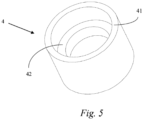
- the resisting member 4 is illustrated in Figure 5 and comprises a support portion 41 for supporting the pressure gauge body 21 and a raised portion 42 protruding radially inward along the support portion 41 to abut against the flexible connecting tube 3.
- the spring 5 is sleeved on the outer side of the flexible connecting tube 3 under the resisting member 4 opposite from the pressure gauge 2.
- the flexible connecting tube 3 extends between an upper end portion and a lower end portion.
- the upper end portion is fixed between the raised portion 42 and the pressure probe 22, and the lower end portion is fixed in communication with the air vent 112 through a tube joint 6.
- the tube joint 6 extends from the accommodating space 111 into the air vent 112.
- the upper end portion of the flexible connecting tube 3 is fixed by the abutment (such as by a pressure fit) between the raised portion 42 and the threaded pressure probe 22.
- the lower end portion of the flexible connecting tube 3 forms an interference fit with the tube joint 6, such that it is fixed in the accommodating space 111 of the handle shell 11 and is in communication with the air vent 112 and pressure gauge 2.
- the hand air pump handle assembly 1 may further include a flexible shock absorber 7 to further improve the impact resistance of the hand air pump handle assembly 1.
- the flexible shock absorber 7 may be arranged between the pressure gauge 2 and the handle shell 11 and may further at least partially cover the pressure gauge 2.
- the flexible shock absorber 7 may be arranged around the pressure gauge body 21 such that it is located between the pressure gauge body 21 and the handle shell 11 to prevent the pressure gauge 2 from directly impacting the handle shell 11 under the influence of external force.
- the flexible shock absorber 7 may comprise of a rubber or a sponge-like material.
- Figure 6 illustrates a second embodiment of a hand air pump handle assembly 1.
- the flexible connecting tube 3 in the second embodiment is fixed in place by at least one of a collar or a ribbon 31. More specifically, the upper end portion of the flexible connecting tube 3 is connected to the pressure probe 22 by a collar or a ribbon 31, and the lower end portion is connected to the upper end portion of the tube joint 6 by a collar or a ribbon 31.
- the tube joint 6 includes a lower end portion that is threaded and at least partially extends through the air vent 112 and is fixed to the handle shell 11 by a fixing member, such as a nut 63.
- the tube joint 6 may further comprise a protrusion 61 extending radially outward above the air vent 112 to assist in supporting the handle shell 11.
- the protrusion 61 is located in the accommodating space 111 and extends a diameter of the tube joint 6 such that the diameter is larger than a diameter of the air vent 112 and cannot be removed therethrough.
- a seal washer 62 surrounding the tube joint 6 is further arranged between the protrusion 61 and the air vent 112 to prevent gas from leaking between the handle shell 11 and the protrusion 61, thereby ensuring that the pressure value detected by the pressure gauge 2 is more accurate.
- the flexible shock absorber 7 may further comprise a shock absorber body 71 that at least partially covers the pressure gauge 2 and at least one shock absorber leg 72 extending from the shock absorber body 71 towards the handle shell 11.
- the shock absorber leg 72 may further bias the pressure gauge 2 away from the handle shell 11.
- the hand air pump handle assembly 1 may further include a shock absorber holder 73 fixed in the accommodating space 111 of the handle shell 11 to support the at least one shock absorber leg 72.
- the shock absorber body 71 covers the sides and a bottom of the pressure gauge body 21, and the shock absorber holder 73 is fixed in the accommodating space 111 by means of fixing members, such as bolts.
- the shock absorber holder 73 is thus located to support the at least one shock absorber leg 72 extending downward from the bottom of the shock absorber body 71.
- the at least one shock absorber leg 72 may include a plurality of shock absorber legs 72, for example, a pair of shock absorber legs 72.
Landscapes
- Engineering & Computer Science (AREA)
- Mechanical Engineering (AREA)
- General Engineering & Computer Science (AREA)
- Compressors, Vaccum Pumps And Other Relevant Systems (AREA)
Description
- The present disclosure relates to a hand air pump handle assembly with an internal pressure gauge and a hand air pump including the hand air pump handle assembly.
- This section provides background information related to the present disclosure which is not necessarily prior art.
- Inflatable bodies (e.g., air mattresses, inflatable sofas, pneumatic tires and inflatable toys) need to be inflated with air before use. Depending on the inflatable body, the amount of inflation, as measured in units of pressure, generally needs to be relatively specific. Too much or too little inflation and the inflatable body can malfunction or break. Electric air pumps and hand air pumps are commonly used to inflate a large variety of inflatable bodies. Too help ensure that the inflatable body is inflated to an ideal pressure, pressure gauges (e.g., electronic and non-electronic pressure gauges) are sometimes mounted on air pump handles and provide current air pressure inside of the inflatable body as it is inflated.
- While mounted pressure gauges have improved operability of certain air pumps, such mounted pressure gauges are generally directly and rigidly mounted onto the pump handle, and thus are susceptible to damage during misuse or an accident with the air pump. More particularly, pressure gauges mounted within air pump handles are not protected from potential damage from physical shock that may result from, for example, dropping the air pump. Generally, when a pressure gauge breaks, it is cheaper and/or more efficient to buy a new air pump rather than attempting to fix the old air pump by replacing the broken pressure gauge.
-
US 8,721,296 B1 relates to o a hand pump or air pump for inflating the inflatable tires or objects or the like of the cycles, such as the bicycles, and more particularly to a hand pump or air pump for a bicycle including an air storage tank. -
GB 251 721 A - Accordingly, there is a need to improve the connection and implementation of a pressure gauge within an air pump handle, so that it is less susceptible to damage.
- The following outlines certain features of embodiments of the present invention such that the detailed description of the invention that follows may be better understood. Additional features of embodiments of the present invention will be described hereinafter. It should be appreciated by those skilled in the art that the general concepts and the specific embodiments disclosed herein may be readily utilized as bases for modifying or designing other embodiments for carrying out the same or similar purposes of the present invention. It should also be realized by those skilled in the art that such equivalent embodiments do not depart from the spirit and scope of the invention, as set forth in the appended claims.
- According to an aspect of the disclosure, a hand air pump handle assembly is provided. The hand air pump handle assembly comprises a handle shell defining an accommodating space and having an air vent in fluid communication with both the accommodating space and a provided inflatable body. A pressure gauge is located and elastically supported within the accommodating space. A flexible connecting tube is in the accommodating space of the handle shell and comprises a first end and a second end and a tube joint connecting the flexible connecting tube to the air vent. A flexible shock absorber is provided being arranged between the pressure gauge and the handle shell for dampening impact between the handle shell and the pressure gauge.
- In accordance with another aspect of the disclosure, the hand air pump handle assembly includes an elastic connector connecting the pressure gauge to the handle shell to permit movement of the pressure gauge within the accommodating space. The pressure gauge comprises a pressure gauge body and a pressure probe extending from the pressure gauge body and in fluid communication with the provided inflatable body through the flexible connecting tube.
- According to another aspect of the disclosure, the elastic connector comprises a resisting member at least partially sleeved over an outer side of the flexible connecting tube. The resisting member comprises a support portion for supporting the pressure gauge body and a raised portion protruding radially inward along the support portion to contact the flexible connecting tube. The elastic connector further comprises a spring sleeved over the outer side of the flexible connecting tube and extending between a pair of ends thereof, wherein one end of the spring abuts against the raised portion of the resisting member, and the other end of the spring is fixed in an annular recess located around the air vent.
- In accordance with another aspect of the disclosure, the flexible connecting tube extends between a pair of ends thereof, wherein one end of the flexible connecting tube is fixed between the raised portion of the resisting member and the pressure probe, and the other end of the flexible connecting tube forms an interference fit with the tube joint. The pressure probe includes a threaded portion extending through the raised portion of the resistance member, and the flexible connecting tube fits between the threaded portion and the raised portion.
- According to yet another aspect of the disclosure, the hand air pump handle assembly further includes at least a pair of cable ties, wherein one of the pair of cable ties affixes the first end of the flexible connecting tube to the pressure probe and the other one of the pair of cable ties affixes the second end of the flexible connecting tube to the tube joint.
- According to yet another aspect of the disclosure, the hand air pump handle assembly further includes a fixing member affixing the tube joint to the handle shell. The tube joint further includes a protrusion located in the accommodating space that extends a diameter of the tube joint such that the diameter is larger than a diameter of the air vent and a seal washer located between the protrusion and the handle shell. The tube joint is at least partially threaded, and the fixing member includes a nut engaged thereon.
- In accordance with another aspect of the disclosure, the hand air pump handle assembly further includes flexible shock absorber arranged between the pressure gauge and the handle shell for dampening impact between the handle shell and the pressure gauge. The flexible shock absorber comprises a shock absorber body at least partially covering the pressure gauge. The flexible shock absorber further comprises at least one shock absorber leg extending from the shock absorber body towards the handle shell to provide additional dampening. The hand air pump handle assembly further includes a holder for the flexible shock absorber fixed in the accommodating space for contacting the shock absorber leg and causing the shock absorber leg to move as the pressure gauge is moved. The flexible shock absorber may comprise a rubber member or a sponge-like material.
- According to yet another aspect of the disclosure, the hand air pump handle assembly further includes the provided inflatable body, wherein the provided inflatable body comprises at least one of an inflatable sofa, an air mattress, an inflatable toy, or a pneumatic tire.
- In accordance to another aspect of the disclosure, the hand air pump handle assembly further includes a cover that can be connected to and disconnected from the handle shell. The cover is at least partially transparent so that the pressure gauge can be viewed therethrough.
- According to yet another aspect of the disclosure, the hand air pump handle assembly further includes a pair of grip portions extending from opposite sides of the handle shell. The handle shell and the pair of grip portions may be integrally formed.
- The drawings described herein are only for illustrative purposes of selected embodiments and are not intended to limit the scope of the present disclosure. The inventive concepts associated with the present disclosure will be more readily understood by reference to the following description in combination with the accompanying drawings wherein:
-
Figure 1 is a disassembled top perspective view of a hand air pump handle assembly, according to a first embodiment of the present disclosure; -
Figure 2 is a disassembled rear perspective view of the hand air pump handle assembly inFigure 1 ; -
Figure 3 is a cross-sectional view of the hand air pump handle assembly inFigure 1 taken along a sectional line A-A; -
Figure 4 is a cross-sectional view of the hand air pump handle assembly inFigure 1 taken along a sectional line B-B; -
Figure 5 is a perspective view of a resisting member of the hand air pump handle assembly inFigure 1 ; and -
Figure 6 is a cross-sectional view of the hand air pump handle assembly, according to a second embodiment of the present disclosure. - Exemplary embodiments will now be described more fully with reference to the accompanying drawings. In general, the subject embodiments are directed to a hand air pump handle assembly and an air pump with the handle assembly. However, the exemplary embodiments are only illustrative of the various features of the present invention, as those skilled in the art understand that various changes thereto may be made without departing from the full scope of the invention. Numerous specific details are set forth, such as examples of specific components, devices, and methods, to provide a thorough understanding of the embodiments of the present disclosure. It will be apparent to those skilled in the art that specific details need not be employed, that exemplary embodiments may be altered in many different forms and that neither should be construed to limit the scope of the disclosure. In some exemplary embodiments, well-known processes, well-known device structures, and well-known technologies are not described in detail. It is to be further noted that the accompanying drawings are not only intended to interpret the present invention, but also to help illustrate exemplary embodiments of the present invention, without limiting the full scope of the invention as set forth in the claims.
- In the present description, the directional terms such as "top", "bottom", "upper" and "lower" are all confined according to the directions in which a hand air pump handle assembly is normally used, as shown in the drawings.
-
Figure 1 to Figure 5 schematically illustrate a first embodiment of a hand airpump handle assembly 1 according to the present disclosure. The hand airpump handle assembly 1 mainly comprises ahandle shell 11 mounted with apressure gauge 2, twogrip portions 12, afirst connector 13, and asecond connector 14. - With initial reference to
Figures 1 and2 , thehandle shell 11 defines an internalaccommodating space 111 for housing thepressure gauge 2. Thehandle shell 11 further defines anair vent 112 formed near the bottom of theaccommodating space 111 to connect theaccommodating space 111 to a pump body (not shown) of the hand air pump and a provided inflatable body (not shown and alternatively referred to as inflatable body). The inflatable body may comprise an air mattress, an inflatable sofa, a pneumatic tire, an inflatable toy, or any other item requiring inflation. The hand airpump handle assembly 1 further comprises acover 8 fixed to the top of thehandle shell 11 to close theaccommodating space 111. Thecover 8 may be fixedly connected to thehandle shell 11 by fixing members, such asbolts 81. Thecover 8 may include a transparent region through which a user can directly observe an air pressure value shown on thepressure gauge 2. - The two
grip portions 12 extend oppositely from sides of thehandle shell 11 for the user to grab with each hand while inflating. Thefirst connector 13 extends through a the bottom of thehandle shell 11 to connect the pump body of the hand air pump to theaccommodating space 111 via theair vent 112. Thesecond connector 14 is located between thehandle shell 11 and thefirst connector 13 to connect the inflatable body via an external inflation tube (not shown). More particularly, one end of the inflation tube is connected to thesecond connector 14 and the other end of the inflation tube is connected to the inflatable body. As such, the inflatable body can communicate with the pump body and theaccommodating space 111 via theair vent 112. Thehandle shell 11, the twogrip portions 12, thefirst connector 13 and thesecond connector 14 are preferably integrally formed. - As best illustrated in
Figures 3 andFigure 4 , thepressure gauge 2 is located in theaccommodating space 111 and connected to thehandle shell 11 by anelastic connector 15 that comprises materials and/or components that allow thepressure gauge 2 to move elastically within theaccommodating space 111. Thepressure gauge 2 comprises apressure gauge body 21 and apressure probe 22. Thepressure probe 22 may include a metal probe with an external thread. Thepressure probe 22 extends from thepressure gauge body 21 toward theair vent 112 and communicates with the inflatable body via a flexible connecting tube 3 (e.g., a silicone connecting tube). The flexible connectingtube 3 is at least partially located in theaccommodating space 111 of thehandle shell 11 and extends from thepressure probe 22 to thevent 112 in order to communicate the internal air pressure value of the inflatable body to thepressure gauge 2. - The
elastic connector 15 includes a resistingmember 4 and aspring 5 that enables thepressure gauge 2 to elastically travel a small dampened distance when under the impact of external forces. The resistingmember 4 assists in the connection between thepressure gauge 2 and the flexible connectingtube 3. More particularly, the resistingmember 4 is sleeved on an outer side of at least a portion of the flexible connectingtube 3. The resistingmember 4 is illustrated inFigure 5 and comprises asupport portion 41 for supporting thepressure gauge body 21 and a raisedportion 42 protruding radially inward along thesupport portion 41 to abut against the flexible connectingtube 3. Thespring 5 is sleeved on the outer side of the flexible connectingtube 3 under the resistingmember 4 opposite from thepressure gauge 2. An upper end portion of thespring 5 abuts a lower surface of the raisedportion 42 of the resistingmember 4, and a lower end portion of thespring 5 is fixed in anannular recess 113 surrounding theair vent 112 and formed in thehandle shell 11. Thespring 5 is biased to hold thepressure gauge 2 centrally within theaccommodating space 111 and away from thehandle shell 11. - The flexible connecting
tube 3 extends between an upper end portion and a lower end portion. The upper end portion is fixed between the raisedportion 42 and thepressure probe 22, and the lower end portion is fixed in communication with theair vent 112 through atube joint 6. Thetube joint 6 extends from theaccommodating space 111 into theair vent 112. In the first embodiment, the upper end portion of the flexible connectingtube 3 is fixed by the abutment (such as by a pressure fit) between the raisedportion 42 and the threadedpressure probe 22. With continued reference to the first embodiment, the lower end portion of the flexible connectingtube 3 forms an interference fit with thetube joint 6, such that it is fixed in theaccommodating space 111 of thehandle shell 11 and is in communication with theair vent 112 andpressure gauge 2. - The hand air
pump handle assembly 1 may further include aflexible shock absorber 7 to further improve the impact resistance of the hand airpump handle assembly 1. Theflexible shock absorber 7 may be arranged between thepressure gauge 2 and thehandle shell 11 and may further at least partially cover thepressure gauge 2. In one arrangement, theflexible shock absorber 7 may be arranged around thepressure gauge body 21 such that it is located between thepressure gauge body 21 and thehandle shell 11 to prevent thepressure gauge 2 from directly impacting thehandle shell 11 under the influence of external force. Theflexible shock absorber 7 may comprise of a rubber or a sponge-like material. -
Figure 6 illustrates a second embodiment of a hand airpump handle assembly 1. Unlike the first embodiment, the flexible connectingtube 3 in the second embodiment is fixed in place by at least one of a collar or aribbon 31. More specifically, the upper end portion of the flexible connectingtube 3 is connected to thepressure probe 22 by a collar or aribbon 31, and the lower end portion is connected to the upper end portion of the tube joint 6 by a collar or aribbon 31. Thetube joint 6 includes a lower end portion that is threaded and at least partially extends through theair vent 112 and is fixed to thehandle shell 11 by a fixing member, such as anut 63. The tube joint 6 may further comprise aprotrusion 61 extending radially outward above theair vent 112 to assist in supporting thehandle shell 11. More specifically, theprotrusion 61 is located in theaccommodating space 111 and extends a diameter of the tube joint 6 such that the diameter is larger than a diameter of theair vent 112 and cannot be removed therethrough. Aseal washer 62 surrounding thetube joint 6 is further arranged between theprotrusion 61 and theair vent 112 to prevent gas from leaking between thehandle shell 11 and theprotrusion 61, thereby ensuring that the pressure value detected by thepressure gauge 2 is more accurate. - With continued reference to
Figure 6 , theflexible shock absorber 7 may further comprise ashock absorber body 71 that at least partially covers thepressure gauge 2 and at least oneshock absorber leg 72 extending from theshock absorber body 71 towards thehandle shell 11. Theshock absorber leg 72 may further bias thepressure gauge 2 away from thehandle shell 11. The hand airpump handle assembly 1 may further include ashock absorber holder 73 fixed in theaccommodating space 111 of thehandle shell 11 to support the at least oneshock absorber leg 72. In one arrangement, theshock absorber body 71 covers the sides and a bottom of thepressure gauge body 21, and theshock absorber holder 73 is fixed in theaccommodating space 111 by means of fixing members, such as bolts. Theshock absorber holder 73 is thus located to support the at least oneshock absorber leg 72 extending downward from the bottom of theshock absorber body 71. The at least oneshock absorber leg 72 may include a plurality ofshock absorber legs 72, for example, a pair ofshock absorber legs 72.
Claims (14)
- A hand air pump handle assembly (1), comprising:an accommodating space (111) and having an air vent (112) in fluid communication with both the accommodating space (111) and a provided inflatable body;a pressure gauge (2) located and elastically supported within the accommodating space (111);a flexible connecting tube (3) in the accommodating space (111) and comprising a first end and a second end;a tube joint (6) connecting the flexible connecting tube (3) to the air vent (112); and characterized in that the hand air pump handle assembly comprises:a handle shell (11) defining the accommodating space (111);a flexible shock absorber (7) arranged between the pressure gauge (2) and the handle shell (11) for dampening impact between the handle shell (11) and the pressure gauge (2).
- The hand air pump handle assembly (1) according to claim 1, further including:an elastic connector (15) connecting the pressure gauge (2) to the handle shell (11) to permit movement of the pressure gauge (2) within the accommodating space (111);wherein the pressure gauge (2) comprises:a pressure gauge body (21); anda pressure probe (22) extending from the pressure gauge body (21) and in fluid communication with the provided inflatable body through the flexible connecting tube (3).
- The hand air pump handle assembly (1) according to claim 2, wherein the elastic connector (15) comprises:a resisting member (4) at least partially sleeved over an outer side of the flexible connecting tube (3), the resisting member (4) comprising a support portion (41) for supporting the pressure gauge body (21) and a raised portion (42) protruding radially inward along the support portion (42) to contact the flexible connecting tube (3); anda spring (5) sleeved over the outer side of the flexible connecting tube (3) and extending between a pair of ends thereof, wherein one end of the spring (5) abuts against the raised portion (42) of the resisting member (4), and the other end of the spring (5) is fixed in an annular recess (113) located around the air vent (112).
- The hand air pump handle assembly (1) according to claim 3, wherein the flexible connecting tube (3) extends between the first end and the second end, wherein the first end of the flexible connecting tube (3) is fixed between the raised portion (42) of the resisting member (4) and the pressure probe (22), and the second end of the flexible connecting tube (3) forms an interference fit with the tube j oint (6).
- The hand air pump handle assembly (1) according to claim 4, wherein the pressure probe (22) includes a threaded portion extending through the raised portion (42) of the resistance member (4) and wherein the flexible connecting tube (3) fits between the threaded portion and the raised portion (42).
- The hand air pump handle assembly (1) according to claim 1, further including at least a pair of cable ties, wherein one of the pair of cable ties affixes the first end of the flexible connecting tube (3) to the pressure probe (22) and the other one of the pair of cable ties affixes the second end of the flexible connecting tube (3) to the tube joint (6).
- The hand air pump handle assembly (1) according to claim 6, further including a fixing member (81) affixing the tube joint (6) to the handle shell (11).
- The hand air pump handle assembly (1) according to claim 7, wherein the tube joint (6) further includes:a protrusion (61) located in the accommodating space (111) that extends a diameter of the tube joint (6) such that the diameter is larger than a diameter of the air vent (112); anda seal washer (62) located between the protrusion (61) and the handle shell (11).
- The hand air pump handle assembly (1) according to claim 8, wherein the tube joint (6) is at least partially threaded and the fixing member (81) includes a nut (63) engaged thereon.
- The hand air pump handle assembly (1) according to claim 1, wherein the flexible shock absorber (7) comprises a shock absorber body (71) at least partially covering the pressure gauge (2).
- The hand air pump handle assembly (1) according to claim 10, wherein the flexible shock absorber (7) further comprises at least one shock absorber leg (72) extending from the shock absorber body (71) towards the handle shell (11) to provide additional dampening.
- The hand air pump handle assembly (1) according to claim 11, further comprising a holder (73) for the flexible shock absorber (7) fixed in the accommodating space (111) for contacting the shock absorber leg (72) and causing the shock absorber leg (72) to move as the pressure gauge (2) is moved.
- The hand air pump handle assembly (1) according to claim 1, wherein the flexible shock absorber (7) comprises a rubber member.
- The hand air pump handle assembly (1) according to claim 1, further comprising a cover (8) that can be connected to and disconnected from the handle shell (11), wherein the cover (8) is at least partially transparent so that the pressure gauge (2) can be viewed therethrough.
Applications Claiming Priority (1)
| Application Number | Priority Date | Filing Date | Title |
|---|---|---|---|
| CN201920767603.2U CN209875418U (en) | 2019-05-27 | 2019-05-27 | Manual air pump handle assembly and manual air pump |
Publications (2)
| Publication Number | Publication Date |
|---|---|
| EP3744979A1 EP3744979A1 (en) | 2020-12-02 |
| EP3744979B1 true EP3744979B1 (en) | 2023-07-05 |
Family
ID=68947932
Family Applications (1)
| Application Number | Title | Priority Date | Filing Date |
|---|---|---|---|
| EP20174750.8A Active EP3744979B1 (en) | 2019-05-27 | 2020-05-14 | Hand air pump handle assembly and hand air pump |
Country Status (3)
| Country | Link |
|---|---|
| US (1) | US11454228B2 (en) |
| EP (1) | EP3744979B1 (en) |
| CN (1) | CN209875418U (en) |
Families Citing this family (1)
| Publication number | Priority date | Publication date | Assignee | Title |
|---|---|---|---|---|
| CN111441932B (en) * | 2020-04-24 | 2025-08-26 | 宁波美高厨具有限公司 | Air pump assembly and cleaning machine |
Family Cites Families (7)
| Publication number | Priority date | Publication date | Assignee | Title |
|---|---|---|---|---|
| GB251721A (en) * | 1925-02-25 | 1926-05-13 | Millicent Smith | Improvements in inflators |
| US3888127A (en) * | 1972-11-10 | 1975-06-10 | Farallon Ind | Portable underwater indicating instrument for divers |
| US5335543A (en) * | 1993-03-16 | 1994-08-09 | U.S. Divers Co., Inc. | Diver's pivotal gauge boot |
| US6485264B1 (en) * | 2000-06-16 | 2002-11-26 | Scott Wu | Anti-leakage device for a manual air pump with a pressure gauge |
| US8721296B1 (en) * | 2013-01-28 | 2014-05-13 | Beto Engineering & Marketing Co., Ltd. | Hand pump with air storage tank |
| TWI540254B (en) * | 2015-02-10 | 2016-07-01 | Shu-Mu Wu | Rotating the pressure gauge |
| TW201802355A (en) * | 2016-07-06 | 2018-01-16 | 極點股份有限公司 | Air inflating device capable of outputting a larger amount of airflow to quickly lift the cover to tightly fit the rim so as to inflate the bike tire without the need of an inner tube |
-
2019
- 2019-05-27 CN CN201920767603.2U patent/CN209875418U/en active Active
-
2020
- 2020-05-14 EP EP20174750.8A patent/EP3744979B1/en active Active
- 2020-05-26 US US16/883,599 patent/US11454228B2/en active Active
Also Published As
| Publication number | Publication date |
|---|---|
| EP3744979A1 (en) | 2020-12-02 |
| US11454228B2 (en) | 2022-09-27 |
| CN209875418U (en) | 2019-12-31 |
| US20200378376A1 (en) | 2020-12-03 |
Similar Documents
| Publication | Publication Date | Title |
|---|---|---|
| US6543277B2 (en) | Non-attached monitoring assembly for pneumatic tire | |
| US11454228B2 (en) | Hand air pump handle assembly and hand air pump | |
| CN110253602A (en) | A kind of inner bearing type fixture | |
| WO2016109030A1 (en) | Tire electronics securing structures | |
| GB2528743A (en) | Bicycle including frame with inflatable segments | |
| US5816284A (en) | Tire valve extension attachment | |
| JP2006507185A (en) | Non-stick monitoring assembly for pneumatic tires | |
| US4653550A (en) | Portable refillable inflator | |
| US2391120A (en) | Spring means | |
| US8540595B1 (en) | Ball inflation valve | |
| US9488540B2 (en) | Barometer with multi-functions of measurement and depressurization | |
| CN214633702U (en) | Station dynamic and static balance function training and evaluating system | |
| KR20170053833A (en) | Airbag Helmet | |
| JP2003182321A (en) | Transmitter of tyre state monitoring device | |
| US20150021873A1 (en) | Wheel system for a vehicle | |
| US20090114294A1 (en) | Portable gas shock or air bag inflator or deflator | |
| US20030144096A1 (en) | Inflatable device | |
| CA1333252C (en) | Pressure indicating valve stem | |
| CN211314475U (en) | Pedal inflator | |
| CN205632431U (en) | Novel tyre aeration device | |
| US3117195A (en) | Pmneumatic tire and electric switch for pressure indicator | |
| CN222254862U (en) | Novel empty spring leather bag protection cover | |
| CN107035656A (en) | A kind of moveable inflated rubber product device | |
| CN219639012U (en) | Rotatable inflation joint and inflation pump | |
| CN212320986U (en) | Vehicle-mounted device convenient for detecting tire pressure |
Legal Events
| Date | Code | Title | Description |
|---|---|---|---|
| PUAI | Public reference made under article 153(3) epc to a published international application that has entered the european phase |
Free format text: ORIGINAL CODE: 0009012 |
|
| STAA | Information on the status of an ep patent application or granted ep patent |
Free format text: STATUS: THE APPLICATION HAS BEEN PUBLISHED |
|
| AK | Designated contracting states |
Kind code of ref document: A1 Designated state(s): AL AT BE BG CH CY CZ DE DK EE ES FI FR GB GR HR HU IE IS IT LI LT LU LV MC MK MT NL NO PL PT RO RS SE SI SK SM TR |
|
| AX | Request for extension of the european patent |
Extension state: BA ME |
|
| STAA | Information on the status of an ep patent application or granted ep patent |
Free format text: STATUS: REQUEST FOR EXAMINATION WAS MADE |
|
| 17P | Request for examination filed |
Effective date: 20210512 |
|
| RBV | Designated contracting states (corrected) |
Designated state(s): AL AT BE BG CH CY CZ DE DK EE ES FI FR GB GR HR HU IE IS IT LI LT LU LV MC MK MT NL NO PL PT RO RS SE SI SK SM TR |
|
| RIC1 | Information provided on ipc code assigned before grant |
Ipc: F04B 33/00 20060101AFI20230210BHEP |
|
| GRAP | Despatch of communication of intention to grant a patent |
Free format text: ORIGINAL CODE: EPIDOSNIGR1 |
|
| STAA | Information on the status of an ep patent application or granted ep patent |
Free format text: STATUS: GRANT OF PATENT IS INTENDED |
|
| INTG | Intention to grant announced |
Effective date: 20230413 |
|
| GRAS | Grant fee paid |
Free format text: ORIGINAL CODE: EPIDOSNIGR3 |
|
| GRAA | (expected) grant |
Free format text: ORIGINAL CODE: 0009210 |
|
| STAA | Information on the status of an ep patent application or granted ep patent |
Free format text: STATUS: THE PATENT HAS BEEN GRANTED |
|
| AK | Designated contracting states |
Kind code of ref document: B1 Designated state(s): AL AT BE BG CH CY CZ DE DK EE ES FI FR GB GR HR HU IE IS IT LI LT LU LV MC MK MT NL NO PL PT RO RS SE SI SK SM TR |
|
| REG | Reference to a national code |
Ref country code: CH Ref legal event code: EP |
|
| REG | Reference to a national code |
Ref country code: AT Ref legal event code: REF Ref document number: 1585071 Country of ref document: AT Kind code of ref document: T Effective date: 20230715 |
|
| REG | Reference to a national code |
Ref country code: DE Ref legal event code: R096 Ref document number: 602020013189 Country of ref document: DE |
|
| REG | Reference to a national code |
Ref country code: IE Ref legal event code: FG4D |
|
| REG | Reference to a national code |
Ref country code: LT Ref legal event code: MG9D |
|
| REG | Reference to a national code |
Ref country code: NL Ref legal event code: MP Effective date: 20230705 |
|
| REG | Reference to a national code |
Ref country code: AT Ref legal event code: MK05 Ref document number: 1585071 Country of ref document: AT Kind code of ref document: T Effective date: 20230705 |
|
| PG25 | Lapsed in a contracting state [announced via postgrant information from national office to epo] |
Ref country code: NL Free format text: LAPSE BECAUSE OF FAILURE TO SUBMIT A TRANSLATION OF THE DESCRIPTION OR TO PAY THE FEE WITHIN THE PRESCRIBED TIME-LIMIT Effective date: 20230705 |
|
| PG25 | Lapsed in a contracting state [announced via postgrant information from national office to epo] |
Ref country code: GR Free format text: LAPSE BECAUSE OF FAILURE TO SUBMIT A TRANSLATION OF THE DESCRIPTION OR TO PAY THE FEE WITHIN THE PRESCRIBED TIME-LIMIT Effective date: 20231006 |
|
| PG25 | Lapsed in a contracting state [announced via postgrant information from national office to epo] |
Ref country code: ES Free format text: LAPSE BECAUSE OF FAILURE TO SUBMIT A TRANSLATION OF THE DESCRIPTION OR TO PAY THE FEE WITHIN THE PRESCRIBED TIME-LIMIT Effective date: 20230705 |
|
| PG25 | Lapsed in a contracting state [announced via postgrant information from national office to epo] |
Ref country code: IS Free format text: LAPSE BECAUSE OF FAILURE TO SUBMIT A TRANSLATION OF THE DESCRIPTION OR TO PAY THE FEE WITHIN THE PRESCRIBED TIME-LIMIT Effective date: 20231105 |
|
| PG25 | Lapsed in a contracting state [announced via postgrant information from national office to epo] |
Ref country code: SE Free format text: LAPSE BECAUSE OF FAILURE TO SUBMIT A TRANSLATION OF THE DESCRIPTION OR TO PAY THE FEE WITHIN THE PRESCRIBED TIME-LIMIT Effective date: 20230705 Ref country code: RS Free format text: LAPSE BECAUSE OF FAILURE TO SUBMIT A TRANSLATION OF THE DESCRIPTION OR TO PAY THE FEE WITHIN THE PRESCRIBED TIME-LIMIT Effective date: 20230705 Ref country code: PT Free format text: LAPSE BECAUSE OF FAILURE TO SUBMIT A TRANSLATION OF THE DESCRIPTION OR TO PAY THE FEE WITHIN THE PRESCRIBED TIME-LIMIT Effective date: 20231106 Ref country code: NO Free format text: LAPSE BECAUSE OF FAILURE TO SUBMIT A TRANSLATION OF THE DESCRIPTION OR TO PAY THE FEE WITHIN THE PRESCRIBED TIME-LIMIT Effective date: 20231005 Ref country code: LV Free format text: LAPSE BECAUSE OF FAILURE TO SUBMIT A TRANSLATION OF THE DESCRIPTION OR TO PAY THE FEE WITHIN THE PRESCRIBED TIME-LIMIT Effective date: 20230705 Ref country code: LT Free format text: LAPSE BECAUSE OF FAILURE TO SUBMIT A TRANSLATION OF THE DESCRIPTION OR TO PAY THE FEE WITHIN THE PRESCRIBED TIME-LIMIT Effective date: 20230705 Ref country code: IS Free format text: LAPSE BECAUSE OF FAILURE TO SUBMIT A TRANSLATION OF THE DESCRIPTION OR TO PAY THE FEE WITHIN THE PRESCRIBED TIME-LIMIT Effective date: 20231105 Ref country code: HR Free format text: LAPSE BECAUSE OF FAILURE TO SUBMIT A TRANSLATION OF THE DESCRIPTION OR TO PAY THE FEE WITHIN THE PRESCRIBED TIME-LIMIT Effective date: 20230705 Ref country code: GR Free format text: LAPSE BECAUSE OF FAILURE TO SUBMIT A TRANSLATION OF THE DESCRIPTION OR TO PAY THE FEE WITHIN THE PRESCRIBED TIME-LIMIT Effective date: 20231006 Ref country code: FI Free format text: LAPSE BECAUSE OF FAILURE TO SUBMIT A TRANSLATION OF THE DESCRIPTION OR TO PAY THE FEE WITHIN THE PRESCRIBED TIME-LIMIT Effective date: 20230705 Ref country code: ES Free format text: LAPSE BECAUSE OF FAILURE TO SUBMIT A TRANSLATION OF THE DESCRIPTION OR TO PAY THE FEE WITHIN THE PRESCRIBED TIME-LIMIT Effective date: 20230705 Ref country code: AT Free format text: LAPSE BECAUSE OF FAILURE TO SUBMIT A TRANSLATION OF THE DESCRIPTION OR TO PAY THE FEE WITHIN THE PRESCRIBED TIME-LIMIT Effective date: 20230705 |
|
| PG25 | Lapsed in a contracting state [announced via postgrant information from national office to epo] |
Ref country code: PL Free format text: LAPSE BECAUSE OF FAILURE TO SUBMIT A TRANSLATION OF THE DESCRIPTION OR TO PAY THE FEE WITHIN THE PRESCRIBED TIME-LIMIT Effective date: 20230705 |
|
| REG | Reference to a national code |
Ref country code: DE Ref legal event code: R097 Ref document number: 602020013189 Country of ref document: DE |
|
| PG25 | Lapsed in a contracting state [announced via postgrant information from national office to epo] |
Ref country code: SM Free format text: LAPSE BECAUSE OF FAILURE TO SUBMIT A TRANSLATION OF THE DESCRIPTION OR TO PAY THE FEE WITHIN THE PRESCRIBED TIME-LIMIT Effective date: 20230705 Ref country code: RO Free format text: LAPSE BECAUSE OF FAILURE TO SUBMIT A TRANSLATION OF THE DESCRIPTION OR TO PAY THE FEE WITHIN THE PRESCRIBED TIME-LIMIT Effective date: 20230705 Ref country code: EE Free format text: LAPSE BECAUSE OF FAILURE TO SUBMIT A TRANSLATION OF THE DESCRIPTION OR TO PAY THE FEE WITHIN THE PRESCRIBED TIME-LIMIT Effective date: 20230705 Ref country code: DK Free format text: LAPSE BECAUSE OF FAILURE TO SUBMIT A TRANSLATION OF THE DESCRIPTION OR TO PAY THE FEE WITHIN THE PRESCRIBED TIME-LIMIT Effective date: 20230705 Ref country code: CZ Free format text: LAPSE BECAUSE OF FAILURE TO SUBMIT A TRANSLATION OF THE DESCRIPTION OR TO PAY THE FEE WITHIN THE PRESCRIBED TIME-LIMIT Effective date: 20230705 Ref country code: SK Free format text: LAPSE BECAUSE OF FAILURE TO SUBMIT A TRANSLATION OF THE DESCRIPTION OR TO PAY THE FEE WITHIN THE PRESCRIBED TIME-LIMIT Effective date: 20230705 |
|
| PLBE | No opposition filed within time limit |
Free format text: ORIGINAL CODE: 0009261 |
|
| STAA | Information on the status of an ep patent application or granted ep patent |
Free format text: STATUS: NO OPPOSITION FILED WITHIN TIME LIMIT |
|
| PG25 | Lapsed in a contracting state [announced via postgrant information from national office to epo] |
Ref country code: IT Free format text: LAPSE BECAUSE OF FAILURE TO SUBMIT A TRANSLATION OF THE DESCRIPTION OR TO PAY THE FEE WITHIN THE PRESCRIBED TIME-LIMIT Effective date: 20230705 |
|
| 26N | No opposition filed |
Effective date: 20240408 |
|
| PG25 | Lapsed in a contracting state [announced via postgrant information from national office to epo] |
Ref country code: SI Free format text: LAPSE BECAUSE OF FAILURE TO SUBMIT A TRANSLATION OF THE DESCRIPTION OR TO PAY THE FEE WITHIN THE PRESCRIBED TIME-LIMIT Effective date: 20230705 |
|
| PG25 | Lapsed in a contracting state [announced via postgrant information from national office to epo] |
Ref country code: BG Free format text: LAPSE BECAUSE OF FAILURE TO SUBMIT A TRANSLATION OF THE DESCRIPTION OR TO PAY THE FEE WITHIN THE PRESCRIBED TIME-LIMIT Effective date: 20230705 |
|
| PG25 | Lapsed in a contracting state [announced via postgrant information from national office to epo] |
Ref country code: BG Free format text: LAPSE BECAUSE OF FAILURE TO SUBMIT A TRANSLATION OF THE DESCRIPTION OR TO PAY THE FEE WITHIN THE PRESCRIBED TIME-LIMIT Effective date: 20230705 |
|
| REG | Reference to a national code |
Ref country code: CH Ref legal event code: PL |
|
| PG25 | Lapsed in a contracting state [announced via postgrant information from national office to epo] |
Ref country code: MC Free format text: LAPSE BECAUSE OF FAILURE TO SUBMIT A TRANSLATION OF THE DESCRIPTION OR TO PAY THE FEE WITHIN THE PRESCRIBED TIME-LIMIT Effective date: 20230705 |
|
| PG25 | Lapsed in a contracting state [announced via postgrant information from national office to epo] |
Ref country code: LU Free format text: LAPSE BECAUSE OF NON-PAYMENT OF DUE FEES Effective date: 20240514 |
|
| PG25 | Lapsed in a contracting state [announced via postgrant information from national office to epo] |
Ref country code: MC Free format text: LAPSE BECAUSE OF FAILURE TO SUBMIT A TRANSLATION OF THE DESCRIPTION OR TO PAY THE FEE WITHIN THE PRESCRIBED TIME-LIMIT Effective date: 20230705 Ref country code: LU Free format text: LAPSE BECAUSE OF NON-PAYMENT OF DUE FEES Effective date: 20240514 Ref country code: CH Free format text: LAPSE BECAUSE OF NON-PAYMENT OF DUE FEES Effective date: 20240531 |
|
| REG | Reference to a national code |
Ref country code: BE Ref legal event code: MM Effective date: 20240531 |
|
| PG25 | Lapsed in a contracting state [announced via postgrant information from national office to epo] |
Ref country code: IE Free format text: LAPSE BECAUSE OF NON-PAYMENT OF DUE FEES Effective date: 20240514 |
|
| PG25 | Lapsed in a contracting state [announced via postgrant information from national office to epo] |
Ref country code: BE Free format text: LAPSE BECAUSE OF NON-PAYMENT OF DUE FEES Effective date: 20240531 |
|
| PGFP | Annual fee paid to national office [announced via postgrant information from national office to epo] |
Ref country code: DE Payment date: 20250513 Year of fee payment: 6 |
|
| PGFP | Annual fee paid to national office [announced via postgrant information from national office to epo] |
Ref country code: GB Payment date: 20250521 Year of fee payment: 6 |
|
| PGFP | Annual fee paid to national office [announced via postgrant information from national office to epo] |
Ref country code: FR Payment date: 20250530 Year of fee payment: 6 |
|
| PG25 | Lapsed in a contracting state [announced via postgrant information from national office to epo] |
Ref country code: CY Free format text: LAPSE BECAUSE OF FAILURE TO SUBMIT A TRANSLATION OF THE DESCRIPTION OR TO PAY THE FEE WITHIN THE PRESCRIBED TIME-LIMIT; INVALID AB INITIO Effective date: 20200514 |
|
| PG25 | Lapsed in a contracting state [announced via postgrant information from national office to epo] |
Ref country code: HU Free format text: LAPSE BECAUSE OF FAILURE TO SUBMIT A TRANSLATION OF THE DESCRIPTION OR TO PAY THE FEE WITHIN THE PRESCRIBED TIME-LIMIT; INVALID AB INITIO Effective date: 20200514 |