Technical Field
-
This disclosure relates to the field of hydraulic transmission devices comprising piston hydrostatic devices such as motors, particularly to variable displacement axial piston hydraulic motors, and more particularly to bent axis hydraulic motors.
Background
-
Generally, piston hydraulic devices may be axial piston machines or radial piston. Variable axial piston hydraulic devices may be bent axis type devices. With bent axis type axial piston devices, the pistons are at an angle to the drive shaft and thrust plate. Bent-axis type hydraulic devices may be operated as pumps or motors.
-
A hydraulic transmission device may comprise a bent axis hydraulic motor coupled to a gearing transmission device.
-
Variable displacement piston hydraulic devices comprise a cylinder block carrying the pistons. The cylinder block rotates about a first axis. The devices also comprise a shaft or a rotor that is configured to couple to a transmission or drive shaft that rotates around a second axis of rotation, also called the transmission axis. Through this shaft, mechanical work that is carried out for the compression of fluid (in the case of the pumps) or mechanical work (in the case of the motors) is determined by the pressure of the operating fluid.
-
In bent axis type device, the first and the second axis are incident. The relative inclination of these axes is varied to vary the stroke of the pistons between the dead points and, accordingly, the displacement of the machine. For varying displacement in the bent-axis type device, the inclination of the cylinder block is varied.
-
Bent axis type devices may be configured to have a dry case to reduce energy loss through splashing. In particular, dry case type of construction may comprise the hydraulic motor being integrated into the gearing housing. The hydraulic motor may be comprised in a separate motor casing that is encompassed in the gearing casing. Alternatively, the hydraulic motor may have a motor casing that is joined to the gearing casing.
-
US2015354355 discloses a hydraulic axial piston machine of dry case type of construction whose casing is provided for connection to a gearing casing so as to form a fluid-tight overall case. The case accommodates a drive assembly that can be adjusted by means of an adjustment device and which serves for delivering hydraulic liquid, and having a drive shaft which is operatively connected to the drive assembly and which is mounted in the case by means of bearings so as to be rotatable about its longitudinal axis, wherein neither the drive assembly, the drive shaft nor the bearings thereof run in a sump of the hydraulic liquid.
-
The present disclosure is directed, at least in part, to improving or overcoming one or more aspects of the prior art device. In particular, to improving the overall encumbrance and reliability of a dry case axial piston hydraulic device.
-
The present disclosure is directed, at least in part, to improving or overcoming one or more aspects of the prior art system.
Brief Summary of the Invention
-
The present disclosure describes a hydraulic transmission device comprising a case; a bent axis hydrostatic motor positioned in the case, the bent axis hydrostatic motor comprising a piston drive assembly; a drive shaft having a shaft portion and a flange portion, the drive shaft being rotatably supported in the case at at least one bearing region positioned on the shaft portion and being operatively coupled to the piston drive assembly at the flange portion; and a gearing assembly provided on the drive shaft and positioned in the case characterised in that the gearing assembly is positioned between the at least one bearing region and the piston drive assembly.
Brief Description of the Drawings
-
The foregoing and other features and advantages of the present disclosure will be more fully understood from the following description of various embodiments, when read together with the accompanying drawings, in which:
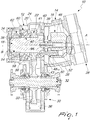
- Fig. 1 is a cross sectional view through a first embodiment of the hydraulic transmission device according to the present disclosure;
- Fig. 2 is a variant of the gearing assembly of Fig. 1;
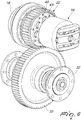
- Fig. 3 is a perspective view of the drive train of Figs. 1;
- Fig. 4 is a cross sectional view through a second embodiment of the hydraulic transmission device according to the present disclosure;
- Fig. 5 is a sectional view through the rotary group of the hydraulic transmission device of Fig. 4 and
- Fig. 6 is a perspective view of the drive train of Figs. 4 and 5.
Detailed Description
-
This disclosure generally relates to a hydraulic transmission device for the transmission of power. Figs. 1, 2, 4 and 5 illustrate the hydraulic transmission device 10. The hydraulic transmission device 10 comprises a case 12, a hydraulic motor 14, a piston drive assembly 16, a drive shaft 18, and at least one bearing region 20 and a gearing assembly 22. With reference to Figs. 1, 2 and 4, the hydraulic transmission device 10 further comprises a driven shaft 32. The driven shaft 32 is provided with a driven gear wheel 33. The hydraulic motor 14 is a bent axis hydraulic motor.
-
With reference to Figs. 1, 2, 4 and 5, the case 12 is configured to accommodate the hydrostatic motor 14 with the piston drive assembly 16, the drive shaft 18, the at least one bearing region 20 and the gearing assembly 22. With reference to Figs. 1, 2 and 4, the driven shaft 32 extends through the case 12. The driven gear wheel 33 is accommodated in the case 12.
-
Case 12 has a first case part 24 and a second case part 26. The first case part 24 is sealingly connected to the second case part 26. The first case part 24 may be connected to the second case part 26 through mechanical connections. Sealing means such as O rings may be used for a fluid tight connection.
-
Fig. 1 illustrates, in the first embodiment, that the first case part 24 accommodates the drive shaft 18, the at least one bearing region 20, the gearing assembly 22 and the driven shaft 32. The second case part 26 accommodates the hydrostatic motor 14 with the piston drive assembly 16. The driven gear wheel 33 is located in the first case part 24.
-
Fig. 4 illustrates, in the second embodiment, that the first case part 24 accommodates a portion of the drive shaft 18, the at least one bearing region 20 and a portion of the driven shaft 32. The second case part 26 accommodates the hydrostatic motor 14 with the piston drive assembly 16, a portion of the drive shaft 18, a portion of the driven shaft 32 and the driven gear wheel 33.
-
With reference to Figs. 1, 4 and 5, the case 12 has an upper portion 28 and a lower portion 30. The hydrostatic motor 14 with the piston drive assembly 16, the drive shaft 18, the bearing region 20 and the gearing assembly 22 are positioned in the upper portion 28 of the case 12. Case 12 has an end cap 34 to enclose the hydrostatic motor 14. The driven shaft 32 is positioned in the lower portion 30.
-
Case 12 may have a dry case configuration. Dry type configuration provides for the piston drive assembly 16 to rotate in an environment free of lubricant fluid. The removal of lubricant fluid may occur through the flow thereof from the upper portion 28 to the lower portion 30. Case 12 may have an oil sump 36 provided at the bottom thereof. The oil sump 36 is positioned in the lower portion 30 below the driven shaft 32.
-
The oil sump 36 is provided to contain lubricant fluid. The lubricant fluid may originate from the hydrostatic motor 14 or from the gearing in the hydraulic transmission drive 10. From the oil sump 36, the lubricant fluid that has flowed in may be removed by means such as pumps (not shown) and conducted into a tank (not shown) and/or resupplied to lubricant ducts (not shown). The hydraulic transmission device 10 could be provided with an appropriate lubrication system (not shown) capable of controlling lubricant oil level in the oil sump 36.
-
The hydraulic motor 14 is positioned in the case 12. The hydraulic motor 14 comprises the piston drive assembly 16. The piston drive assembly 16 comprises a cylinder block 46 having a plurality of cylinder assemblies 48. The cylinder block 46 is rotatable about a rotation axis A. The cylinder block 46 is rotatably supported in the case 12. Cylinder block 46 is rotatably supported in the second case part 26. The cylinder assemblies 48 are radially positioned in the cylinder block 46 relative to the rotation axis A. The cylinder assemblies 48 are mutually angularly spaced about the rotation axis A.
-
Each cylinder assembly 48 comprises a cylinder 50 and a piston 52. Pistons 52 extend and retract in the cylinders 50. Pistons 52 have a piston head 44. Piston head 44 is positioned external to the cylinder 50. Piston 52 travels in the cylinder 50 during a stroke of the piston 52. The cylinder block 46 may comprise conduits for the passage of fluid to the cylinders 50 for the extension or retraction of the pistons 52.
-
Drive shaft 18 has a longitudinal axis B. Drive shaft 18 may be an input shaft of a transmission system. Drive shaft 18 may have a shaft portion 38 and a flange portion 40. Flange portion 40 may be at a terminal end of the drive shaft 18. Flange portion 40 has a first side 39, a second side 41 and an outer surface 43 connecting the first and the second sides 39, 41. Outer surface 43 extends around the flange portion 40. First and second sides 39, 41 are mutually opposite. Second side 41 is configured to have sockets 42 for receiving the piston heads 44. Shaft portion 38 extends from the first surface 39 of the flange portion 40.
-
The drive shaft 18 is operatively coupled to the piston drive assembly 16. Drive shaft 18 is coupled to the piston drive assembly 16 at the flange portion 40. Piston drive assembly 16 is coupled to the flange portion 40 at the second side 41. Drive shaft 18 is coupled to the piston drive assembly 16 without an intervening shaft or rotor. The extension or retraction of the pistons 52 effect a rotation of the drive shaft 18.
-
The drive shaft 18 is rotatably supported in the case 12. Drive shaft 18 is rotatably supported at at least one bearing region 20. The at least one bearing region 20 is positioned on the shaft portion 38. Case 12 has a bearing receiving region 60 that corresponds to the at least one bearing region 20. The drive shaft 18 is rotatably supported so as to be rotatable about the longitudinal axis B. With reference to Fig. 1 and 2 , in the second embodiment, the at least one bearing region 20 is spaced from the flange portion 40. With reference to Fig. 4, in the second embodiment, the at least one bearing region 20 is adjacent the flange portion 40.
-
In an embodiment, the hydraulic transmission device 10 comprises a further bearing region 54. The second bearing region 54 is adjacent to the first bearing region 20. The first bearing region 20 is interposed between the second bearing region 54 and the flange portion 40. Case 12 has a first and a second bearing receiving regions 60, 62 corresponding to the first and second bearing regions 20, 54.
-
The drive shaft 18 is rotatably mounted to the case 12 by a first bearing 56 and a second bearing 58 positioned at the first and second bearing regions 20, 54 respectively. The first and second bearings 56, 58 are tapered rolling bearings. The first and second bearings 56, 58 are positioned in an O configuration.
-
The gearing assembly 22 is provided on the drive shaft 18. Gearing assembly 22 is accommodated in the case 12. Gearing assembly 22 is positioned between the at least one bearing region 20 and the piston drive assembly 16. Gearing assembly 22 meshes with driven gear wheel 33. Gearing assembly 22 is coupled to the driven shaft 32 through the driven gear wheel 33. Rotation of the drive shaft 18 is transmitted to the driven shaft 32 through the gearing assembly 22 meshing with the driven gear wheel 33. The gearing assembly 22 may be coupled to the drive shaft 18 by known mechanical connection systems such as splined profile coupling, tang coupling or interference coupling.
-
The gearing assembly 22 comprises a set of indentations. The indentations are configured to mesh with the driven gear wheel 33. The set of indentations may be formed as a set of teeth. The set of indentations are provided around the drive shaft 18. The set of indentations are formed on the surface of the drive shaft 18. The set of indentations may be arranged concentrically on the drive shaft 18. The set of indentations may be radially positioned on the drive shaft 18 relative to the longitudinal axis B. The set of indentations may be mutually angularly spaced about the longitudinal axis B. In an embodiment, the gearing assembly 22 is a gear wheel. The set of indentations may be configured as teeth of the gear wheel.
-
In the first embodiment, with reference to Figs. 1 to 3, the gearing assembly 22 is positioned on the shaft portion 38. The gearing assembly 22 is positioned adjacent the flange portion 40. The gearing assembly 22 is positioned around the shaft portion 38. The gearing assembly 22 is positioned on the surface of the shaft portion 38. The gearing assembly 22 is formed in the surface of the shaft portion 40.
-
With reference to Figs. 1 and 2, the at least one bearing region 20 is positioned adjacent the gearing assembly 22. In particular, the first bearing region 20 is positioned adjacent the gearing assembly 22. The gearing assembly 22 is interposed between the flange portion 40 and the first bearing region 20. The first bearing region 20 is interposed between the gearing assembly 22 and the second bearing region 54. The first bearing 56 is located adjacent the gearing assembly 22.
-
In a variant of the first embodiment, with reference to Fig. 2, the gearing assembly 22 is formed monolithically with the drive shaft 18. In the second embodiment, with reference to Figs. 4, 5 and 6, the gearing assembly 22 is positioned on the flange portion 40. The gearing assembly 22 is positioned concentrically on the flange portion 40. The gearing assembly 22 is positioned on the outer surface 43 of the flange portion 40. The gearing assembly 22 is positioned around the outer surface 43. The gearing assembly 22 in formed in the outer surface 43.
-
With reference to Figs. 4 and 5, the at least one bearing region 20 is positioned adjacent the flange portion 40. In particular, the first bearing region 20 is positioned adjacent the flange portion 40. The first bearing region 20 is interposed between the flange portion 40 and the second bearing region 54. The first bearing 56 is located adjacent the flange portion 40. First bearing 56 is interposed between the flange portion 40 and the second bearing 58.
-
The skilled person would appreciate that foregoing embodiments may be modified or combined to obtain the hydraulic transmission device 10 of the present disclosure.
Industrial Applicability
-
This disclosure describes a hydraulic transmission device 10 for a transmission system for moving a vehicle. The hydraulic transmission device 10 has a reduced overall encumbrance. The hydraulic transmission device 10 reduces the vehicle installation footprint and reduces the overall length of the motor transmission assembly.
-
Accordingly, this disclosure includes all modifications and equivalents of the subject matter recited in the claims appended hereto as permitted by applicable law. Moreover, any combination of the above-described elements in all possible variations thereof is encompassed by the disclosure unless otherwise indicated herein.
-
Where technical features mentioned in any claim are followed by reference signs, the reference signs have been included for the sole purpose of increasing the intelligibility of the claims and accordingly, neither the reference signs nor their absence have any limiting effect on the technical features as described above or on the scope of any claim elements.
-
One skilled in the art will realise the disclosure may be embodied in other specific forms without departing from the disclosure or essential characteristics thereof. The foregoing embodiments are therefore to be considered in all respects illustrative rather than limiting of the disclosure described herein. Scope of the invention is thus indicated by the appended claims, rather than the foregoing description, and all changes that come within the meaning and range of equivalence of the claims are therefore intended to be embraced therein.