EP3744944B1 - System zur anbindung von untersee-absperrventilen - Google Patents
System zur anbindung von untersee-absperrventilen Download PDFInfo
- Publication number
- EP3744944B1 EP3744944B1 EP20186475.8A EP20186475A EP3744944B1 EP 3744944 B1 EP3744944 B1 EP 3744944B1 EP 20186475 A EP20186475 A EP 20186475A EP 3744944 B1 EP3744944 B1 EP 3744944B1
- Authority
- EP
- European Patent Office
- Prior art keywords
- bop
- subsea
- coupled
- tension
- spool
- Prior art date
- Legal status (The legal status is an assumption and is not a legal conclusion. Google has not performed a legal analysis and makes no representation as to the accuracy of the status listed.)
- Active
Links
Images


Classifications
-
- E—FIXED CONSTRUCTIONS
- E21—EARTH OR ROCK DRILLING; MINING
- E21B—EARTH OR ROCK DRILLING; OBTAINING OIL, GAS, WATER, SOLUBLE OR MELTABLE MATERIALS OR A SLURRY OF MINERALS FROM WELLS
- E21B33/00—Sealing or packing boreholes or wells
- E21B33/02—Surface sealing or packing
- E21B33/03—Well heads; Setting-up thereof
- E21B33/06—Blow-out preventers, i.e. apparatus closing around a drill pipe, e.g. annular blow-out preventers
- E21B33/064—Blow-out preventers, i.e. apparatus closing around a drill pipe, e.g. annular blow-out preventers specially adapted for underwater well heads
-
- E—FIXED CONSTRUCTIONS
- E21—EARTH OR ROCK DRILLING; MINING
- E21B—EARTH OR ROCK DRILLING; OBTAINING OIL, GAS, WATER, SOLUBLE OR MELTABLE MATERIALS OR A SLURRY OF MINERALS FROM WELLS
- E21B41/00—Equipment or details not covered by groups E21B15/00 - E21B40/00
- E21B41/0007—Equipment or details not covered by groups E21B15/00 - E21B40/00 for underwater installations
-
- E—FIXED CONSTRUCTIONS
- E21—EARTH OR ROCK DRILLING; MINING
- E21B—EARTH OR ROCK DRILLING; OBTAINING OIL, GAS, WATER, SOLUBLE OR MELTABLE MATERIALS OR A SLURRY OF MINERALS FROM WELLS
- E21B41/00—Equipment or details not covered by groups E21B15/00 - E21B40/00
- E21B41/04—Manipulators for underwater operations, e.g. temporarily connected to well heads
Definitions
- the disclosure relates generally to systems and methods for tethering subsea structures. More particularly, the disclosure relates to systems and methods for enhancing the strength and fatigue performance of subsea blowout preventers, wellheads, and primary conductors during subsea drilling, completion, production, and workover operations.
- a large diameter hole is drilled to a selected depth in the sea bed.
- a primary conductor extending from the lower end of an outer wellhead housing also referred to as a low pressure housing, is run into the borehole with the outer wellhead housing positioned just above the sea floor/mud line.
- cement is pumped down the primary conductor and allowed to flow back up the annulus between the primary conductor and the borehole sidewall.
- an inner wellhead housing also referred to as a high pressure housing
- a string of casing extending downward from the lower end of the inner wellhead housing (or seated in the inner wellhead housing) is positioned within the primary conductor.
- Cement then is pumped down the casing string, and allowed to flow back up the annulus between the casing string and the primary conductor to secure the casing string in place.
- a blowout preventer BOP
- LMRP lower marine riser package
- the subsea BOP and LMRP are arranged one-atop-the-other.
- a drilling riser extends from a flex joint at the upper end of the LMRP to a drilling vessel or rig at the sea surface.
- the drill string is suspended from the rig through the drilling riser, LMRP, and BOP into the well bore. Drilling generally continues while successively installing concentric casing strings that line the borehole.
- Each casing string is cemented in place by pumping cement down the casing and allowing it to flow back up the annulus between the casing string and the borehole sidewall.
- drilling fluid, or mud is delivered through the drill string, and returned up an annulus between the drill string and casing that lines the well bore.
- the cased well is completed (i.e., prepared for production).
- the horizontal subsea production tree is installed on the wellhead below the BOP and LMRP during completion operations.
- the subsea production tree, BOP, and LMRP are arranged one-atop-the-other.
- Production tubing is run through the casing and suspended by a tubing hanger seated in a mating profile in the inner wellhead housing or production tree.
- the BOP and LMRP are removed from the production tree, and the tree is connected to the subsea production architecture (e.g., production manifold, pipelines, etc.).
- the subsea production architecture e.g., production manifold, pipelines, etc.
- a system as claimed in claim 1 for tethering a subsea blowout preventer (BOP) comprises a plurality of anchors disposed about the subsea BOP and secured to the sea floor.
- the system comprises a plurality of tensioning systems.
- One tensioning system is coupled to an upper end of each anchor.
- the system comprises a plurality of flexible tension members. Each tension member extends from a first end coupled to the subsea BOP to a second end coupled to one of the tensioning systems.
- Each tensioning system is configured to apply a tensile preload to one of the tension members.
- the terms “including” and “comprising” are used in an open-ended fashion, and thus should be interpreted to mean “including, but not limited to."
- the term “couple” or “couples” is intended to mean either an indirect or direct connection. Thus, if a first device couples to a second device, that connection may be through a direct connection, or through an indirect connection via other devices, components, and connections.
- the terms “axial” and “axially” generally mean along or parallel to a central axis (e.g., central axis of a body or a port), while the terms “radial” and “radially” generally mean perpendicular to the central axis.
- an axial distance refers to a distance measured along or parallel to the central axis
- a radial distance means a distance measured perpendicular to the central axis.
- system 10 includes a floating offshore vessel 30 at the sea surface 11, a horizontal production tree 40 releasably connected to a wellhead 50 disposed at an upper end of a primary conductor 51 extending into the wellbore 20, a subsea blowout preventer (BOP) 41 releasably connected to production tree 40, and a lower marine riser package (LMRP) 42 releasably connected to BOP 41.
- Tree 40, BOP 41, and LMRP 42 are vertically arranged or stacked one-above-the-other, and are generally coaxially aligned with wellhead 50.
- Wellhead 50 has a central axis 55 and extends vertically upward from wellbore 20 above the sea floor 12.
- system 10 is shown configured for completion operations, and thus, includes tree 40, however, for drilling operations, tree 40 may not be included.
- vessel 30 is equipped with a derrick 31 that supports a hoist (not shown).
- vessel 30 is a semi-submersible offshore platform, however, in general, the vessel (e.g., vessel 30) can be any type of floating offshore drilling vessel including, without limitation, a moored structure (e.g., a semi-submersible platform), a dynamically positioned vessel (e.g., a drill ship), a tension leg platform, etc.
- a drilling riser 43 (not shown in Figure 2 ) extends subsea from vessel 30 to LMRP 42. During drilling operations, riser 43 takes mud returns to vessel 30.
- BOP 41 includes an outer rectangular prismatic frame 47.
- BOP 41 and LMRP 42 are configured to controllably seal wellbore 20 and contain hydrocarbon fluids therein.
- BOP 41 includes a plurality of axially stacked sets of opposed rams disposed within frame 47.
- BOP 41 can include any number and type of rams including, without limitation, opposed double blind shear rams or blades for severing the tubular string and sealing off wellbore 20 from riser 43, opposed blind rams for sealing off wellbore 20 when no string/tubular extends through BOP 41, opposed pipe rams for engaging the string/tubular and sealing the annulus around string/tubular, or combinations thereof
- LMRP 42 includes an annular blowout preventer comprising an annular elastomeric sealing element that is mechanically squeezed radially inward to seal on a string/tubular extending through LMRP 42 or seal off wellbore when no string/tubular extends through LMRP 42.
- the upper end of LMRP 42 includes a riser flex joint 44 that allows rise
- cyclical loads due to riser vibrations are applied to BOP 41, wellhead 50, and primary conductor 51 extending from wellhead 50 into the sea floor 12.
- riser vibrations e.g., from surface vessel motions, wave actions, current-induced VIV, or combinations thereof
- Such cyclical loads can induce fatigue. This may be of particular concern with subsea horizontal production tree architectures (e.g., system 10) due to the relatively large height and weight of the hardware secured to the wellhead proximal the mud line (i.e., tree, BOP, and LMRP).
- the hardware mounted to wellhead 50 proximal the sea floor 12, production tree 40 and BOP 41 in particular is relatively tall, and thus, presents a relatively large surface area for interacting with environmental loads such as subsea currents. These environmental loads can also contribute to the fatigue of BOP 41, wellhead 50, and primary conductor 51. If the wellhead 50 and primary conductor 51 do not have sufficient fatigue resistance, the integrity of the subsea well may be compromised.
- an uncontrolled lateral movement of vessel 30 e.g., an uncontrolled drive off or drift off of vessel 30
- LMRP 42 laterally with riser 43, thereby inducing bending moments and associated stresses in BOP 41, wellhead 50, and conductor 51.
- Such induced bending moments and stresses can be increased further when the relatively tall and heavy combination of tree 40 and BOP 41 is in a slight angle relative to vertical.
- a tethering system 100 is provided to reinforce BOP 41, wellhead 50, and primary conductor 51 by resisting lateral loads and bending moments applied thereto.
- system 100 offers the potential to enhance the strength and fatigue resistance of BOP 41, wellhead 50, and conductor 51.
- tethering system 100 includes a plurality of anchors 110, a plurality of pile top assemblies 120, and a plurality of flexible tension members 160.
- One pile top assembly 120 is mounted to the upper end of each anchor 110, and one tension member 160 extends from each pile top assembly 120 to frame 47 of BOP 41.
- each pile top assembly 120 includes a tensioning system 140 that can apply tensile loads to the corresponding tension member 160.
- each tensioning system 140 is a winch, and thus, may also be referred to as winch 140.
- winch 140 can pay in and pay out the corresponding tensioning member 160.
- Each tension member 160 includes a first or distal end 160a coupled to frame 47 of BOP 41, and a tensioned span or portion 161 extending from the corresponding winch 140 to end 160a.
- each distal end 160a is coupled to frame 47 of BOP 41 at a height H measured vertically from the sea floor 12 and at a lateral distance D measured radially and horizontally from central axis 55.
- four uniformly circumferentially-spaced anchors 110 and associated tension members 160 are provided.
- height H of each end 160a is the same, lateral distances D to each end 160a is the same.
- lateral distance D is preferably between 5.0 and 15.0 ft, and more preferably about 10.0 ft. However, it should be appreciated that lateral distance D may depend, at least in part, on the available connection points to the frame 47 of BOP 41. As will be described in more detail below, each height H is preferably as high as possible but below LMRP 42, and may depend on the available connection points along frame 47 of BOP 41.
- a tensile preload L is applied to each tensioned span 161.
- the actual tension in each span 161 is the same or substantially the same as the corresponding tensile preload L.
- the actual tension in each span 161 can be greater than or less than the corresponding tensile preload L.
- Winches 140 are positioned proximal to the sea floor 12, and ends 160a are coupled to frame 47 of BOP 41 above winches 140.
- each span 161 is oriented at an acute angle ⁇ measured upward from horizontal. Since portions 161 are in tension and oriented at acute angles ⁇ , the tensile preload L applied to frame 47 of BOP 41 by each span 161 includes an outwardly oriented horizontal or lateral preload L l and a downwardly oriented vertical preload L v .
- the lateral preload L l and the vertical preload L v applied to BOP 41 by each tension member 160 are a function of the corresponding tensile load L and the angle ⁇ .
- the lateral preload L l and the vertical preload L v increase as the tensile load L increases, and decrease as the tensile load L decreases.
- the lateral preload L l decreases and the vertical preload L v increases as angle ⁇ increases, and the lateral preload L l increases and the vertical preload L v decreases as angle ⁇ decreases.
- angle ⁇ of each span 161 is preferably between 10° and 60°, and more preferably between 30° and 45°.
- each height H is preferably as high as possible but below LMRP 42, and may depend on the available connection points along frame 47 of BOP 41.
- ends 160a are coupled to frame 47 proximal the upper end of BOP 41 and just below LMRP 42.
- system 100 By tethering frame 47 of BOP 41 at this location, system 100 restricts and/or prevents BOP 41, tree 40, wellhead 50, and primary conductor 51 from moving and bending laterally, thereby stabilizing such components, while simultaneously allowing LMRP 42 to be disconnected from BOP 41 (e.g., via emergency disconnect package) without any interference from system 100.
- the tensile preload L in each span 161 is preferably as low as possible but sufficient to pull out any slack, curve, and catenary in the corresponding span 161.
- the tensile preload in L in each span 161 is preferably the lowest tension that results in that span 161 extending linearly from the corresponding winch 140 to its end 160a.
- Such tensile loads L in tension members 160 restrict and/or prevent the initial movement and flexing of BOP 41 at the onset of the application of an external loads and/or bending moments, while minimizing the tension in each span 161 before and after the application of the external loads and/or bending moments. The latter consequence minimizes the potential risk of inadvertent damage to BOP 41, tree 40, and LMRP 42 in the event one or more tension members 160 uncontrollably break.
- each tension member 160 can include any elongate flexible member suitable for subsea use and capable of withstanding the anticipated tensile loads (i.e., the tensile preload L as well as the tensile loads induced in spans 161 via the application of external loads to BOP 41) without deforming or elongating.
- suitable devices for tensile members 160 can include, without limitation, chain(s), wire rope, and Dyneema ® rope available from DSM Dyneema LLC of Stanley, North Carolina USA.
- each tension member 160 comprises Dyneema ® rope, which is suitable for subsea use, requires the lowest tensile preload L to pull out any slack, curve, and catenary ( ⁇ 1.0 ton of tension), and is sufficiently strong to withstand the anticipated tensions.
- each tension member 160 is pivotally coupled to one side corner of frame 47 with a fairlead assembly 170.
- each fairlead assembly 170 couples the corresponding tension member 160 to BOP 41 and transfers the tensile loads in the tension member 160 to BOP 41 (i.e., in the form of lateral load L l and vertical loads L v ), while simultaneously allowing the tension member 160 to pivot up and down about its end 160a (i.e., within a vertical plane) and pivot laterally (i.e., left and right) about its end 160a.
- each fairlead assembly 170 is the same and includes a base 171 attached to frame 47, a receiver block 172 pivotally coupled to base 171, and a load pin 173 removably seated in the receiver block 172.
- Base 171 includes a horizontal first or upper plate 171a extending laterally from frame 47 and a second or lower plate 171b extending laterally from frame 47.
- Receiver block 172 is slidably disposed between plates 171a, 171b and pivotally coupled to plates 171a, 171b with a vertical pin 174. As a result, receiver block 172 is free to pivot relative to base 171 and frame 47 about the vertically oriented central axis 175 of pin 174.
- receiver block 172 includes a pair of horizontally spaced arms 176.
- the opposed inner surfaces of each arm 176 include receptacles or pockets 177 extending downward from the top of the corresponding arm 176 to a concave shoulder 178.
- a thimble 179 is disposed in end 160a of tension member 160.
- Load pin 173 is passed through thimble 179 and seated in pockets 176.
- the ends of load pin 173 are slidably seated against concave shoulders 178.
- Each load pin 173 continuously measures the tension in the corresponding tension member 160.
- the measured tensions are communicated to the surface in near real time (or on a period basis).
- the measured tensions can be communicated by any means known in the art including, without limitation, wired communications and wireless communications (e.g., acoustic telemetry).
- fairlead assemblies 170 are attached to frame 47 by welding bases 171 thereto.
- the fairlead assemblies e.g., fairlead assemblies 170
- the fairlead assemblies can be bolted to a suitable location of frame 47.
- system 100 includes one fairlead assembly 170 disposed at or proximal each of the four side corners of frame 47, in other embodiments, the fairlead assemblies (e.g., fairlead assemblies 170) can be coupled to other suitable locations along frame 47.
- the fairlead assemblies 170 are preferably positioned along frame 47 to minimize and/or avoid interference with (a) existing or planned subsea architecture; (b) subsea operations (e.g., drilling, completion, production, workover and intervention operations); (c) wellhead 50, primary conductor 51, tree 40, BOP 41, and LMRP 42; (d) subsea remotely operated vehicle (ROV) operations and access to tree 40, BOP 41, and LMRP 42; and (e) neighboring wells.
- subsea operations e.g., drilling, completion, production, workover and intervention operations
- ROV remotely operated vehicle
- ends 160a of tension members 160 are pivotally coupled to frame 47 of BOP 41 with fairlead assemblies 170.
- the tension members e.g., tension members 160
- the tension members can be coupled to the BOP by other suitable means.
- the fairlead assemblies 170 are eliminated and the distal ends of the tension members (e.g., ends 160a) are directly coupled to the frame 47 (e.g., coupled to pad eyes attached to the BOP with shackle assemblies).
- a load pin or load cell e.g., load pin 173 is preferably provided for each tension member to measure the tension in the corresponding tension member, which is communicated to the surface.
- anchors 110 are circumferentially-spaced about wellhead 50 and secured to the sea floor 12.
- four anchors 110 are uniformly circumferentially-spaced about wellhead 50.
- three or more uniformly circumferentially-spaced anchors 110 are preferably provided.
- each anchor 110 is disposed at a distance R 110 measured radially and horizontally (center-to-center) from wellhead 50. Angles ⁇ are a function of distances R 110 and heights H.
- angles ⁇ can be adjusted as desired.
- each height H is predetermined (e.g., ends 160a are coupled to frame 47 of BOP 41 at the same predetermined location such as the upper end of frame 47 of BOP 41 below LMRP 42)
- angles ⁇ are effectively a function of distances R 110 .
- distances R 110 are generally selected to achieve the preferred angles ⁇ .
- each height H is the same, however, as best shown in Figure 3 , three of the distances R 110 are the same and the fourth distance R 110 is greater than the other three distances R 110 , Consequently, three angles ⁇ are the same, but the fourth angle ⁇ is different.
- the lateral preloads L l applied to BOP 41 are preferably balanced and uniformly distributed.
- the tensile preloads L applied to tension members 160 may need to be adjusted and varied to achieve balanced and uniformly distributed lateral preloads Li.
- each anchor 110 is an elongate rigid member fixably disposed in the seabed.
- each anchor 110 has a vertically oriented central or longitudinal axis 115, an upper end 110a disposed above the sea floor 12, a lower end 110b disposed in the seabed below the sea floor 12, a cylindrical outer surface 111 extending axially between ends 110a, 110b, and an annular lip or flange 112 ( Figure 9 ) extending radially outward from outer surface 111 proximal upper end 110a.
- each anchor 110 is a subsea pile, and thus, anchors 110 may also be referred to as piles 110.
- Each pile 110 is embedded in the seabed and, in general, can be any suitable type of pile including, without limitation, a driven pile or suction pile. Typically, the type of pile employed will depend on a variety of factors including, without limitation, the soil conditions at the installation site. Piles 110 are sized to penetrate the seabed to a depth to sufficiently resist the anticipated tensile loads applied to tension members 160 (i.e., the anticipated tensile preloads L plus any additional tensile loads resulting from the loads and bending moments applied to BOP 41) without moving laterally or vertically relative to the sea floor 12.
- tension members 160 i.e., the anticipated tensile preloads L plus any additional tensile loads resulting from the loads and bending moments applied to BOP 41
- one pile top assembly 120 is releasably mounted to the upper end 110a of one anchor 110.
- each pile top assembly 120 is the same, and thus, one pile top assembly 120 will be described it being understood that the other pile top assemblies 120 are the same.
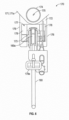
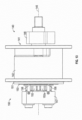
- Pile top assembly 120 includes an adapter 121 removably mounted to the upper end 110a of pile 110, a plurality of uniformly circumferentially-spaced locking rams 130 attached to adapter 121, and winch 140 fixably secured to adapter 121.
- Adapter 121 is a generally cylindrical sleeve having a first or upper end 121a, a second or lower end 121b, a radially inner annular shoulder 122, and a receptacle 123 extending axially from lower end 121b to flange 122.
- Receptacle 123 is sized and configured to receive upper end 110a of anchor 110.
- an annular funnel 124 is disposed at lower end 121b.
- Adapter 121 is generally coaxially aligned with anchor 110, and then lowered onto upper end 110a of anchor 110.
- Upper end 110a is advanced through lower end 121b and receptacle 123 until end 110a axially abuts shoulder 122. With end 110a of anchor 110 sufficiently seated in receptacle 123, it is releasably locked therein with locking rams 130 described in more detail below.
- a guide 125 for tension member 160 is secured to upper end 121a. Tensioning member 160 extends from winch 140 through guide 124 to end 160a. Thus, guide 125 generally directs tension member 160 as it is paid in and paid out from winch 140.
- locking rams 130 are actuated to engage and disengage upper end 110a of pile 110, which is coaxially disposed in receptacle 123, and releasably lock pile top assembly 120 to pile 110.
- Each ram 130 includes a double-acting linear actuator 131 mounted to adapter 121 between ends 121a, 121b and a gripping member or ram block 132 coupled to the actuator 131.
- Each gripping member 132 is mounted to the radially inner end of the corresponding actuator 131 and extends into receptacle 123.
- Actuators 131 are actuated to move gripping members 132 radially inward into engagement with outer surface 111 of pile 110 and radially outward out of engagement with pile 110.
- Locking rams 130 are axially positioned along adapter 121 such that when actuators 131 are operated to move gripping members 132 into engagement with outer surface 111, each gripping member 132 is axially disposed immediately below annular lip 112. Thus, when gripping members 132 are moved into engagement with outer surface 111 of pile 110, friction between gripping members 132 and outer surface 111 and axial engagement of gripping members 132 with lip 112 prevent adapter 121 from being removed from pile 110.
- each actuator 131 is an ROV operated hydraulic piston-cylinder assembly.
- winch 140 is fixably mounted to upper end 121a of adapter 121.
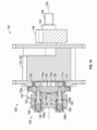
- Winch 140 includes a spool 141 rotatably coupled to adapter 121 and a locking mechanism or brake 150 coupled to spool 141 and adapter 121.
- Spool 141 is selectively rotated relative to adapter 121 to pay in and pay out tension member 160.
- locking mechanism 150 releasably locks spool 141 relative to adapter 121.
- Spool 141 has a horizontal axis of rotation 145 and includes a drum 142 around which tension member 160 is wound, a driveshaft 143 extending from one side of drum 142, and a support shaft 144 extending from the opposite side of drum 142.
- Drum 142 and shafts 143, 144 are coaxially aligned with axis 145.
- Driveshaft 143 extends through a connection block 146 fixably mounted to upper end 121a of adapter 121 and support shaft 144 extends into a connection block 147 fixably mounted to upper end 121a of adapter 121.
- Each shaft 143, 144 is rotatably supported within block 146, 147, respectively, with an annular bearing.
- the distal end of driveshaft 143 comprises a torque tool interface 148 designed to mate with a subsea ROV torque tool.
- locking mechanism 150 includes an annular spool ring 151 disposed about shaft 144 and coupled to drum 142, a hub 152 extending from block 147 and disposed about shaft 144, an annular lock ring 153 slidably mounted to hub 152, and an actuation system 154 that moves lock ring 153 axially along hub 152 into and out of spool ring 151.
- Spool ring 141, hub 152, and lock ring 153 are coaxially aligned with axis 145.
- Spool ring 151 is fixably mounted to drum 142, and hub 152 is integral with connection block 147.
- Spool ring 151 includes a plurality of internal splines 151a
- hub 152 includes a plurality of external splines 152a
- lock ring 153 includes a plurality of external splines 153a and a plurality of internal splines 153b.
- Splines 151a, 152a, 153a, 153b are all oriented parallel to axis 145.
- Internal splines 151a of spool ring 151 and external splines 153a of lock ring 153 are sized and configured to mate, intermesh, and slidingly engage; and external splines 152a of hub 152 and internal splines 153b of lock ring 153 are sized and configured to mate, intermesh, and slidingly engage.
- Lock ring 153 is slidingly mounted to hub 152 with mating splines 152a, 153b intermeshing, and thus, lock ring 153 can move axially along hub 152 but engagement of splines 152a, 153b prevents lock ring 153 from rotating relative to hub 152.
- actuating system 154 moves lock ring 153 along hub 152 into and out of spool ring 151. More specifically, as best shown in Figure 12 , when lock ring 153 is positioned outside of spool ring 151, splines 151a, 153a are axially spaced apart and drum 142 is free to rotate relative to lock ring 153, hub 152, and adapter 121. However, as best shown in Figure 13 , when lock ring 153 is positioned inside spool ring 151, mating splines 151a, 153a intermesh, thereby preventing drum 142 from rotate relative to lock ring 153.
- locking mechanism 150 and lock ring 153 may be described as having an "unlocked” position ( Figure 12 ) with lock ring 153 positioned outside of spool ring 151, thereby allowing drum 142 to rotate freely relative to lock ring 153, hub 152, and adapter 121; and a "locked” position ( Figure 13 ) with lock ring 153 positioned inside of spool ring 151, thereby preventing drum 142 from rotating relative to lock ring 153, hub 152, and adapter 121.
- mating splines 152a, 153b have greater circumferential widths than mating splines 151a, 153a.
- the greater the circumferential width of a spline the greater the torque that can be transferred by that spline.
- splines 152a, 153b having a relatively large circumferential widths can transfer relatively large torques.
- Splines 151a, 153b have relatively smaller circumferential widths, but enable enhanced mating resolution.
- the relatively smaller splines 151a, 153b enable alignment of splines 151a, 153b, as is necessary for insertion of lock ring 153 into spool ring 151, via rotation of spool ring 151 relative to lock ring 153 through a relatively small angle. This enables relatively fine adjustment of the tensile preload L applied to tension member 160.
- actuation system 154 transitions lock ring 153 and locking mechanism 150 between the locked and unlocked positions.
- actuation system 154 includes a plurality of double-acting linear actuators 155 coupled to lock ring 153. Actuators 155 are uniformly circumferentially-spaced about axis 145. In addition, each actuator 155 is the same, and thus, one actuator 155 will be described it being understood the other actuators 155 are the same.
- each actuator 155 is an ROV operated hydraulic piston-cylinder assembly including a cylinder 156 disposed in block 147, a piston 157 slidably disposed in cylinder 156, an extension rod 158 coupling piston 157 to lock ring 153, and a biasing member 159 disposed in cylinder 156.
- Piston 157 divides cylinder 156 into two chambers 156a, 156b. Chamber 156a is vented to the external environment. Biasing member 159 biases piston 157 toward spool ring 151 (to the right in Figure 10 ), thereby biasing lock ring 153 and locking mechanism 150 to the locked position. However, by applying sufficient hydraulic pressure to chamber 156b, the biasing force of biasing member 159 is overcome and piston 156 is moved away from spool ring 151 (to the left in Figure 10 ), thereby transitioning lock ring 153 and locking mechanism 150 to the unlocked position.
- biasing member 159 is a coil spring.
- the tensile preload L is applied to tension member 160 by transitioning lock ring 153 and locking mechanism 150 to the unlocked position via operation of actuation system 154 with a subsea ROV, and then rotating spool 141 about axis 145 with an ROV operated torque tool engaging interface 148 to pay in tension member 160.
- the tension member 160 and/or tension measured with the corresponding load pin 173 can be monitored until the desired tensile preload L is applied (i.e., the slack, curve, and catenary in tension member 160 is removed).
- locking mechanism 150 and lock ring 153 are allowed to transitioned back to the locked position via biasing members 159.
- Winch 140 and more specifically locking mechanism 150, has a sufficiently high holding capacity (e.g., on the order of hundreds of tons) to prevent the inadvertent pay out of tension member 160 when locking mechanism 150 is locked and external loads are applied to BOP 41.
- the arrangement with winches 140 coupled to anchors 110 is generally preferred as it generally requires less interaction with BOP 41 and a lower likelihood of interference with the BOP 41 (including frame 47), other subsea equipment, and subsea operations.
- ROVs remote operated vehicles
- Each ROV preferably includes an arm with a claw for manipulating objects and a subsea camera for viewing the subsea operations. Streaming video and/or images from the cameras are communicated to the surface or other remote location for viewing on a live or periodic basis.
- piles 110 are deployed subsea and installed subsea.
- piles 110 are lowered subsea from a surface vessel such as vessel 30 or a separate construction vessel.
- piles 110 can be lowered subsea by any suitable means such as wireline.
- piles 110 are installed (i.e., secured to the sea floor 12).
- each pile 110 is vertically oriented and positioned immediately above the desired installation location in the sea floor 12 (i.e., at the desired circumferential position about wellhead 50 and at the desired radial distance R 110 ).
- each pile 110 is advanced into the sea floor 12 (driven or via suction depending on the type of pile 110) until upper end 110a is disposed at the desired height above the sea floor 12.
- piles 110 can be installed one at a time, or two or more at the same time.
- pile top assemblies 120 are deployed subsea and coupled to upper ends 110a of piles 110.
- assemblies 120 are lowered subsea from a surface vessel such as vessel 30 or a separate construction vessel.
- assemblies 120 can be lowered subsea by any suitable means such as wireline.
- assemblies 120 are lowered onto to ends 110a of piles 110 and locked thereon as previously described.
- Assemblies 120 are preferably mounted to piles 110 with each guide 125 aligned with the corresponding fairlead assembly 170.
- assemblies 120 can be installed one at a time, or two or more at the same time.
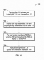
- locking mechanisms 150 are transitioned to the unlocked positions and tension members 160 are paid out from winches 140.
- ends 160a are coupled to frame 47 of BOP 41 via fairlead assemblies 170.
- fairlead assemblies 170 can be deployed and installed at any time prior to block 183.
- tensile preloads L are applied to tension members 160 as previously described. Namely, the tensile preload L is applied to each tension member 160 by unlocking mechanism 150, and then rotating spool 141 with an ROV operated torque tool engaging interface 148 to pay in tension member 160. The tension member 160 and/or tension measured with the corresponding load pin 173 is monitored until the desired tensile preload L is applied (i.e., the slack, curve, and catenary in tensioned span 161 of tension member 160 is removed). Once the desired tensile preload L is achieved, locking mechanism 150 is transitioned to and maintained in the locked position.
- tethering system 100 can be deployed and installed on an existing frame 47 of BOP 41.
- system 100 provides an option for reinforcing existing stacks (e.g., BOP 41) before, during, or after drilling operations, completion operations, production operations, or workover operations.
- pile top assemblies 120 are releasably coupled to piles 110, assemblies 120 and winches 140 mounted thereto can be retrived and reused at different locations.
- tethering system 100 is deployed and installed. Once installed and tensile preloads L are applied, tethering system 100 reinforces and/or stabilizes BOP 41, wellhead 50 and conductor 51 by restricting the lateral/radial movement of BOP 41. As a result, embodiments of tethering system 100 described herein offer the potential to reduce the stresses induced in BOP 41, tree 40, wellhead 50 and primary conductor 51, improve the strength and fatigue resistance of BOP 41, tree 40, wellhead 50 and primary conductor 51, and improve the bending moment response along primary conductor 51 below the sea floor 12.
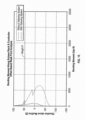
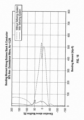
- FIGS 15-17 system 10, and in particular, primary conductor 51, wellhead 50, BOP 41, and LMRP 42 were modeled and simulations were run with and without tethering system 100 to assess the impact of tethering system 100.
- Figures 15-17 graphically illustrate the results of those simulations with and without tethering system 100.
- FIG. 18 another embodiment of a tethering system 200 for reinforcing BOP 41, wellhead 50, and primary conductor 51 of system 10 is shown. Similar to tethering system 100 previously described, in this embodiment, tethering system 200 reinforces BOP 41, wellhead 50, and primary conductor 51 by resisting lateral loads and bending moments applied thereto. As a result, system 200 offers the potential to enhance the strength and fatigue resistance of BOP 41, wellhead 50, and conductor 51.
- system 10 is shown configured for completion operations, and thus, includes tree 40, however, in Figure 19 , system 10 is shown configured for drilling operations, and thus, tree 40 is not included.
- tethering system 200 includes a plurality of anchors 110, a plurality of pile top assemblies 212 mounted to anchors 110, a plurality of tensioning systems 220 releasably coupled to pile top assemblies 212, and a plurality of flexible tension members 160.
- Anchors 110 and tension members 160 are each as previously described.
- tensioning systems 220 are winches, and thus, may also be referred to as winches 220.
- Different devices for applying and maintaining tension on the flexible tension members e.g., tension members 160
- One winch 220 is coupled to each anchor 110, and one tension member 160 is wound to each winch 220 such that each flexible tension member 160 can be paid in and paid out from the corresponding winch 220.
- Distal end 160a of each tension member 160 is coupled to frame 47 of BOP 41, and tensioned span 161 of each tension member 160 extends from the corresponding winch 220 to end 160a.
- each distal end 160a is coupled to frame 47 of BOP 41 at a height H measured vertically from the sea floor 12 and at a lateral distance D measured radially and perpendicularly from central axis 55.
- each height H is the same and each lateral distance D is the same.
- lateral distance D is preferably between 5.0 and 15.0 ft, and more preferably about 10.0 ft.
- lateral distance D may depend, at least in part, on the available connection points to the frame 47 of BOP 41.
- Tensile preload L is provided on each tensioned span 161 of tension members 160 with the corresponding winch 220. With no external loads or moments applied to BOP 41, the actual tension in each span 161 is the same or substantially the same as the corresponding tensile preload L. However, as previously described, when external loads and/or bending moments are applied to BOP 41, the actual tension in each span 161 can be greater than or less than the corresponding tensile preload L.
- Winches 220 are positioned proximal to the sea floor 12, and ends 160a are coupled to frame 47 of BOP 41 above winches 220.
- each span 161 is oriented at an acute angle ⁇ measured upward from horizontal Since portions 161 are in tension and oriented at acute angles ⁇ , the tensile preload L applied by each tension member 160 frame 47 of BOP 41 includes an outwardly oriented horizontal or lateral preload L l and a downwardly oriented vertical preload L v .
- the lateral preload L l and the vertical preload L v applied to BOP 41 by each tension member 160 are a function of the corresponding tensile load L and angle ⁇
- the lateral preload L l and the vertical preload L v increase as the tensile load L increases, and decrease as the tensile load L decreases.
- the lateral preload L l decreases and the vertical preload L v increases as angle ⁇ increases
- angle ⁇ of each span 161 is preferably between 10° and 60°, and more preferably between 30° and 45°.
- each height H is preferably as high as possible but below LMRP 42, and may depend on the available connection points along frame 47 of BOP 41.
- ends 160a are coupled to frame 47 at the upper end of BOP 41, just below LMRP 42.
- system 200 By tethering frame 47 of BOP 41 at this location, system 200 restricts and/or prevents BOP 41, tree 40, wellhead 50, and primary conductor 51 from moving and bending laterally, thereby stabilizing such components, while simultaneously allowing LMRP 42 to be disconnected from BOP 41 (e.g., via emergency disconnect package) without any interference by system 200.
- the tensile preload L in each tension member 160 is preferably as low as possible but sufficient to pull out any slack, curve, and catenary in the corresponding tension member 160.
- the tensile preload L in each tension member 160 is preferably the lowest tension that results in the corresponding span 161 extending linearly from the corresponding winch 220 to its end 160a. It should be appreciated that such tensile loads L in tension members 160 restrict and/or prevent the initial movement and flexing of BOP 41 at the onset of the application of an external loads and/or bending moments, while minimizing the tension in tension members 160 before and after the application of external loads and/or bending moments. The latter consequence minimizes the potential risk of damage to BOP 41, tree 40, and LMRP 42 in the event one or more tension members 160 uncontrollably break.
- each end 160a is pivotally coupled to frame 47 of BOP 41 with an adapter plate 250.
- Each adapter plate 250 has a first or BOP end 250a pivotally coupled to frame 47 of BOP 41 at height H (from the sea floor 12) and lateral distance D (measured radially and perpendicular to axis 55), and a second or tension member end 250b coupled to end 160a.
- each end 250a is pivotally coupled to two pad eyes 47a disposed on the same side of frame 47 at height H and lateral distance D
- each end 250b is pivotally coupled to the corresponding end 160a with a shackle assembly 251.
- This arrangement allows each plate 250 and corresponding tension member 160 to pivot relative to frame 47 of BOP 41 about a horizontal axis 252, and allows each tension member 160 to pivot relative to the corresponding plate 250 about an axis 253 oriented perpendicular to (e.g., through the planar surface of) plate 250.
- each shackle assembly 251 includes a load cell 254 that continuously measures the tension in the corresponding tension member 160.
- the measured tensions are communicated to the surface in near real time (or on a period basis).
- the measured tensions can be communicated by any means known in the art including, without limitation, wired communications and wireless communications (e.g., acoustic telemetry).
- the tensions measured by load cells 254 are communicated acoustically to the surface by a preexisting acoustic communication system housed on BOP 41. Communication of the measured tension in each tension member 160 to the surface enables operators and other personnel at the surface (or other remote location) to monitor the tensions, quantify the external loads on BOP 41, and identify any broken tension member(s) 240.
- ends 160a of tension members 160 are pivotally coupled to frame 47 of BOP 41 with adapter plates 250.
- the tension members e.g., tension members 160
- the tension members can be coupled to the stack by other suitable means.
- plates 250 are eliminated and the distal ends of the tension members (e.g., ends 160a) are directly coupled to the frame 47 (e.g., coupled to pad eyes 127a with shackle assemblies 251).
- a load cell e.g., load cell 254 is preferably provided for each tension member to measure the tension in the corresponding tension member, which is communicated to the surface.
- anchors 110 are uniformly circumferentially-spaced about wellhead 50. However, in general, three or more uniformly circumferentially-spaced anchors 110 are preferably provided.
- the circumferential positions of anchors 110 are selected to avoid unduly interfering with (a) existing or planned subsea architecture; (b) subsea operations (e.g., drilling, completion, production, workover and intervention operations); (c) wellhead 50, primary conductor 51, tree 40, BOP 41, and LMRP 42; (d) subsea remotely operated vehicle (ROV) operations and access to tree 40, BOP 41, and LMRP 42; and (e) neighboring wells.
- ROV remotely operated vehicle
- each anchor 110 is disposed at a distance R 110 measured radially (center-to-center) from wellhead 50.
- Angles ⁇ are a function of distances R 110 and heights H.
- angles ⁇ can be adjusted as desired.
- each height H is predetermined (e.g., ends 160a are coupled to frame 47 of BOP 41 at the same predetermined location such as the upper end of frame 47 of BOP 41 below LMRP 42)
- angles ⁇ are effectively a function of distances R 110 .
- radial distances R 110 are generally selected to achieve the preferred angles ⁇ without unduly interfering with (a) existing or planned subsea architecture; (b) subsea operations (e.g., drilling, completion, production, workover and intervention operations); (c) wellhead 50, primary conductor 51, tree 40, BOP 41, and LMRP 42; (d) subsea remotely operated vehicle (ROV) operations and access to tree 40, BOP 41, and LMRP 42; and (e) neighboring wells.
- subsea operations e.g., drilling, completion, production, workover and intervention operations
- ROV remotely operated vehicle
- each radial distance R 110 is the same.
- each tension preload L is the same
- each height H is the same
- each angle ⁇ is the same
- each distance R 110 is the same.
- one or more preload L can be different and/or varied
- one or more height H can be different and/or varied
- one or more angle ⁇ can be different and/or varied
- one or more radial distance R 110 can be different and/or varied, or combinations thereof
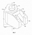
- each pile top assembly 212 is mounted to upper end 110a of each pile 110.
- each pile top assembly 212 includes a cap 213 fixably secured to the upper end 110a of pile 110 and an anchor adapter 216 releasably coupled to cap 213.
- Cap 213 and adapter 216 are coaxially aligned with axis 115.
- Cap 213 has a first or upper end 213a including a receptacle 214a and a second or lower end 213b including a receptacle 214b.
- the upper end 110a of pile 110 is seated in receptacle 214b and fixably secured to cap 213.
- adapter 216 has a first or upper end 216a and a second or lower end 216b.
- adapter 216 includes a generally annular connection body 218 at upper end 216a and an elongate pin or stabbing member 219 extending axially from body 218 to end 216b.
- Pin 219 is received by receptacle 214a and releasably locked therein, thereby releasably connecting adapter 216 to cap 213 and pile 110.
- any locking mechanism known in the art can be employed to releasably lock pin 219 in the mating receptacle 214a.
- Connection body 218 has a planar upward facing surface 218a and a plurality of uniformly circumferentially-spaced receptacles 218b disposed proximal the perimeter of surface 218a and extending downward from surface 218a.
- Each receptacle 218b is sized and configured to receive a mating pin or stabbing member 225 provided on each winch 220.
- the position of one or more winches 220 coupled thereto can be varied as desired. With pin 225 of the winch 220 sufficiently seated in the desired receptacle 218b, it is releasably locked therein.
- any locking mechanism known in the art can be employed to releasably lock pin 225 of the winch 220 in a given receptacle 218b.
- the locking mechanism prevents the winch 220 from moving axially relative to body 218, but allows the winch 220 to rotate about the central axis of the winch pin relative to body 218.
- each winch 220 is releasably coupled to the corresponding adapter 216 via receptacle 218b, and each adapter 216 is releasably coupled to the corresponding cap 213 and pile 110 via receptacle 214a
- winches 220 and adapters 216 can be retrieved to the surface, moved between different subsea piles 110, and reused.
- winches 220 are configured to stab into adapters 216
- adapters 216 are configured to stab into caps 213 in this embodiment
- the adapters e.g., adapters 216) can stab into the winches (e.g., winches 220) and/or the cap (e.g., cap 213) can stab into the adapter.
- the arrangement with tensioning systems 220 coupled to anchors 210 is generally preferred as it generally requires less interaction with BOP 41 and a lower likelihood of interference with the BOP 41 (including frame 47), other subsea equipment, and subsea operations.
- each tensioning system 220 is a winch.
- each tensioning system 220 includes a base 221, a spool 222 rotatably coupled to base 221, a torque tool interface 223 coupled to spool 222, and a locking mechanism or brake 224 coupled to spool 222 and base 221.
- a pin or stabbing member 225 of winch 220 removably received in receptacle 218b of adapter 216 is not shown in Figures 22 and 23 , but generally extends downward from base 221.
- Locking mechanism 224 releasably locks spool 222 relative to base 221.
- locking mechanism 224 has a "locked” position preventing spool 222 from rotating relative to base 221 and pile 110, and an "unlocked” position allowing spool 222 to rotate relative to base 221 and pile 110.
- locking mechanism 224 can be any suitable locking mechanism known in the art or any locking mechanism described here (e.g., locking mechanism 150 previously described).
- the tensile preload L is applied to tension member 160 by unlocking mechanism 224, and then rotating spool 222 with an ROV operated torque tool engaging interface 223 to pay in tension member 160.
- the tension member 160 and/or tension measured with the corresponding load cell 254 can be monitored until the desired tensile preload L is applied (i.e., the slack, curve, and catenary in tension member 160 is removed). Once the desired tensile preload L is achieved, locking mechanism 224 is transitioned to and maintained in the locked position.
- Winch 220 and more specifically locking mechanism 224, has a sufficiently high holding capacity (e.g., on the order of hundreds of tons) to prevent the inadvertent pay out of tension member 160 when locking mechanism 224 is locked and external loads are applied to BOP 41.
- a sufficiently high holding capacity e.g., on the order of hundreds of tons
- ROVs remote operated vehicles
- Each ROV preferably includes an arm with a claw for manipulating objects and a subsea camera for viewing the subsea operations. Streaming video and/or images from the cameras are communicated to the surface or other remote location for viewing on a live or periodic basis.
- each ROV is preferably configured to operate a subsea torque tool to apply the tensile preload L to tension members 160.
- piles 110 are deployed subsea with caps 213 mounted thereto.
- piles 110 are lowered subsea from a surface vessel such as vessel 30 or a separate construction vessel.
- piles 110 can be lowered subsea by any suitable means such as wireline.
- piles 110 are installed (i.e., secured to the sea floor 12).
- each pile 110 is vertically oriented and positioned immediately above the desired installation location in the sea floor 12 (i.e., at the desired circumferential position about wellhead 50 and at the desired radial distance R 110 ).
- each pile 110 is advanced into the sea floor 12 (driven or via suction depending on the type of pile 110) until cap 213 is disposed at the desired height above the sea floor 12.
- piles 110 can be installed one at a time, or two or more at the same time.
- adapters 216 are deployed subsea and coupled to caps 213.
- adapters 216 are lowered subsea from a surface vessel such as vessel 30 or a separate construction vessel.
- adapters 216 can be lowered subsea by any suitable means such as wireline.
- adapters 216 are coupled to caps 213 and piles 110 by aligning each pin 219 with the corresponding receptacle 214a, lowering adapters 216 to seat pins 219 in receptacles 214, and then releasably locking pins 219 within receptacles 214, thereby forming anchors 210.
- adapters 216 can be installed one at a time, or two or more at the same time.
- winches 220 are deployed subsea and coupled to adapters 216 in block 283.
- winches 220 are lowered subsea from a surface vessel such as vessel 30 or a separate construction vessel
- winches 220 can be lowered subsea by any suitable means such as wireline.
- Winches 220 are preferably deployed subsea with tension members 160 coupled thereto.
- winches 220 are coupled to adapters 216 by aligning the pin of each winch 220 with the corresponding receptacle 218b, lowering winches 220 to seat the winch pins in receptacles 218b, and then releasably locking the winch pins within receptacles 218b.
- winches 220 can be installed one at a time, or two or more at the same time.
- tension members 160 are paid out from winches 220 with locking mechanisms 224 in the unlocked positions, and ends 160a are coupled to frame 47 of BOP 41.
- Ends 160a are coupled to frame 47 of BOP 41, and in particular the upper end of BOP frame 47, via shackle assemblies 251 and plates 250 as previously described.
- shackle assemblies 251 and plates 250 can be deployed and installed at any time prior to block 315.
- tensile preloads L are applied to tension members 160 as previously described. Namely, the tensile preload L is applied to tension member 160 by unlocking mechanism 224, and then rotating spool 222 with an ROV operated torque tool engaging interface 223 to pay in tension member 224. The tension member 160 and/or tension measured with the corresponding load cell 254 is monitored until the desired tensile preload L is applied (i.e., the slack, curve, and catenary in tensioned span 161 of tension member 160 is removed). Once the desired tensile preload L is achieved, locking mechanism 224 is transitioned to and maintained in the locked position.
- tethering system 200 can be deployed and installed on an existing frame 47 of BOP 41.
- system 200 provides an option for reinforcing existing stacks (e.g., BOP 41) before, during, or after drilling operations, completion operations, production operations, or workover operations.
- adapters 216 are releasably coupled to piles 110, and winches 220 are releasably coupled to adapters 216, adapters 216 and/or winches 220 can be reused at different locations.
- tethering system 200 is deployed and installed. Once installed and tensile preloads L are applied, tethering system 200 reinforces and/or stabilizes BOP 41, wellhead 50 and conductor 51 by restricting the lateral/radial movement of BOP 41. As a result, embodiments of tethering system 200 described herein offer the potential to reduce the stresses induced in BOP 41, tree 40, wellhead 50 and primary conductor 51, improve the strength and fatigue resistance of BOP 41, tree 40, wellhead 50 and primary conductor 51, and improve the bending moment response along primary conductor 51 below the sea floor 12.
- tension members 160 can comprise Dyneema ® rope, and winches 140, 220 include an ROV torque tool interface 148, 223, respectively, and locking mechanism 150, 224.
- the tension members e.g., tension members 160
- the tension members can include different materials and/or different types of tensioning mechanisms (e.g., winches) can be utilized.
- tension members 360 and tensioning system 320 that can be used in system 200 in place of tension members 160 and tensioning systems 220, respectively, is shown.
- tension member 360 comprises a chain
- tensioning system 320 is a winch configured to pay in and pay out the chain, as well as lock the chain.
- winch 320 includes a base 321, a chain wheel 322 rotatably coupled to base 321, an ROV torque tool interface 323 coupled to chain wheel 322, and a locking mechanism or brake 324 coupled to base 321.
- a pin or stabbing member extends downward from base 321 and is locked within mating receptacle 218b of adapter 216 as previously described.
- Chain wheel 322 is rotated relative to base 321 to pay in and pay out chain 360.
- Locking mechanism 324 controls the pay out of chain 360.
- locking mechanism 324 includes a locking member or chock 325 pivotally coupled to base 321.
- Chock 325 pivots about a horizontal axis 326 and includes a pair of parallel arms 327 that are spaced apart a horizontal distance that is substantially the same or slightly greater than the minimum width of a link of chain 360.
- a first plurality of links of chain 360 generally lying in a plane parallel to arms 327 and perpendicular to axis 326 can pass between arms 327, however, a second plurality of links of chain 360 generally oriented perpendicular to the first plurality of links (i.e., lying in a plane oriented parallel to axis 326) cannot pass between arms 327.
- the first plurality of links and the second plurality of links of chain 360 are arranged in an alternating fashion. Therefore, every other link of chain 360 can pass between arms 327, whereas the links therebetween cannot pass between arms 327. Accordingly, when chock 325 is pivoted away from chain 360, chain 360 can be paid in or paid out from chain wheel 322, however, when chock 325 is pivoted into engagement with chain 360, one link of chain 360 (i.e., a link generally lying in a plane parallel to arms 327 and perpendicular to pivot axis 326) is slidingly disposed between arms 327, the adjacent link of chain 360 positioned above arms 327 is prevented from passing between arms 327, thereby preventing chain 360 from being paid out Therefore, locking mechanism 324 and locking member 325 may be described as having a "locked" position with locking member 325 pivoted into engagement with chain 360 with one link of chain 360 disposed between arms 327, thereby preventing chain 360 from being paid out from chain wheel 322; and an "unlocked" position with locking member 325 pivoted
- the tensile preload L is applied to tension member 360 by transitioning mechanism 324 and locking member 325 to the unlocked position, and then rotating chain wheel 322 with an ROV operated torque tool engaging interface 323 to pay in tension member 324.
- the tension member 360 and/or the tension in tension member 360 can be monitored until the desired tensile preload L is applied (i.e., the slack, curve, and catenary in the tensioned span of tension member 360 is removed). Once the desired tensile preload L is achieved, locking mechanism 324 is transitioned to and maintained in the locked position.
- Winch 320 and more specifically locking mechanism 324, has a sufficiently high holding capacity (e.g., on the order of hundreds of tons) to prevent the inadvertent pay out of tension member 360 when locking mechanism 324 is locked and external loads are applied to BOP 41.
- a sufficiently high holding capacity e.g., on the order of hundreds of tons
- the tensile preload L in each chain 360 is preferably as low as possible but sufficient to pull out any slack, curve, and catenary in the corresponding chain 360.
- the tensile preload in L in each chain 360 is preferably the lowest tension that results in that chain 360 extending linearly from the corresponding chain wheel 322 to its distal end coupled to BOP 41.
- Such tensile loads L in chains 360 restrict and/or prevent the initial movement and flexing of BOP 41 at the onset of the application of an external loads and/or bending moments, while minimizing the tension in each chain 360 before and after the application of the external loads and/or bending moments. The latter consequence minimizes the potential risk of inadvertent damage to BOP 41, tree 40, and LMRP 42 in the event one or more chain 360 uncontrollably break.
- the tensile preload L is applied to tension members 160 by rotating spool 141 and chain wheel 222, respectively, with an ROV torque tool.
- alternative means can be employed for inducing the tensile preload L in the tension members (e.g., tension members 160, 360).
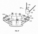
- a tethering system 400 for tethering and reinforcing BOP 41, wellhead 50, and primary conductor 51 is shown.
- Tethering system 400 is substantially the same as tethering system 200 previously described except that tension members 160 are replaced with tension members 460 comprising chains 461, plates 250 are eliminated, tension members 460 are directly coupled to frame 47 with shackle assemblies 251, tensioning systems 220 are replaced with tensioning systems 420, and the tensile preload L is applied to each tension member 146 with a net buoyant subsea buoy 450.
- tensioning systems 420 are chain sheaves.
- Each chain sheave 420 includes a base 421, a pulley or chain wheel 422 rotatably coupled to base 421, and a locking mechanism (not visible in Figure 27 ) coupled to base 421.
- a pin or stabbing member 425 extends downward from base 421 and is releasably locked within a mating receptacle 218b of adapter 216.
- tension members 460 include chains 461, tension members 460 can include chains, wire rope, Dyneema ® rope, or combinations thereof.
- the locking mechanism of chain sheave 420 controls the pay out of tension member 460.
- the locking mechanism has a "locked” position preventing tension member 460 from being paid out from chain wheel 422, and an “unlocked” position allowing tension member 460 to be paid in and paid out from chain wheel 422.
- the locking mechanism of each chain sheave 420 can be any suitable locking mechanism known in the art or any locking mechanism described here (e.g., locking mechanism 150, 324 previously described).
- each tension member 460 has a first or BOP end 460a coupled to frame 47 with a shackle assembly 251 and a second or buoy end 460b coupled to a subsea buoy 450.
- a portion of each tension member 460 between ends 460a, 460b includes chain 461 extending around the corresponding chain wheel 422.
- the tensile preload L is applied to each tension member 460 by unlocking the corresponding locking mechanism and allowing the buoy 450 to pull upward on the tension member 460.
- buoys 450 can be configured to have the buoyancy necessary to induce the desired tensile preloads L.
- the tension member 460 and/or the tension in tension member 460 can be monitored until the desired tensile preload L is applied (i.e., the slack, curve, and catenary in tension member 460 is removed). Once the desired tensile preload L is achieved, the corresponding locking mechanism is transitioned to and maintained in the locked position.
- Chain sheave 420, and more specifically the locking mechanism has a sufficiently high holding capacity (e.g., on the order of hundreds of tons) to prevent the inadvertent pay out of tension member 460 when the locking mechanism is locked and external loads are applied to BOP 41.
- Tethering system 400 is generally deployed and installed in the same manner as tethering system 200 previously described. Once tethering system 400 is installed and tensile preloads L are applied to tension members 460, system 400 stabilizes BOP 41, wellhead 50 and conductor 51 to restrict the lateral/radial movement of BOP 41. As a result, tethering system 400 described herein offers the potential to reduce the stresses induced in BOP 41, tree 40, wellhead 50 and primary conductor 51, improve the strength and fatigue resistance of BOP 41, tree 40, wellhead 50 and primary conductor 51, and improve the bending moment response along primary conductor 51 below the sea floor 12.
- the tensile preload L in each tension member 460 is preferably as low as possible but sufficient to pull out any slack, curve, and catenary in the corresponding member 460.
- the tensile preload in L in each member 460 is preferably the lowest tension that results in that member 460 extending linearly from the corresponding chain wheel 422 to its distal end coupled to BOP 41.
- Such tensile loads L in chains 360 restrict and/or prevent the initial movement and flexing of BOP 41 at the onset of the application of an external loads and/or bending moments, while minimizing the tension in each member 460 before and after the application of the external loads and/or bending moments. The latter consequence minimizes the potential risk of inadvertent damage to BOP 41, tree 40, and LMRP 42 in the event one or more member 460 uncontrollably break.
- tethering systems 100, 200, 400 previously described the distal ends of tensioning members 160, 360, 460 are coupled to frame 47 of BOP 41.
- the BOP does not include a frame.
- alternative means are preferably provided for coupling to the subsea architecture at the highest elevation below the LMRP for the reasons previously described.
- a tethering system 500 for tethering and reinforcing a subsea BOP 522, wellhead 50, and primary conductor 51 (disposed below the sea floor 12) is shown.
- Wellhead 50 and primary conductor 51 are each as previously described, and BOP 522 is the same as BOP 41 previously described except that BOP 522 does not include frame 47.
- Tethering system 500 includes anchors 110 (not visible in Figure 28 ), pile top assemblies 212 mounted to anchors 110, tensioning systems 320, and tensioning members 360, each as previously described. However, since BOP 522 does not include a frame, tethering system 500 also includes an adapter 560 to couple tension members 360 to BOP 522. In particular, adapter 560 is mounted to BOP 522, and distal ends 360a of tension members 360 are coupled to adapter 560. As best shown in Figure 29 , adapter 560 is a spider frame including a central annular hub 561 and a plurality of uniformly circumferentially-spaced rigid arms 562 extending radially outward from hub 561.
- each arm 562 has a first or radially inner end 562a attached to hub 561 and a second or radially outer end 562b distal hub 561.
- Each end 562b comprises a pad eye 563 for coupling to end 360a of a corresponding tension member 360 with a shackle assembly 251 as previously described.
- adapter 560 is mounted to BOP 522 by stabbing a mandrel 523 extending from the upper end of BOP 522 into hub 561. Subsequently, an LMRP (e.g., LMRP 42) is releasably connected to mandrel 523. Thus, adapter 560 is positioned between BOP 522 and the LMRP. With adapter 560 secured to BOP 522, ends 360a of tension members 360 are coupled to pad eyes 563 and the tensile preload L is applied to each tension member 360. Thus, the location of pad eyes 563 define the height H (from the sea floor 12) and the lateral distance D (measured radially and perpendicular from central axis 55). By varying the length of arms 562, the lateral distance D can be adjusted as desired. As previously described, for most subsea applications, lateral distance D is preferably between 5.0 and 15.0 ft., and more preferably about 10.0 ft.
- lateral distance D is preferably between
- tethering system 500 Once tethering system 500 is installed and tensile preloads L are applied with tensioning systems 320. Accordingly, system 500 reinforces BOP 522, wellhead 50 and conductor 51 by restricting the lateral/radial movement of BOP 522. As a result, tethering system 500 described herein offers the potential to reduce the stresses induced in BOP 522, tree 40, wellhead 50 and primary conductor 51, improve the strength and fatigue resistance of BOP 522, tree 40, wellhead 50 and primary conductor 51, and improve the bending moment response along primary conductor 51 below the sea floor 12.
- the tensile preload L in each member 360 is preferably as low as possible but sufficient to pull out any slack, curve, and catenary in the corresponding member 360.
- the tensile preload in L in each member 360 is preferably the lowest tension that results in that member 360 extending linearly from the corresponding chain wheel 322 to its distal end coupled to adapter 560.
- Such tensile loads L in members 360 restrict and/or prevent the initial movement and flexing of BOP 41 at the onset of the application of an external loads and/or bending moments, while minimizing the tension in each member 360 before and after the application of the external loads and/or bending moments. The latter consequence minimizes the potential risk of inadvertent damage to BOP 41, tree 40, and LMRP 42 in the event one or more member 360 uncontrollably break.
- tethering systems 100, 200, 400, 500 described herein apply lateral preloads L l to subsea BOPs (e.g., BOP 41, 522).
- the lateral preloads L l applied to a given BOP are preferably substantially the same and uniformly distributed about the BOP and uniformly applied (i.e., the lateral preloads L l applied to a given BOP are preferably balanced).
- the lateral preloads L l generally seek to maintain the subsea architecture in a generally vertical orientation, reinforce the BOP (e.g., BOP 41, 522), the wellhead (e.g., wellhead 50), the tree (e.g., tree 40) (if provided), and the conductor (e.g., conductor 51) by restricting the lateral/radial movement of the BOP.
- BOP e.g., BOP 41, 522
- the wellhead e.g., wellhead 50
- the tree e.g., tree 40
- the conductor e.g., conductor 51
- tethering systems 100, 200, 400, 500 described herein offer the potential to reduce the stresses induced in the BOP, the tree (if provided), the wellhead and the primary conductor, improve the strength and fatigue resistance of the BOP, the tree (if provided), the wellhead, and the primary conductor, and improve the bending moment response along the primary conductor below the sea floor 12.
- Many variations and modifications of the systems, apparatus, and processes described herein are possible. For example, the relative dimensions of various parts, the materials from which the various parts are made, and other parameters can be varied. Accordingly, the scope of protection is only limited by the claims that follow.
Landscapes
- Life Sciences & Earth Sciences (AREA)
- Engineering & Computer Science (AREA)
- Geology (AREA)
- Mining & Mineral Resources (AREA)
- Physics & Mathematics (AREA)
- Environmental & Geological Engineering (AREA)
- Fluid Mechanics (AREA)
- General Life Sciences & Earth Sciences (AREA)
- Geochemistry & Mineralogy (AREA)
- Earth Drilling (AREA)
- Other Liquid Machine Or Engine Such As Wave Power Use (AREA)
- Laying Of Electric Cables Or Lines Outside (AREA)
Claims (2)
- System (100, 200) zum Anbinden eines Untersee-Absperrventils (Blowout Preventer, BOP) (41), wobei das System (10) Folgendes umfasst:eine Vielzahl von Ankern (110, 210), die um den Untersee-BOP (41) herum angeordnet und am Meeresboden (12) befestigt sind;eine Vielzahl von Spannsystemen (140, 220, 320), wobei ein Spannsystem (140, 220, 320) mit einem oberen Ende jedes Ankers (110, 210) gekoppelt ist;eine Vielzahl von flexiblen Spannelementen (160), wobei sich jedes Spannelement (160) von einem ersten Ende, das mit dem Untersee-BOP (41) gekoppelt ist, zu einem zweiten Ende erstreckt, das mit einem der Spannsysteme (140, 220, 320) gekoppelt ist;wobei jedes Spannsystem (140, 220, 320) dafür konfiguriert ist, eine Zugvorspannung (L) auf eines der Spannelemente (160) aufzubringen;wobei jedes Spannsystem (140, 220, 320) eine Winde (140, 220, 320) ist, die so konfiguriert ist, dass sie das entsprechende Spannelement (160) einfährt und ausfährt; wobei jede Winde (140, 220, 320) eine Spule (141, 222, 322) umfasst, die drehbar mit dem entsprechenden Anker (110, 210) und einem Verriegelungsmechanismus (150, 224, 324) gekoppelt ist, der so konfiguriert ist, dass er ein Ausfahren des entsprechenden Spannelements (160) von der Spule (141, 222, 322) verhindert,wobei die Spule (141, 222, 322) eine Drehachse aufweist.
- System (100, 200) nach Anspruch 1, wobei jeder Verriegelungsmechanismus (150, 224, 324) einen Spulenring (151), der mit der Spule (141, 222, 322) gekoppelt ist, eine Nabe (152), die fest mit dem Anker (110, 210) gekoppelt ist, und einen Verriegelungsring (153) enthält, der verschiebbar an der Nabe (152) angebracht ist;wobei der Spulenring (151) eine Vielzahl von inneren Keilnuten (151a, 153b) enthält, die Nabe (152) eine Vielzahl von äußeren Keilnuten (152a, 153a) enthält und der Sicherungsring (153) eine Vielzahl von äußeren Keilnuten (152a, 153a) und eine Vielzahl von inneren Keilnuten (151a, 153b) enthält;wobei die äußeren Keilnuten (152a, 153a) der Nabe (152) mit den inneren Keilnuten (151a, 153b) des Sicherungsrings (153) zusammenpassen und ineinander greifen;wobei die inneren Keilnuten (151a, 153b) des Spulenrings (151) so konfiguriert sind, dass sie mit der Vielzahl von äußeren Keilnuten (152a, 153a) des Sicherungsrings (153) zusammenpassen und ineinander greifen;wobei der Sicherungsring (153) so konfiguriert ist, dass er sich axial entlang der Nabe (152) zwischen einer entriegelten Position, in der die äußeren Keilnuten (152a, 153a) des Sicherungsrings (153) axial von den inneren Keilnuten (151a, 153 b) des Spulenrings (151) axial beabstandet sind, und einer verriegelten Position, in der die äußeren Nuten (152a, 153a) des Verriegelungsrings (153) mit den inneren Nuten (151a, 153b) des Spulenrings (151) ineinander greifen, bewegt.
Applications Claiming Priority (4)
| Application Number | Priority Date | Filing Date | Title |
|---|---|---|---|
| US201361838709P | 2013-06-24 | 2013-06-24 | |
| EP14739328.4A EP3014052B1 (de) | 2013-06-24 | 2014-06-24 | Systeme und verfahren zur anbindung von untersee-absperrventilen |
| PCT/US2014/043901 WO2014210026A2 (en) | 2013-06-24 | 2014-06-24 | Systems and methods for tethering subsea blowout preventers to enhance the strength and fatigue resistance of subsea wellheads and primary conductors |
| EP17201707.1A EP3312379B1 (de) | 2013-06-24 | 2014-06-24 | System zur anbindung von untersee-absperrventilen |
Related Parent Applications (3)
| Application Number | Title | Priority Date | Filing Date |
|---|---|---|---|
| EP17201707.1A Division EP3312379B1 (de) | 2013-06-24 | 2014-06-24 | System zur anbindung von untersee-absperrventilen |
| EP17201707.1A Division-Into EP3312379B1 (de) | 2013-06-24 | 2014-06-24 | System zur anbindung von untersee-absperrventilen |
| EP14739328.4A Division EP3014052B1 (de) | 2013-06-24 | 2014-06-24 | Systeme und verfahren zur anbindung von untersee-absperrventilen |
Publications (2)
| Publication Number | Publication Date |
|---|---|
| EP3744944A1 EP3744944A1 (de) | 2020-12-02 |
| EP3744944B1 true EP3744944B1 (de) | 2024-12-25 |
Family
ID=51179186
Family Applications (4)
| Application Number | Title | Priority Date | Filing Date |
|---|---|---|---|
| EP20186475.8A Active EP3744944B1 (de) | 2013-06-24 | 2014-06-24 | System zur anbindung von untersee-absperrventilen |
| EP14739328.4A Revoked EP3014052B1 (de) | 2013-06-24 | 2014-06-24 | Systeme und verfahren zur anbindung von untersee-absperrventilen |
| EP24195502.0A Pending EP4474613A3 (de) | 2013-06-24 | 2014-06-24 | Systeme und verfahren zum anbinden von unterwasser-ausblasverhinderern zur erhöhung der festigkeit und ermüdungsbeständigkeit von unterwasserbohrköpfen und primärleitern |
| EP17201707.1A Active EP3312379B1 (de) | 2013-06-24 | 2014-06-24 | System zur anbindung von untersee-absperrventilen |
Family Applications After (3)
| Application Number | Title | Priority Date | Filing Date |
|---|---|---|---|
| EP14739328.4A Revoked EP3014052B1 (de) | 2013-06-24 | 2014-06-24 | Systeme und verfahren zur anbindung von untersee-absperrventilen |
| EP24195502.0A Pending EP4474613A3 (de) | 2013-06-24 | 2014-06-24 | Systeme und verfahren zum anbinden von unterwasser-ausblasverhinderern zur erhöhung der festigkeit und ermüdungsbeständigkeit von unterwasserbohrköpfen und primärleitern |
| EP17201707.1A Active EP3312379B1 (de) | 2013-06-24 | 2014-06-24 | System zur anbindung von untersee-absperrventilen |
Country Status (4)
| Country | Link |
|---|---|
| US (1) | US9359852B2 (de) |
| EP (4) | EP3744944B1 (de) |
| NO (1) | NO3036745T3 (de) |
| WO (1) | WO2014210026A2 (de) |
Families Citing this family (35)
| Publication number | Priority date | Publication date | Assignee | Title |
|---|---|---|---|---|
| US8869899B2 (en) * | 2011-02-21 | 2014-10-28 | Tetra Technologies, Inc. | Method for pulling a crown plug |
| US9284806B2 (en) * | 2013-05-31 | 2016-03-15 | Bp Corporation North America Inc. | Systems and methods for pulling subsea structures |
| US9879396B2 (en) | 2013-06-24 | 2018-01-30 | Trendsetter Vulcan Offshore, Inc. | Systems and methods for tethering subsea structure mounted on a wellhead |
| EP3744944B1 (de) | 2013-06-24 | 2024-12-25 | Trendsetter Vulcan Offshore Inc. | System zur anbindung von untersee-absperrventilen |
| BR112016029232B1 (pt) | 2014-07-01 | 2022-05-03 | Dsm Ip Assets B.V. | Estrutura compreendendo elementos rígidos ligados entre si através de elementos de interligação e uso de fibra polimérica compreendendo polietileno de peso molecular ultraelevado |
| GB2533783B (en) * | 2014-12-29 | 2019-06-05 | Cameron Tech Ltd | Subsea support |
| GB2536106B (en) * | 2015-01-20 | 2018-07-25 | Statoil Petroleum As | Subsea wellhead assembly |
| KR101629197B1 (ko) * | 2015-02-04 | 2016-06-10 | 대우조선해양 주식회사 | 해저 시추시설의 분출방지기 스택의 비상 분리 하중 완화 시스템, 이를 포함하는 분출방지기 스택 및 분출방지기 스택의 재결합 방법 |
| US20170130547A1 (en) * | 2015-11-06 | 2017-05-11 | Vetco Gray, Inc. | Installation assembly for a subsea wellhead |
| US9919771B2 (en) * | 2015-11-18 | 2018-03-20 | Cameron International Corporation | Safety system and method for guiding a dropped suspended load away from equipment and to a safe landing area |
| GB2551236B (en) | 2016-03-08 | 2020-05-13 | Equinor Energy As | Subsea wellhead assembly |
| US9797224B1 (en) * | 2016-10-17 | 2017-10-24 | Ensco International Incorporated | Wellhead stabilizing subsea module |
| GB201622129D0 (en) | 2016-12-23 | 2017-02-08 | Statoil Petroleum As | Subsea assembly modularisation |
| US20200003025A1 (en) * | 2017-02-03 | 2020-01-02 | Trendsetter Vulcan Offshore, Inc. | Systems and methods for tethering a subsea structure |
| GB2566505A (en) * | 2017-09-15 | 2019-03-20 | Expro North Sea Ltd | Subsea well installation and associated methods |
| AU2019100173B4 (en) * | 2017-10-04 | 2019-06-27 | AME Offshore Solutions Pty Ltd | Improvements In or Relating to Subsea Technology |
| BR112020006767B1 (pt) | 2017-10-04 | 2023-05-09 | AME Pty Ltd | Melhorias em ou relacionadas a tecnologia submarina |
| GB2568740B (en) * | 2017-11-27 | 2020-04-22 | Equinor Energy As | Wellhead load relief device |
| GB201719678D0 (en) * | 2017-11-27 | 2018-01-10 | Underwater Novel Tech Limited | Method and appratus for supporting a wellhead |
| NO345282B1 (en) * | 2018-07-23 | 2020-11-30 | Aker Solutions As | Subsea template structure |
| US11473387B2 (en) * | 2019-02-21 | 2022-10-18 | Trendsetter Vulcan Offshore, Inc. | Systems and methods for tethering subsea blow-out-preventers |
| US11549325B2 (en) | 2019-02-21 | 2023-01-10 | Trendsetter Vulcan Offshore, Inc. | Systems and methods for tethering subsea blow-out-preventers |
| NO348252B1 (no) * | 2019-07-11 | 2024-10-28 | Neodrill As | System og fremgangsmåte for stabilisering av stigerør |
| NO347287B1 (en) * | 2019-09-13 | 2023-08-21 | Subseadesign As | A thether line for use in wellhead load relief applications for subsea wells |
| NO20220645A1 (en) * | 2019-11-07 | 2022-06-03 | Aker Solutions As | Subsea wellhead systems and methods |
| GB2589075A (en) | 2019-11-07 | 2021-05-26 | Aker Solutions As | Subsea wellhead systems and methods |
| WO2021091595A1 (en) * | 2019-11-07 | 2021-05-14 | Trendsetter Vulcan Offshore, Inc. | Systems and methods for tethering a subsea structure |
| GB2589077A (en) | 2019-11-07 | 2021-05-26 | Aker Solutions As | Subsea wellhead systems and methods |
| GB2589076A (en) | 2019-11-07 | 2021-05-26 | Aker Solutions As | Subsea wellhead systems and methods |
| US11028663B1 (en) | 2019-11-18 | 2021-06-08 | Trendsetter Engineering, Inc. | Process and apparatus for installing a payload onto a subsea structure |
| GB202020531D0 (en) * | 2020-12-23 | 2021-02-03 | Tla Subsea Ltd | Apparatus, system and method for tethering a subsea assembly |
| NO346898B1 (en) * | 2021-03-08 | 2023-02-20 | Subseadesign As | Linear Rope Tensioner |
| GB2613856B (en) | 2021-12-17 | 2024-05-22 | Aker Solutions As | Subsea wellhead system |
| NO20220828A1 (en) * | 2022-07-26 | 2024-01-29 | Fmc Kongsberg Subsea As | Subsea valve actuator assembly |
| US12221860B2 (en) | 2022-09-23 | 2025-02-11 | Chevron U.S.A. Inc. | Wellhead bracing system |
Citations (16)
| Publication number | Priority date | Publication date | Assignee | Title |
|---|---|---|---|---|
| JPS5786682A (en) | 1980-11-19 | 1982-05-29 | Mitsui Shipbuilding Eng | Laying method of submarine pipe |
| US4408454A (en) | 1980-07-21 | 1983-10-11 | Sea Energy Corporation | Fluid coupled wave generator array with subsea structure |
| US4461460A (en) | 1982-08-10 | 1984-07-24 | Warn Industries, Inc. | Winch |
| US4705320A (en) | 1986-06-10 | 1987-11-10 | Frank J. Zamboni & Co. Inc. | Ice resurfacing machine blade holder |
| US4710061A (en) | 1985-04-12 | 1987-12-01 | Atlantic Richfield Company | Offshore well apparatus and method |
| GB2257405A (en) | 1991-06-27 | 1993-01-13 | Bechtel Ltd | Tether deployment system |
| US5921713A (en) | 1995-03-23 | 1999-07-13 | Kongsberg Offshore A.S | Method for connecting underwater pipelines particularly suitable for great depths and big diameters |
| US20030151037A1 (en) | 2002-02-12 | 2003-08-14 | O'fallon Eugene P. | Winch having internal clutch mechanism |
| US20060162933A1 (en) | 2004-09-01 | 2006-07-27 | Millheim Keith K | System and method of installing and maintaining an offshore exploration and production system having an adjustable buoyancy chamber |
| US20100294505A1 (en) | 2007-10-22 | 2010-11-25 | Andrea Sbordone | System and method for forming connections with a compliant guide |
| US20110229270A1 (en) | 2010-03-16 | 2011-09-22 | Technip France | Installation method of flexible pipe with subsea connector, utilizing a pull down system |
| WO2012065896A2 (en) | 2010-11-16 | 2012-05-24 | Aker Subsea As | Bop lock down |
| WO2012131595A1 (en) | 2011-04-01 | 2012-10-04 | Siguren Ingenierie | Assembly comprising a security apparatus equipping a lifting device, in particular a winch, and system for actuating said apparatus |
| WO2012130315A1 (en) | 2011-03-31 | 2012-10-04 | The Safer Plug Company Limited | A marine riser isolation tool |
| GB2492184A (en) | 2011-06-07 | 2012-12-26 | Michael John Stratton | Spillage containment boom which can be raised and lowered |
| US20130071191A1 (en) | 2010-03-19 | 2013-03-21 | Andrew Buchan | Sub-sea apparatus and operating method |
Family Cites Families (20)
| Publication number | Priority date | Publication date | Assignee | Title |
|---|---|---|---|---|
| US3017934A (en) | 1955-09-30 | 1962-01-23 | Shell Oil Co | Casing support |
| US3424242A (en) | 1956-12-03 | 1969-01-28 | Chevron Res | Method and apparatus for drilling offshore wells |
| US3307624A (en) * | 1963-05-22 | 1967-03-07 | Pan American Petroleum Corp | Load-supporting structure, particularly for marine wells |
| GB2123661B (en) * | 1982-07-22 | 1985-11-06 | Brunswick Corp | Drag for spinning reel |
| US4818146A (en) * | 1985-01-23 | 1989-04-04 | Texhoma Contractors, Inc. | Wellhead and conductor stabilized by a cable and anchor system |
| US5845893A (en) | 1997-03-14 | 1998-12-08 | Bardex Engineering, Inc. | Underwater self-aligning fairlead latch device for mooring a structure at sea |
| US6193441B1 (en) * | 1999-06-24 | 2001-02-27 | Cooper Cameron Corporation | Emergency dump apparatus for buoyancy air tanks on buoyant riser systems |
| US6983714B2 (en) | 2001-06-15 | 2006-01-10 | Technip France | Method of and apparatus for offshore mooring |
| US6752100B2 (en) | 2002-05-28 | 2004-06-22 | Shell Oil Company | Apparatuses and methods of deploying and installing subsea equipment |
| US7104214B2 (en) | 2003-10-03 | 2006-09-12 | Hydralift Amclyde, Inc. | Fairlead with integrated chain stopper |
| US8220405B2 (en) * | 2004-08-06 | 2012-07-17 | Global Innovative Sports Incorporated | Winch system safety device controlled by towrope angle |
| US7458425B2 (en) * | 2004-09-01 | 2008-12-02 | Anadarko Petroleum Corporation | System and method of installing and maintaining an offshore exploration and production system having an adjustable buoyancy chamber |
| US20070017429A1 (en) | 2005-07-21 | 2007-01-25 | Riggs John M | Reverse tensioned mooring system |
| US7891309B2 (en) | 2007-01-24 | 2011-02-22 | Florida Atlantic University | Self contained integrated mooring system |
| NO20072021L (no) * | 2007-04-20 | 2008-10-21 | Seabed Rig As | Fremgangsmate og anordning for intervensjon i en undervanns produksjonsbronn |
| NO331713B1 (no) | 2009-12-15 | 2012-03-05 | Deep Sea Anchors As | Gravitasjonsinstallert anker |
| NO331978B1 (no) * | 2010-06-22 | 2012-05-14 | Neodrill As | Anordning og framgangsmåte for stabilisering av et brønnhode, samt anvendelse av et sugefundament til understøttelse av et brønnhode |
| GB2535667B (en) | 2010-09-22 | 2017-01-18 | Subsea 7 Ltd | Subsea anchoring assembly with an anchor having a mooring line locking member |
| US8770039B2 (en) | 2011-05-23 | 2014-07-08 | Sofec, Inc. | Load monitoring arrangement for chain support |
| EP3744944B1 (de) | 2013-06-24 | 2024-12-25 | Trendsetter Vulcan Offshore Inc. | System zur anbindung von untersee-absperrventilen |
-
2014
- 2014-06-24 EP EP20186475.8A patent/EP3744944B1/de active Active
- 2014-06-24 EP EP14739328.4A patent/EP3014052B1/de not_active Revoked
- 2014-06-24 EP EP24195502.0A patent/EP4474613A3/de active Pending
- 2014-06-24 US US14/313,633 patent/US9359852B2/en active Active
- 2014-06-24 EP EP17201707.1A patent/EP3312379B1/de active Active
- 2014-06-24 WO PCT/US2014/043901 patent/WO2014210026A2/en not_active Ceased
- 2014-08-14 NO NO14838642A patent/NO3036745T3/no unknown
Patent Citations (16)
| Publication number | Priority date | Publication date | Assignee | Title |
|---|---|---|---|---|
| US4408454A (en) | 1980-07-21 | 1983-10-11 | Sea Energy Corporation | Fluid coupled wave generator array with subsea structure |
| JPS5786682A (en) | 1980-11-19 | 1982-05-29 | Mitsui Shipbuilding Eng | Laying method of submarine pipe |
| US4461460A (en) | 1982-08-10 | 1984-07-24 | Warn Industries, Inc. | Winch |
| US4710061A (en) | 1985-04-12 | 1987-12-01 | Atlantic Richfield Company | Offshore well apparatus and method |
| US4705320A (en) | 1986-06-10 | 1987-11-10 | Frank J. Zamboni & Co. Inc. | Ice resurfacing machine blade holder |
| GB2257405A (en) | 1991-06-27 | 1993-01-13 | Bechtel Ltd | Tether deployment system |
| US5921713A (en) | 1995-03-23 | 1999-07-13 | Kongsberg Offshore A.S | Method for connecting underwater pipelines particularly suitable for great depths and big diameters |
| US20030151037A1 (en) | 2002-02-12 | 2003-08-14 | O'fallon Eugene P. | Winch having internal clutch mechanism |
| US20060162933A1 (en) | 2004-09-01 | 2006-07-27 | Millheim Keith K | System and method of installing and maintaining an offshore exploration and production system having an adjustable buoyancy chamber |
| US20100294505A1 (en) | 2007-10-22 | 2010-11-25 | Andrea Sbordone | System and method for forming connections with a compliant guide |
| US20110229270A1 (en) | 2010-03-16 | 2011-09-22 | Technip France | Installation method of flexible pipe with subsea connector, utilizing a pull down system |
| US20130071191A1 (en) | 2010-03-19 | 2013-03-21 | Andrew Buchan | Sub-sea apparatus and operating method |
| WO2012065896A2 (en) | 2010-11-16 | 2012-05-24 | Aker Subsea As | Bop lock down |
| WO2012130315A1 (en) | 2011-03-31 | 2012-10-04 | The Safer Plug Company Limited | A marine riser isolation tool |
| WO2012131595A1 (en) | 2011-04-01 | 2012-10-04 | Siguren Ingenierie | Assembly comprising a security apparatus equipping a lifting device, in particular a winch, and system for actuating said apparatus |
| GB2492184A (en) | 2011-06-07 | 2012-12-26 | Michael John Stratton | Spillage containment boom which can be raised and lowered |
Non-Patent Citations (11)
| Title |
|---|
| ANONYMOUS: "Manual transmission", WIKIPEDIA, THE FREE ENCYCLOPEDIA, 18 June 2013 (2013-06-18), XP055675100, Retrieved from the Internet <URL:https://en.wikipedia.org/w/index.php?title=Manual_transmission&oldid=560409361> [retrieved on 20200310] |
| ANONYMOUS: "Winch", WIKIPEDIA, THE FREE ENCYCLOPEDIA, 29 May 2013 (2013-05-29), XP055675095, [retrieved on 20200310] |
| ASGEIR DAHL LIEN LIEN: "Methods to Improve Subsea Wellhead Fatigue Life (thesis)", NORWEGIAN UNIVERSITY OF SCIENCE AND TECHNOLOGY, 17 December 2009 (2009-12-17), Norwegian University of Science and Technology , pages FP - 42, XP055598118, [retrieved on 20190620] |
| D23 - DYP MAGAZINE: "SUBSEA-BRANSJENS FREMTID", 2009, FFU THE ASSOCIATION FOR REMOTELY CONTROLLED UNDERWATER TECHNOLOGY |
| GRASER J A: "SPE 23051 Continued Development and Field Testing of the Subsea Wireline Winch System", PROCEEDINGS OF OFFSHORE EUROPE ’91 (SPE OFFSHORE EUROPE CONFERENCE, 3 September 1991 (1991-09-03), pages 211 - 218, XP093320827 |
| INALL M.E., MELDRUM D.T., PROVOST P.G., MERCER D.J.L., GRIFFITHS C.R., PEPPE O., VASSIE I.M., THOMSON W.T.: "HOMER: early results from a novel seabed-resident water column profiler", OCEANS 2005 - EUROPE BREST, FRANCE 20-23 JUNE 2005, PISCATAWAY, NJ, USA,IEEE, US, vol. 2, 20 June 2005 (2005-06-20) - 23 June 2005 (2005-06-23), US , pages 1252 - 1255 Vol. 2, XP010838332, ISBN: 978-0-7803-9103-1 |
| J. GREEN: "BOMIS, Bottom-Mounted Instrumentation System, a new concept in deployment of instrumentation into the sea", ENGINEERING IN THE OCEAN ENVIRONMENT, OCEAN 73 - IEEE INTERNATIONAL CONFERENCE ON, IEEE, PISCATAWAY, NJ, USA, 25 September 1973 (1973-09-25), Piscataway, NJ, USA , pages 379 - 383, XP031635491 |
| JUHYUN PYO ; SON-CHEOL YU ; JONG-CHUN PARK ; SUNG-CHUL PARK: "Development of a robotic anchoring system for underwater vehicle under water current", OCEANS, 2012 - YEOSU, IEEE, 21 May 2012 (2012-05-21), pages 1 - 5, XP032219342, ISBN: 978-1-4577-2089-5, DOI: 10.1109/OCEANS-Yeosu.2012.6263395 |
| MARK RANDOLPH, SUSAN GOURVENEC: "Offshore Geotechnical Engineering", 1 January 2011, SPON PRESS, ISBN: 978-0-415-47744-4, article MARK RANDOLPH, SUSAN GOURVENEC: "7 Anchoring systems", pages: 308 - 360, XP009564363, DOI: 10.1201/9781315272474 |
| SON-CHEOL YU ; JU HYUN ; DAE-YOUNG KIM ; MYEONG-KWAN PARK ; JU-HYUN PYO ; PETER C. CHO ; CHANG-SOON HWANG: "The development of multi-functional autonomous amphibious vehicle", UNDERWATER TECHNOLOGY (UT), 2011 IEEE SYMPOSIUM ON AND 2011 WORKSHOP ON SCIENTIFIC USE OF SUBMARINE CABLES AND RELATED TECHNOLOGIES (SSC), IEEE, 5 April 2011 (2011-04-05), pages 1 - 6, XP031876611, ISBN: 978-1-4577-0165-8, DOI: 10.1109/UT.2011.5774088 |
| VERNON ASPER ; SCOTT GALLAGER ; KEITH VON DER HEYDT ; STEVEN LERNER ; ANDREW GIRARD ; KENNETH PEAL ; EMILY MILLER ; GLENN MCDONALD: "Design and Construction of a Polar Remote Interactive Marine Observatory (PRIMO)", OCEANS 2006, IEEE, PI, 1 September 2006 (2006-09-01), Pi , pages 1 - 3, XP031046422, ISBN: 978-1-4244-0114-7 |
Also Published As
| Publication number | Publication date |
|---|---|
| EP3014052A2 (de) | 2016-05-04 |
| US20140374115A1 (en) | 2014-12-25 |
| EP4474613A3 (de) | 2025-03-05 |
| NO3036745T3 (de) | 2018-09-01 |
| US9359852B2 (en) | 2016-06-07 |
| WO2014210026A2 (en) | 2014-12-31 |
| WO2014210026A3 (en) | 2015-04-30 |
| EP3312379A1 (de) | 2018-04-25 |
| EP4474613A2 (de) | 2024-12-11 |
| EP3312379B1 (de) | 2024-11-20 |
| EP3744944A1 (de) | 2020-12-02 |
| EP3014052B1 (de) | 2017-12-13 |
Similar Documents
| Publication | Publication Date | Title |
|---|---|---|
| EP3744944B1 (de) | System zur anbindung von untersee-absperrventilen | |
| US10577768B2 (en) | Systems and methods for tethering subsea structure mounted on a wellhead | |
| US20140374116A1 (en) | Systems and Methods for Tethering Subsea Wellheads to Enhance the Fatigue Resistance of Subsea Wellheads and Primary Conductors | |
| EP3577307B1 (de) | Systeme und verfahren zum festmachen einer unterwasserstruktur | |
| US9284806B2 (en) | Systems and methods for pulling subsea structures | |
| US9587466B2 (en) | Cementing system for riserless abandonment operation | |
| US9488024B2 (en) | Annulus cementing tool for subsea abandonment operation | |
| EP2326793B1 (de) | Hochdruckhülse für doppelbohrungshochdrucksteigrohr | |
| US9260931B2 (en) | Riser breakaway connection and intervention coupling device | |
| US20140374113A1 (en) | Systems and Methods for Bracing Subsea Wellheads to Enhance the Fatigue Resistance of Subsea Wellheads and Primary Conductors | |
| US9353602B2 (en) | Riser weak link | |
| US20170191334A1 (en) | Systems and methods for engaging subsea equipment | |
| US11933117B2 (en) | Tubular compensation method | |
| EP3682084B1 (de) | Zugspannungsanordnung für unterwassereruptionskreuz | |
| BR112019015560B1 (pt) | Sistema e método para fixação de um preventor de erupção submarino |
Legal Events
| Date | Code | Title | Description |
|---|---|---|---|
| PUAI | Public reference made under article 153(3) epc to a published international application that has entered the european phase |
Free format text: ORIGINAL CODE: 0009012 |
|
| STAA | Information on the status of an ep patent application or granted ep patent |
Free format text: STATUS: THE APPLICATION HAS BEEN PUBLISHED |
|
| AC | Divisional application: reference to earlier application |
Ref document number: 3312379 Country of ref document: EP Kind code of ref document: P Ref document number: 3014052 Country of ref document: EP Kind code of ref document: P |
|
| AK | Designated contracting states |
Kind code of ref document: A1 Designated state(s): AL AT BE BG CH CY CZ DE DK EE ES FI FR GB GR HR HU IE IS IT LI LT LU LV MC MK MT NL NO PL PT RO RS SE SI SK SM TR |
|
| STAA | Information on the status of an ep patent application or granted ep patent |
Free format text: STATUS: REQUEST FOR EXAMINATION WAS MADE |
|
| 17P | Request for examination filed |
Effective date: 20210602 |
|
| RBV | Designated contracting states (corrected) |
Designated state(s): AL AT BE BG CH CY CZ DE DK EE ES FI FR GB GR HR HU IE IS IT LI LT LU LV MC MK MT NL NO PL PT RO RS SE SI SK SM TR |
|
| STAA | Information on the status of an ep patent application or granted ep patent |
Free format text: STATUS: EXAMINATION IS IN PROGRESS |
|
| 17Q | First examination report despatched |
Effective date: 20220217 |
|
| GRAP | Despatch of communication of intention to grant a patent |
Free format text: ORIGINAL CODE: EPIDOSNIGR1 |
|
| STAA | Information on the status of an ep patent application or granted ep patent |
Free format text: STATUS: GRANT OF PATENT IS INTENDED |
|
| INTG | Intention to grant announced |
Effective date: 20240723 |
|
| GRAS | Grant fee paid |
Free format text: ORIGINAL CODE: EPIDOSNIGR3 |
|
| GRAA | (expected) grant |
Free format text: ORIGINAL CODE: 0009210 |
|
| STAA | Information on the status of an ep patent application or granted ep patent |
Free format text: STATUS: THE PATENT HAS BEEN GRANTED |
|
| AC | Divisional application: reference to earlier application |
Ref document number: 3014052 Country of ref document: EP Kind code of ref document: P Ref document number: 3312379 Country of ref document: EP Kind code of ref document: P |
|
| AK | Designated contracting states |
Kind code of ref document: B1 Designated state(s): AL AT BE BG CH CY CZ DE DK EE ES FI FR GB GR HR HU IE IS IT LI LT LU LV MC MK MT NL NO PL PT RO RS SE SI SK SM TR |
|
| REG | Reference to a national code |
Ref country code: GB Ref legal event code: FG4D |
|
| REG | Reference to a national code |
Ref country code: CH Ref legal event code: EP |
|
| REG | Reference to a national code |
Ref country code: DE Ref legal event code: R096 Ref document number: 602014091391 Country of ref document: DE |
|
| REG | Reference to a national code |
Ref country code: IE Ref legal event code: FG4D |
|
| REG | Reference to a national code |
Ref country code: LT Ref legal event code: MG9D |
|
| PG25 | Lapsed in a contracting state [announced via postgrant information from national office to epo] |
Ref country code: HR Free format text: LAPSE BECAUSE OF FAILURE TO SUBMIT A TRANSLATION OF THE DESCRIPTION OR TO PAY THE FEE WITHIN THE PRESCRIBED TIME-LIMIT Effective date: 20241225 |
|
| PG25 | Lapsed in a contracting state [announced via postgrant information from national office to epo] |
Ref country code: FI Free format text: LAPSE BECAUSE OF FAILURE TO SUBMIT A TRANSLATION OF THE DESCRIPTION OR TO PAY THE FEE WITHIN THE PRESCRIBED TIME-LIMIT Effective date: 20241225 |
|
| PG25 | Lapsed in a contracting state [announced via postgrant information from national office to epo] |
Ref country code: BG Free format text: LAPSE BECAUSE OF FAILURE TO SUBMIT A TRANSLATION OF THE DESCRIPTION OR TO PAY THE FEE WITHIN THE PRESCRIBED TIME-LIMIT Effective date: 20241225 |
|
| PG25 | Lapsed in a contracting state [announced via postgrant information from national office to epo] |
Ref country code: GR Free format text: LAPSE BECAUSE OF FAILURE TO SUBMIT A TRANSLATION OF THE DESCRIPTION OR TO PAY THE FEE WITHIN THE PRESCRIBED TIME-LIMIT Effective date: 20250326 Ref country code: LV Free format text: LAPSE BECAUSE OF FAILURE TO SUBMIT A TRANSLATION OF THE DESCRIPTION OR TO PAY THE FEE WITHIN THE PRESCRIBED TIME-LIMIT Effective date: 20241225 |
|
| PG25 | Lapsed in a contracting state [announced via postgrant information from national office to epo] |
Ref country code: RS Free format text: LAPSE BECAUSE OF FAILURE TO SUBMIT A TRANSLATION OF THE DESCRIPTION OR TO PAY THE FEE WITHIN THE PRESCRIBED TIME-LIMIT Effective date: 20250325 |
|
| REG | Reference to a national code |
Ref country code: NL Ref legal event code: MP Effective date: 20241225 |
|
| PG25 | Lapsed in a contracting state [announced via postgrant information from national office to epo] |
Ref country code: NL Free format text: LAPSE BECAUSE OF FAILURE TO SUBMIT A TRANSLATION OF THE DESCRIPTION OR TO PAY THE FEE WITHIN THE PRESCRIBED TIME-LIMIT Effective date: 20241225 |
|
| REG | Reference to a national code |
Ref country code: AT Ref legal event code: MK05 Ref document number: 1754305 Country of ref document: AT Kind code of ref document: T Effective date: 20241225 |
|
| PG25 | Lapsed in a contracting state [announced via postgrant information from national office to epo] |
Ref country code: SM Free format text: LAPSE BECAUSE OF FAILURE TO SUBMIT A TRANSLATION OF THE DESCRIPTION OR TO PAY THE FEE WITHIN THE PRESCRIBED TIME-LIMIT Effective date: 20241225 |
|
| PG25 | Lapsed in a contracting state [announced via postgrant information from national office to epo] |
Ref country code: PL Free format text: LAPSE BECAUSE OF FAILURE TO SUBMIT A TRANSLATION OF THE DESCRIPTION OR TO PAY THE FEE WITHIN THE PRESCRIBED TIME-LIMIT Effective date: 20241225 |
|
| PG25 | Lapsed in a contracting state [announced via postgrant information from national office to epo] |
Ref country code: ES Free format text: LAPSE BECAUSE OF FAILURE TO SUBMIT A TRANSLATION OF THE DESCRIPTION OR TO PAY THE FEE WITHIN THE PRESCRIBED TIME-LIMIT Effective date: 20241225 |
|
| PGFP | Annual fee paid to national office [announced via postgrant information from national office to epo] |
Ref country code: GB Payment date: 20250627 Year of fee payment: 12 |
|
| PG25 | Lapsed in a contracting state [announced via postgrant information from national office to epo] |
Ref country code: IS Free format text: LAPSE BECAUSE OF FAILURE TO SUBMIT A TRANSLATION OF THE DESCRIPTION OR TO PAY THE FEE WITHIN THE PRESCRIBED TIME-LIMIT Effective date: 20250425 |
|
| PGFP | Annual fee paid to national office [announced via postgrant information from national office to epo] |
Ref country code: NO Payment date: 20250627 Year of fee payment: 12 |
|
| PG25 | Lapsed in a contracting state [announced via postgrant information from national office to epo] |
Ref country code: PT Free format text: LAPSE BECAUSE OF FAILURE TO SUBMIT A TRANSLATION OF THE DESCRIPTION OR TO PAY THE FEE WITHIN THE PRESCRIBED TIME-LIMIT Effective date: 20250428 |
|
| PG25 | Lapsed in a contracting state [announced via postgrant information from national office to epo] |
Ref country code: EE Free format text: LAPSE BECAUSE OF FAILURE TO SUBMIT A TRANSLATION OF THE DESCRIPTION OR TO PAY THE FEE WITHIN THE PRESCRIBED TIME-LIMIT Effective date: 20241225 |
|
| PG25 | Lapsed in a contracting state [announced via postgrant information from national office to epo] |
Ref country code: AT Free format text: LAPSE BECAUSE OF FAILURE TO SUBMIT A TRANSLATION OF THE DESCRIPTION OR TO PAY THE FEE WITHIN THE PRESCRIBED TIME-LIMIT Effective date: 20241225 Ref country code: RO Free format text: LAPSE BECAUSE OF FAILURE TO SUBMIT A TRANSLATION OF THE DESCRIPTION OR TO PAY THE FEE WITHIN THE PRESCRIBED TIME-LIMIT Effective date: 20241225 |
|
| PG25 | Lapsed in a contracting state [announced via postgrant information from national office to epo] |
Ref country code: SK Free format text: LAPSE BECAUSE OF FAILURE TO SUBMIT A TRANSLATION OF THE DESCRIPTION OR TO PAY THE FEE WITHIN THE PRESCRIBED TIME-LIMIT Effective date: 20241225 |
|
| PG25 | Lapsed in a contracting state [announced via postgrant information from national office to epo] |
Ref country code: CZ Free format text: LAPSE BECAUSE OF FAILURE TO SUBMIT A TRANSLATION OF THE DESCRIPTION OR TO PAY THE FEE WITHIN THE PRESCRIBED TIME-LIMIT Effective date: 20241225 |
|
| PG25 | Lapsed in a contracting state [announced via postgrant information from national office to epo] |
Ref country code: IT Free format text: LAPSE BECAUSE OF FAILURE TO SUBMIT A TRANSLATION OF THE DESCRIPTION OR TO PAY THE FEE WITHIN THE PRESCRIBED TIME-LIMIT Effective date: 20241225 |
|
| PG25 | Lapsed in a contracting state [announced via postgrant information from national office to epo] |
Ref country code: SE Free format text: LAPSE BECAUSE OF FAILURE TO SUBMIT A TRANSLATION OF THE DESCRIPTION OR TO PAY THE FEE WITHIN THE PRESCRIBED TIME-LIMIT Effective date: 20241225 |
|
| REG | Reference to a national code |
Ref country code: DE Ref legal event code: R026 Ref document number: 602014091391 Country of ref document: DE |
|
| PLBI | Opposition filed |
Free format text: ORIGINAL CODE: 0009260 |
|
| REG | Reference to a national code |
Ref country code: CH Ref legal event code: L10 Free format text: ST27 STATUS EVENT CODE: U-0-0-L10-L00 (AS PROVIDED BY THE NATIONAL OFFICE) Effective date: 20251006 |
|
| PG25 | Lapsed in a contracting state [announced via postgrant information from national office to epo] |
Ref country code: DK Free format text: LAPSE BECAUSE OF FAILURE TO SUBMIT A TRANSLATION OF THE DESCRIPTION OR TO PAY THE FEE WITHIN THE PRESCRIBED TIME-LIMIT Effective date: 20241225 |
|
| PLAX | Notice of opposition and request to file observation + time limit sent |
Free format text: ORIGINAL CODE: EPIDOSNOBS2 |
|
| 26 | Opposition filed |
Opponent name: SUBSEA TOOLING SERVICES (UK) LIMITED Effective date: 20250924 Opponent name: EQUINOR ENERGY AS Effective date: 20250924 |
|
| REG | Reference to a national code |
Ref country code: CH Ref legal event code: H13 Free format text: ST27 STATUS EVENT CODE: U-0-0-H10-H13 (AS PROVIDED BY THE NATIONAL OFFICE) Effective date: 20260127 |
|
| PG25 | Lapsed in a contracting state [announced via postgrant information from national office to epo] |
Ref country code: MC Free format text: LAPSE BECAUSE OF FAILURE TO SUBMIT A TRANSLATION OF THE DESCRIPTION OR TO PAY THE FEE WITHIN THE PRESCRIBED TIME-LIMIT Effective date: 20241225 |