EP3744878A1 - Flame-retardant fiber bundle and method for manufacturing carbon fiber bundle - Google Patents
Flame-retardant fiber bundle and method for manufacturing carbon fiber bundle Download PDFInfo
- Publication number
- EP3744878A1 EP3744878A1 EP19744501.8A EP19744501A EP3744878A1 EP 3744878 A1 EP3744878 A1 EP 3744878A1 EP 19744501 A EP19744501 A EP 19744501A EP 3744878 A1 EP3744878 A1 EP 3744878A1
- Authority
- EP
- European Patent Office
- Prior art keywords
- fiber bundle
- roller
- rollers
- stabilized
- carbon fiber
- Prior art date
- Legal status (The legal status is an assumption and is not a legal conclusion. Google has not performed a legal analysis and makes no representation as to the accuracy of the status listed.)
- Granted
Links
Images


Classifications
-
- D—TEXTILES; PAPER
- D01—NATURAL OR MAN-MADE THREADS OR FIBRES; SPINNING
- D01D—MECHANICAL METHODS OR APPARATUS IN THE MANUFACTURE OF ARTIFICIAL FILAMENTS, THREADS, FIBRES, BRISTLES OR RIBBONS
- D01D10/00—Physical treatment of artificial filaments or the like during manufacture, i.e. during a continuous production process before the filaments have been collected
- D01D10/02—Heat treatment
-
- B—PERFORMING OPERATIONS; TRANSPORTING
- B65—CONVEYING; PACKING; STORING; HANDLING THIN OR FILAMENTARY MATERIAL
- B65H—HANDLING THIN OR FILAMENTARY MATERIAL, e.g. SHEETS, WEBS, CABLES
- B65H57/00—Guides for filamentary materials; Supports therefor
- B65H57/14—Pulleys, rollers, or rotary bars
-
- D—TEXTILES; PAPER
- D01—NATURAL OR MAN-MADE THREADS OR FIBRES; SPINNING
- D01D—MECHANICAL METHODS OR APPARATUS IN THE MANUFACTURE OF ARTIFICIAL FILAMENTS, THREADS, FIBRES, BRISTLES OR RIBBONS
- D01D11/00—Other features of manufacture
- D01D11/02—Opening bundles to space the threads or filaments from one another
-
- D—TEXTILES; PAPER
- D01—NATURAL OR MAN-MADE THREADS OR FIBRES; SPINNING
- D01F—CHEMICAL FEATURES IN THE MANUFACTURE OF ARTIFICIAL FILAMENTS, THREADS, FIBRES, BRISTLES OR RIBBONS; APPARATUS SPECIALLY ADAPTED FOR THE MANUFACTURE OF CARBON FILAMENTS
- D01F6/00—Monocomponent artificial filaments or the like of synthetic polymers; Manufacture thereof
- D01F6/02—Monocomponent artificial filaments or the like of synthetic polymers; Manufacture thereof from homopolymers obtained by reactions only involving carbon-to-carbon unsaturated bonds
- D01F6/18—Monocomponent artificial filaments or the like of synthetic polymers; Manufacture thereof from homopolymers obtained by reactions only involving carbon-to-carbon unsaturated bonds from polymers of unsaturated nitriles, e.g. polyacrylonitrile, polyvinylidene cyanide
-
- D—TEXTILES; PAPER
- D01—NATURAL OR MAN-MADE THREADS OR FIBRES; SPINNING
- D01F—CHEMICAL FEATURES IN THE MANUFACTURE OF ARTIFICIAL FILAMENTS, THREADS, FIBRES, BRISTLES OR RIBBONS; APPARATUS SPECIALLY ADAPTED FOR THE MANUFACTURE OF CARBON FILAMENTS
- D01F9/00—Artificial filaments or the like of other substances; Manufacture thereof; Apparatus specially adapted for the manufacture of carbon filaments
- D01F9/08—Artificial filaments or the like of other substances; Manufacture thereof; Apparatus specially adapted for the manufacture of carbon filaments of inorganic material
- D01F9/12—Carbon filaments; Apparatus specially adapted for the manufacture thereof
- D01F9/14—Carbon filaments; Apparatus specially adapted for the manufacture thereof by decomposition of organic filaments
- D01F9/20—Carbon filaments; Apparatus specially adapted for the manufacture thereof by decomposition of organic filaments from polyaddition, polycondensation or polymerisation products
- D01F9/21—Carbon filaments; Apparatus specially adapted for the manufacture thereof by decomposition of organic filaments from polyaddition, polycondensation or polymerisation products from macromolecular compounds obtained by reactions only involving carbon-to-carbon unsaturated bonds
- D01F9/22—Carbon filaments; Apparatus specially adapted for the manufacture thereof by decomposition of organic filaments from polyaddition, polycondensation or polymerisation products from macromolecular compounds obtained by reactions only involving carbon-to-carbon unsaturated bonds from polyacrylonitriles
- D01F9/225—Carbon filaments; Apparatus specially adapted for the manufacture thereof by decomposition of organic filaments from polyaddition, polycondensation or polymerisation products from macromolecular compounds obtained by reactions only involving carbon-to-carbon unsaturated bonds from polyacrylonitriles from stabilised polyacrylonitriles
-
- D—TEXTILES; PAPER
- D01—NATURAL OR MAN-MADE THREADS OR FIBRES; SPINNING
- D01F—CHEMICAL FEATURES IN THE MANUFACTURE OF ARTIFICIAL FILAMENTS, THREADS, FIBRES, BRISTLES OR RIBBONS; APPARATUS SPECIALLY ADAPTED FOR THE MANUFACTURE OF CARBON FILAMENTS
- D01F9/00—Artificial filaments or the like of other substances; Manufacture thereof; Apparatus specially adapted for the manufacture of carbon filaments
- D01F9/08—Artificial filaments or the like of other substances; Manufacture thereof; Apparatus specially adapted for the manufacture of carbon filaments of inorganic material
- D01F9/12—Carbon filaments; Apparatus specially adapted for the manufacture thereof
- D01F9/14—Carbon filaments; Apparatus specially adapted for the manufacture thereof by decomposition of organic filaments
- D01F9/32—Apparatus therefor
- D01F9/328—Apparatus therefor for manufacturing filaments from polyaddition, polycondensation, or polymerisation products
-
- D—TEXTILES; PAPER
- D02—YARNS; MECHANICAL FINISHING OF YARNS OR ROPES; WARPING OR BEAMING
- D02J—FINISHING OR DRESSING OF FILAMENTS, YARNS, THREADS, CORDS, ROPES OR THE LIKE
- D02J13/00—Heating or cooling the yarn, thread, cord, rope, or the like, not specific to any one of the processes provided for in this subclass
- D02J13/001—Heating or cooling the yarn, thread, cord, rope, or the like, not specific to any one of the processes provided for in this subclass in a tube or vessel
-
- D—TEXTILES; PAPER
- D02—YARNS; MECHANICAL FINISHING OF YARNS OR ROPES; WARPING OR BEAMING
- D02J—FINISHING OR DRESSING OF FILAMENTS, YARNS, THREADS, CORDS, ROPES OR THE LIKE
- D02J13/00—Heating or cooling the yarn, thread, cord, rope, or the like, not specific to any one of the processes provided for in this subclass
- D02J13/005—Heating or cooling the yarn, thread, cord, rope, or the like, not specific to any one of the processes provided for in this subclass by contact with at least one rotating roll
-
- B—PERFORMING OPERATIONS; TRANSPORTING
- B65—CONVEYING; PACKING; STORING; HANDLING THIN OR FILAMENTARY MATERIAL
- B65H—HANDLING THIN OR FILAMENTARY MATERIAL, e.g. SHEETS, WEBS, CABLES
- B65H2701/00—Handled material; Storage means
- B65H2701/30—Handled filamentary material
- B65H2701/31—Textiles threads or artificial strands of filaments
-
- D—TEXTILES; PAPER
- D10—INDEXING SCHEME ASSOCIATED WITH SUBLASSES OF SECTION D, RELATING TO TEXTILES
- D10B—INDEXING SCHEME ASSOCIATED WITH SUBLASSES OF SECTION D, RELATING TO TEXTILES
- D10B2321/00—Fibres made from polymers obtained by reactions only involving carbon-to-carbon unsaturated bonds
- D10B2321/10—Fibres made from polymers obtained by reactions only involving carbon-to-carbon unsaturated bonds polymers of unsaturated nitriles, e.g. polyacrylonitrile, polyvinylidene cyanide
Definitions
- the present invention relates to a method for manufacturing a stabilized fiber bundle, the method being intended for obtaining a high-strength carbon fiber bundle by the suppression of adhesion between the single fibers in a stabilization process, and a method for manufacturing a carbon fiber bundle.
- Carbon fiber bundles have specific strength and specific modulus superior to those of other fibers, and are widely used as reinforcing materials for composite materials not only in sports and aerospace applications but also in general industrial applications such as automobiles, wind turbines, and pressure vessels. Particularly in the fields of aircraft and automobiles in which weight reduction of airframes and vehicle bodies is strongly demanded from the viewpoint of environment and cost, there is a high demand for carbon fiber bundles, and still higher performance of carbon fiber bundles has been demanded recently. In particular, carbon fiber bundles having high tensile strength have been demanded.
- the tensile strength of a carbon fiber bundle depends on the tensile strength of a polyacrylonitrile precursor that is a raw material of the carbon fiber bundle. It is known that factors that greatly affect the tensile strength of a carbon fiber bundle are flaws and toughness.
- the flaws include damages and voids that may occur in single fibers due to contact with and adhesion of foreign substances such as dust and metals, damages on the surface of single fibers due to adhesion between the single fibers, and damages of the carbon fiber bundle itself due to, for example, abrasion with rollers, all of which may occur in the manufacturing process of the carbon fiber bundle.
- the carbon fiber bundle may be reduced in the tensile strength with an increase of the size and number of the flaws.
- examples of the factor of the toughness include a skin-core structural difference of the single fibers that constitute the stabilized fiber bundle due to a difference in heat treatment between the surface layer and the inner layer of the single fibers in the stabilization process. If there is a large difference in heat treatment between the surface layer and the inner layer, the stabilized fiber bundle may have reduced toughness, and the carbon fiber bundle tends to have reduced tensile strength.
- a polyacrylonitrile carbon fiber bundle is manufactured by a method including heating a polyacrylonitrile precursor fiber bundle in an oxidizing gas atmosphere at 200 to 300°C to give a stabilized fiber bundle, and then heating the stabilized fiber bundle in an inert gas atmosphere at 1000°C or more.
- the polyacrylonitrile precursor fiber bundle usually includes 1,000 to 60,000 single fibers. Since the polyacrylonitrile precursor fiber bundle is combustible, in the stabilization process, the single fibers may adhere to each other during the stabilization of the polyacrylonitrile precursor fiber bundle in an oxidizing atmosphere.
- Patent Document 1 discloses that carbonaceous fibers fused together due to thermal alteration or the like of the fibers themselves are caused to run on a plurality of cylindrical rollers having center axes intersecting with each other to peel the carbonaceous fibers in a state of being displaced laterally on the rollers, whereby the carbonaceous fibers turn supple and the dispersibility of single yarns in a matrix resin is improved.
- Patent Document 2 discloses that during the convergence of pitch-based carbon fibers, the "fusion” in which a plurality of fibers are integrated with each other to cause a reduction of the tensile strength, or the “agglutination” in which a plurality of fibers are integrated with each other but can be easily separated into original fibers may occur, and the fiber bundle is spread after the precarbonization by being passed between ceramic rollers to prevent the reduction of the tensile strength due to convergence.
- Patent Document 3 discloses that in stabilizing a polyacrylonitrile precursor fiber bundle in an oxidizing atmosphere, the fiber bundle is passed on a grooved roller and then spread with a flat roller, that is, the flatness of the running fiber bundle is changed and then the fiber bundle is heat-treated, whereby the accumulation of reaction heat during the stabilization treatment is suppressed, and the structural difference between the surface layer and the inner layer of the single fibers due to a difference in the infusibilization reaction rate is reduced to improve the tensile strength of the carbon fiber.
- Patent Document 4 discloses a method for manufacturing a high-strength carbon fiber, the method including passing a precursor fiber bundle on a plurality of solid guide bars to spread the precursor fiber bundle at the level of single fibers, and then stabilizing the spread precursor fiber bundle, thereby suppressing the adhesion between the single fibers.
- Patent Document 5 discloses a method for manufacturing a stabilized fiber bundle, the method including, in order to prevent the adhesion between the single fibers on a folding roller due to a high surface temperature of the folding roller during the stabilization treatment of a precursor fiber bundle, blowing the air at 15 to 30°C to the fiber bundle at a wind speed of 50 to 150 m/s before the precursor fiber bundle comes into contact with the roller to deform and cool the precursor fiber bundle.
- Patent Document 6 discloses a method for manufacturing a stabilized fiber bundle, the method including subjecting a fiber bundle during the stabilization treatment to the spreading treatment and then to the stabilization treatment again, in order to solve, during the stabilization treatment, the agglutination between the single fibers that may occur at the surface of the single fibers in the fiber bundle obtained by heat-treating an acrylonitrile fiber bundle by stabilization.
- Patent Documents 1 and 2 are intended for a pitch-based carbon fiber bundle, and the fusion or agglutination between the single fibers that may occur during the thermal alteration or convergence of the carbon fiber bundle is solved by passing the carbon fiber bundle on a plurality of rollers for peeling or spreading treatment to separate the single fibers.
- the fiber bundle has a tensile strength of 350 to 360 kgf/mm 2 , which is not so sufficiently high compared to the tensile strength of a polyacrylonitrile carbon fiber bundle.
- the carbon fiber bundle has high tensile strength.
- the invention has problems that the equipment cost is high due to the need for both the grooved roller and the flat roller before the carbon fiber bundle enters the stabilization treatment oven, and also that the workability at the time of threading is deteriorated.
- the precursor fiber bundle is passed on a plurality of fixing bars and then subjected to the stabilization treatment.
- the invention has a problem that fuzz may occur due to abrasion between the fixing bars and the precursor fiber bundle so that both the tensile strength and process passability may be deteriorated.
- Patent Document 6 in order to solve the agglutination between the single yarns, the fiber bundle during the stabilization treatment is bent at an angle of 25 to 60° using a fixing bar, combined gears, or a crimper for bending the fiber bundle and is spread so that the agglutinated single yarns may be separated.
- Patent Document 6 does not describe to what extent the fiber bundle needs to be spread, that is, the spreading ratio of the fiber bundle, nor the roller diameter and the positional relationship between the rollers necessary for sufficient spreading.
- An object of the present invention is to solve the above-mentioned problems of the conventional techniques, and to provide a method for manufacturing a stabilized fiber bundle, the method being intended for obtaining a high-strength carbon fiber and including spreading, with external force, a fiber bundle during passage on a plurality of continuously arranged small-diameter rollers to bend the fiber bundle so that the adhesion between the single fibers that may occur during the stabilization treatment may be peeled, as well as a method for manufacturing a carbon fiber bundle.
- the method for manufacturing a stabilized fiber bundle of the present invention is a method including the step of: stabilizing a polyacrylonitrile precursor fiber bundle in an oxidizing atmosphere at 200 to 300°C to manufacture a stabilized fiber bundle, wherein in the stabilizing step, a fiber bundle is made to run, with respect to a roller group including m pieces (where m is an integer of 3 or more) of rollers arranged continuously, to sequentially pass between an n-th roller and an (n + 1)-th roller (where n is an integer of 1 or more and (m - 1) or less), the m pieces of rollers arranged continuously have roller axes parallel to each other and perpendicular to a running direction of the fiber bundle, the rollers have a roller diameter of 5 to 30 mm, and the fiber bundle has a specific gravity of 1.20 to 1.50, and the method satisfies all of conditions (a) to (d) below:
- the method for manufacturing a carbon fiber bundle of the present invention is a method including obtaining a stabilized fiber bundle by the above-mentioned method for manufacturing a stabilized fiber bundle, and carbonizing the stabilized fiber bundle in an inert atmosphere at 1000 to 2500°C.
- the method for manufacturing a stabilized fiber bundle and the method for manufacturing a carbon fiber bundle of the present invention it is possible to suppress the adhesion between the single fibers that constitute the fiber bundle, which may occur during the stabilization treatment, and to manufacture a polyacrylonitrile carbon fiber bundle having high tensile strength.
- the polyacrylonitrile precursor fiber bundle used as a raw material of the carbon fiber bundle in the present invention can be obtained, for example, by spinning using, as an acrylic polymer, a homopolymer or a copolymer of acrylonitrile, and an organic or inorganic solvent.
- the acrylic polymer is a polymer containing 90 mass% or more of acrylonitrile, and may contain 10 mass% or less of other comonomers as necessary.
- Examples of the comonomers include acrylic acid, methacrylic acid, itaconic acid, and methyl esters, ethyl esters, propyl esters, butyl esters, alkali metal salts, and ammonium salts of these compounds, as well as allyl sulfonic acid, methallyl sulfonic acid, styrene sulfonic acid, and alkali metal salts of these compounds, but are not particularly limited.
- the method for manufacturing the polyacrylonitrile precursor fiber bundle used in the present invention is not particularly limited.
- a method for spinning a fiber from a spinning dope include wet spinning in which a fiber is spun into a solvent in a coagulation bath, and dry-jet wet spinning in which a fiber is spun from a spinning dope once into the air. After the spinning, the spun yarn is subjected to steps such as drawing, washing with water, addition of an oil agent, drying and densification, and if necessary, post-drawing to provide a polyacrylonitrile precursor fiber bundle.
- the polyacrylonitrile precursor fiber bundle used in the present invention preferably has a single fiber fineness of 0.4 to 1.6 dtex.
- the polyacrylonitrile precursor fiber bundle preferably has a number of filaments, which is the total number of single fibers that constitute the polyacrylonitrile precursor fiber bundle, of 1,000 to 60,000, and the number of filaments is more preferably 1,000 to 36,000.
- the polyacrylonitrile precursor fiber bundle is stabilized in an oxidizing atmosphere at 200 to 300°C to manufacture a stabilized fiber bundle.
- the gas used as the oxidizing atmosphere is preferably the air in terms of cost.
- the oxidation oven is preferably a circulating hot air oven. It is preferable that the oxidation oven have, at both ends inside or outside thereof, folding rollers in multiple stages so that the fiber bundle can repeatedly run a plurality of times.
- the oxidation oven may be either a horizontal oxidation oven in which the fiber bundle runs in a horizontal direction, or a vertical oxidation oven in which the fiber bundle runs in a vertical direction.
- a horizontal oxidation oven is preferable because the oven facilitates handling of the fiber bundle in threading and yarn separating.
- the fiber bundle that has traversed through the oxidation oven is reversed in the running direction by the folding rollers and repeatedly passes through the oxidation oven so that the fiber bundle may be heated by the circulated hot air, whereby the polyacrylonitrile precursor fiber bundle is stabilized.
- the single fibers of the fiber bundle heat-treated in the stabilization heat treatment oven have a fineness of 0.4 to 1.7 dtex.
- the fiber bundle may have a form of either a non-twisted yarn having no twist or a twisted yarn having a number of twists in a certain direction, and is not particularly limited.
- a fiber bundle is made to run, with respect to a roller group including m pieces (where m is an integer of 3 or more) of rollers arranged continuously, to sequentially pass between an n-th roller and an (n + 1)-th roller (where n is an integer of 1 or more and (m - 1) or less), the m pieces of rollers arranged continuously have roller axes parallel to each other and perpendicular to the running direction of the fiber bundle, the rollers have a roller diameter of 5 to 30 mm, and the fiber bundle has a specific gravity of 1.20 to 1.50.
- the fiber bundle that is made to run through the roller group may be either an intermediate fiber bundle that is in the middle of the stabilization treatment or a stabilized fiber bundle that has completed the stabilization treatment and passed through the oxidation oven.
- the fiber bundle has a specific gravity of 1.20 to 1.50, and the specific gravity is preferably 1.25 to 1.45. If the specific gravity is less than 1.20, the fiber bundle is hardly stabilized and the adhesion between the single fibers hardly occurs. Therefore, there is very little effect of improving the tensile strength of the carbon fiber bundle, which results from peeling between the single fibers that may occur during the passage through the roller group and the consequent suppression of adhesion. If the specific gravity exceeds 1.50, not only will the adhesion between the single fibers become so strong that the single fibers cannot be peeled, but also will the fiber bundle become brittle and cause fuzz during the passage through the roller group, so that the tensile strength may be reduced.
- the rollers making up the roller group are required to have a shape that has a circular cross section perpendicular to the running direction of the fiber bundle and that is capable of regulating the running position of the fiber bundle.
- Examples of the rollers having such a shape include a flat roller, a grooved roller, a heart roller, and a cylindrical roller. It is preferable to provide a roller group for each running fiber bundle so that the running position can be controlled for each fiber bundle.
- the rollers making up the roller group have a roller diameter, that is, a diameter of a roller of 5 to 30 mm, and the roller diameter is preferably 10 to 20 mm. If the roller diameter is less than 5 mm, since the roller has a thin shaft, the roller has low durability and cannot withstand long-term use. In addition, the contact between the roller and the fiber bundle is insufficient, resulting in lower peeling properties for peeling the adhered single fibers of the fiber bundle as well as little effect of suppressing the adhesion.
- roller diameter exceeds 30 mm, since the rollers have little effect of bending the fiber bundle running thereon, sufficient external force does not act on the fiber bundle, so that the suppression of adhesion exerted by peeling between the single fibers may become insufficient.
- the rollers are arranged continuously and the fiber bundle is made to run on the rollers sequentially, so that the single fibers that constitute the fiber bundle are continuously spread and the adhesion is suppressed.
- three or more rollers are required.
- the fiber bundle contacts the rollers present between the first roller and the last roller for the longest period and is spread. Therefore, one of the features of the present invention is that such rollers have the largest effect of peeling between the single yarns for suppressing the adhesion.
- twenty rollers are sufficient. This is because the effect of peeling the fiber bundle by running on the rollers is plateaued, and a large number of rollers may conversely cause a problem of fuzz of the fiber bundle.
- roller axes be parallel to each other for the running stability of the fiber bundle. If the roller axes are not parallel to each other, the fiber bundle may be displaced to the end of the rollers to fall off from the rollers, so that the running stability of the fiber bundle cannot be ensured.
- the present invention can be applied to both one fiber bundle and a plurality of fiber bundles running in parallel at the same time. It is also possible to arrange the rollers in a state where the centers of axes of the rollers making up the roller group are not on one straight line, but it is preferable that all the center axes of the rollers be parallel to the running direction of the fiber bundle and on one straight line as shown in Fig. 1 .
- roller axis refers to a straight line that is formed by extending the center point of a circular cross section of a roller, which is perpendicular to the running direction of the fiber bundle, in the length direction of the roller.
- the distance between the axes may be the same or different from each other between the rollers making up the roller group. Since m pieces of rollers are arranged continuously, m is an integer of 3 or more.
- the condition (a) is satisfied: (a) L n satisfies 0.75 ⁇ (R n + R n + 1 ) ⁇ L n ⁇ 2.0 ⁇ (R n + R n + 1 ), wherein R n [mm] is a roller diameter of an n-th roller, R n + 1 [mm] is a roller diameter of an (n + 1)-th roller, and L n [mm] is a distance between an n-th roller axis and an (n + 1)-th roller axis.
- the diameter of the first roller arranged on the upstream side in the running direction of the fiber bundle is defined as R 1 (mm)
- the diameter of the n-th roller is defined as R n (mm)
- the diameter of the last m-th roller is defined as R m (mm).
- L n satisfy the relational expression 0.75 ⁇ (R n + R n + 1 ) ⁇ L n ⁇ 2.0 ⁇ (R n + R n + 1 ), wherein L n (mm) is the distance between an n-th roller axis and an (n + 1)-th roller axis in order to obtain the effect of suppressing the adhesion between the single yarns.
- L n is less than 0.75 ⁇ (R n + R n + 1 ), since the distance between the roller axes is shorter, when the fiber bundle runs with fuzz balls being attached thereto, the space between the rollers may be clogged with the fuzz balls and fuzz or yarn break may occur. Conversely, if L n exceeds 2.0 ⁇ (R n + R n + 1 ), since the distance between the roller axes is longer, contact of the rollers with the fiber bundle is insufficient, and the effect of suppressing the adhesion between the single fibers is reduced. Moreover, since a large space is required to arrange the rollers making up the roller group, productivity of the equipment is deteriorated.
- the fiber bundle is spread on the rollers making up the roller group to apply external force to the fiber bundle.
- the width W 0 of the fiber bundle before coming into contact with the first roller and the width W 2 of the fiber bundle immediately after leaving the last m-th roller is preferably the same. This is because when a plurality of fiber bundles subjected to the stabilization treatment run at the same time, the width of the running fiber bundle that remains unchanged avoids the necessity for changing the width of the folding roller or the heat treatment oven. However, since the fiber bundle is spread on the plurality of rollers making up the roller group, the fiber bundle may run with the width W 2 immediately after the passage on the last m-th roller being still wide.
- the width W 0 of the fiber bundle before coming into contact with the first roller is in a range of 2.0 ⁇ 10 -4 to 6.0 ⁇ 10 -4 mm/dtex.
- the range is preferably 3.0 ⁇ 10 -4 to 5.0 ⁇ 10 -4 mm/dtex. If the width W 0 of the fiber bundle is less than 2.0 ⁇ 10 -4 mm/dtex, since the fiber bundle is thin, spreading of the fiber bundle on the rollers is insufficient, and the peeling necessary for suppressing the adhesion between the single yarns is insufficient.
- the fiber bundle on the second to (m - 1)-th rollers arranged between the first and last rollers a largest effect of suppressing the adhesion, that is, effect of spreading the fiber bundle and peeling the adhered single fibers is exhibited. Therefore, in the method for manufacturing a stabilized fiber bundle of the present invention, the fiber bundle is spread so that the condition (d) is satisfied: the width W 1 of the fiber bundle on second to (m - 1)-th rollers satisfies W 1 /W 0 ⁇ 1.4 in all the second to (m - 1)-th rollers.
- the spreading ratio W 1 /W 0 is less than 1.4 times, the fiber bundle is insufficiently spread and the adhered single fibers cannot be peeled, and the tensile strength of the carbon fiber bundle is not improved.
- the contact angle of the fiber bundle with the roller is preferably 15 to 70°, more preferably 30 to 60°.
- the contact angle of the fiber bundle with the roller is preferably 30 to 140°, more preferably 60 to 120°.
- the "contact angle” means, as shown in Fig.
- the contact angle in a cross section perpendicular to the running direction of the fiber bundle, that is, in a circle in top view, the center angle of a sector formed by three points including the center of the roller, the point at which the fiber bundle starts to contact with the roller on the circumference of the roller, and the end point of contact at which the fiber bundle ceases to contact with the roller on the circumference of the roller.
- the fiber bundle preferably has a tension of 30 to 180 mg/dtex, and the tension is more preferably 50 to 150 mg/dtex.
- the tension of the fiber bundle is 30 to 180 mg/dtex, the fiber bundle is spread and external force is applied to the fiber bundle during running on the rollers, so that the single fibers that constitute the fiber bundle are subjected to a peeling action and the adhesion between the single fibers can be more easily suppressed.
- the "tension" of the fiber bundle is an average of the tension before the fiber bundle comes into contact with the first roller and the tension after the fiber bundle leaves the last roller that are measured with a tension meter.
- the tension meter used may be a digital tension meter because of high accuracy.
- the place to arrange the rollers is preferably outside the oxidation oven where the fiber bundle is not stabilized.
- the purpose of arranging the rollers is to suppress the adhesion between the single yarns that may occur during the stabilization treatment, it is preferable to arrange the rollers at a place where the fiber bundle is not stabilized.
- the ambient temperature around the place where the rollers are arranged be on the ordinary temperature level, since the fiber bundle running on the rollers will also have a temperature on the ordinary temperature level, and adhesion between the single yarns due to heat will be less likely to occur.
- the rollers may be arranged at a place between the oxidation ovens or after the oxidation oven through which the stabilized fiber bundle runs to pass, or between the folding roller and the oxidation oven in the stabilization process.
- the method for manufacturing a carbon fiber bundle of the present invention includes the steps of obtaining a stabilized fiber bundle by the method for manufacturing a stabilized fiber bundle of the present invention, and carbonizing the stabilized fiber bundle in an inert atmosphere at 1000 to 2500°C.
- a stabilized fiber bundle obtained by the method for manufacturing a stabilized fiber bundle of the present invention described above is precarbonized in an inert atmosphere such as nitrogen at a temperature of 300 to 1000°C, and then carbonized in an inert atmosphere such as nitrogen at a temperature of 1000 to 2000°C to provide a carbonized fiber bundle.
- the carbon fiber bundle may be either of the above-mentioned carbonized fiber bundle or graphitized fiber bundle.
- the carbon fiber bundle After the carbonization treatment, it is preferable to subject the carbon fiber bundle to oxidative surface treatment for the purpose of generating a functional group on the surface of the carbon fiber bundle to improve the adhesiveness with a matrix resin.
- the oxidative surface treatment method include liquid phase oxidation using a chemical solution, electrochemical treatment of fiber surface in which the carbon fiber bundle as an anode is treated in an electrolytic solution, and gas phase oxidative surface treatment by plasma treatment or the like in a phase state.
- the method of electrochemical treatment of fiber surface is preferable because the method is relatively good in handleability and is advantageous in terms of manufacturing cost.
- An electrolytic solution used in the case of the electrochemical treatment of fiber surface may be either an acidic aqueous solution or an alkaline aqueous solution.
- the acidic aqueous solution is preferably sulfuric acid or nitric acid having strong acidity.
- the alkaline aqueous solution is preferably an aqueous solution of an inorganic alkali such as ammonium carbonate, ammonium hydrogen carbonate, or ammonium bicarbonate.
- the carbon fiber bundle is subjected to such electrochemical treatment of fiber surface, it is preferable to apply a sizing agent to the carbon fiber bundle after the carbon fiber bundle is subjected to a water washing step as necessary and then water is evaporated with a drier.
- the type of the sizing agent herein is not particularly limited, and the sizing agent may be appropriately selected from a bisphenol A epoxy resin containing an epoxy resin as a main component, a polyurethane resin and the like according to the matrix resin used in higher-order processing.
- L n satisfies 0.75 ⁇ (R n + R n + 1 ) ⁇ L n ⁇ 2.0 ⁇ (R n + R n + 1 ), wherein R n is the roller diameter of the n-th roller, R n + 1 is the roller diameter of the (n + 1)-th roller, and L n is the distance between the n-th roller axis and the (n + 1)-th roller axis.
- R n is the roller diameter of the n-th roller
- R n + 1 is the roller diameter of the (n + 1)-th roller
- L n is the distance between the n-th roller axis and the (n + 1)-th roller axis.
- W 0 is measured for the fiber bundle immediately before coming into contact with the first roller
- W 1 is measured for the fiber bundle running on a roller or rollers
- W 2 is measured for the fiber bundle immediately after leaving the last roller.
- the widths of the fiber bundle were measured in the unit of mm to one decimal place, that is, to the unit of 0.1 mm.
- the widths of the fiber bundle were measured with the naked eye using a ruler.
- the ruler used was a first grade stainless steel metal straight ruler specified in JIS B7516(2005).
- the spreading ratios W 2 /W 0 and W 1 /W 0 were calculated from the obtained widths W 0 , W 1 , and W 2 of the fiber bundle.
- the tension of a running fiber bundle was measured for the fiber bundle before coming into contact with the first roller and the fiber bundle after leaving the last roller.
- the tension meter used was a high-performance handheld digital tension meter manufactured by NIDEC-SHIMPO CORPORATION, and the tension was measured for 5 seconds.
- the average of the tension of the fiber bundle before coming into contact with the first roller and the tension of the fiber bundle after leaving the last roller was defined as the tension of the fiber bundle.
- the tensile strength of a carbon fiber bundle was determined according to "Carbon fiber - Determination of tensile properties of resin-impregnated yarn" of JIS R7608(2007) following the procedure described below.
- the curing conditions were a pressure of ordinary pressure, a temperature of 125°C, and a time of 30 minutes. Five carbon fiber bundles were measured, and the average thereof was taken as the tensile strength of the carbon fiber bundle.
- a spinning dope was prepared from an acrylic polymer, and then a polyacrylonitrile precursor fiber having a single fiber fineness of 1.1 dtex and a number of filaments of 12,000 was obtained by a wet spinning method.
- the polyacrylonitrile precursor fiber bundle was stabilized in an oxidizing atmosphere containing the air at 230 to 270°C, and after completion of the stabilization treatment, a stabilized fiber bundle having a specific gravity of 1.38 was obtained.
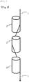
- the stabilized fiber bundle was passed through a roller group including three cylindrical rollers that were arranged between an oxidation oven and a precarbonization oven so that the center axes of the rollers might be on one straight line as shown in Fig. 1 .
- All the three rollers had a diameter of 10 mm, that is, R 1 , R 2 , and R 3 were all 10 mm.
- the three rollers were arranged so that both the distances L 1 and L 2 between the centers of the rollers might be 20 mm, that is, the gaps between the rollers might be 10 mm.
- the relational expression 0.75 ⁇ (R n + R n + 1 ) ⁇ L n ⁇ 2.0 ⁇ (R n + R n + 1 ) is established.
- the widths W 0 and W 2 of the stabilized fiber bundle were 3.0 ⁇ 10 -4 mm/dtex, that is, W 2 /W 0 was 1.0, and the spreading ratio W 1 /W 0 on the second roller was 1.4.
- the contact angles ⁇ 1 and ⁇ 3 of the stabilized fiber bundle with the first roller and the last roller, respectively, were 30°, and the contact angle ⁇ 2 of the stabilized fiber bundle with the second roller was 60°.
- the stabilized fiber bundle running on the rollers had a tension of 70 mg/dtex.
- the stabilized fiber bundle was precarbonized in a nitrogen atmosphere at 700°C, then carbonized at 1400°C, and then subjected to electrochemical treatment of fiber surface using sulfuric acid as an electrolytic solution, and a sizing agent containing a bisphenol A epoxy resin as a main component was added to the stabilized fiber bundle to give a carbon fiber bundle.
- the obtained carbon fiber bundle had a tensile strength of 430 kgf/mm 2 .
- Tables 1 and 2 The results are shown in Tables 1 and 2.
- a carbon fiber bundle was obtained in the same manner as in Example 1 except that an intermediate fiber bundle heat-treated at a stabilization temperature of 220 to 230°C and having a specific gravity of 1.20 was passed on rollers arranged between a folding roller and an oxidation oven, and then stabilized at 230 to 270°C to give a stabilized fiber bundle.
- the obtained carbon fiber bundle had a tensile strength of 450 kgf/mm 2 .
- Tables 1 and 2 The results are shown in Tables 1 and 2.
- a carbon fiber bundle was obtained in the same manner as in Example 1 except that an intermediate fiber bundle heat-treated at a stabilization temperature of 220 to 235°C and having a specific gravity of 1.25 was passed on rollers arranged between a folding roller and an oxidation oven, and then stabilized at 235 to 270°C to give a stabilized fiber bundle.
- the obtained carbon fiber bundle had a tensile strength of 460 kgf/mm 2 .
- Tables 1 and 2 The results are shown in Tables 1 and 2.
- a carbon fiber bundle was obtained in the same manner as in Example 1 except that the stabilized fiber bundle stabilized at a stabilization temperature of 230 to 280°C had a specific gravity of 1.50.
- the obtained carbon fiber bundle had a tensile strength of 440 kgf/mm 2 .
- the results are shown in Tables 1 and 2.
- a carbon fiber bundle was obtained in the same manner as in Example 1 except that a polyacrylonitrile precursor fiber having a single fiber fineness of 0.9 dtex and a number of filaments of 12,000 was obtained, and that the width W 0 of the fiber bundle was changed to 6.0 ⁇ 10 -4 mm/dtex.
- the obtained carbon fiber bundle had a tensile strength of 440 kgf/mm 2 .
- Tables 1 and 2 The results are shown in Tables 1 and 2.
- a carbon fiber bundle was obtained in the same manner as in Example 1 except that the roller diameter was 5 mm, both the distances L 1 and L 2 between the centers of the rollers were 15 mm, the contact angles ⁇ 1 and ⁇ 3 of the stabilized fiber bundle with the first roller and the last roller, respectively, were 15°, and the contact angle ⁇ 2 of the stabilized fiber bundle with the second roller was 30°.
- the relational expression 0.75 ⁇ (R n + R n + 1 ) ⁇ L n ⁇ 2.0 ⁇ (R n + R n + 1 ) is established.
- the obtained carbon fiber bundle had a tensile strength of 400 kgf/mm 2 .
- a carbon fiber bundle was obtained in the same manner as in Example 1 except that the roller diameter was 30 mm, both the distances L 1 and L 2 between the centers of the rollers were 45 mm, that is, the gaps between the rollers were 15 mm, the contact angles ⁇ 1 and ⁇ 3 of the stabilized fiber bundle with the first roller and the last roller, respectively, were 24°, and the contact angle ⁇ 2 of the stabilized fiber bundle with the second roller was 48°.
- the relational expression 0.75 ⁇ (R n + R n + 1 ) ⁇ L n ⁇ 2.0 ⁇ (R n + R n + 1 ) is established.
- the obtained carbon fiber bundle had a tensile strength of 430 kgf/mm 2 .
- a carbon fiber bundle was obtained in the same manner as in Example 1 except that the number of filaments of the polyacrylonitrile precursor fiber bundle was changed to 4,000, and that the width W 0 of the fiber bundle was changed to 2.0 ⁇ 10 -4 mm/dtex.
- the obtained carbon fiber bundle had a tensile strength of 420 kgf/mm 2 .
- a carbon fiber bundle was obtained in the same manner as in Example 1 except that the number of rollers was changed to thirteen.
- all the thirteen rollers had a diameter of 10 mm, and the rollers were arranged so that all the distances between the centers of the rollers might be 20 mm, that is, the gaps between the rollers might be 10 mm, and that all the center axes of the rollers might be on one straight line.
- the spreading ratio W 1 /W 0 was 1.4 on all the second to twelfth rollers.
- the obtained carbon fiber bundle had a tensile strength of 460 kgf/mm 2 . The results are shown in Tables 3 and 4.
- a carbon fiber bundle was obtained in the same manner as in Example 1 except that as shown in Fig. 3(1) , the second roller was displaced by 5 mm in the direction perpendicular to the running direction of the stabilized fiber bundle to adjust the contact angles ⁇ 1 and ⁇ 3 of the stabilized fiber bundle with the first roller and the third roller, respectively, to 15°, and to adjust the contact angle ⁇ 2 of the stabilized fiber bundle with the second roller to 30°.
- the distances L 1 and L 2 between the roller axes were 21 mm, but the relational expression 0.75 ⁇ (R n + R n + 1 ) ⁇ L n ⁇ 2.0 ⁇ (R n + R n + 1 ) is established.
- the obtained carbon fiber bundle had a tensile strength of 400 kgf/mm 2 .
- a carbon fiber bundle was obtained in the same manner as in Example 1 except that as shown in Fig. 3(2) , the second roller was displaced by 25 mm in the direction perpendicular to the running direction of the stabilized fiber bundle to adjust the contact angles ⁇ 1 and ⁇ 3 of the stabilized fiber bundle with the first roller and the third roller, respectively, to 70°, and to adjust the contact angle ⁇ 2 of the stabilized fiber bundle with the second roller to 140°.
- the distances L 1 and L 2 between the roller axes were 32 mm, but the relational expression 0.75 ⁇ (R n + R n + 1 ) ⁇ L n ⁇ 2.0 ⁇ (R n + R n + 1 ) is established.
- the obtained carbon fiber bundle had a tensile strength of 430 kgf/mm 2 .
- a carbon fiber bundle was obtained in the same manner as in Example 1 except that the tension of the stabilized fiber bundle was changed to 30 mg/dtex.
- the obtained carbon fiber bundle had a tensile strength of 400 kgf/mm 2 .
- the results are shown in Tables 3 and 4.
- a carbon fiber bundle was obtained in the same manner as in Example 1 except that the tension of the stabilized fiber bundle was changed to 180 mg/dtex.
- the obtained carbon fiber bundle had a tensile strength of 410 kgf/mm 2 .
- the results are shown in Tables 3 and 4.
- a carbon fiber bundle was obtained in the same manner as in Example 1 except that the three rollers arranged so that the center axes of the rollers might be on one straight line were absent. Since adhesion between the single yarns occurred in the stabilized fiber bundle, the tensile strength of the carbon fiber bundle was as low as 340 kgf/mm 2 . The results are shown in Tables 3 and 4.
- a stabilized fiber bundle was made to run in the same manner as in Example 1 except that the roller diameter was 3 mm, the contact angles ⁇ 1 and ⁇ 3 of the stabilized fiber bundle with the first roller and the last roller, respectively, were 11°, and the contact angle ⁇ 2 of the stabilized fiber bundle with the second roller was 22°. Since the roller diameter was small, the roller was bent and the fiber bundle could not be made to run, and no carbon fiber bundle was obtained.
- a carbon fiber bundle was obtained in the same manner as in Example 1 except that the roller diameter was 35 mm, the contact angles ⁇ 1 and ⁇ 3 of the stabilized fiber bundle with the first roller and the last roller, respectively, were 26°, and the contact angle ⁇ 2 of the stabilized fiber bundle with the second roller was 52°. Since the roller diameter was large and the effect of bending the stabilized fiber bundle running on the rollers was small, sufficient external force did not act on the stabilized fiber bundle. Therefore, the effect of suppressing the adhesion that is exerted by peeling of the single fibers that constitute the stabilized fiber bundle was insufficient, and the obtained carbon fiber bundle had a tensile strength of 370 kgf/mm 2 .
- a carbon fiber bundle was obtained in the same manner as in Example 1 except that an intermediate fiber bundle heat-treated at a stabilization temperature of 200 to 210°C and having a specific gravity of 1.17 was passed on rollers arranged between a folding roller and a stabilization heat treatment oven, and then stabilized at 210 to 270°C to give a stabilized fiber bundle. Due to the low stabilization temperature, the fiber bundle during the passage on the rollers was almost not stabilized. Since the single fibers that constitute the fiber bundle did not adhere to each other, the effect of suppressing the adhesion between the single fibers that is exerted by peeling between the single fibers during the passage on the rollers was not exhibited, and the obtained carbon fiber bundle had a tensile strength of 360 kgf/mm 2 . The results are shown in Tables 5 and 6.
- a carbon fiber bundle was obtained in the same manner as in Example 1 except that the stabilized fiber bundle stabilized at a stabilization temperature of 230 to 290°C had a specific gravity of 1.55.
- the adhesion between the single fibers that constitute the stabilized fiber bundle was strong, and not only the single fibers could not be peeled during passage of the stabilized fiber bundle on the rollers, but also fuzz occurred due to the brittleness of the stabilized fiber bundle, and the obtained carbon fiber bundle had a tensile strength of 370 kgf/mm 2 .
- the results are shown in Tables 5 and 6.
- a carbon fiber bundle was obtained in the same manner as in Example 1 except that the number of filaments of the polyacrylonitrile precursor fiber bundle was changed to 3,000, and that the width W 0 of the fiber bundle was changed to 1.5 ⁇ 10 -4 mm/dtex.
- the obtained carbon fiber bundle had a tensile strength of 360 kgf/mm 2 .
- the results are shown in Tables 5 and 6.
- a carbon fiber bundle was obtained in the same manner as in Example 1 except that a polyacrylonitrile precursor fiber having a single fiber fineness of 0.8 dtex and a number of filaments of 12,000 was obtained, and that the width W 0 of the fiber bundle was changed to 7.0 ⁇ 10 -4 mm/dtex. Since the width W 0 of the fiber bundle before coming into contact with the first roller was already large, spreading on the rollers did not occur, and the obtained carbon fiber bundle had a tensile strength of 370 kgf/mm 2 . The results are shown in Tables 5 and 6.
- a carbon fiber bundle was obtained in the same manner as in Example 1 except that as shown in Fig. 3(1) , the second roller was displaced by 7 mm in the direction perpendicular to the running direction of the stabilized fiber bundle to adjust both the distances L 1 and L 2 between the centers of the rollers to 21 mm, to adjust the contact angles ⁇ 1 and ⁇ 3 of the stabilized fiber bundle with the first roller and the third roller, respectively, to 10°, and to adjust the contact angle ⁇ 2 of the stabilized fiber bundle with the second roller to 20°.
- the contact angles with the rollers were small, the stabilized fiber bundle was hardly spread on the rollers, and the spreading ratio W 1 /W 0 was as low as 1.3.
- the adhesion between the single yarns that constitute the stabilized fiber bundle was not suppressed, and the obtained carbon fiber bundle had a tensile strength of 350 kgf/mm 2 .
- Tables 5 and 6 The results are shown in Tables 5 and 6.
- a carbon fiber bundle was obtained in the same manner as in Example 1 except that as shown in Fig. 3(2) , the second roller was displaced by 55 mm in the direction perpendicular to the running direction of the stabilized fiber bundle to adjust both the distances L 1 and L 2 between the centers of the rollers to 59 mm, to adjust the contact angles ⁇ 1 and ⁇ 3 of the stabilized fiber bundle with the first roller and the third roller, respectively, to 80°, and to adjust the contact angle ⁇ 2 of the stabilized fiber bundle with the second roller to 160°. Since fuzz occurred during passage on the rollers, the obtained carbon fiber bundle had a tensile strength of 340 kgf/mm 2 .
- a carbon fiber bundle was obtained in the same manner as in Example 1 except that as a result of adjusting the tension of the stabilized fiber bundle to 20 mg/dtex, the stabilized fiber bundle was hardly spread on the rollers due to the low tension, and the spreading ratio W 1 /W 0 was as low as 1.2.
- the adhesion between the single yarns that constitute the stabilized fiber bundle was not suppressed, and the obtained carbon fiber bundle had a tensile strength of 350 kgf/mm 2 .
- Tables 5 and 6 The results are shown in Tables 5 and 6.
Landscapes
- Engineering & Computer Science (AREA)
- Textile Engineering (AREA)
- Chemical & Material Sciences (AREA)
- Chemical Kinetics & Catalysis (AREA)
- General Chemical & Material Sciences (AREA)
- Mechanical Engineering (AREA)
- Physics & Mathematics (AREA)
- Thermal Sciences (AREA)
- Manufacturing & Machinery (AREA)
- Health & Medical Sciences (AREA)
- Toxicology (AREA)
- Inorganic Fibers (AREA)
Abstract
Description
- The present invention relates to a method for manufacturing a stabilized fiber bundle, the method being intended for obtaining a high-strength carbon fiber bundle by the suppression of adhesion between the single fibers in a stabilization process, and a method for manufacturing a carbon fiber bundle.
- Carbon fiber bundles have specific strength and specific modulus superior to those of other fibers, and are widely used as reinforcing materials for composite materials not only in sports and aerospace applications but also in general industrial applications such as automobiles, wind turbines, and pressure vessels. Particularly in the fields of aircraft and automobiles in which weight reduction of airframes and vehicle bodies is strongly demanded from the viewpoint of environment and cost, there is a high demand for carbon fiber bundles, and still higher performance of carbon fiber bundles has been demanded recently. In particular, carbon fiber bundles having high tensile strength have been demanded.
- The tensile strength of a carbon fiber bundle depends on the tensile strength of a polyacrylonitrile precursor that is a raw material of the carbon fiber bundle. It is known that factors that greatly affect the tensile strength of a carbon fiber bundle are flaws and toughness.
- Examples of the flaws include damages and voids that may occur in single fibers due to contact with and adhesion of foreign substances such as dust and metals, damages on the surface of single fibers due to adhesion between the single fibers, and damages of the carbon fiber bundle itself due to, for example, abrasion with rollers, all of which may occur in the manufacturing process of the carbon fiber bundle. Regardless of whether the flaws are formed inside or on the surface layer of the single fibers of the carbon fiber bundle, the carbon fiber bundle may be reduced in the tensile strength with an increase of the size and number of the flaws. In particular, when adhesion is formed between single fibers in the manufacturing process of the carbon fiber bundle, external force acts on the fiber bundle due to tension or the like to separate the adhered single fibers, and the surface layer of the single fibers of the carbon fiber bundle is torn in the direction of the fiber bundle to generate large flaws and greatly reduce the tensile strength.
- Further, examples of the factor of the toughness include a skin-core structural difference of the single fibers that constitute the stabilized fiber bundle due to a difference in heat treatment between the surface layer and the inner layer of the single fibers in the stabilization process. If there is a large difference in heat treatment between the surface layer and the inner layer, the stabilized fiber bundle may have reduced toughness, and the carbon fiber bundle tends to have reduced tensile strength.
- In general, a polyacrylonitrile carbon fiber bundle is manufactured by a method including heating a polyacrylonitrile precursor fiber bundle in an oxidizing gas atmosphere at 200 to 300°C to give a stabilized fiber bundle, and then heating the stabilized fiber bundle in an inert gas atmosphere at 1000°C or more. The polyacrylonitrile precursor fiber bundle usually includes 1,000 to 60,000 single fibers. Since the polyacrylonitrile precursor fiber bundle is combustible, in the stabilization process, the single fibers may adhere to each other during the stabilization of the polyacrylonitrile precursor fiber bundle in an oxidizing atmosphere.
- Several inventions have been made focusing on the adhesion between the single fibers during the manufacture of a carbon fiber bundle and the structural difference between the surface layer and the inner layer of the single fibers.
-
Patent Document 1 discloses that carbonaceous fibers fused together due to thermal alteration or the like of the fibers themselves are caused to run on a plurality of cylindrical rollers having center axes intersecting with each other to peel the carbonaceous fibers in a state of being displaced laterally on the rollers, whereby the carbonaceous fibers turn supple and the dispersibility of single yarns in a matrix resin is improved. -
Patent Document 2 discloses that during the convergence of pitch-based carbon fibers, the "fusion" in which a plurality of fibers are integrated with each other to cause a reduction of the tensile strength, or the "agglutination" in which a plurality of fibers are integrated with each other but can be easily separated into original fibers may occur, and the fiber bundle is spread after the precarbonization by being passed between ceramic rollers to prevent the reduction of the tensile strength due to convergence. -
Patent Document 3 discloses that in stabilizing a polyacrylonitrile precursor fiber bundle in an oxidizing atmosphere, the fiber bundle is passed on a grooved roller and then spread with a flat roller, that is, the flatness of the running fiber bundle is changed and then the fiber bundle is heat-treated, whereby the accumulation of reaction heat during the stabilization treatment is suppressed, and the structural difference between the surface layer and the inner layer of the single fibers due to a difference in the infusibilization reaction rate is reduced to improve the tensile strength of the carbon fiber. - Patent Document 4 discloses a method for manufacturing a high-strength carbon fiber, the method including passing a precursor fiber bundle on a plurality of solid guide bars to spread the precursor fiber bundle at the level of single fibers, and then stabilizing the spread precursor fiber bundle, thereby suppressing the adhesion between the single fibers.
- Patent Document 5 discloses a method for manufacturing a stabilized fiber bundle, the method including, in order to prevent the adhesion between the single fibers on a folding roller due to a high surface temperature of the folding roller during the stabilization treatment of a precursor fiber bundle, blowing the air at 15 to 30°C to the fiber bundle at a wind speed of 50 to 150 m/s before the precursor fiber bundle comes into contact with the roller to deform and cool the precursor fiber bundle.
- Patent Document 6 discloses a method for manufacturing a stabilized fiber bundle, the method including subjecting a fiber bundle during the stabilization treatment to the spreading treatment and then to the stabilization treatment again, in order to solve, during the stabilization treatment, the agglutination between the single fibers that may occur at the surface of the single fibers in the fiber bundle obtained by heat-treating an acrylonitrile fiber bundle by stabilization.
-
- Patent Document 1: Japanese Patent Laid-open Publication No.
61-138739 - Patent Document 2: Japanese Patent Laid-open Publication No.
5-287617 - Patent Document 3: Japanese Patent Laid-open Publication No.
2013-185285 - Patent Document 4: Japanese Patent Laid-open Publication No.
2001-131832 - Patent Document 5: Japanese Patent Laid-open Publication No.
2006-176909 - Patent Document 6: Japanese Patent Laid-open Publication No.
58-36216 - The inventions described in
Patent Documents - In the invention described in
Patent Document 3, the carbon fiber bundle has high tensile strength. The invention, however, has problems that the equipment cost is high due to the need for both the grooved roller and the flat roller before the carbon fiber bundle enters the stabilization treatment oven, and also that the workability at the time of threading is deteriorated. - In the invention described in Patent Document 4, the precursor fiber bundle is passed on a plurality of fixing bars and then subjected to the stabilization treatment. The invention has a problem that fuzz may occur due to abrasion between the fixing bars and the precursor fiber bundle so that both the tensile strength and process passability may be deteriorated.
- In the invention described in Patent Document 5, high-speed air of 50 to 150 m/s is blown to the fiber bundle before coming into contact with the folding roller used in the stabilization treatment. Therefore, the invention has a problem that fuzz inherent in the fiber bundle may occur so that both the tensile strength and process passability may be deteriorated.
- In the invention described in Patent Document 6, in order to solve the agglutination between the single yarns, the fiber bundle during the stabilization treatment is bent at an angle of 25 to 60° using a fixing bar, combined gears, or a crimper for bending the fiber bundle and is spread so that the agglutinated single yarns may be separated. Patent Document 6, however, does not describe to what extent the fiber bundle needs to be spread, that is, the spreading ratio of the fiber bundle, nor the roller diameter and the positional relationship between the rollers necessary for sufficient spreading. Moreover, what is described in the document as an effect of the invention is only the tensile strength of the stabilized fiber obtained by stabilizing the polyacrylonitrile precursor fiber and the fiber tensile strength of the fibrous activated carbon, and the document does not mention at all the tensile strength of a carbon fiber such as a polyacrylonitrile carbon fiber. Therefore, the effect of the invention for improving the tensile strength of the carbon fiber remains unclear.
- An object of the present invention is to solve the above-mentioned problems of the conventional techniques, and to provide a method for manufacturing a stabilized fiber bundle, the method being intended for obtaining a high-strength carbon fiber and including spreading, with external force, a fiber bundle during passage on a plurality of continuously arranged small-diameter rollers to bend the fiber bundle so that the adhesion between the single fibers that may occur during the stabilization treatment may be peeled, as well as a method for manufacturing a carbon fiber bundle.
- The method for manufacturing a stabilized fiber bundle of the present invention, the method being intended for solving the above-mentioned problems, is a method including the step of: stabilizing a polyacrylonitrile precursor fiber bundle in an oxidizing atmosphere at 200 to 300°C to manufacture a stabilized fiber bundle, wherein in the stabilizing step, a fiber bundle is made to run, with respect to a roller group including m pieces (where m is an integer of 3 or more) of rollers arranged continuously, to sequentially pass between an n-th roller and an (n + 1)-th roller (where n is an integer of 1 or more and (m - 1) or less), the m pieces of rollers arranged continuously have roller axes parallel to each other and perpendicular to a running direction of the fiber bundle, the rollers have a roller diameter of 5 to 30 mm, and the fiber bundle has a specific gravity of 1.20 to 1.50, and the method satisfies all of conditions (a) to (d) below:
- (a) Ln satisfies 0.75 × (Rn + Rn + 1) ≤ Ln ≤ 2.0 × (Rn + Rn + 1), wherein Rn [mm] is a roller diameter of an n-th roller, Rn + 1 [mm] is a roller diameter of an (n + 1)-th roller, and Ln [mm] is a distance between an n-th roller axis and an (n + 1)-th roller axis;
- (b) a width W0 of the fiber bundle before coming into contact with a first roller is in a range of 2.0 × 10⁻⁴ to 6.0 × 10⁻⁴ mm/dtex;
- (c) a width W2 of the fiber bundle after leaving an m-th roller satisfies 1.0 ≤ W2/W0 ≤ 1.1; and
- (d) a width W1 of the fiber bundle on second to (m - 1)-th rollers satisfies W1/W0 ≥ 1.4 in all the second to (m - 1)-th rollers.
- Further, the method for manufacturing a carbon fiber bundle of the present invention is a method including obtaining a stabilized fiber bundle by the above-mentioned method for manufacturing a stabilized fiber bundle, and carbonizing the stabilized fiber bundle in an inert atmosphere at 1000 to 2500°C.
- According to the method for manufacturing a stabilized fiber bundle and the method for manufacturing a carbon fiber bundle of the present invention, it is possible to suppress the adhesion between the single fibers that constitute the fiber bundle, which may occur during the stabilization treatment, and to manufacture a polyacrylonitrile carbon fiber bundle having high tensile strength.
-
-
Fig. 1 is a schematic configuration diagram showing an embodiment of a roller group according to the present invention. -
Fig. 2 is a top view of the roller group shown inFig. 1 . -
Fig. 3 is a schematic configuration diagram showing other embodiments of the roller group according to the present invention. - The polyacrylonitrile precursor fiber bundle used as a raw material of the carbon fiber bundle in the present invention can be obtained, for example, by spinning using, as an acrylic polymer, a homopolymer or a copolymer of acrylonitrile, and an organic or inorganic solvent. The acrylic polymer is a polymer containing 90 mass% or more of acrylonitrile, and may contain 10 mass% or less of other comonomers as necessary. Examples of the comonomers include acrylic acid, methacrylic acid, itaconic acid, and methyl esters, ethyl esters, propyl esters, butyl esters, alkali metal salts, and ammonium salts of these compounds, as well as allyl sulfonic acid, methallyl sulfonic acid, styrene sulfonic acid, and alkali metal salts of these compounds, but are not particularly limited.
- The method for manufacturing the polyacrylonitrile precursor fiber bundle used in the present invention is not particularly limited. Preferable examples of a method for spinning a fiber from a spinning dope include wet spinning in which a fiber is spun into a solvent in a coagulation bath, and dry-jet wet spinning in which a fiber is spun from a spinning dope once into the air. After the spinning, the spun yarn is subjected to steps such as drawing, washing with water, addition of an oil agent, drying and densification, and if necessary, post-drawing to provide a polyacrylonitrile precursor fiber bundle.
- The polyacrylonitrile precursor fiber bundle used in the present invention preferably has a single fiber fineness of 0.4 to 1.6 dtex. In addition, the polyacrylonitrile precursor fiber bundle preferably has a number of filaments, which is the total number of single fibers that constitute the polyacrylonitrile precursor fiber bundle, of 1,000 to 60,000, and the number of filaments is more preferably 1,000 to 36,000.
- In the method for manufacturing a stabilized fiber bundle of the present invention, the polyacrylonitrile precursor fiber bundle is stabilized in an oxidizing atmosphere at 200 to 300°C to manufacture a stabilized fiber bundle. The gas used as the oxidizing atmosphere is preferably the air in terms of cost. The oxidation oven is preferably a circulating hot air oven. It is preferable that the oxidation oven have, at both ends inside or outside thereof, folding rollers in multiple stages so that the fiber bundle can repeatedly run a plurality of times. The oxidation oven may be either a horizontal oxidation oven in which the fiber bundle runs in a horizontal direction, or a vertical oxidation oven in which the fiber bundle runs in a vertical direction. A horizontal oxidation oven is preferable because the oven facilitates handling of the fiber bundle in threading and yarn separating. The fiber bundle that has traversed through the oxidation oven is reversed in the running direction by the folding rollers and repeatedly passes through the oxidation oven so that the fiber bundle may be heated by the circulated hot air, whereby the polyacrylonitrile precursor fiber bundle is stabilized. In this process, in order for a carbon fiber bundle manufactured from the stabilized fiber bundle to easily exhibit sufficient tensile strength, it is preferable that the single fibers of the fiber bundle heat-treated in the stabilization heat treatment oven have a fineness of 0.4 to 1.7 dtex.
- The fiber bundle may have a form of either a non-twisted yarn having no twist or a twisted yarn having a number of twists in a certain direction, and is not particularly limited.
- In the method for manufacturing a stabilized fiber bundle of the present invention, when the polyacrylonitrile precursor fiber bundle is heat-treated in the stabilization process, adhesion between the single fibers that may occur in the heat treatment during the stabilization treatment is suppressed by the following matter: a fiber bundle is made to run, with respect to a roller group including m pieces (where m is an integer of 3 or more) of rollers arranged continuously, to sequentially pass between an n-th roller and an (n + 1)-th roller (where n is an integer of 1 or more and (m - 1) or less), the m pieces of rollers arranged continuously have roller axes parallel to each other and perpendicular to the running direction of the fiber bundle, the rollers have a roller diameter of 5 to 30 mm, and the fiber bundle has a specific gravity of 1.20 to 1.50.
- The fiber bundle that is made to run through the roller group may be either an intermediate fiber bundle that is in the middle of the stabilization treatment or a stabilized fiber bundle that has completed the stabilization treatment and passed through the oxidation oven.
- The fiber bundle has a specific gravity of 1.20 to 1.50, and the specific gravity is preferably 1.25 to 1.45. If the specific gravity is less than 1.20, the fiber bundle is hardly stabilized and the adhesion between the single fibers hardly occurs. Therefore, there is very little effect of improving the tensile strength of the carbon fiber bundle, which results from peeling between the single fibers that may occur during the passage through the roller group and the consequent suppression of adhesion. If the specific gravity exceeds 1.50, not only will the adhesion between the single fibers become so strong that the single fibers cannot be peeled, but also will the fiber bundle become brittle and cause fuzz during the passage through the roller group, so that the tensile strength may be reduced.
- The rollers making up the roller group are required to have a shape that has a circular cross section perpendicular to the running direction of the fiber bundle and that is capable of regulating the running position of the fiber bundle. Examples of the rollers having such a shape include a flat roller, a grooved roller, a heart roller, and a cylindrical roller. It is preferable to provide a roller group for each running fiber bundle so that the running position can be controlled for each fiber bundle.
- The rollers making up the roller group have a roller diameter, that is, a diameter of a roller of 5 to 30 mm, and the roller diameter is preferably 10 to 20 mm. If the roller diameter is less than 5 mm, since the roller has a thin shaft, the roller has low durability and cannot withstand long-term use. In addition, the contact between the roller and the fiber bundle is insufficient, resulting in lower peeling properties for peeling the adhered single fibers of the fiber bundle as well as little effect of suppressing the adhesion. Alternatively, if the roller diameter exceeds 30 mm, since the rollers have little effect of bending the fiber bundle running thereon, sufficient external force does not act on the fiber bundle, so that the suppression of adhesion exerted by peeling between the single fibers may become insufficient.
- In the method for manufacturing a stabilized fiber bundle of the present invention, the rollers are arranged continuously and the fiber bundle is made to run on the rollers sequentially, so that the single fibers that constitute the fiber bundle are continuously spread and the adhesion is suppressed. For that purpose, three or more rollers are required. Among the three or more rollers that are arranged continuously, the fiber bundle contacts the rollers present between the first roller and the last roller for the longest period and is spread. Therefore, one of the features of the present invention is that such rollers have the largest effect of peeling between the single yarns for suppressing the adhesion. Although there is no upper limit on the number of such rollers, twenty rollers are sufficient. This is because the effect of peeling the fiber bundle by running on the rollers is plateaued, and a large number of rollers may conversely cause a problem of fuzz of the fiber bundle.
- It is also necessary that the roller axes be parallel to each other for the running stability of the fiber bundle. If the roller axes are not parallel to each other, the fiber bundle may be displaced to the end of the rollers to fall off from the rollers, so that the running stability of the fiber bundle cannot be ensured. In addition, the present invention can be applied to both one fiber bundle and a plurality of fiber bundles running in parallel at the same time. It is also possible to arrange the rollers in a state where the centers of axes of the rollers making up the roller group are not on one straight line, but it is preferable that all the center axes of the rollers be parallel to the running direction of the fiber bundle and on one straight line as shown in
Fig. 1 . This is because it is preferable to reduce the installation space of the rollers, and that uniform application of the external force to the fiber bundle on the rollers makes the peeling of the single yarns uniform, so that the suppression of adhesion between the single yarns is better controlled, resulting in ease of obtaining the effect of improving the tensile strength of the carbon fiber bundle. - In order to make the fiber bundle run on the rollers and suppress the adhesion between the single yarns by the peeling at the time of spreading, it is necessary to apply appropriate external force to the fiber bundle running on the rollers. For that purpose, the positions of three or more continuously arranged rollers, in other words, the distance between the roller axes is important. The term "roller axis" as used herein refers to a straight line that is formed by extending the center point of a circular cross section of a roller, which is perpendicular to the running direction of the fiber bundle, in the length direction of the roller. The distance between the axes may be the same or different from each other between the rollers making up the roller group. Since m pieces of rollers are arranged continuously, m is an integer of 3 or more.
- Further, in the method for manufacturing a stabilized fiber bundle of the present invention, the condition (a) is satisfied: (a) Ln satisfies 0.75 × (Rn + Rn + 1) ≤ Ln ≤ 2.0 × (Rn + Rn + 1), wherein Rn [mm] is a roller diameter of an n-th roller, Rn + 1 [mm] is a roller diameter of an (n + 1)-th roller, and Ln [mm] is a distance between an n-th roller axis and an (n + 1)-th roller axis. That is, the diameter of the first roller arranged on the upstream side in the running direction of the fiber bundle is defined as R1 (mm), the diameter of the n-th roller is defined as Rn (mm), and the diameter of the last m-th roller is defined as Rm (mm). Further, it is important that Ln satisfy the relational expression 0.75 × (Rn + Rn + 1) ≤ Ln ≤ 2.0 × (Rn + Rn + 1), wherein Ln (mm) is the distance between an n-th roller axis and an (n + 1)-th roller axis in order to obtain the effect of suppressing the adhesion between the single yarns. If Ln is less than 0.75 × (Rn + Rn + 1), since the distance between the roller axes is shorter, when the fiber bundle runs with fuzz balls being attached thereto, the space between the rollers may be clogged with the fuzz balls and fuzz or yarn break may occur. Conversely, if Ln exceeds 2.0 × (Rn + Rn + 1), since the distance between the roller axes is longer, contact of the rollers with the fiber bundle is insufficient, and the effect of suppressing the adhesion between the single fibers is reduced. Moreover, since a large space is required to arrange the rollers making up the roller group, productivity of the equipment is deteriorated.
- The fiber bundle is spread on the rollers making up the roller group to apply external force to the fiber bundle. The width W0 of the fiber bundle before coming into contact with the first roller and the width W2 of the fiber bundle immediately after leaving the last m-th roller is preferably the same. This is because when a plurality of fiber bundles subjected to the stabilization treatment run at the same time, the width of the running fiber bundle that remains unchanged avoids the necessity for changing the width of the folding roller or the heat treatment oven. However, since the fiber bundle is spread on the plurality of rollers making up the roller group, the fiber bundle may run with the width W2 immediately after the passage on the last m-th roller being still wide. Therefore, in the method for manufacturing a stabilized fiber bundle of the present invention, it is necessary that the condition (c) be satisfied: (c) the width W2 of the fiber bundle after leaving the m-th roller satisfies 1.0 ≤ W2/W0 ≤ 1.1.
- In the method for manufacturing a stabilized fiber bundle of the present invention, the condition (b) is satisfied: (b) the width W0 of the fiber bundle before coming into contact with the first roller is in a range of 2.0 × 10⁻⁴ to 6.0 × 10⁻⁴ mm/dtex. The range is preferably 3.0 × 10⁻⁴ to 5.0 × 10⁻⁴ mm/dtex. If the width W0 of the fiber bundle is less than 2.0 × 10⁻⁴ mm/dtex, since the fiber bundle is thin, spreading of the fiber bundle on the rollers is insufficient, and the peeling necessary for suppressing the adhesion between the single yarns is insufficient. Moreover, since heat is accumulated in the fiber bundle during the stabilization treatment, fuzz or yarn break may easily occur, or fuzz may easily occur during running on the rollers. Conversely, if the width W0 of the fiber bundle exceeds 6.0 × 10⁻⁴ mm/dtex, since the fiber bundle is already wide, the fiber bundle is hardly spread on the rollers, and the effect of suppressing the adhesion between the single yarns is small.
- In addition, as for the fiber bundle on the second to (m - 1)-th rollers arranged between the first and last rollers, a largest effect of suppressing the adhesion, that is, effect of spreading the fiber bundle and peeling the adhered single fibers is exhibited. Therefore, in the method for manufacturing a stabilized fiber bundle of the present invention, the fiber bundle is spread so that the condition (d) is satisfied: the width W1 of the fiber bundle on second to (m - 1)-th rollers satisfies W1/W0 ≥ 1.4 in all the second to (m - 1)-th rollers. If the spreading ratio W1/W0 is less than 1.4 times, the fiber bundle is insufficiently spread and the adhered single fibers cannot be peeled, and the tensile strength of the carbon fiber bundle is not improved. There is no upper limit on the spreading ratio W1/W0 as long as the running stability of the fiber bundle on the rollers can be ensured, and a spreading ratio of at most 2.0 times can sufficiently exhibit the effect of the present invention.
- In order to further suppress the adhesion between the single fibers that may occur during the stabilization treatment, it is preferable to adjust the angle at which the fiber bundle running on a roller contacts the roller (hereinafter sometimes simply referred to as the "contact angle") as follows. That is, for the first roller and the last m-th roller, the contact angle of the fiber bundle with the roller is preferably 15 to 70°, more preferably 30 to 60°. Further, for the second to (m - 1)-th rollers that are arranged between the first roller and the last roller, the contact angle of the fiber bundle with the roller is preferably 30 to 140°, more preferably 60 to 120°. Herein, the "contact angle" means, as shown in
Fig. 2 , in a cross section perpendicular to the running direction of the fiber bundle, that is, in a circle in top view, the center angle of a sector formed by three points including the center of the roller, the point at which the fiber bundle starts to contact with the roller on the circumference of the roller, and the end point of contact at which the fiber bundle ceases to contact with the roller on the circumference of the roller. When the contact angle is within the above-mentioned range, the fiber bundle is sufficiently spread during running on the rollers, the external force is easily applied to the fiber bundle, and the single fibers that constitute the fiber bundle are peeled so that single fibers that may occur during the stabilization treatment can be easily suppressed. Moreover, it becomes easier to suppress the fuzz due to excessive contact with the rollers to maintain the grade of the fiber bundle. The contact angle can be adjusted by changing the roller diameter or the distance between the roller axes. - Further, as another factor for further suppressing the adhesion between the single fibers, it is preferable to adjust the tension of the fiber bundle during running on the rollers as follows. That is, in the method for manufacturing a stabilized fiber bundle of the present invention, the fiber bundle preferably has a tension of 30 to 180 mg/dtex, and the tension is more preferably 50 to 150 mg/dtex. When the tension of the fiber bundle is 30 to 180 mg/dtex, the fiber bundle is spread and external force is applied to the fiber bundle during running on the rollers, so that the single fibers that constitute the fiber bundle are subjected to a peeling action and the adhesion between the single fibers can be more easily suppressed. Moreover, it becomes easier to suppress the fuzz of the fiber bundle due to excessive tension to maintain the grade of the fiber bundle. Herein, the "tension" of the fiber bundle is an average of the tension before the fiber bundle comes into contact with the first roller and the tension after the fiber bundle leaves the last roller that are measured with a tension meter. The tension meter used may be a digital tension meter because of high accuracy.
- The place to arrange the rollers is preferably outside the oxidation oven where the fiber bundle is not stabilized. Specifically, since the purpose of arranging the rollers is to suppress the adhesion between the single yarns that may occur during the stabilization treatment, it is preferable to arrange the rollers at a place where the fiber bundle is not stabilized. In particular, it is more suitable that the ambient temperature around the place where the rollers are arranged be on the ordinary temperature level, since the fiber bundle running on the rollers will also have a temperature on the ordinary temperature level, and adhesion between the single yarns due to heat will be less likely to occur. More specifically, the rollers may be arranged at a place between the oxidation ovens or after the oxidation oven through which the stabilized fiber bundle runs to pass, or between the folding roller and the oxidation oven in the stabilization process.
- The method for manufacturing a carbon fiber bundle of the present invention includes the steps of obtaining a stabilized fiber bundle by the method for manufacturing a stabilized fiber bundle of the present invention, and carbonizing the stabilized fiber bundle in an inert atmosphere at 1000 to 2500°C. As a specific example of the above-mentioned method, for example, a stabilized fiber bundle obtained by the method for manufacturing a stabilized fiber bundle of the present invention described above is precarbonized in an inert atmosphere such as nitrogen at a temperature of 300 to 1000°C, and then carbonized in an inert atmosphere such as nitrogen at a temperature of 1000 to 2000°C to provide a carbonized fiber bundle. Moreover, it is possible to provide a graphitized fiber bundle having a higher elastic modulus by carbonizing the fiber bundle in an inert atmosphere such as nitrogen at a higher temperature of 2000 to 2500°C. In the present invention, the carbon fiber bundle may be either of the above-mentioned carbonized fiber bundle or graphitized fiber bundle.
- After the carbonization treatment, it is preferable to subject the carbon fiber bundle to oxidative surface treatment for the purpose of generating a functional group on the surface of the carbon fiber bundle to improve the adhesiveness with a matrix resin. Examples of the oxidative surface treatment method include liquid phase oxidation using a chemical solution, electrochemical treatment of fiber surface in which the carbon fiber bundle as an anode is treated in an electrolytic solution, and gas phase oxidative surface treatment by plasma treatment or the like in a phase state. The method of electrochemical treatment of fiber surface is preferable because the method is relatively good in handleability and is advantageous in terms of manufacturing cost. An electrolytic solution used in the case of the electrochemical treatment of fiber surface may be either an acidic aqueous solution or an alkaline aqueous solution. The acidic aqueous solution is preferably sulfuric acid or nitric acid having strong acidity. The alkaline aqueous solution is preferably an aqueous solution of an inorganic alkali such as ammonium carbonate, ammonium hydrogen carbonate, or ammonium bicarbonate.
- When the carbon fiber bundle is subjected to such electrochemical treatment of fiber surface, it is preferable to apply a sizing agent to the carbon fiber bundle after the carbon fiber bundle is subjected to a water washing step as necessary and then water is evaporated with a drier. The type of the sizing agent herein is not particularly limited, and the sizing agent may be appropriately selected from a bisphenol A epoxy resin containing an epoxy resin as a main component, a polyurethane resin and the like according to the matrix resin used in higher-order processing.
- Hereinafter, the present invention is described in detail by way of examples. In the examples of the present invention, cases where the number of rollers is three (n = 1 or 2, and m = 3) or thirteen (n is an integer of 1 to 12, and m = 13) are described, but the number of rollers is not limited to these. In each of the examples, Ln satisfies 0.75 × (Rn + Rn + 1) ≤ Ln ≤ 2.0 × (Rn + Rn + 1), wherein Rn is the roller diameter of the n-th roller, Rn + 1 is the roller diameter of the (n + 1)-th roller, and Ln is the distance between the n-th roller axis and the (n + 1)-th roller axis. The characteristics were evaluated according to the following methods.
- In the measurement of the widths W0, W1, and W2 of a fiber bundle, W0 is measured for the fiber bundle immediately before coming into contact with the first roller, W1 is measured for the fiber bundle running on a roller or rollers, and W2 is measured for the fiber bundle immediately after leaving the last roller. As for the reading accuracy, the widths of the fiber bundle were measured in the unit of mm to one decimal place, that is, to the unit of 0.1 mm. The widths of the fiber bundle were measured with the naked eye using a ruler. The ruler used was a first grade stainless steel metal straight ruler specified in JIS B7516(2005). The spreading ratios W2/W0 and W1/W0 were calculated from the obtained widths W0, W1, and W2 of the fiber bundle.
- The tension of a running fiber bundle was measured for the fiber bundle before coming into contact with the first roller and the fiber bundle after leaving the last roller. The tension meter used was a high-performance handheld digital tension meter manufactured by NIDEC-SHIMPO CORPORATION, and the tension was measured for 5 seconds. The average of the tension of the fiber bundle before coming into contact with the first roller and the tension of the fiber bundle after leaving the last roller was defined as the tension of the fiber bundle.
- The specific gravity of a fiber bundle was measured according to the method described in JIS R7601(2006). The specific gravity was measured using a fiber bundle before being made to run through a roller group. A reagent used was ethanol (a special grade reagent manufactured by Wako Pure Chemical Industries, Ltd.) without purification. A fiber bundle weighing 1.0 to 1.5 g was collected and absolutely dried at 120°C for 2 hours. The absolute dry mass (A) of the fiber bundle was measured, then the fiber bundle was impregnated with ethanol having a known specific gravity (specific gravity p), and the mass (B) of the fiber bundle in ethanol was measured. The specific gravity was calculated according to the following formula.

- The tensile strength of a carbon fiber bundle was determined according to "Carbon fiber - Determination of tensile properties of resin-impregnated yarn" of JIS R7608(2007) following the procedure described below. The resin formulation used was "Celloxide (registered trademark)" 2021P (manufactured by Daicel Chemical Industries, Ltd.)/boron trifluoride monoethylamine (manufactured by Tokyo Chemical Industry Co., Ltd.)/acetone = 100/3/4 (parts by mass). The curing conditions were a pressure of ordinary pressure, a temperature of 125°C, and a time of 30 minutes. Five carbon fiber bundles were measured, and the average thereof was taken as the tensile strength of the carbon fiber bundle.
- A spinning dope was prepared from an acrylic polymer, and then a polyacrylonitrile precursor fiber having a single fiber fineness of 1.1 dtex and a number of filaments of 12,000 was obtained by a wet spinning method. The polyacrylonitrile precursor fiber bundle was stabilized in an oxidizing atmosphere containing the air at 230 to 270°C, and after completion of the stabilization treatment, a stabilized fiber bundle having a specific gravity of 1.38 was obtained. The stabilized fiber bundle was passed through a roller group including three cylindrical rollers that were arranged between an oxidation oven and a precarbonization oven so that the center axes of the rollers might be on one straight line as shown in
Fig. 1 . All the three rollers had a diameter of 10 mm, that is, R1, R2, and R3 were all 10 mm. The three rollers were arranged so that both the distances L1 and L2 between the centers of the rollers might be 20 mm, that is, the gaps between the rollers might be 10 mm. In this case, for the distances L1 and L2 corresponding to Ln, the relational expression 0.75 × (Rn + Rn + 1) ≤ Ln ≤ 2.0 × (Rn + Rn + 1) is established. The widths W0 and W2 of the stabilized fiber bundle were 3.0 × 10⁻⁴ mm/dtex, that is, W2/W0 was 1.0, and the spreading ratio W1/W0 on the second roller was 1.4. The contact angles θ1 and θ3 of the stabilized fiber bundle with the first roller and the last roller, respectively, were 30°, and the contact angle θ2 of the stabilized fiber bundle with the second roller was 60°. The stabilized fiber bundle running on the rollers had a tension of 70 mg/dtex. - The stabilized fiber bundle was precarbonized in a nitrogen atmosphere at 700°C, then carbonized at 1400°C, and then subjected to electrochemical treatment of fiber surface using sulfuric acid as an electrolytic solution, and a sizing agent containing a bisphenol A epoxy resin as a main component was added to the stabilized fiber bundle to give a carbon fiber bundle. The obtained carbon fiber bundle had a tensile strength of 430 kgf/mm2. The results are shown in Tables 1 and 2.
- A carbon fiber bundle was obtained in the same manner as in Example 1 except that an intermediate fiber bundle heat-treated at a stabilization temperature of 220 to 230°C and having a specific gravity of 1.20 was passed on rollers arranged between a folding roller and an oxidation oven, and then stabilized at 230 to 270°C to give a stabilized fiber bundle. The obtained carbon fiber bundle had a tensile strength of 450 kgf/mm2. The results are shown in Tables 1 and 2.
- A carbon fiber bundle was obtained in the same manner as in Example 1 except that an intermediate fiber bundle heat-treated at a stabilization temperature of 220 to 235°C and having a specific gravity of 1.25 was passed on rollers arranged between a folding roller and an oxidation oven, and then stabilized at 235 to 270°C to give a stabilized fiber bundle. The obtained carbon fiber bundle had a tensile strength of 460 kgf/mm2. The results are shown in Tables 1 and 2.
- A carbon fiber bundle was obtained in the same manner as in Example 1 except that the stabilized fiber bundle stabilized at a stabilization temperature of 230 to 280°C had a specific gravity of 1.50. The obtained carbon fiber bundle had a tensile strength of 440 kgf/mm2. The results are shown in Tables 1 and 2.
- A carbon fiber bundle was obtained in the same manner as in Example 1 except that a polyacrylonitrile precursor fiber having a single fiber fineness of 0.9 dtex and a number of filaments of 12,000 was obtained, and that the width W0 of the fiber bundle was changed to 6.0 × 10⁻⁴ mm/dtex. The obtained carbon fiber bundle had a tensile strength of 440 kgf/mm2. The results are shown in Tables 1 and 2.
- A carbon fiber bundle was obtained in the same manner as in Example 1 except that the roller diameter was 5 mm, both the distances L1 and L2 between the centers of the rollers were 15 mm, the contact angles θ1 and θ3 of the stabilized fiber bundle with the first roller and the last roller, respectively, were 15°, and the contact angle θ2 of the stabilized fiber bundle with the second roller was 30°. In this case, for the distances L1 and L2 corresponding to Ln, the relational expression 0.75 × (Rn + Rn + 1) ≤ Ln ≤ 2.0 × (Rn + Rn + 1) is established. The obtained carbon fiber bundle had a tensile strength of 400 kgf/mm2. The results are shown in Tables 1 and 2.
- A carbon fiber bundle was obtained in the same manner as in Example 1 except that the roller diameter was 30 mm, both the distances L1 and L2 between the centers of the rollers were 45 mm, that is, the gaps between the rollers were 15 mm, the contact angles θ1 and θ3 of the stabilized fiber bundle with the first roller and the last roller, respectively, were 24°, and the contact angle θ2 of the stabilized fiber bundle with the second roller was 48°. In this case, for the distances L1 and L2 corresponding to Ln, the relational expression 0.75 × (Rn + Rn + 1) ≤ Ln ≤ 2.0 × (Rn + Rn + 1) is established. The obtained carbon fiber bundle had a tensile strength of 430 kgf/mm2. The results are shown in Tables 1 and 2.
- A carbon fiber bundle was obtained in the same manner as in Example 1 except that the number of filaments of the polyacrylonitrile precursor fiber bundle was changed to 4,000, and that the width W0 of the fiber bundle was changed to 2.0 × 10⁻⁴ mm/dtex. The obtained carbon fiber bundle had a tensile strength of 420 kgf/mm2. The results are shown in Tables 1 and 2.
- A carbon fiber bundle was obtained in the same manner as in Example 1 except that the number of rollers was changed to thirteen. In this case, all the thirteen rollers had a diameter of 10 mm, and the rollers were arranged so that all the distances between the centers of the rollers might be 20 mm, that is, the gaps between the rollers might be 10 mm, and that all the center axes of the rollers might be on one straight line. The spreading ratio W1/W0 was 1.4 on all the second to twelfth rollers. The obtained carbon fiber bundle had a tensile strength of 460 kgf/mm2. The results are shown in Tables 3 and 4.
- A carbon fiber bundle was obtained in the same manner as in Example 1 except that as shown in
Fig. 3(1) , the second roller was displaced by 5 mm in the direction perpendicular to the running direction of the stabilized fiber bundle to adjust the contact angles θ1 and θ3 of the stabilized fiber bundle with the first roller and the third roller, respectively, to 15°, and to adjust the contact angle θ2 of the stabilized fiber bundle with the second roller to 30°. In this case, the distances L1 and L2 between the roller axes were 21 mm, but the relational expression 0.75 × (Rn + Rn + 1) ≤ Ln ≤ 2.0 × (Rn + Rn + 1) is established. The obtained carbon fiber bundle had a tensile strength of 400 kgf/mm2. The results are shown in Tables 3 and 4. - A carbon fiber bundle was obtained in the same manner as in Example 1 except that as shown in
Fig. 3(2) , the second roller was displaced by 25 mm in the direction perpendicular to the running direction of the stabilized fiber bundle to adjust the contact angles θ1 and θ3 of the stabilized fiber bundle with the first roller and the third roller, respectively, to 70°, and to adjust the contact angle θ2 of the stabilized fiber bundle with the second roller to 140°. In this case, the distances L1 and L2 between the roller axes were 32 mm, but the relational expression 0.75 × (Rn + Rn + 1) ≤ Ln ≤ 2.0 × (Rn + Rn + 1) is established. The obtained carbon fiber bundle had a tensile strength of 430 kgf/mm2. The results are shown in Tables 3 and 4. - A carbon fiber bundle was obtained in the same manner as in Example 1 except that the tension of the stabilized fiber bundle was changed to 30 mg/dtex. The obtained carbon fiber bundle had a tensile strength of 400 kgf/mm2. The results are shown in Tables 3 and 4.
- A carbon fiber bundle was obtained in the same manner as in Example 1 except that the tension of the stabilized fiber bundle was changed to 180 mg/dtex. The obtained carbon fiber bundle had a tensile strength of 410 kgf/mm2. The results are shown in Tables 3 and 4.
- A carbon fiber bundle was obtained in the same manner as in Example 1 except that the three rollers arranged so that the center axes of the rollers might be on one straight line were absent. Since adhesion between the single yarns occurred in the stabilized fiber bundle, the tensile strength of the carbon fiber bundle was as low as 340 kgf/mm2. The results are shown in Tables 3 and 4.
- A stabilized fiber bundle was made to run in the same manner as in Example 1 except that the roller diameter was 3 mm, the contact angles θ1 and θ3 of the stabilized fiber bundle with the first roller and the last roller, respectively, were 11°, and the contact angle θ2 of the stabilized fiber bundle with the second roller was 22°. Since the roller diameter was small, the roller was bent and the fiber bundle could not be made to run, and no carbon fiber bundle was obtained. In this case, the distances L1 and L2 between the centers of the rollers were 13 mm, that is, the gaps between the rollers were 10 mm, and the relational expression 0.75 × (Rn + Rn + 1) ≤ Ln ≤ 2.0 × (Rn + Rn + 1) is not established. The results are shown in Tables 3 and 4.
- A carbon fiber bundle was obtained in the same manner as in Example 1 except that the roller diameter was 35 mm, the contact angles θ1 and θ3 of the stabilized fiber bundle with the first roller and the last roller, respectively, were 26°, and the contact angle θ2 of the stabilized fiber bundle with the second roller was 52°. Since the roller diameter was large and the effect of bending the stabilized fiber bundle running on the rollers was small, sufficient external force did not act on the stabilized fiber bundle. Therefore, the effect of suppressing the adhesion that is exerted by peeling of the single fibers that constitute the stabilized fiber bundle was insufficient, and the obtained carbon fiber bundle had a tensile strength of 370 kgf/mm2. In this case, the distances L1 and L2 between the centers of the rollers were 45 mm, that is, the gaps between the rollers were 10 mm, and the relational expression 0.75 × (Rn + Rn + 1) ≤ Ln ≤ 2.0 × (Rn + Rn + 1) is not established. The results are shown in Tables 3 and 4.
- A carbon fiber bundle was obtained in the same manner as in Example 1 except that an intermediate fiber bundle heat-treated at a stabilization temperature of 200 to 210°C and having a specific gravity of 1.17 was passed on rollers arranged between a folding roller and a stabilization heat treatment oven, and then stabilized at 210 to 270°C to give a stabilized fiber bundle. Due to the low stabilization temperature, the fiber bundle during the passage on the rollers was almost not stabilized. Since the single fibers that constitute the fiber bundle did not adhere to each other, the effect of suppressing the adhesion between the single fibers that is exerted by peeling between the single fibers during the passage on the rollers was not exhibited, and the obtained carbon fiber bundle had a tensile strength of 360 kgf/mm2. The results are shown in Tables 5 and 6.
- A carbon fiber bundle was obtained in the same manner as in Example 1 except that the stabilized fiber bundle stabilized at a stabilization temperature of 230 to 290°C had a specific gravity of 1.55. The adhesion between the single fibers that constitute the stabilized fiber bundle was strong, and not only the single fibers could not be peeled during passage of the stabilized fiber bundle on the rollers, but also fuzz occurred due to the brittleness of the stabilized fiber bundle, and the obtained carbon fiber bundle had a tensile strength of 370 kgf/mm2. The results are shown in Tables 5 and 6.
- A carbon fiber bundle was obtained in the same manner as in Example 1 except that the number of filaments of the polyacrylonitrile precursor fiber bundle was changed to 3,000, and that the width W0 of the fiber bundle was changed to 1.5 × 10⁻⁴ mm/dtex. The obtained carbon fiber bundle had a tensile strength of 360 kgf/mm2. The results are shown in Tables 5 and 6.
- A carbon fiber bundle was obtained in the same manner as in Example 1 except that a polyacrylonitrile precursor fiber having a single fiber fineness of 0.8 dtex and a number of filaments of 12,000 was obtained, and that the width W0 of the fiber bundle was changed to 7.0 × 10⁻⁴ mm/dtex. Since the width W0 of the fiber bundle before coming into contact with the first roller was already large, spreading on the rollers did not occur, and the obtained carbon fiber bundle had a tensile strength of 370 kgf/mm2. The results are shown in Tables 5 and 6.
- A carbon fiber bundle was obtained in the same manner as in Example 1 except that as shown in
Fig. 3(1) , the second roller was displaced by 7 mm in the direction perpendicular to the running direction of the stabilized fiber bundle to adjust both the distances L1 and L2 between the centers of the rollers to 21 mm, to adjust the contact angles θ1 and θ3 of the stabilized fiber bundle with the first roller and the third roller, respectively, to 10°, and to adjust the contact angle θ2 of the stabilized fiber bundle with the second roller to 20°. As a result, since the contact angles with the rollers were small, the stabilized fiber bundle was hardly spread on the rollers, and the spreading ratio W1/W0 was as low as 1.3. The adhesion between the single yarns that constitute the stabilized fiber bundle was not suppressed, and the obtained carbon fiber bundle had a tensile strength of 350 kgf/mm2. The results are shown in Tables 5 and 6. - A carbon fiber bundle was obtained in the same manner as in Example 1 except that as shown in
Fig. 3(2) , the second roller was displaced by 55 mm in the direction perpendicular to the running direction of the stabilized fiber bundle to adjust both the distances L1 and L2 between the centers of the rollers to 59 mm, to adjust the contact angles θ1 and θ3 of the stabilized fiber bundle with the first roller and the third roller, respectively, to 80°, and to adjust the contact angle θ2 of the stabilized fiber bundle with the second roller to 160°. Since fuzz occurred during passage on the rollers, the obtained carbon fiber bundle had a tensile strength of 340 kgf/mm2. In this case, for the distances L1 and L2 corresponding to Ln, the relational expression 0.75 × (Rn + Rn + 1) ≤ Ln ≤ 2.0 × (Rn + Rn + 1) is not established. The results are shown in Tables 5 and 6. - A carbon fiber bundle was obtained in the same manner as in Example 1 except that as a result of adjusting the tension of the stabilized fiber bundle to 20 mg/dtex, the stabilized fiber bundle was hardly spread on the rollers due to the low tension, and the spreading ratio W1/W0 was as low as 1.2. The adhesion between the single yarns that constitute the stabilized fiber bundle was not suppressed, and the obtained carbon fiber bundle had a tensile strength of 350 kgf/mm2. The results are shown in Tables 5 and 6.
[Table 1] Number of rollers Roller diameter [mm] Distance between roller axes [mm] Width of fiber bundle [mm/dtex] [pieces] R1 to R3 R4 to R13 L1 and L2 L3 to L12 W0 W2 Example 1 3 10 - 20 - 3.0 × 10⁻⁴ 3.0 × 10⁻⁴ Example 2 3 10 - 20 - 3.0 × 10⁻⁴ 3.0 × 10⁻⁴ Example 3 3 10 - 20 - 3.0 × 10⁻⁴ 3.0 × 10⁻⁴ Example 4 3 10 - 20 - 3.0 × 10⁻⁴ 3.0 × 10⁻⁴ Example 5 3 10 - 20 - 6.0 × 10⁻⁴ 3.0 × 10⁻⁴ Example 6 3 5 - 15 - 3.0 × 10⁻⁴ 3.0 × 10⁻⁴ Example 7 3 30 - 45 - 3.0 × 10⁻⁴ 3.0 × 10⁻⁴ Example 8 3 10 - 20 - 2.0 × 10⁻⁴ 3.0 × 10⁻⁴ [Table 2] Spreading ratio Specific gravity Contact angle [°] Tension Tensile strength of carbon fiber bundle W2/W0 W1/W0 First and last rollers Other rollers [mg/dtex] [kgf/mm2] Example 1 1.0 1.4 1.38 30 60 70 430 Example 2 1.0 1.4 1.20 30 60 70 450 Example 3 1.0 1.4 1.25 30 60 70 460 Example 4 1.0 1.4 1.50 30 60 70 440 Example 5 1.0 1.4 1.38 30 60 70 440 Example 6 1.0 1.4 1.38 15 30 70 400 Example 7 1.0 1.4 1.38 24 48 70 430 Example 8 1.0 1.4 1.38 30 60 70 420 [Table 3] Number of rollers Roller diameter [mm] Distance between roller axes [mm] Width of fiber bundle [mm/dtex] [pieces] R1 to R3 R4 to R13 L1 and L2 L3 to L12 W0 W2 Example 9 13 10 10 20 20 3.0 × 10⁻⁴ 3.0 × 10⁻⁴ Example 10 3 10 - 21 - 3.0 × 10⁻⁴ 3.0 × 10⁻⁴ Example 11 3 10 - 32 - 3.0 × 10⁻⁴ 3.0 × 10⁻⁴ Example 12 3 10 - 20 - 3.0 × 10⁻⁴ 3.0 × 10⁻⁴ Example 13 3 10 - 20 - 3.0 × 10⁻⁴ 3.0 × 10⁻⁴ Comparative Example 1 Without roller Comparative Example 2 3 3 - 13 - 3.0 × 10⁻⁴ 3.0 × 10⁻⁴ Comparative Example 3 3 35 - 45 - 3.0 × 10⁻⁴ 3.0 × 10⁻⁴ [Table 4] Spreading ratio Specific gravity Contact angle [°] Tension Tensile strength of carbon fiber bundle w2/w0 w1/w0 First and last rollers Other rollers [mg/dtex] [kgf/mm2] Example 9 1.0 1.4 1.38 30 60 70 460 Example 10 1.0 1.4 1.38 15 30 70 400 Example 11 1.0 1.4 1.38 70 140 70 430 Example 12 1.0 1.4 1.38 30 60 30 400 Example 13 1.0 1.4 1.38 30 60 180 410 Comparative Example 1 Without roller 1.38 Without roller 340 Comparative Example 2 1.0 1.4 1.38 11 22 70 - Comparative Example 3 1.0 1.4 1.38 26 52 70 370 [Table 5] Number of rollers Roller diameter [mm] Distance between roller axes [mm] Width of fiber bundle [mm/dtex] [pieces] R1 to R3 R4 to R13 L1 and L2 L3 to L12 W0 W2 Comparative Example 4 3 10 - 20 - 3.0 × 10⁻⁴ 3.0 × 10⁻⁴ Comparative Example 5 3 10 - 20 - 3.0 × 10⁻⁴ 3.0 × 10⁻⁴ Comparative Example 6 3 10 - 20 - 1.5 × 10⁻⁴ 3.0 × 10⁻⁴ Comparative Example 7 3 10 - 20 - 7.0 × 10⁻⁴ 3.0 × 10⁻⁴ Comparative Example 8 3 10 - 21 - 3.0 × 10⁻⁴ 3.0 × 10⁻⁴ Comparative Example 9 3 10 - 59 - 3.0 × 10⁻⁴ 3.0 × 10⁻⁴ Comparative Example 10 3 10 - 20 - 3.0 × 10⁻⁴ 3.0 × 10⁻⁴ [Table 6] Spreading ratio Specific gravity Contact angle [°] Tension Tensile strength of carbon fiber bundle W2/W0 W1/W0 First and last rollers Other rollers [mg/dtex] [kgf/mm2] Comparative Example 4 1.0 1.4 1.17 30 60 70 360 Comparative Example 5 1.0 1.4 1.55 30 60 70 370 Comparative Example 6 1.0 1.4 1.38 30 60 70 360 Comparative Example 7 1.0 1.4 1.38 30 60 70 370 Comparative Example 8 1.0 1.3 1.38 10 20 70 350 Comparative Example 9 1.0 1.4 1.38 80 160 70 340 Comparative Example 10 1.0 1.2 1.38 30 60 20 350 -
- 1: Intermediate fiber bundle or stabilized fiber bundle
- 2: Roller
- 3: Center of roller
- θ1, θ2, θ3: Contact angle
Claims (4)
- A method for manufacturing a stabilized fiber bundle, the method comprising the step of:stabilizing a polyacrylonitrile precursor fiber bundle in an oxidizing atmosphere at 200 to 300°C to manufacture a stabilized fiber bundle,wherein in the stabilizing step, a fiber bundle is made to run, with respect to a roller group including m pieces (where m is an integer of 3 or more) of rollers arranged continuously, to sequentially pass between an n-th roller and an (n + 1)-th roller (where n is an integer of 1 or more and (m - 1) or less),the m pieces of rollers arranged continuously have roller axes parallel to each other and perpendicular to a running direction of the fiber bundle,the rollers have a roller diameter of 5 to 30 mm, andthe fiber bundle has a specific gravity of 1.20 to 1.50, andthe method satisfies all of conditions (a) to (d) below:(a) Ln satisfies 0.75 × (Rn + Rn + 1) ≤ Ln ≤ 2.0 × (Rn + Rn + 1), wherein Rn [mm] is a roller diameter of an n-th roller, Rn + 1 [mm] is a roller diameter of an (n + 1)-th roller, and Ln [mm] is a distance between an n-th roller axis and an (n + 1)-th roller axis;(b) a width W0 of the fiber bundle before coming into contact with a first roller is in a range of 2.0 × 10⁻⁴ to 6.0 × 10⁻⁴ mm/dtex;(c) a width W2 of the fiber bundle after leaving an m-th roller satisfies 1.0 ≤ W2/W0 ≤ 1.1; and(d) a width W1 of the fiber bundle on second to (m - 1)-th rollers satisfies W1/W0 ≥ 1.4 in all the second to (m - 1)-th rollers.
- The method according to claim 1, wherein an angle at which the fiber bundle contacts a roller is 15 to 70° for the first and m-th rollers, and is 30 to 140° for the second to (m - 1)-th rollers.
- The method according to claim 1 or 2, wherein the fiber bundle has a tension of 30 to 180 mg/dtex.
- A method for manufacturing a carbon fiber bundle, the method comprising the steps of:obtaining a stabilized fiber bundle by the method according to any one of claims 1 to 3; andcarbonizing the stabilized fiber bundle in an inert atmosphere at 1000 to 2500°C.
Applications Claiming Priority (2)
| Application Number | Priority Date | Filing Date | Title |
|---|---|---|---|
| JP2018011166 | 2018-01-26 | ||
| PCT/JP2019/001228 WO2019146487A1 (en) | 2018-01-26 | 2019-01-17 | Flame-retardant fiber bundle and method for manufacturing carbon fiber bundle |
Publications (3)
| Publication Number | Publication Date |
|---|---|
| EP3744878A1 true EP3744878A1 (en) | 2020-12-02 |
| EP3744878A4 EP3744878A4 (en) | 2021-10-13 |
| EP3744878B1 EP3744878B1 (en) | 2025-01-22 |
Family
ID=67396026
Family Applications (1)
| Application Number | Title | Priority Date | Filing Date |
|---|---|---|---|
| EP19744501.8A Active EP3744878B1 (en) | 2018-01-26 | 2019-01-17 | Flame-retardant fiber bundle and method for manufacturing carbon fiber bundle |
Country Status (9)
| Country | Link |
|---|---|
| US (1) | US11319648B2 (en) |
| EP (1) | EP3744878B1 (en) |
| JP (1) | JP6547924B1 (en) |
| KR (1) | KR102586391B1 (en) |
| CN (1) | CN111601919B (en) |
| MX (1) | MX2020007377A (en) |
| RU (1) | RU2020122407A (en) |
| TW (1) | TW201934840A (en) |
| WO (1) | WO2019146487A1 (en) |
Families Citing this family (1)
| Publication number | Priority date | Publication date | Assignee | Title |
|---|---|---|---|---|
| CN114457462B (en) * | 2020-11-10 | 2023-08-08 | 中国石油化工股份有限公司 | Graphitization method for carbon fiber |
Family Cites Families (19)
| Publication number | Priority date | Publication date | Assignee | Title |
|---|---|---|---|---|
| JPS5352735A (en) * | 1976-10-25 | 1978-05-13 | Toho Rayon Co Ltd | Production of pre-oxidized fiber |
| JPS5836216A (en) | 1981-08-22 | 1983-03-03 | Toho Rayon Co Ltd | Production of bundle of preoxidized fiber |
| JPS61138739A (en) | 1984-12-11 | 1986-06-26 | 三菱化学株式会社 | Opening of carbonaceous fiber |
| JPS61289132A (en) * | 1985-06-14 | 1986-12-19 | Nikkiso Co Ltd | Production of flameproofing yarn for carbon fiber and flame proofing furnace |
| JPS6264310A (en) * | 1985-09-17 | 1987-03-23 | 角井 勲 | Hairbrush |
| JPH01118623A (en) * | 1987-10-28 | 1989-05-11 | Toray Ind Inc | Provision of precursor fiber with flame resistance |
| EP0426858B1 (en) * | 1989-02-23 | 1996-07-10 | Mitsubishi Rayon Co., Ltd. | Flameproofing apparatus |
| JPH05287617A (en) | 1992-04-08 | 1993-11-02 | Nippon Steel Corp | Production of pitch carbon fiber |
| JPH06264310A (en) * | 1993-03-08 | 1994-09-20 | Sumika Hercules Kk | Production of high-performance carbon fiber and/or graphite fiber |
| JP2001131832A (en) | 1999-11-01 | 2001-05-15 | Toray Ind Inc | Carbon fiber production method |
| JP2003055843A (en) * | 2001-06-04 | 2003-02-26 | Toray Ind Inc | Manufacturing method of carbon fiber |
| JP2004250817A (en) * | 2003-02-19 | 2004-09-09 | Toyota Industries Corp | Warp tension detecting device in loom |
| JP4360233B2 (en) * | 2004-03-11 | 2009-11-11 | 東レ株式会社 | Golf shaft |
| JP2006176909A (en) | 2004-12-22 | 2006-07-06 | Toho Tenax Co Ltd | Method for producing flame-resistant fiber |
| JP4844336B2 (en) * | 2006-10-11 | 2011-12-28 | 株式会社豊田自動織機 | Fiber bundle concentrator in spinning machine |
| JP2008115481A (en) * | 2006-11-01 | 2008-05-22 | Toray Ind Inc | Flame resistant furnace |
| KR101363675B1 (en) * | 2010-07-27 | 2014-02-14 | 미쯔비시 레이온 가부시끼가이샤 | Method for producing carbon-fiber bundles |
| JP5873358B2 (en) | 2012-03-09 | 2016-03-01 | 東邦テナックス株式会社 | Flame-resistant fiber strand, method for producing the same, and method for producing carbon fiber strand |
| JP6119168B2 (en) * | 2012-10-03 | 2017-04-26 | 三菱ケミカル株式会社 | Method for producing flame-resistant fiber bundle and method for producing carbon fiber bundle |
-
2019
- 2019-01-17 JP JP2019514846A patent/JP6547924B1/en active Active
- 2019-01-17 KR KR1020207017127A patent/KR102586391B1/en active Active
- 2019-01-17 WO PCT/JP2019/001228 patent/WO2019146487A1/en not_active Ceased
- 2019-01-17 MX MX2020007377A patent/MX2020007377A/en unknown
- 2019-01-17 CN CN201980008475.6A patent/CN111601919B/en active Active
- 2019-01-17 US US16/768,923 patent/US11319648B2/en active Active
- 2019-01-17 EP EP19744501.8A patent/EP3744878B1/en active Active
- 2019-01-17 RU RU2020122407A patent/RU2020122407A/en unknown
- 2019-01-23 TW TW108102459A patent/TW201934840A/en unknown
Also Published As
| Publication number | Publication date |
|---|---|
| EP3744878B1 (en) | 2025-01-22 |
| EP3744878A4 (en) | 2021-10-13 |
| CN111601919A (en) | 2020-08-28 |
| US20210222330A1 (en) | 2021-07-22 |
| CN111601919B (en) | 2022-06-28 |
| JPWO2019146487A1 (en) | 2020-02-06 |
| MX2020007377A (en) | 2020-09-07 |
| RU2020122407A (en) | 2022-02-28 |
| JP6547924B1 (en) | 2019-07-24 |
| TW201934840A (en) | 2019-09-01 |
| US11319648B2 (en) | 2022-05-03 |
| KR20200108416A (en) | 2020-09-18 |
| WO2019146487A1 (en) | 2019-08-01 |
| KR102586391B1 (en) | 2023-10-11 |
Similar Documents
| Publication | Publication Date | Title |
|---|---|---|
| EP3808880B1 (en) | Carbon fiber and method for producing same | |
| EP3425091B1 (en) | Bundle of carbon fibers | |
| EP3783136B1 (en) | Carbon fiber bundle, manufacturing method therefor, prepeg, and carbon-fiber-reinforced composite material | |
| JP6020201B2 (en) | Carbon fiber bundle and method for producing the same | |
| CN105408533B (en) | Carbon fiber bundle and the fibre bundle of resistance to burning | |
| US9109305B2 (en) | Preparation method for hollow carbon fiber | |
| EP2208813A1 (en) | Carbon fiber strand and process for producing the same | |
| KR102603178B1 (en) | Carbon fiber bundle and its manufacturing method | |
| EP2905364A1 (en) | Flame-proofed fiber bundle, carbon fiber bundle, and processes for producing these | |
| EP2840173A1 (en) | Carbon fiber bundle and method of producing carbon fiber bundle | |
| EP3705610A1 (en) | Carbon fiber bundle and method for producing same | |
| WO2017204026A1 (en) | Carbon fiber bundle and method for manufacturing same | |
| JP5811305B1 (en) | Carbon fiber and method for producing the same | |
| EP3744878B1 (en) | Flame-retardant fiber bundle and method for manufacturing carbon fiber bundle | |
| JP5873358B2 (en) | Flame-resistant fiber strand, method for producing the same, and method for producing carbon fiber strand | |
| JP2010071410A (en) | Grooved roller, and manufacturing device and manufacturing method of carbon fiber using the same | |
| EP4435159A1 (en) | Carbon fiber bundle and production method therefor | |
| EP4403680A1 (en) | Carbon fiber bundle and production method therefor | |
| JPH0737685B2 (en) | Carbon fiber with ultra high strength composite properties | |
| JP2006283225A (en) | Method for producing flame-proofed fiber and carbon fiber | |
| JP2025020078A (en) | Carbon fiber bundle and its manufacturing method | |
| JP2006152458A (en) | Method for producing flameproofed fiber | |
| JP2001131832A (en) | Carbon fiber production method |
Legal Events
| Date | Code | Title | Description |
|---|---|---|---|
| STAA | Information on the status of an ep patent application or granted ep patent |
Free format text: STATUS: THE INTERNATIONAL PUBLICATION HAS BEEN MADE |
|
| PUAI | Public reference made under article 153(3) epc to a published international application that has entered the european phase |
Free format text: ORIGINAL CODE: 0009012 |
|
| STAA | Information on the status of an ep patent application or granted ep patent |
Free format text: STATUS: REQUEST FOR EXAMINATION WAS MADE |
|
| 17P | Request for examination filed |
Effective date: 20200622 |
|
| AK | Designated contracting states |
Kind code of ref document: A1 Designated state(s): AL AT BE BG CH CY CZ DE DK EE ES FI FR GB GR HR HU IE IS IT LI LT LU LV MC MK MT NL NO PL PT RO RS SE SI SK SM TR |
|
| AX | Request for extension of the european patent |
Extension state: BA ME |
|
| DAV | Request for validation of the european patent (deleted) | ||
| DAX | Request for extension of the european patent (deleted) | ||
| A4 | Supplementary search report drawn up and despatched |
Effective date: 20210914 |
|
| RIC1 | Information provided on ipc code assigned before grant |
Ipc: B65H 57/14 20060101ALI20210908BHEP Ipc: D01F 9/32 20060101ALI20210908BHEP Ipc: D01F 6/18 20060101ALI20210908BHEP Ipc: D01D 10/02 20060101ALI20210908BHEP Ipc: D01F 9/22 20060101AFI20210908BHEP |
|
| GRAP | Despatch of communication of intention to grant a patent |
Free format text: ORIGINAL CODE: EPIDOSNIGR1 |
|
| STAA | Information on the status of an ep patent application or granted ep patent |
Free format text: STATUS: GRANT OF PATENT IS INTENDED |
|
| INTG | Intention to grant announced |
Effective date: 20241008 |
|
| GRAS | Grant fee paid |
Free format text: ORIGINAL CODE: EPIDOSNIGR3 |
|
| GRAA | (expected) grant |
Free format text: ORIGINAL CODE: 0009210 |
|
| STAA | Information on the status of an ep patent application or granted ep patent |
Free format text: STATUS: THE PATENT HAS BEEN GRANTED |
|
| P01 | Opt-out of the competence of the unified patent court (upc) registered |
Free format text: CASE NUMBER: APP_61658/2024 Effective date: 20241118 |
|
| AK | Designated contracting states |
Kind code of ref document: B1 Designated state(s): AL AT BE BG CH CY CZ DE DK EE ES FI FR GB GR HR HU IE IS IT LI LT LU LV MC MK MT NL NO PL PT RO RS SE SI SK SM TR |
|
| REG | Reference to a national code |
Ref country code: GB Ref legal event code: FG4D |
|
| REG | Reference to a national code |
Ref country code: CH Ref legal event code: EP |
|
| REG | Reference to a national code |
Ref country code: IE Ref legal event code: FG4D |
|
| REG | Reference to a national code |
Ref country code: DE Ref legal event code: R096 Ref document number: 602019065096 Country of ref document: DE |
|
| REG | Reference to a national code |
Ref country code: NL Ref legal event code: MP Effective date: 20250122 |
|
| PG25 | Lapsed in a contracting state [announced via postgrant information from national office to epo] |
Ref country code: NL Free format text: LAPSE BECAUSE OF FAILURE TO SUBMIT A TRANSLATION OF THE DESCRIPTION OR TO PAY THE FEE WITHIN THE PRESCRIBED TIME-LIMIT Effective date: 20250122 |
|
| PG25 | Lapsed in a contracting state [announced via postgrant information from national office to epo] |
Ref country code: RS Free format text: LAPSE BECAUSE OF FAILURE TO SUBMIT A TRANSLATION OF THE DESCRIPTION OR TO PAY THE FEE WITHIN THE PRESCRIBED TIME-LIMIT Effective date: 20250422 |
|
| PG25 | Lapsed in a contracting state [announced via postgrant information from national office to epo] |
Ref country code: FI Free format text: LAPSE BECAUSE OF FAILURE TO SUBMIT A TRANSLATION OF THE DESCRIPTION OR TO PAY THE FEE WITHIN THE PRESCRIBED TIME-LIMIT Effective date: 20250122 |
|
| PG25 | Lapsed in a contracting state [announced via postgrant information from national office to epo] |
Ref country code: PL Free format text: LAPSE BECAUSE OF FAILURE TO SUBMIT A TRANSLATION OF THE DESCRIPTION OR TO PAY THE FEE WITHIN THE PRESCRIBED TIME-LIMIT Effective date: 20250122 |
|
| PG25 | Lapsed in a contracting state [announced via postgrant information from national office to epo] |
Ref country code: ES Free format text: LAPSE BECAUSE OF FAILURE TO SUBMIT A TRANSLATION OF THE DESCRIPTION OR TO PAY THE FEE WITHIN THE PRESCRIBED TIME-LIMIT Effective date: 20250122 |
|
| REG | Reference to a national code |
Ref country code: LT Ref legal event code: MG9D |
|
| PG25 | Lapsed in a contracting state [announced via postgrant information from national office to epo] |
Ref country code: NO Free format text: LAPSE BECAUSE OF FAILURE TO SUBMIT A TRANSLATION OF THE DESCRIPTION OR TO PAY THE FEE WITHIN THE PRESCRIBED TIME-LIMIT Effective date: 20250422 Ref country code: IS Free format text: LAPSE BECAUSE OF FAILURE TO SUBMIT A TRANSLATION OF THE DESCRIPTION OR TO PAY THE FEE WITHIN THE PRESCRIBED TIME-LIMIT Effective date: 20250522 |
|
| REG | Reference to a national code |
Ref country code: AT Ref legal event code: MK05 Ref document number: 1761535 Country of ref document: AT Kind code of ref document: T Effective date: 20250122 |
|
| PG25 | Lapsed in a contracting state [announced via postgrant information from national office to epo] |
Ref country code: HR Free format text: LAPSE BECAUSE OF FAILURE TO SUBMIT A TRANSLATION OF THE DESCRIPTION OR TO PAY THE FEE WITHIN THE PRESCRIBED TIME-LIMIT Effective date: 20250122 |
|
| PG25 | Lapsed in a contracting state [announced via postgrant information from national office to epo] |
Ref country code: LV Free format text: LAPSE BECAUSE OF FAILURE TO SUBMIT A TRANSLATION OF THE DESCRIPTION OR TO PAY THE FEE WITHIN THE PRESCRIBED TIME-LIMIT Effective date: 20250122 Ref country code: PT Free format text: LAPSE BECAUSE OF FAILURE TO SUBMIT A TRANSLATION OF THE DESCRIPTION OR TO PAY THE FEE WITHIN THE PRESCRIBED TIME-LIMIT Effective date: 20250522 |
|
| PG25 | Lapsed in a contracting state [announced via postgrant information from national office to epo] |
Ref country code: BG Free format text: LAPSE BECAUSE OF FAILURE TO SUBMIT A TRANSLATION OF THE DESCRIPTION OR TO PAY THE FEE WITHIN THE PRESCRIBED TIME-LIMIT Effective date: 20250122 Ref country code: GR Free format text: LAPSE BECAUSE OF FAILURE TO SUBMIT A TRANSLATION OF THE DESCRIPTION OR TO PAY THE FEE WITHIN THE PRESCRIBED TIME-LIMIT Effective date: 20250423 |
|
| PG25 | Lapsed in a contracting state [announced via postgrant information from national office to epo] |
Ref country code: AT Free format text: LAPSE BECAUSE OF FAILURE TO SUBMIT A TRANSLATION OF THE DESCRIPTION OR TO PAY THE FEE WITHIN THE PRESCRIBED TIME-LIMIT Effective date: 20250122 |
|
| PG25 | Lapsed in a contracting state [announced via postgrant information from national office to epo] |
Ref country code: SE Free format text: LAPSE BECAUSE OF FAILURE TO SUBMIT A TRANSLATION OF THE DESCRIPTION OR TO PAY THE FEE WITHIN THE PRESCRIBED TIME-LIMIT Effective date: 20250122 |
|
| PG25 | Lapsed in a contracting state [announced via postgrant information from national office to epo] |
Ref country code: SM Free format text: LAPSE BECAUSE OF FAILURE TO SUBMIT A TRANSLATION OF THE DESCRIPTION OR TO PAY THE FEE WITHIN THE PRESCRIBED TIME-LIMIT Effective date: 20250122 |
|
| PG25 | Lapsed in a contracting state [announced via postgrant information from national office to epo] |
Ref country code: DK Free format text: LAPSE BECAUSE OF FAILURE TO SUBMIT A TRANSLATION OF THE DESCRIPTION OR TO PAY THE FEE WITHIN THE PRESCRIBED TIME-LIMIT Effective date: 20250122 |
|
| PG25 | Lapsed in a contracting state [announced via postgrant information from national office to epo] |
Ref country code: IT Free format text: LAPSE BECAUSE OF FAILURE TO SUBMIT A TRANSLATION OF THE DESCRIPTION OR TO PAY THE FEE WITHIN THE PRESCRIBED TIME-LIMIT Effective date: 20250122 |
|
| PG25 | Lapsed in a contracting state [announced via postgrant information from national office to epo] |
Ref country code: CZ Free format text: LAPSE BECAUSE OF FAILURE TO SUBMIT A TRANSLATION OF THE DESCRIPTION OR TO PAY THE FEE WITHIN THE PRESCRIBED TIME-LIMIT Effective date: 20250122 Ref country code: EE Free format text: LAPSE BECAUSE OF FAILURE TO SUBMIT A TRANSLATION OF THE DESCRIPTION OR TO PAY THE FEE WITHIN THE PRESCRIBED TIME-LIMIT Effective date: 20250122 |
|
| REG | Reference to a national code |
Ref country code: DE Ref legal event code: R097 Ref document number: 602019065096 Country of ref document: DE |
|
| PG25 | Lapsed in a contracting state [announced via postgrant information from national office to epo] |
Ref country code: RO Free format text: LAPSE BECAUSE OF FAILURE TO SUBMIT A TRANSLATION OF THE DESCRIPTION OR TO PAY THE FEE WITHIN THE PRESCRIBED TIME-LIMIT Effective date: 20250122 |
|
| PG25 | Lapsed in a contracting state [announced via postgrant information from national office to epo] |
Ref country code: SK Free format text: LAPSE BECAUSE OF FAILURE TO SUBMIT A TRANSLATION OF THE DESCRIPTION OR TO PAY THE FEE WITHIN THE PRESCRIBED TIME-LIMIT Effective date: 20250122 |
|
| PLBE | No opposition filed within time limit |
Free format text: ORIGINAL CODE: 0009261 |
|
| STAA | Information on the status of an ep patent application or granted ep patent |
Free format text: STATUS: NO OPPOSITION FILED WITHIN TIME LIMIT |
|
| 26N | No opposition filed |
Effective date: 20251023 |
|
| PGFP | Annual fee paid to national office [announced via postgrant information from national office to epo] |
Ref country code: FR Payment date: 20251128 Year of fee payment: 8 |
|
| PGFP | Annual fee paid to national office [announced via postgrant information from national office to epo] |
Ref country code: DE Payment date: 20251203 Year of fee payment: 8 |
|
| PG25 | Lapsed in a contracting state [announced via postgrant information from national office to epo] |
Ref country code: LT Free format text: LAPSE BECAUSE OF FAILURE TO SUBMIT A TRANSLATION OF THE DESCRIPTION OR TO PAY THE FEE WITHIN THE PRESCRIBED TIME-LIMIT Effective date: 20250122 |