EP3744642A1 - Method of assembling members of an assembly - Google Patents
Method of assembling members of an assembly Download PDFInfo
- Publication number
- EP3744642A1 EP3744642A1 EP20169545.9A EP20169545A EP3744642A1 EP 3744642 A1 EP3744642 A1 EP 3744642A1 EP 20169545 A EP20169545 A EP 20169545A EP 3744642 A1 EP3744642 A1 EP 3744642A1
- Authority
- EP
- European Patent Office
- Prior art keywords
- opening
- chamfer
- diameter
- drilling
- forming
- Prior art date
- Legal status (The legal status is an assumption and is not a legal conclusion. Google has not performed a legal analysis and makes no representation as to the accuracy of the status listed.)
- Granted
Links
Images


Classifications
-
- B—PERFORMING OPERATIONS; TRANSPORTING
- B23—MACHINE TOOLS; METAL-WORKING NOT OTHERWISE PROVIDED FOR
- B23B—TURNING; BORING
- B23B41/00—Boring or drilling machines or devices specially adapted for particular work; Accessories specially adapted therefor
-
- B—PERFORMING OPERATIONS; TRANSPORTING
- B23—MACHINE TOOLS; METAL-WORKING NOT OTHERWISE PROVIDED FOR
- B23B—TURNING; BORING
- B23B35/00—Methods for boring or drilling, or for working essentially requiring the use of boring or drilling machines; Use of auxiliary equipment in connection with such methods
-
- B—PERFORMING OPERATIONS; TRANSPORTING
- B23—MACHINE TOOLS; METAL-WORKING NOT OTHERWISE PROVIDED FOR
- B23B—TURNING; BORING
- B23B2215/00—Details of workpieces
- B23B2215/04—Aircraft components
-
- B—PERFORMING OPERATIONS; TRANSPORTING
- B23—MACHINE TOOLS; METAL-WORKING NOT OTHERWISE PROVIDED FOR
- B23B—TURNING; BORING
- B23B2220/00—Details of turning, boring or drilling processes
- B23B2220/04—Chamferring
-
- B—PERFORMING OPERATIONS; TRANSPORTING
- B64—AIRCRAFT; AVIATION; COSMONAUTICS
- B64F—GROUND OR AIRCRAFT-CARRIER-DECK INSTALLATIONS SPECIALLY ADAPTED FOR USE IN CONNECTION WITH AIRCRAFT; DESIGNING, MANUFACTURING, ASSEMBLING, CLEANING, MAINTAINING OR REPAIRING AIRCRAFT, NOT OTHERWISE PROVIDED FOR; HANDLING, TRANSPORTING, TESTING OR INSPECTING AIRCRAFT COMPONENTS, NOT OTHERWISE PROVIDED FOR
- B64F5/00—Designing, manufacturing, assembling, cleaning, maintaining or repairing aircraft, not otherwise provided for; Handling, transporting, testing or inspecting aircraft components, not otherwise provided for
- B64F5/10—Manufacturing or assembling aircraft, e.g. jigs therefor
-
- F—MECHANICAL ENGINEERING; LIGHTING; HEATING; WEAPONS; BLASTING
- F16—ENGINEERING ELEMENTS AND UNITS; GENERAL MEASURES FOR PRODUCING AND MAINTAINING EFFECTIVE FUNCTIONING OF MACHINES OR INSTALLATIONS; THERMAL INSULATION IN GENERAL
- F16B—DEVICES FOR FASTENING OR SECURING CONSTRUCTIONAL ELEMENTS OR MACHINE PARTS TOGETHER, e.g. NAILS, BOLTS, CIRCLIPS, CLAMPS, CLIPS OR WEDGES; JOINTS OR JOINTING
- F16B5/00—Joining sheets or plates, e.g. panels, to one another or to strips or bars parallel to them
- F16B5/02—Joining sheets or plates, e.g. panels, to one another or to strips or bars parallel to them by means of fastening members using screw-thread
-
- F—MECHANICAL ENGINEERING; LIGHTING; HEATING; WEAPONS; BLASTING
- F16—ENGINEERING ELEMENTS AND UNITS; GENERAL MEASURES FOR PRODUCING AND MAINTAINING EFFECTIVE FUNCTIONING OF MACHINES OR INSTALLATIONS; THERMAL INSULATION IN GENERAL
- F16B—DEVICES FOR FASTENING OR SECURING CONSTRUCTIONAL ELEMENTS OR MACHINE PARTS TOGETHER, e.g. NAILS, BOLTS, CIRCLIPS, CLAMPS, CLIPS OR WEDGES; JOINTS OR JOINTING
- F16B5/00—Joining sheets or plates, e.g. panels, to one another or to strips or bars parallel to them
- F16B5/04—Joining sheets or plates, e.g. panels, to one another or to strips or bars parallel to them by means of riveting
Definitions
- the following disclosure relates generally to assembly of aircraft structures, and, more particularly, a method of assembling aircraft.
- At least some known aircraft include rigid structure pylons that hold an engine in position under the aircraft's wing. Due to the weight of the engine, large fasteners are typically used to attach the pylon to the wing and to the engine nacelle, When attaching the pylon, it is important that the fastener openings are adequately aligned. In order to ensure alignment, in at least some known process, the structures to receive a fastener are assembled together and a single hole is drilled through the stack of assembled components.
- a method of assembling an aircraft assembly including a first member and a second member includes drilling at least one first opening through the first member, the at least one opening having a first diameter, and drilling at least one second opening through the second member, the at least one second opening having the first diameter.
- the method also includes forming a chamfer on the at least one first opening and the at least one second opening, the chamfer having a chamfer diameter, and positioning the first and second members to align the at least one first opening and the at least one second opening.
- the method further includes drilling the at least one first opening and the at least one second opening to a second diameter, wherein the second diameter is greater than the first diameter.
- a method of forming chamfered holes in assembled members includes drilling at least one opening through a first member of the assembled members, wherein the at least one opening is drilled at a first diameter.
- the method also includes forming a chamfer about the at least one opening, wherein the chamfer is formed at a chamfer diameter.
- the first member is then positioned in alignment with a mating second member, wherein the first member and the mating second member are to be assembled.
- the method further includes drilling the at least one opening in the first member and drilling the second member such that the at least one opening includes a second diameter greater than the first diameter.
- the implementations described herein relate to a method of assembling an assembly of members, and, more particularly, to methods of forming chamfers and aligning members of an assembly. More specifically, in some exemplary implementations, the method includes drilling a plurality of openings through each member of an assembly, where each opening includes a first diameter. A chamfer is then formed at both ends of each opening and the members are positioned to align their respective openings using determinate assembly features that align the members within a predetermined tolerance limit. The method further includes drilling through each of the aligned openings at a second diameter that is larger than the first diameter.
- the chamfers are formed at a diameter larger than the second diameter and the predetermined tolerance limit of the determinate assembly features is less than the difference between the chamfer diameter and the second diameter to ensure that the chamfers survive the second drilling step. Accordingly, the determinate assembly features facilitate aligning the chamfers of the assembly members such that any deviation in alignment is within the predetermined tolerance limit and is small enough to fall within the chamfer diameter.
- Forming the chamfers at the chamfer diameter on the openings prior to drilling the openings to the final, desired size at the second diameter allows for the second drilling step to occur within the chamfer and not at a sharp corner between the openings and a horizontal surface of the members.
- the chamfers "break" the corners of the openings to reduce or prevent the formation of burrs between the assembly members and therefore prevent the need to disassemble the first and second members after the final diameter is drilled to de-burr the openings. Elimination of the disassembly and de-burring steps significantly reduces manufacturing time and provides for costs savings.
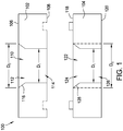
- FIG. 1 is a cross-sectional view of an assembly 100 including a first member 102 and a second member 104 at an initial drilling step of a method of assembling the assembly 100.
- assembly 100 is illustrated herein as having only first and second members 102 and 104, assembly 100 may include any number of members assembled together as described herein with respect to first and second members 102 and 104.
- first member 102 includes an exterior surface 106 and an opposing mating surface 108 configured to mate with second member 104.
- First member 102 also includes a first opening 110, having a first diameter D 1 , drilled through first member 102 and extending between exterior surface 106 and mating surface 108.
- first opening 110 includes a first end 112 proximate exterior surface 106 and a second end 114 proximate mating surface 108.
- first member 102 also includes a first chamfer 116, having a chamfer diameter D c , formed in exterior surface 106 at first end 112 of first opening 110.
- first chamfer 116 is formed simultaneously when first opening 110 is drilled. In other implementations, first chamfer 116 is formed after drilling first opening 110 through first member 102.
- second member 104 includes a mating surface 118 configured to mate with first member 102 and an opposing exterior surface 120.
- Second member 104 also includes a second opening 122, having a first diameter D 1 , drilled through second member 104 and extending between mating surface 118 and exterior surface 120.
- second opening 122 includes a first end 124 proximate mating surface 118 and a second end 126 proximate exterior surface 120.
- second member 104 also includes a first chamfer 128, having a chamfer diameter D c , formed in mating surface 118 at first end 124 of first opening 110.
- first chamfer 128 is formed simultaneously when second opening 122 is drilled. In other implementations, first chamfer 128 is formed after drilling second opening 122 through second member 104.
- FIG. 2 is a cross-sectional view of first member 102 and second member 104 illustrating a chamfering step of the method of assembly.
- first member 102 includes a second chamfer 130 formed in mating surface 108.
- Second chamfer 130 includes the same chamfer diameter D c as first chamfer 116.
- second chamfer 130 is formed at second end 114 of first opening 110 such that both first and second ends 112 and 114 each include a respective chamfer 116 and 130 at first opening 110.
- second member 104 includes a second chamfer 132 formed in exterior surface 120.
- Second chamfer 132 includes the same chamfer diameter D c as first chamfer 128.
- second chamfer 132 is formed at second end 126 of second opening 122 such that both ends 124 and 126 each include a respective chamfer 128 and 132 at second opening 122.
- FIG. 3 is a cross-sectional view of first member 102 and second member 104 illustrating a positioning step of the method of assembly.
- first member 102 and second member 104 each include a plurality of determinate assembly features 134 (shown in FIG. 2 ) integrally formed with first member 102 and second member 104.
- first member 102 includes a plurality of determinate assembly recesses 136 (shown in FIG. 2 )
- second member 104 includes a plurality of determinate assembly projections 138 (shown in FIG. 2 ).
- first member 102 includes determinate assembly projections 138 and second member 104 includes determinate assembly recesses 136.
- first and second members 102 and 104 each include both determinate assembly recesses 136 and determinate assembly projections 138 that correspond to the determinate assembly feature 134 on the opposing member.
- determinate assembly features 134 facilitate aligning first opening 110 of first member 102 with second opening 122 of second member 104 along a common centerline 140.
- determinate assembly features 134 are used to align first member 102 and second member 104 without using external tooling elements. More specifically, determinate assembly features 134 allow for first member 102 to be placed on second member 104 without using any external guides or frame that would then be removed from assembly 100. Additionally, determinate assembly features 134 facilitate positioning the first and second members 102 and 104 relative to each other within a predetermined tolerance limit, as described in further detail herein.
- FIG. 4 is a cross-sectional view of first member 102 and second member 104 illustrating a drilling step of the method of assembly.
- first chamfer 116 is drilled out to increase the common diameter of first opening 110 and second opening 122 to a second diameter D 2 .
- second diameter D 2 is greater than first diameter D 1 .
- chamfer diameter D c is greater than second diameter D 2 .
- FIG. 5 is a process flow diagram of a method 200 of assembling an assembly, such as assembly 100.
- Method 200 includes drilling 202 at least one first opening, such as first opening 110, through a first member, such as first member 102, such that the at least one first opening includes a first diameter, such as first diameter D 1 .
- Method 200 also includes drilling 204 at least one second opening, such as second opening 122, through a second member, such as second member 104 such that the at least one second opening also includes the first diameter.
- Method 200 further includes forming 206 a chamfer, such as first chamfers 116 and 128, on the at least one first opening 110 and the at least one second opening 122.
- Each chamfer is formed 206 with a chamfer diameter, such as chamfer diameter D c .
- forming 206 the chamfer includes forming a chamfer on both opposing ends of each of the at least one first opening and the at least one second opening.
- method 200 includes forming first chamfers 116 and 128 at first ends 112 and 124 of respective first and second openings 110 and 122.
- forming 206 a chamfer includes forming the chamfers at first ends of respective first and second openings simultaneously when drilling the at least one first opening and the at least one second opening at the first diameter. Additionally, forming 206 a chamfer includes forming 206 chamfers, such as second chamfers 130 and 132 at second ends, such as second ends 114 and 126 of respective first and second openings. For example, second chamfers 130 and 132 are formed after forming the first chamfers 116 and 128 at the first ends 112 and 124 of the at least one first opening 110 and the at least one second opening 122.
- Method 200 also includes positioning 208 the first and second members 102 and 104 to align the at least one first opening 110 and the at least one second opening 122.
- the positioning step 208 includes positioning the first and second members 102 and 104 relative to each other within a predetermined tolerance limit.
- each of the first and second members 102 and 104 includes a plurality of determinate assembly features 134 integrally formed therewith that align the first opening 110 with the second opening 122 along the centerline 140 without using external tooling elements.
- mating surfaces 108 and 118 are positioned 208 in contact with each other such that determinate assembly recesses 136 on first member 102 receive determinate assembly projections 138 on second member 104.
- determinate assembly features 134 allow for first member 102 to be positioned 208 on second member 104 without using any external guides or frame that would then need be removed from assembly 100.
- drilling 202 the at least one first opening and drilling 204 the at least one second opening at the first diameter D 1 is performed before the positioning step 208, and forming 206 the chamfers on the at least one first opening and the at least one second opening is performed before the positioning step 208.
- Method 200 further includes drilling 210 the at least one first opening 110 and the at least one second opening 122 to a second diameter, such as second diameter D 2 , that is greater than the first diameter.
- the second diameter is the final desired size of the first and second openings and will receive a fastener, such as fastener 142, therethrough.
- the determinate assembly features on the first and second members facilitate aligning the first and second openings within a predetermined tolerance limit to ensure the chamfers survive the second drilling step 210.
- the chamfers are formed at a chamfer diameter that is greater than the second diameter such that the chamfers are formed 206 for the final desired size of the first and second openings.
- the predetermined tolerance limit of the determinate assembly features is less than the difference between the chamfer diameter and the second diameter. As such, even at the predetermined tolerance limit of the determine assembly features, the first and second openings at the second diameter are contained with the chamfer diameters. Accordingly, at least a portion of the chamfers on the first and second members remain in place after drilling 210 the first and second openings to the second diameter.
- the method 200 also includes using a brush hone that has an associated diameter that is at least the second diameter, where the brush hone is used after drilling 201 too smooth the edges, such as edges 144, defined between the chamfers and the at least one first opening after drilling 210 the at least one first opening to the second diameter.
- the determinate assembly features facilitate aligning the chamfers of the first and second members such that any deviation in alignment is within the predetermined tolerance limit and is small enough to fall within the chamfer diameter.
- the chamfers are formed 206 when the first and second openings are at the first diameter such that the chamfers are already in place when the first and second openings are drilled 210 to the second diameter. Forming 206 the chamfers at the chamfer diameter on the openings prior to drilling 210 the openings to the final, desired size at the second diameter allows for the drilling step 210 to occur within the chamfer and not at a sharp corner between the opening and a horizontal surface of the members. The chamfers "break" the corners of the openings to reduce or prevent the formation of burrs between the first and second members and therefore prevent the need to disassemble the first and second members after the final diameter is drilled to de-burr the openings.
- method 200 also includes using a brush hone technique to smooth the edges, such as edges 144, defined between the chamfers and the at least one first opening after drilling 210 the at least one first opening to the second diameter. Similarly, method 200 also includes smoothing the edges defined between the chamfers and the at least one second opening after drilling 210 the at least one second opening to the second diameter. Additionally, method 200 includes installing a fastener, such as fastener 142, through the at least one first opening and the at least one second opening to secure the first member to the second member.
- the fastener is not limited to the type shown in FIG. 4 and may be any fastener type that facilitates operation of assembly 100 as described herein.
- FIG. 6 is a process flow diagram of a method 300 of forming chamfered holes in an assembly, such as assembly 100.
- Method 300 includes drilling 302 at least one opening, such as first opening 110, through a first member, such as first member 102, of the assembly such that the at least one opening includes a first diameter, such as first diameter D 1 .
- Method 300 also includes forming 304 a chamfer, such as first chamfers 116 and 128, about the at least one opening. Each chamfer is formed 304 with a chamfer diameter. Such as chamfer diameter D c .
- forming 304 the chamfer includes forming the chamfer on both opposing ends of the at least one opening.
- method 300 includes forming 304 the first chamfer 116 at first end 112 of the first opening 110 and forming 304 the second chamfer 130 at the second end 114 of the first opening 110.
- Method 200 also includes positioning 306 the first member in alignment with a mating second member, such as second member 104, that is to be assembled with the first member.
- Positioning 306 includes positioning 306 the first member and the mating second member relative to each other using a plurality of determinate assembly features, such as determinate assembly features 134, that are integrally formed on the first member and the mating second member.
- positioning 306 includes positioning 306 the first member and the mating second member relative to each other within a predetermined tolerance limit.
- the determinate assembly features facilitate positioning 306 the first member and the mating second member relative to each other within a predetermined tolerance limit.
- drilling 302 the at least one opening is performed before the positioning step 208, and forming 304 the chamfer on the at least one opening is performed before the positioning step 306.
- Method 300 further includes drilling 308 the at least one opening in the first member and drilling the mating second member such that the opening includes a second diameter D 2 that is greater than the first diameter D 1 .
- the at least one opening such as first opening 110
- drilling 302 the at least one opening includes drilling 302 the at least one opening at the first diameter that is within a range of between 50 percent and 90 percent of the second diameter.
- the second diameter is the final desired size of the first and second openings and will receive a fastener, such as fastener 142, therethrough.
- the determinate assembly features on the first and second members facilitate aligning the first and second openings within a predetermined tolerance limit to ensure the chamfers survive the second drilling step 308.
- the chamfers are formed at a chamfer diameter that is greater than the second diameter such that the chamfers are formed 304 for the final desired size of the first and second openings.
- the predetermined tolerance limit of the determinate assembly features is less than the difference between the chamfer diameter and the second diameter.
- the first and second openings at the second diameter are contained with the chamfer diameters. Accordingly, at least a portion of the chamfers on the first and second members remain in place after drilling 308 the first and second openings to the second diameter.
- the determinate assembly features facilitate aligning the chamfers of the first and second members such that any deviation in alignment is within the predetermined tolerance limit and is small enough to fall within the chamfer diameter.
- the chamfers are formed 304 when the first and second openings are at the first diameter such that the chamfers are already in place when the first and second openings are drilled 308 to the second diameter.
- Forming 304 the chamfers at the chamfer diameter on the openings prior to drilling 308 the openings to the final, desired size at the second diameter allows for the drilling step 308 to occur within the chamfer and not at a sharp corner between the opening and a horizontal surface of the members.
- the chamfers "break" the corners of the openings to reduce or prevent the formation of burrs between the first and second members and therefore prevent the need to disassemble the first and second members after the final diameter is drilled to de-burr the openings.
- method 300 also includes smoothing an edge, such as edge 144, defined between the chamfer and the at least one opening after drilling 210 the at least one opening to the second diameter. This step may be repeated at every edge between a chamfer and an opening.
- the implementations described herein relate to a method of assembling an assembly of members, and, more particularly, to methods of forming chamfers and aligning members of an assembly. More specifically, in some implementations, the method includes drilling a plurality of openings through each member of an assembly, where each opening includes a first diameter. A chamfer is then formed at both ends of each opening and the members are positioned to align their respective openings using determinate assembly features that align the members within a predetermined tolerance limit. The method further includes drilling through each of the aligned openings at a second diameter that is larger than the first diameter.
- the chamfers are formed at a diameter larger than the second diameter and the predetermined tolerance limit of the determinate assembly features is less than the difference between the chamfer diameter and the second diameter to ensure that the chamfers survive the second drilling step. Accordingly, the determinate assembly features facilitate aligning the chamfers of the assembly members such that any deviation in alignment is within the predetermined tolerance limit and is small enough to fall within the chamfer diameter.
- Forming the chamfers at the chamfer diameter on the openings prior to drilling the openings to the final, desired size at the second diameter allows for the second drilling step to occur within the chamfer and not at a sharp corner between the openings and a horizontal surface of the members.
- the chamfers "break" the corners of the openings to reduce or prevent the formation of burrs between the assembly members and therefore prevent the need to disassemble the first and second members after the final diameter is drilled to de-burr the openings. Elimination of the disassembly and de-burring steps significantly reduces manufacturing time and provides for costs savings.
Landscapes
- Engineering & Computer Science (AREA)
- Mechanical Engineering (AREA)
- Manufacturing & Machinery (AREA)
- Transportation (AREA)
- Aviation & Aerospace Engineering (AREA)
- Connection Of Plates (AREA)
- Drilling And Boring (AREA)
Abstract
Description
- The following disclosure relates generally to assembly of aircraft structures, and, more particularly, a method of assembling aircraft.
- At least some known aircraft include rigid structure pylons that hold an engine in position under the aircraft's wing. Due to the weight of the engine, large fasteners are typically used to attach the pylon to the wing and to the engine nacelle, When attaching the pylon, it is important that the fastener openings are adequately aligned. In order to ensure alignment, in at least some known process, the structures to receive a fastener are assembled together and a single hole is drilled through the stack of assembled components.
- However, as the drill exits each component in the stack, it may produce burrs between the adjacent components. The buildup of burrs between adjacent layers of the assembly stack up may cause stress points and may decrease the overall service life of the components. As such, at least some known assembly methods disassemble the stack of components after drilling in order to manually de-burr the drilled openings and form chamfers at each opening to facilitate fastener insertion. Disassembly and manual de-burring of the aircraft components results in relatively high manufacturing costs and long manufacturing time.
- A method of assembling an aircraft assembly including a first member and a second member is provided. The method includes drilling at least one first opening through the first member, the at least one opening having a first diameter, and drilling at least one second opening through the second member, the at least one second opening having the first diameter. The method also includes forming a chamfer on the at least one first opening and the at least one second opening, the chamfer having a chamfer diameter, and positioning the first and second members to align the at least one first opening and the at least one second opening. The method further includes drilling the at least one first opening and the at least one second opening to a second diameter, wherein the second diameter is greater than the first diameter.
- A method of forming chamfered holes in assembled members is provided. The method includes drilling at least one opening through a first member of the assembled members, wherein the at least one opening is drilled at a first diameter. The method also includes forming a chamfer about the at least one opening, wherein the chamfer is formed at a chamfer diameter. The first member is then positioned in alignment with a mating second member, wherein the first member and the mating second member are to be assembled. The method further includes drilling the at least one opening in the first member and drilling the second member such that the at least one opening includes a second diameter greater than the first diameter.
- The features, functions, and advantages that have been discussed can be achieved independently in various examples of the present disclosure or may be combined in yet other examples, further details of which can be seen with reference to the following description and drawings.
-
-
FIG. 1 is a cross-sectional view of a pair of structural components during an exemplary method of assembly illustrating an initial drilling step of the method; -
FIG. 2 is a cross-sectional view of the pair of structural components during the method of assembly illustrating a chamfering step of the method; -
FIG. 3 is a cross-sectional view of the pair of structural components during the method of assembly illustrating an aligning step of the method; -
FIG. 4 is a cross-sectional view of the pair of structural components during the method of assembly illustrating a subsequent drilling step of the method; -
FIG. 5 is a process flow diagram of a method of assembling an aircraft assembly; and -
FIG. 6 is a process flow diagram of a method of forming chamfered holes in assembled members. - Although specific features of various examples may be shown in some drawings and not in others, this is for convenience only. Any feature of any drawing may be referenced and/or claimed in combination with any feature of any other drawing.
- Unless otherwise indicated, the drawings provided herein are meant to illustrate features of examples of the disclosure. These features are believed to be applicable in a wide variety of systems comprising one or more examples of the disclosure. As such, the drawings are not meant to include all conventional features known by those of ordinary skill in the art to be required for the practice of the examples disclosed herein.
- The implementations described herein relate to a method of assembling an assembly of members, and, more particularly, to methods of forming chamfers and aligning members of an assembly. More specifically, in some exemplary implementations, the method includes drilling a plurality of openings through each member of an assembly, where each opening includes a first diameter. A chamfer is then formed at both ends of each opening and the members are positioned to align their respective openings using determinate assembly features that align the members within a predetermined tolerance limit. The method further includes drilling through each of the aligned openings at a second diameter that is larger than the first diameter. As described herein, the chamfers are formed at a diameter larger than the second diameter and the predetermined tolerance limit of the determinate assembly features is less than the difference between the chamfer diameter and the second diameter to ensure that the chamfers survive the second drilling step. Accordingly, the determinate assembly features facilitate aligning the chamfers of the assembly members such that any deviation in alignment is within the predetermined tolerance limit and is small enough to fall within the chamfer diameter.
- Forming the chamfers at the chamfer diameter on the openings prior to drilling the openings to the final, desired size at the second diameter allows for the second drilling step to occur within the chamfer and not at a sharp corner between the openings and a horizontal surface of the members. As such, the chamfers "break" the corners of the openings to reduce or prevent the formation of burrs between the assembly members and therefore prevent the need to disassemble the first and second members after the final diameter is drilled to de-burr the openings. Elimination of the disassembly and de-burring steps significantly reduces manufacturing time and provides for costs savings.
-
FIG. 1 is a cross-sectional view of anassembly 100 including afirst member 102 and asecond member 104 at an initial drilling step of a method of assembling theassembly 100. Althoughassembly 100 is illustrated herein as having only first andsecond members assembly 100 may include any number of members assembled together as described herein with respect to first andsecond members first member 102 includes anexterior surface 106 and anopposing mating surface 108 configured to mate withsecond member 104.First member 102 also includes afirst opening 110, having a first diameter D1, drilled throughfirst member 102 and extending betweenexterior surface 106 andmating surface 108. More specifically,first opening 110 includes afirst end 112 proximateexterior surface 106 and asecond end 114proximate mating surface 108. Furthermore,first member 102 also includes afirst chamfer 116, having a chamfer diameter Dc, formed inexterior surface 106 atfirst end 112 offirst opening 110. In some implementations,first chamfer 116 is formed simultaneously whenfirst opening 110 is drilled. In other implementations,first chamfer 116 is formed after drilling first opening 110 throughfirst member 102. - Similarly,
second member 104 includes amating surface 118 configured to mate withfirst member 102 and an opposingexterior surface 120.Second member 104 also includes asecond opening 122, having a first diameter D1, drilled throughsecond member 104 and extending betweenmating surface 118 andexterior surface 120. More specifically,second opening 122 includes afirst end 124proximate mating surface 118 and asecond end 126 proximateexterior surface 120. Furthermore,second member 104 also includes afirst chamfer 128, having a chamfer diameter Dc, formed inmating surface 118 atfirst end 124 offirst opening 110. In some implementations,first chamfer 128 is formed simultaneously whensecond opening 122 is drilled. In other implementations,first chamfer 128 is formed after drillingsecond opening 122 throughsecond member 104. -
FIG. 2 is a cross-sectional view offirst member 102 andsecond member 104 illustrating a chamfering step of the method of assembly. In some implementations including this implementation,first member 102 includes asecond chamfer 130 formed inmating surface 108.Second chamfer 130 includes the same chamfer diameter Dc asfirst chamfer 116. Specifically,second chamfer 130 is formed atsecond end 114 offirst opening 110 such that both first andsecond ends respective chamfer - Similarly,
second member 104 includes asecond chamfer 132 formed inexterior surface 120.Second chamfer 132 includes the same chamfer diameter Dc asfirst chamfer 128. Specifically,second chamfer 132 is formed atsecond end 126 ofsecond opening 122 such that both ends 124 and 126 each include arespective chamfer second opening 122. -
FIG. 3 is a cross-sectional view offirst member 102 andsecond member 104 illustrating a positioning step of the method of assembly. Specifically,first member 102 andsecond member 104 each include a plurality of determinate assembly features 134 (shown inFIG. 2 ) integrally formed withfirst member 102 andsecond member 104. More specifically, in some implementations,first member 102 includes a plurality of determinate assembly recesses 136 (shown inFIG. 2 ), andsecond member 104 includes a plurality of determinate assembly projections 138 (shown inFIG. 2 ). In other implementations,first member 102 includesdeterminate assembly projections 138 andsecond member 104 includes determinate assembly recesses 136. In yet other implementations, first andsecond members determinate assembly projections 138 that correspond to thedeterminate assembly feature 134 on the opposing member. - As shown in
FIG. 3 , mating surfaces 108 and 118 are positioned in contact with each other such that determinate assembly recesses 136 onfirst member 102 receivedeterminate assembly projections 138 onsecond member 104. In such a configuration, determinate assembly features 134 facilitate aligningfirst opening 110 offirst member 102 withsecond opening 122 ofsecond member 104 along acommon centerline 140. In some implementations including this implementation, determinate assembly features 134 are used to alignfirst member 102 andsecond member 104 without using external tooling elements. More specifically, determinate assembly features 134 allow forfirst member 102 to be placed onsecond member 104 without using any external guides or frame that would then be removed fromassembly 100. Additionally, determinate assembly features 134 facilitate positioning the first andsecond members -
FIG. 4 is a cross-sectional view offirst member 102 andsecond member 104 illustrating a drilling step of the method of assembly. Whenfirst member 102 andsecond member 104 have been assembled together such thatfirst opening 110 andsecond opening 122 are aligned,first chamfer 116 is drilled out to increase the common diameter offirst opening 110 andsecond opening 122 to a second diameter D2. In some implementations including this implementation, second diameter D2 is greater than first diameter D1. Furthermore, as shown inFIG. 4 , chamfer diameter Dc is greater than second diameter D2. -
FIG. 5 is a process flow diagram of amethod 200 of assembling an assembly, such asassembly 100.Method 200 includesdrilling 202 at least one first opening, such asfirst opening 110, through a first member, such asfirst member 102, such that the at least one first opening includes a first diameter, such as first diameter D1. Method 200 also includesdrilling 204 at least one second opening, such assecond opening 122, through a second member, such assecond member 104 such that the at least one second opening also includes the first diameter.Method 200 further includes forming 206 a chamfer, such asfirst chamfers first opening 110 and the at least onesecond opening 122. Each chamfer is formed 206 with a chamfer diameter, such as chamfer diameter Dc. In some implementations, forming 206 the chamfer includes forming a chamfer on both opposing ends of each of the at least one first opening and the at least one second opening. For example,method 200 includes formingfirst chamfers second openings - Furthermore, forming 206 a chamfer includes forming the chamfers at first ends of respective first and second openings simultaneously when drilling the at least one first opening and the at least one second opening at the first diameter. Additionally, forming 206 a chamfer includes forming 206 chamfers, such as
second chamfers second chamfers first chamfers first opening 110 and the at least onesecond opening 122. -
Method 200 also includes positioning 208 the first andsecond members first opening 110 and the at least onesecond opening 122. Thepositioning step 208 includes positioning the first andsecond members second members first opening 110 with thesecond opening 122 along thecenterline 140 without using external tooling elements. Specifically, mating surfaces 108 and 118 are positioned 208 in contact with each other such that determinate assembly recesses 136 onfirst member 102 receivedeterminate assembly projections 138 onsecond member 104. As such, determinate assembly features 134 allow forfirst member 102 to be positioned 208 onsecond member 104 without using any external guides or frame that would then need be removed fromassembly 100. - In some implementations including this implementation,
drilling 202 the at least one first opening anddrilling 204 the at least one second opening at the first diameter D1 is performed before thepositioning step 208, and forming 206 the chamfers on the at least one first opening and the at least one second opening is performed before thepositioning step 208. -
Method 200 further includesdrilling 210 the at least onefirst opening 110 and the at least onesecond opening 122 to a second diameter, such as second diameter D2, that is greater than the first diameter. In some implementations, the second diameter is the final desired size of the first and second openings and will receive a fastener, such asfastener 142, therethrough. The determinate assembly features on the first and second members facilitate aligning the first and second openings within a predetermined tolerance limit to ensure the chamfers survive thesecond drilling step 210. Specifically, the chamfers are formed at a chamfer diameter that is greater than the second diameter such that the chamfers are formed 206 for the final desired size of the first and second openings. Further, the predetermined tolerance limit of the determinate assembly features is less than the difference between the chamfer diameter and the second diameter. As such, even at the predetermined tolerance limit of the determine assembly features, the first and second openings at the second diameter are contained with the chamfer diameters. Accordingly, at least a portion of the chamfers on the first and second members remain in place after drilling 210 the first and second openings to the second diameter. Themethod 200 also includes using a brush hone that has an associated diameter that is at least the second diameter, where the brush hone is used after drilling 201 too smooth the edges, such asedges 144, defined between the chamfers and the at least one first opening after drilling 210 the at least one first opening to the second diameter. The determinate assembly features facilitate aligning the chamfers of the first and second members such that any deviation in alignment is within the predetermined tolerance limit and is small enough to fall within the chamfer diameter. - In some implementations including this implementation, the chamfers are formed 206 when the first and second openings are at the first diameter such that the chamfers are already in place when the first and second openings are drilled 210 to the second diameter. Forming 206 the chamfers at the chamfer diameter on the openings prior to
drilling 210 the openings to the final, desired size at the second diameter allows for thedrilling step 210 to occur within the chamfer and not at a sharp corner between the opening and a horizontal surface of the members. The chamfers "break" the corners of the openings to reduce or prevent the formation of burrs between the first and second members and therefore prevent the need to disassemble the first and second members after the final diameter is drilled to de-burr the openings. - In some implementations,
method 200 also includes using a brush hone technique to smooth the edges, such asedges 144, defined between the chamfers and the at least one first opening after drilling 210 the at least one first opening to the second diameter. Similarly,method 200 also includes smoothing the edges defined between the chamfers and the at least one second opening after drilling 210 the at least one second opening to the second diameter. Additionally,method 200 includes installing a fastener, such asfastener 142, through the at least one first opening and the at least one second opening to secure the first member to the second member. The fastener is not limited to the type shown inFIG. 4 and may be any fastener type that facilitates operation ofassembly 100 as described herein. -
FIG. 6 is a process flow diagram of amethod 300 of forming chamfered holes in an assembly, such asassembly 100.Method 300 includesdrilling 302 at least one opening, such asfirst opening 110, through a first member, such asfirst member 102, of the assembly such that the at least one opening includes a first diameter, such as first diameter D1. Method 300 also includes forming 304 a chamfer, such asfirst chamfers method 300 includes forming 304 thefirst chamfer 116 atfirst end 112 of thefirst opening 110 and forming 304 thesecond chamfer 130 at thesecond end 114 of thefirst opening 110. -
Method 200 also includes positioning 306 the first member in alignment with a mating second member, such assecond member 104, that is to be assembled with the first member. Positioning 306 includes positioning 306 the first member and the mating second member relative to each other using a plurality of determinate assembly features, such as determinate assembly features 134, that are integrally formed on the first member and the mating second member. Furthermore, positioning 306 includes positioning 306 the first member and the mating second member relative to each other within a predetermined tolerance limit. Specifically, the determinate assembly features facilitatepositioning 306 the first member and the mating second member relative to each other within a predetermined tolerance limit. - In some implementations including this implementation,
drilling 302 the at least one opening is performed before thepositioning step 208, and forming 304 the chamfer on the at least one opening is performed before thepositioning step 306. -
Method 300 further includesdrilling 308 the at least one opening in the first member and drilling the mating second member such that the opening includes a second diameter D2 that is greater than the first diameter D1. Specifically, the at least one opening, such asfirst opening 110, is drilled to the second diameter D2 during the same step as a second opening, such assecond opening 122, is drilled in the mating second member, such assecond member 104, at the second diameter D2. In some implementations, drilling 302 the at least one opening includesdrilling 302 the at least one opening at the first diameter that is within a range of between 50 percent and 90 percent of the second diameter. - As described herein, the second diameter is the final desired size of the first and second openings and will receive a fastener, such as
fastener 142, therethrough. The determinate assembly features on the first and second members facilitate aligning the first and second openings within a predetermined tolerance limit to ensure the chamfers survive thesecond drilling step 308. Specifically, the chamfers are formed at a chamfer diameter that is greater than the second diameter such that the chamfers are formed 304 for the final desired size of the first and second openings. Further, the predetermined tolerance limit of the determinate assembly features is less than the difference between the chamfer diameter and the second diameter. As such, even at the predetermined tolerance limit of the determine assembly features, the first and second openings at the second diameter are contained with the chamfer diameters. Accordingly, at least a portion of the chamfers on the first and second members remain in place after drilling 308 the first and second openings to the second diameter. The determinate assembly features facilitate aligning the chamfers of the first and second members such that any deviation in alignment is within the predetermined tolerance limit and is small enough to fall within the chamfer diameter. - In some implementations including this the implementation, the chamfers are formed 304 when the first and second openings are at the first diameter such that the chamfers are already in place when the first and second openings are drilled 308 to the second diameter. Forming 304 the chamfers at the chamfer diameter on the openings prior to
drilling 308 the openings to the final, desired size at the second diameter allows for thedrilling step 308 to occur within the chamfer and not at a sharp corner between the opening and a horizontal surface of the members. The chamfers "break" the corners of the openings to reduce or prevent the formation of burrs between the first and second members and therefore prevent the need to disassemble the first and second members after the final diameter is drilled to de-burr the openings. - In some implementations,
method 300 also includes smoothing an edge, such asedge 144, defined between the chamfer and the at least one opening after drilling 210 the at least one opening to the second diameter. This step may be repeated at every edge between a chamfer and an opening. - The implementations described herein relate to a method of assembling an assembly of members, and, more particularly, to methods of forming chamfers and aligning members of an assembly. More specifically, in some implementations, the method includes drilling a plurality of openings through each member of an assembly, where each opening includes a first diameter. A chamfer is then formed at both ends of each opening and the members are positioned to align their respective openings using determinate assembly features that align the members within a predetermined tolerance limit. The method further includes drilling through each of the aligned openings at a second diameter that is larger than the first diameter. As described herein, the chamfers are formed at a diameter larger than the second diameter and the predetermined tolerance limit of the determinate assembly features is less than the difference between the chamfer diameter and the second diameter to ensure that the chamfers survive the second drilling step. Accordingly, the determinate assembly features facilitate aligning the chamfers of the assembly members such that any deviation in alignment is within the predetermined tolerance limit and is small enough to fall within the chamfer diameter.
- Forming the chamfers at the chamfer diameter on the openings prior to drilling the openings to the final, desired size at the second diameter allows for the second drilling step to occur within the chamfer and not at a sharp corner between the openings and a horizontal surface of the members. As such, the chamfers "break" the corners of the openings to reduce or prevent the formation of burrs between the assembly members and therefore prevent the need to disassemble the first and second members after the final diameter is drilled to de-burr the openings. Elimination of the disassembly and de-burring steps significantly reduces manufacturing time and provides for costs savings.
- Further, the disclosure comprises examples according to the following clauses:
- Clause 1. A method (200) of assembling an aircraft assembly (100) including a first member (102) and a second member (104), the method comprising: drilling (202) at least one first opening (110) through the first member, the at least one first opening having a first diameter; drilling (204) at least one second opening (122) through the second member, the at least one second opening having the first diameter; forming (206) a chamfer (116, 128, 130, 132) on the at least one first opening and the at least one second opening, the chamfer having a chamfer diameter; positioning (208) the first and second members to align the at least one first opening and the at least one second opening; and drilling (210) the at least one first opening and the at least one second opening to a second diameter, wherein the second diameter is greater than the first diameter.
- Clause 2. The method (200) of clause 1, wherein forming (206) the chamfer (116, 128, 130, 132) comprises forming the chamfer on both opposing ends (112, 114, 124, 126) of each of the at least one first opening (110) and the at least one second opening (122).
- Clause 3. The method (200) of clause 2, wherein forming (206) the chamfer (116, 128) comprises forming the chamfer at a first end (112, 124) of each of the at least one first opening (110) and the at least one second opening (122) simultaneously when drilling (202, 204) the at least one first opening and the at least one second opening at the first diameter.
- Clause 4. The method (200) of clause 3, wherein forming (206) the chamfer (130, 132) comprises forming the chamfer at a second end (114, 126) of each of the at least one first opening (110) and the at least one second opening (122) after forming the chamfer (116, 128) at the first end (112, 124) of the at least one first opening and the at least one second opening.
- Clause 5. The method (200) of any of clauses 1 to 4, wherein the chamfer diameter is greater than the second diameter.
- Clause 6. The method (200) of any of clauses 1 to 5, wherein positioning (208) comprises positioning the first and second members (102, 104) using a plurality of determinate assembly features (134) integrally formed on the first and second members.
- Clause 7. The method (200) of clause 6, wherein positioning (208) comprises positioning the first and second members (102, 104) relative to each other within a predetermined tolerance limit, wherein the predetermined tolerance limit is less than a difference between the chamfer diameter and the second diameter.
- Clause 8. The method (200) of any of clauses 1 to 7, further comprising installing a fastener (142) through the at least one first opening (110) and the at least one second opening (122) to secure the first member (102) to the second member (104).
- Clause 9. The method (200) of any of clauses 1 to 8, wherein drilling (202) the at least one first opening (110) and drilling (204) the at least one second opening (122) at the first diameter is performed before the positioning (208) step, and wherein forming (206) the chamfer (116, 128, 130, 132) on the at least one first opening and the at least one second opening is performed before the positioning step.
- Clause 10. The method (200) of any of clauses 1 to 9, further comprising smoothing an edge (144) defined between the chamfer (116, 130) and the at least one first opening (110) after drilling (210) the at least one first opening at the second diameter.
- Clause 11. A method (300) of forming chamfered holes in an assembly (100), the method comprising: drilling (302) at least one opening (110) through a first member (102) of the assembly, wherein the at least one opening is drilled at a first diameter; forming (304) a chamfer (116) about the at least one opening, wherein the chamfer is formed at a chamfer diameter; positioning (306) the first member in alignment with a mating second member (104), wherein the first member and the mating second member are to be assembled; and drilling (308) the at least one opening in the first member and drilling the mating second member such that the at least one opening includes a second diameter greater than the first diameter.
- Clause 12. The method (300) of clause 11, wherein the chamfer diameter is greater than the second diameter.
- Clause 13. The method (300) of clause 11 or 12, wherein positioning (306) comprises positioning the first member (102) and the mating second member (104) using a plurality of determinate assembly features (134) integrally formed on the first member and the mating second member.
- Clause 14. The method (300) of clause 13, wherein positioning (306) comprises positioning the first member (102) and the mating second member (104) relative to each other within a predetermined tolerance limit.
- Clause 15. The method (300) of clause 14, wherein the predetermined tolerance limit is less than a difference between the chamfer diameter and the second diameter.
- Clause 16. The method (300) of any of clauses 11 to 15, wherein drilling (302) the at least one opening (110) comprises drilling the at least one opening at the first diameter that is within a range of between 50 percent and 90 percent of the second diameter.
- Clause 17. The method (300) of any of clauses 11 to 16, wherein drilling (302) the at least one opening (110) at the first diameter is performed before the positioning step (306), and wherein forming (304) the chamfer (116) on the at least one opening is performed before the positioning step.
- Clause 18. The method (300) of any of clauses 11 to 17, wherein forming (304) the chamfer (116) comprises forming the chamfer on both opposing ends (112, 114) of the at least one opening (110).
- Clause 19. The method (300) of any of clauses 11 to 18, further comprising smoothing an edge (144) defined between the chamfer (116) and the at least one opening (110) after drilling (308) the at least one opening at the second diameter.
- This written description uses examples to disclose various implementations, and also to enable any person skilled in the art to practice the various implementations, including making and using any devices or systems and performing any incorporated methods. The patentable scope of the disclosure is defined by the claims, and may include other examples that occur to those skilled in the art.
Claims (15)
- A method (200) of assembling an aircraft assembly (100) including a first member (102) and a second member (104), the method comprising:drilling (202) a first opening (110) through the first member (102), the first opening (110) having a first diameter;drilling (204) a second opening (122) through the second member (104), the second opening (122) having the first diameter;forming (206) a first chamfer (116) on the first opening (110) and forming a first chamfer (128) on the second opening (122), the first chamfer (116) on the first opening (110) and the first chamfer (128) on the second opening (122) having a chamfer diameter;positioning (208) the first member (102) and the second member (104) to align the first opening (110) and the second opening (122); anddrilling (210) the first opening (110) and the second opening (122) to a second diameter, wherein the second diameter is greater than the first diameter.
- The method (200) of claim 1, wherein the chamfer diameter is greater than the second diameter.
- The method of claim 1 or 2, wherein positioning (208) the first member (102) and second member (104) to align the first opening (110) and the second opening (122) comprises positioning the first member (102) and the second member (104) such that a first mating surface (108) of the first member (102) abuts a second mating surface (118) of the second member (104).
- The method of claim 3, wherein positioning (208) the first member (102) and the second member (104) to align the first opening (110) and the second opening (122) comprises positioning the first member (102) and the second member (104) such that the second mating surface (118) includes the first chamfer (128) on the second opening (122).
- The method (200) of any of claims 1 to 4, further comprising forming a second chamfer (130) on an opposing end (114) of the first opening (110) and forming a second chamfer (132) on an opposing end (126) of the second opening (122), the second chamfer (130) on the first opening (110) and the second chamfer (132) on the second opening (122) having the chamfer diameter.
- The method (200) of claim 5, wherein forming (206) the first chamfer (116) on the first opening (110) comprises forming the first chamfer (116) at a first end (112) of the first opening (110) simultaneously with drilling (202) the first opening (110) at the first diameter and forming (206) the first chamfer (128) on the second opening (122) comprises forming the first chamfer (128) at a first end (124) of the second opening (122) simultaneously with drilling (204) the second opening (122) at the first diameter.
- The method (200) of claim 6, wherein forming (206) the second chamfer (130) on the first opening (110) comprises forming the second chamfer (130) at a second end (114) of the first opening (110) after forming the first chamfer (116) at the first end (112) of the first opening (110), and forming (206) the second chamfer (132) on the second opening (122) comprises forming the second chamfer (132) at a second end (126) of the second opening (122) after forming the first chamfer (128) at the first end (124) of the second opening (122).
- The method (200) of any of claims 1 to 7, wherein positioning (208) the first member (102) and the second member (104) comprises positioning the first member (102) and the second member (104) using a plurality of determinate assembly features (134) integrally formed on the first member (102) and the second member (104).
- The method (200) of claim 8, wherein positioning (208) the first member (102) and the second member (104) comprises positioning the first member (102) and the second member (104) relative to each other within a predetermined tolerance limit.
- The method (200) of claim 9, wherein the predetermined tolerance limit is less than a difference between the chamfer diameter and the second diameter.
- The method (200) of any of claims 1 to 10, further comprising installing a fastener (142) through the first opening (110) and the second opening (122) to secure the first member (102) to the second member (104).
- The method (200) of any of claims 1 to 11, wherein drilling (202) the first opening (110) and drilling (204) the second opening (122) at the first diameter is performed before positioning (208) the first member (102) and the second member (104), and wherein forming (206) the first chamfer (116) on the first opening (110) and the second chamfer (128) on the second opening (112) are performed before positioning (208) the first member (102) and the second member (104).
- The method (200) of any of claims 1 to 12, further comprising smoothing an edge (144) defined between the first chamfer (116) on the first opening (110) and the first opening (110) after drilling (210) the first opening (110) at the second diameter.
- The method (300) of any of claims 1 to 13, wherein drilling (302) the first opening (110) and the second opening (122) comprises drilling the first opening (110) and the second opening (122) at the first diameter that is within a range of between 50 percent and 90 percent of the second diameter.
- The method (300) of any of claims 1 to 14, wherein the first member (102) is an aircraft wing structure and the second member (104) is an engine pylon.
Applications Claiming Priority (1)
| Application Number | Priority Date | Filing Date | Title |
|---|---|---|---|
| US16/423,610 US11213897B2 (en) | 2019-05-28 | 2019-05-28 | Method of assembling members of an assembly |
Publications (2)
| Publication Number | Publication Date |
|---|---|
| EP3744642A1 true EP3744642A1 (en) | 2020-12-02 |
| EP3744642B1 EP3744642B1 (en) | 2022-12-14 |
Family
ID=70483014
Family Applications (1)
| Application Number | Title | Priority Date | Filing Date |
|---|---|---|---|
| EP20169545.9A Active EP3744642B1 (en) | 2019-05-28 | 2020-04-15 | Method of assembling members of an assembly |
Country Status (3)
| Country | Link |
|---|---|
| US (1) | US11213897B2 (en) |
| EP (1) | EP3744642B1 (en) |
| AU (1) | AU2020202051B2 (en) |
Citations (5)
| Publication number | Priority date | Publication date | Assignee | Title |
|---|---|---|---|---|
| US4984347A (en) * | 1989-05-05 | 1991-01-15 | Mcdonnell Douglas Corporation | Method for attaching a doubler to a skin structure |
| JP2000288813A (en) * | 1999-03-31 | 2000-10-17 | Suzuki Kogyo Kk | Double chamfering drill |
| JP2010247281A (en) * | 2009-04-16 | 2010-11-04 | Shinmaywa Industries Ltd | Method of perforating fiber reinforced resin composite laminate and method of assembling fiber reinforced resin composite laminate having through holes formed using the perforation method and assembly member |
| DE102011122539A1 (en) * | 2011-12-27 | 2013-06-27 | Rolls-Royce Deutschland Ltd & Co Kg | Method for producing a bore in a workpiece |
| EP3208017A1 (en) * | 2016-02-17 | 2017-08-23 | The Boeing Company | Methods of forming holes in a workpiece and associated systems |
Family Cites Families (9)
| Publication number | Priority date | Publication date | Assignee | Title |
|---|---|---|---|---|
| JPS62241841A (en) | 1986-04-15 | 1987-10-22 | Kiyokuei Kenma Kako Kk | Method for forming chamfered hole and tool therefor |
| DE8814843U1 (en) | 1988-10-17 | 1989-02-02 | MAS Vertriebsgesellschaft für Zerspanungstechnik mbH, 7250 Leonberg | Drilling/chamfering tool |
| US6370752B1 (en) * | 2000-04-21 | 2002-04-16 | General Electric Company | Method for repositioning or repairing holes |
| US6993431B2 (en) * | 2004-06-01 | 2006-01-31 | The Boeing Company | Assembly moves using float-remaining figures |
| US7627940B2 (en) | 2005-07-13 | 2009-12-08 | The Boeing Company | Orbital hole match drilling |
| US7794183B2 (en) | 2007-01-25 | 2010-09-14 | The Boeing Company | Burrless flexible track drilling system and method having counterweight tool balancing system |
| DE102015005250A1 (en) | 2015-04-24 | 2016-10-27 | Heule Werkzeug Ag | Drilling Fas combination tool |
| JP6985192B2 (en) * | 2018-03-19 | 2021-12-22 | 三菱重工業株式会社 | Composite assembly |
| FR3090053B1 (en) * | 2018-12-14 | 2021-05-14 | Airbus Operations Sas | Assembly process of at least two parts using final main and secondary connections and assembly obtained from this process |
-
2019
- 2019-05-28 US US16/423,610 patent/US11213897B2/en active Active
-
2020
- 2020-03-23 AU AU2020202051A patent/AU2020202051B2/en active Active
- 2020-04-15 EP EP20169545.9A patent/EP3744642B1/en active Active
Patent Citations (5)
| Publication number | Priority date | Publication date | Assignee | Title |
|---|---|---|---|---|
| US4984347A (en) * | 1989-05-05 | 1991-01-15 | Mcdonnell Douglas Corporation | Method for attaching a doubler to a skin structure |
| JP2000288813A (en) * | 1999-03-31 | 2000-10-17 | Suzuki Kogyo Kk | Double chamfering drill |
| JP2010247281A (en) * | 2009-04-16 | 2010-11-04 | Shinmaywa Industries Ltd | Method of perforating fiber reinforced resin composite laminate and method of assembling fiber reinforced resin composite laminate having through holes formed using the perforation method and assembly member |
| DE102011122539A1 (en) * | 2011-12-27 | 2013-06-27 | Rolls-Royce Deutschland Ltd & Co Kg | Method for producing a bore in a workpiece |
| EP3208017A1 (en) * | 2016-02-17 | 2017-08-23 | The Boeing Company | Methods of forming holes in a workpiece and associated systems |
Also Published As
| Publication number | Publication date |
|---|---|
| US20200376613A1 (en) | 2020-12-03 |
| US11213897B2 (en) | 2022-01-04 |
| EP3744642B1 (en) | 2022-12-14 |
| AU2020202051A1 (en) | 2020-12-17 |
| AU2020202051B2 (en) | 2025-04-17 |
Similar Documents
| Publication | Publication Date | Title |
|---|---|---|
| US8272118B2 (en) | Method of preparing the connection between two fuselage sections of an aircraft | |
| US9975309B2 (en) | Adjustable insert for sandwich structures | |
| DE112013003905B4 (en) | Method of joining rotors | |
| CN110894842B (en) | Single shear attachment device with eccentric shaft and eccentric sleeve, mechanical assembly comprising such device, and assembly process | |
| AU2019240578B2 (en) | Method and apparatus for attaching a fuselage frame to a wing box | |
| EP3312441A1 (en) | Panel fastening system | |
| CN102522440B (en) | Bracket clamping assembly structure of photovoltaic module | |
| CN110893913A (en) | Double shear attachment device with eccentric axis and eccentric sleeve, mechanical assembly including such device and assembly process | |
| US10995782B2 (en) | Method for assembling at least two parts by means of main and secondary definitive connections and assembly obtained using this method | |
| EP3744642A1 (en) | Method of assembling members of an assembly | |
| US9097003B1 (en) | Saddle bracket assemblies | |
| CN110552949B (en) | Retention self-aligning washer and nut assembly and method of manufacture by additive manufacturing | |
| WO2016050198A1 (en) | Airplane wing assembly | |
| CN119190398A (en) | Method and device for replacing curved surface skin of aircraft | |
| CN104552440A (en) | Cold working holes in composite and metal stacks | |
| CN110775243B (en) | Locking hole plug for sealing holes in composite structures | |
| CN103706998B (en) | A kind of repeatable precision positioning method | |
| US4984347A (en) | Method for attaching a doubler to a skin structure | |
| CN220050150U (en) | Automatic stringer datum hole jig that bores of segmentation combination formula aircraft panel | |
| CN109048426B (en) | Flange positioning and clamping mechanism of waveguide device and milling method of flange choke groove | |
| CN211761188U (en) | Tool for disassembling upper joint and lower joint of logging instrument | |
| US20210323652A1 (en) | Pressure Bulkhead Assembly Support Tool | |
| US20200262586A1 (en) | Method for assembling two components and method for assembling two portions of an aircraft | |
| US11260459B2 (en) | Tools and methods for forming aligned holes from near full-sized holes | |
| US10919619B2 (en) | Fuse pin model differential or exclusion feature |
Legal Events
| Date | Code | Title | Description |
|---|---|---|---|
| PUAI | Public reference made under article 153(3) epc to a published international application that has entered the european phase |
Free format text: ORIGINAL CODE: 0009012 |
|
| STAA | Information on the status of an ep patent application or granted ep patent |
Free format text: STATUS: THE APPLICATION HAS BEEN PUBLISHED |
|
| AK | Designated contracting states |
Kind code of ref document: A1 Designated state(s): AL AT BE BG CH CY CZ DE DK EE ES FI FR GB GR HR HU IE IS IT LI LT LU LV MC MK MT NL NO PL PT RO RS SE SI SK SM TR |
|
| AX | Request for extension of the european patent |
Extension state: BA ME |
|
| STAA | Information on the status of an ep patent application or granted ep patent |
Free format text: STATUS: REQUEST FOR EXAMINATION WAS MADE |
|
| 17P | Request for examination filed |
Effective date: 20210514 |
|
| RBV | Designated contracting states (corrected) |
Designated state(s): AL AT BE BG CH CY CZ DE DK EE ES FI FR GB GR HR HU IE IS IT LI LT LU LV MC MK MT NL NO PL PT RO RS SE SI SK SM TR |
|
| GRAP | Despatch of communication of intention to grant a patent |
Free format text: ORIGINAL CODE: EPIDOSNIGR1 |
|
| STAA | Information on the status of an ep patent application or granted ep patent |
Free format text: STATUS: GRANT OF PATENT IS INTENDED |
|
| INTG | Intention to grant announced |
Effective date: 20220714 |
|
| GRAS | Grant fee paid |
Free format text: ORIGINAL CODE: EPIDOSNIGR3 |
|
| GRAA | (expected) grant |
Free format text: ORIGINAL CODE: 0009210 |
|
| STAA | Information on the status of an ep patent application or granted ep patent |
Free format text: STATUS: THE PATENT HAS BEEN GRANTED |
|
| AK | Designated contracting states |
Kind code of ref document: B1 Designated state(s): AL AT BE BG CH CY CZ DE DK EE ES FI FR GB GR HR HU IE IS IT LI LT LU LV MC MK MT NL NO PL PT RO RS SE SI SK SM TR |
|
| REG | Reference to a national code |
Ref country code: GB Ref legal event code: FG4D |
|
| REG | Reference to a national code |
Ref country code: CH Ref legal event code: EP |
|
| REG | Reference to a national code |
Ref country code: DE Ref legal event code: R096 Ref document number: 602020006858 Country of ref document: DE |
|
| REG | Reference to a national code |
Ref country code: IE Ref legal event code: FG4D |
|
| REG | Reference to a national code |
Ref country code: AT Ref legal event code: REF Ref document number: 1537548 Country of ref document: AT Kind code of ref document: T Effective date: 20230115 |
|
| RAP4 | Party data changed (patent owner data changed or rights of a patent transferred) |
Owner name: THE BOEING COMPANY |
|
| REG | Reference to a national code |
Ref country code: LT Ref legal event code: MG9D |
|
| REG | Reference to a national code |
Ref country code: NL Ref legal event code: MP Effective date: 20221214 |
|
| PG25 | Lapsed in a contracting state [announced via postgrant information from national office to epo] |
Ref country code: SE Free format text: LAPSE BECAUSE OF FAILURE TO SUBMIT A TRANSLATION OF THE DESCRIPTION OR TO PAY THE FEE WITHIN THE PRESCRIBED TIME-LIMIT Effective date: 20221214 Ref country code: NO Free format text: LAPSE BECAUSE OF FAILURE TO SUBMIT A TRANSLATION OF THE DESCRIPTION OR TO PAY THE FEE WITHIN THE PRESCRIBED TIME-LIMIT Effective date: 20230314 Ref country code: LT Free format text: LAPSE BECAUSE OF FAILURE TO SUBMIT A TRANSLATION OF THE DESCRIPTION OR TO PAY THE FEE WITHIN THE PRESCRIBED TIME-LIMIT Effective date: 20221214 Ref country code: FI Free format text: LAPSE BECAUSE OF FAILURE TO SUBMIT A TRANSLATION OF THE DESCRIPTION OR TO PAY THE FEE WITHIN THE PRESCRIBED TIME-LIMIT Effective date: 20221214 |
|
| REG | Reference to a national code |
Ref country code: AT Ref legal event code: MK05 Ref document number: 1537548 Country of ref document: AT Kind code of ref document: T Effective date: 20221214 |
|
| PG25 | Lapsed in a contracting state [announced via postgrant information from national office to epo] |
Ref country code: RS Free format text: LAPSE BECAUSE OF FAILURE TO SUBMIT A TRANSLATION OF THE DESCRIPTION OR TO PAY THE FEE WITHIN THE PRESCRIBED TIME-LIMIT Effective date: 20221214 Ref country code: LV Free format text: LAPSE BECAUSE OF FAILURE TO SUBMIT A TRANSLATION OF THE DESCRIPTION OR TO PAY THE FEE WITHIN THE PRESCRIBED TIME-LIMIT Effective date: 20221214 Ref country code: HR Free format text: LAPSE BECAUSE OF FAILURE TO SUBMIT A TRANSLATION OF THE DESCRIPTION OR TO PAY THE FEE WITHIN THE PRESCRIBED TIME-LIMIT Effective date: 20221214 Ref country code: GR Free format text: LAPSE BECAUSE OF FAILURE TO SUBMIT A TRANSLATION OF THE DESCRIPTION OR TO PAY THE FEE WITHIN THE PRESCRIBED TIME-LIMIT Effective date: 20230315 |
|
| P01 | Opt-out of the competence of the unified patent court (upc) registered |
Effective date: 20230516 |
|
| PG25 | Lapsed in a contracting state [announced via postgrant information from national office to epo] |
Ref country code: NL Free format text: LAPSE BECAUSE OF FAILURE TO SUBMIT A TRANSLATION OF THE DESCRIPTION OR TO PAY THE FEE WITHIN THE PRESCRIBED TIME-LIMIT Effective date: 20221214 |
|
| PG25 | Lapsed in a contracting state [announced via postgrant information from national office to epo] |
Ref country code: SM Free format text: LAPSE BECAUSE OF FAILURE TO SUBMIT A TRANSLATION OF THE DESCRIPTION OR TO PAY THE FEE WITHIN THE PRESCRIBED TIME-LIMIT Effective date: 20221214 Ref country code: RO Free format text: LAPSE BECAUSE OF FAILURE TO SUBMIT A TRANSLATION OF THE DESCRIPTION OR TO PAY THE FEE WITHIN THE PRESCRIBED TIME-LIMIT Effective date: 20221214 Ref country code: PT Free format text: LAPSE BECAUSE OF FAILURE TO SUBMIT A TRANSLATION OF THE DESCRIPTION OR TO PAY THE FEE WITHIN THE PRESCRIBED TIME-LIMIT Effective date: 20230414 Ref country code: ES Free format text: LAPSE BECAUSE OF FAILURE TO SUBMIT A TRANSLATION OF THE DESCRIPTION OR TO PAY THE FEE WITHIN THE PRESCRIBED TIME-LIMIT Effective date: 20221214 Ref country code: EE Free format text: LAPSE BECAUSE OF FAILURE TO SUBMIT A TRANSLATION OF THE DESCRIPTION OR TO PAY THE FEE WITHIN THE PRESCRIBED TIME-LIMIT Effective date: 20221214 Ref country code: CZ Free format text: LAPSE BECAUSE OF FAILURE TO SUBMIT A TRANSLATION OF THE DESCRIPTION OR TO PAY THE FEE WITHIN THE PRESCRIBED TIME-LIMIT Effective date: 20221214 Ref country code: AT Free format text: LAPSE BECAUSE OF FAILURE TO SUBMIT A TRANSLATION OF THE DESCRIPTION OR TO PAY THE FEE WITHIN THE PRESCRIBED TIME-LIMIT Effective date: 20221214 |
|
| PG25 | Lapsed in a contracting state [announced via postgrant information from national office to epo] |
Ref country code: SK Free format text: LAPSE BECAUSE OF FAILURE TO SUBMIT A TRANSLATION OF THE DESCRIPTION OR TO PAY THE FEE WITHIN THE PRESCRIBED TIME-LIMIT Effective date: 20221214 Ref country code: PL Free format text: LAPSE BECAUSE OF FAILURE TO SUBMIT A TRANSLATION OF THE DESCRIPTION OR TO PAY THE FEE WITHIN THE PRESCRIBED TIME-LIMIT Effective date: 20221214 Ref country code: IS Free format text: LAPSE BECAUSE OF FAILURE TO SUBMIT A TRANSLATION OF THE DESCRIPTION OR TO PAY THE FEE WITHIN THE PRESCRIBED TIME-LIMIT Effective date: 20230414 Ref country code: AL Free format text: LAPSE BECAUSE OF FAILURE TO SUBMIT A TRANSLATION OF THE DESCRIPTION OR TO PAY THE FEE WITHIN THE PRESCRIBED TIME-LIMIT Effective date: 20221214 |
|
| REG | Reference to a national code |
Ref country code: DE Ref legal event code: R097 Ref document number: 602020006858 Country of ref document: DE |
|
| PLBE | No opposition filed within time limit |
Free format text: ORIGINAL CODE: 0009261 |
|
| STAA | Information on the status of an ep patent application or granted ep patent |
Free format text: STATUS: NO OPPOSITION FILED WITHIN TIME LIMIT |
|
| PG25 | Lapsed in a contracting state [announced via postgrant information from national office to epo] |
Ref country code: DK Free format text: LAPSE BECAUSE OF FAILURE TO SUBMIT A TRANSLATION OF THE DESCRIPTION OR TO PAY THE FEE WITHIN THE PRESCRIBED TIME-LIMIT Effective date: 20221214 |
|
| 26N | No opposition filed |
Effective date: 20230915 |
|
| PG25 | Lapsed in a contracting state [announced via postgrant information from national office to epo] |
Ref country code: SI Free format text: LAPSE BECAUSE OF FAILURE TO SUBMIT A TRANSLATION OF THE DESCRIPTION OR TO PAY THE FEE WITHIN THE PRESCRIBED TIME-LIMIT Effective date: 20221214 |
|
| REG | Reference to a national code |
Ref country code: CH Ref legal event code: PL |
|
| PG25 | Lapsed in a contracting state [announced via postgrant information from national office to epo] |
Ref country code: LU Free format text: LAPSE BECAUSE OF NON-PAYMENT OF DUE FEES Effective date: 20230415 |
|
| REG | Reference to a national code |
Ref country code: BE Ref legal event code: MM Effective date: 20230430 |
|
| PG25 | Lapsed in a contracting state [announced via postgrant information from national office to epo] |
Ref country code: MC Free format text: LAPSE BECAUSE OF FAILURE TO SUBMIT A TRANSLATION OF THE DESCRIPTION OR TO PAY THE FEE WITHIN THE PRESCRIBED TIME-LIMIT Effective date: 20221214 |
|
| PG25 | Lapsed in a contracting state [announced via postgrant information from national office to epo] |
Ref country code: MC Free format text: LAPSE BECAUSE OF FAILURE TO SUBMIT A TRANSLATION OF THE DESCRIPTION OR TO PAY THE FEE WITHIN THE PRESCRIBED TIME-LIMIT Effective date: 20221214 Ref country code: LI Free format text: LAPSE BECAUSE OF NON-PAYMENT OF DUE FEES Effective date: 20230430 Ref country code: CH Free format text: LAPSE BECAUSE OF NON-PAYMENT OF DUE FEES Effective date: 20230430 |
|
| REG | Reference to a national code |
Ref country code: IE Ref legal event code: MM4A |
|
| PG25 | Lapsed in a contracting state [announced via postgrant information from national office to epo] |
Ref country code: BE Free format text: LAPSE BECAUSE OF NON-PAYMENT OF DUE FEES Effective date: 20230430 |
|
| PG25 | Lapsed in a contracting state [announced via postgrant information from national office to epo] |
Ref country code: IE Free format text: LAPSE BECAUSE OF NON-PAYMENT OF DUE FEES Effective date: 20230415 |
|
| PG25 | Lapsed in a contracting state [announced via postgrant information from national office to epo] |
Ref country code: IE Free format text: LAPSE BECAUSE OF NON-PAYMENT OF DUE FEES Effective date: 20230415 |
|
| PG25 | Lapsed in a contracting state [announced via postgrant information from national office to epo] |
Ref country code: IT Free format text: LAPSE BECAUSE OF FAILURE TO SUBMIT A TRANSLATION OF THE DESCRIPTION OR TO PAY THE FEE WITHIN THE PRESCRIBED TIME-LIMIT Effective date: 20221214 |
|
| PG25 | Lapsed in a contracting state [announced via postgrant information from national office to epo] |
Ref country code: BG Free format text: LAPSE BECAUSE OF FAILURE TO SUBMIT A TRANSLATION OF THE DESCRIPTION OR TO PAY THE FEE WITHIN THE PRESCRIBED TIME-LIMIT Effective date: 20221214 |
|
| PG25 | Lapsed in a contracting state [announced via postgrant information from national office to epo] |
Ref country code: BG Free format text: LAPSE BECAUSE OF FAILURE TO SUBMIT A TRANSLATION OF THE DESCRIPTION OR TO PAY THE FEE WITHIN THE PRESCRIBED TIME-LIMIT Effective date: 20221214 |
|
| PGFP | Annual fee paid to national office [announced via postgrant information from national office to epo] |
Ref country code: DE Payment date: 20250429 Year of fee payment: 6 |
|
| PGFP | Annual fee paid to national office [announced via postgrant information from national office to epo] |
Ref country code: GB Payment date: 20250428 Year of fee payment: 6 |
|
| PGFP | Annual fee paid to national office [announced via postgrant information from national office to epo] |
Ref country code: FR Payment date: 20250425 Year of fee payment: 6 |
|
| PG25 | Lapsed in a contracting state [announced via postgrant information from national office to epo] |
Ref country code: CY Free format text: LAPSE BECAUSE OF FAILURE TO SUBMIT A TRANSLATION OF THE DESCRIPTION OR TO PAY THE FEE WITHIN THE PRESCRIBED TIME-LIMIT; INVALID AB INITIO Effective date: 20200415 |
|
| PG25 | Lapsed in a contracting state [announced via postgrant information from national office to epo] |
Ref country code: HU Free format text: LAPSE BECAUSE OF FAILURE TO SUBMIT A TRANSLATION OF THE DESCRIPTION OR TO PAY THE FEE WITHIN THE PRESCRIBED TIME-LIMIT; INVALID AB INITIO Effective date: 20200415 |
|
| PG25 | Lapsed in a contracting state [announced via postgrant information from national office to epo] |
Ref country code: TR Free format text: LAPSE BECAUSE OF FAILURE TO SUBMIT A TRANSLATION OF THE DESCRIPTION OR TO PAY THE FEE WITHIN THE PRESCRIBED TIME-LIMIT Effective date: 20221214 |