EP3744591A1 - System for determining the stack closure pressure of a brake stack - Google Patents
System for determining the stack closure pressure of a brake stack Download PDFInfo
- Publication number
- EP3744591A1 EP3744591A1 EP20172646.0A EP20172646A EP3744591A1 EP 3744591 A1 EP3744591 A1 EP 3744591A1 EP 20172646 A EP20172646 A EP 20172646A EP 3744591 A1 EP3744591 A1 EP 3744591A1
- Authority
- EP
- European Patent Office
- Prior art keywords
- brake
- brake system
- pressure
- stack
- electrical signal
- Prior art date
- Legal status (The legal status is an assumption and is not a legal conclusion. Google has not performed a legal analysis and makes no representation as to the accuracy of the status listed.)
- Granted
Links
- 239000012530 fluid Substances 0.000 claims abstract description 164
- 238000004891 communication Methods 0.000 claims abstract description 7
- 238000000034 method Methods 0.000 claims description 75
- 230000007704 transition Effects 0.000 claims description 43
- 230000004044 response Effects 0.000 claims description 24
- 238000012544 monitoring process Methods 0.000 claims description 3
- 239000007788 liquid Substances 0.000 claims description 2
- 230000000737 periodic effect Effects 0.000 description 17
- 238000010586 diagram Methods 0.000 description 8
- 238000006073 displacement reaction Methods 0.000 description 8
- 230000008569 process Effects 0.000 description 7
- 230000008859 change Effects 0.000 description 4
- 238000013459 approach Methods 0.000 description 3
- 230000006870 function Effects 0.000 description 3
- 230000001360 synchronised effect Effects 0.000 description 2
- 238000003491 array Methods 0.000 description 1
- 230000006835 compression Effects 0.000 description 1
- 238000007906 compression Methods 0.000 description 1
- 238000004590 computer program Methods 0.000 description 1
- 238000013500 data storage Methods 0.000 description 1
- 230000007423 decrease Effects 0.000 description 1
- 238000007726 management method Methods 0.000 description 1
- 230000003287 optical effect Effects 0.000 description 1
- 230000008520 organization Effects 0.000 description 1
- 230000002093 peripheral effect Effects 0.000 description 1
- 238000012545 processing Methods 0.000 description 1
- 230000003068 static effect Effects 0.000 description 1
- 230000000007 visual effect Effects 0.000 description 1
Images


Classifications
-
- B—PERFORMING OPERATIONS; TRANSPORTING
- B60—VEHICLES IN GENERAL
- B60T—VEHICLE BRAKE CONTROL SYSTEMS OR PARTS THEREOF; BRAKE CONTROL SYSTEMS OR PARTS THEREOF, IN GENERAL; ARRANGEMENT OF BRAKING ELEMENTS ON VEHICLES IN GENERAL; PORTABLE DEVICES FOR PREVENTING UNWANTED MOVEMENT OF VEHICLES; VEHICLE MODIFICATIONS TO FACILITATE COOLING OF BRAKES
- B60T13/00—Transmitting braking action from initiating means to ultimate brake actuator with power assistance or drive; Brake systems incorporating such transmitting means, e.g. air-pressure brake systems
- B60T13/10—Transmitting braking action from initiating means to ultimate brake actuator with power assistance or drive; Brake systems incorporating such transmitting means, e.g. air-pressure brake systems with fluid assistance, drive, or release
- B60T13/66—Electrical control in fluid-pressure brake systems
- B60T13/662—Electrical control in fluid-pressure brake systems characterised by specified functions of the control system components
-
- B—PERFORMING OPERATIONS; TRANSPORTING
- B60—VEHICLES IN GENERAL
- B60T—VEHICLE BRAKE CONTROL SYSTEMS OR PARTS THEREOF; BRAKE CONTROL SYSTEMS OR PARTS THEREOF, IN GENERAL; ARRANGEMENT OF BRAKING ELEMENTS ON VEHICLES IN GENERAL; PORTABLE DEVICES FOR PREVENTING UNWANTED MOVEMENT OF VEHICLES; VEHICLE MODIFICATIONS TO FACILITATE COOLING OF BRAKES
- B60T8/00—Arrangements for adjusting wheel-braking force to meet varying vehicular or ground-surface conditions, e.g. limiting or varying distribution of braking force
- B60T8/17—Using electrical or electronic regulation means to control braking
- B60T8/1701—Braking or traction control means specially adapted for particular types of vehicles
- B60T8/1703—Braking or traction control means specially adapted for particular types of vehicles for aircrafts
-
- B—PERFORMING OPERATIONS; TRANSPORTING
- B60—VEHICLES IN GENERAL
- B60T—VEHICLE BRAKE CONTROL SYSTEMS OR PARTS THEREOF; BRAKE CONTROL SYSTEMS OR PARTS THEREOF, IN GENERAL; ARRANGEMENT OF BRAKING ELEMENTS ON VEHICLES IN GENERAL; PORTABLE DEVICES FOR PREVENTING UNWANTED MOVEMENT OF VEHICLES; VEHICLE MODIFICATIONS TO FACILITATE COOLING OF BRAKES
- B60T13/00—Transmitting braking action from initiating means to ultimate brake actuator with power assistance or drive; Brake systems incorporating such transmitting means, e.g. air-pressure brake systems
- B60T13/10—Transmitting braking action from initiating means to ultimate brake actuator with power assistance or drive; Brake systems incorporating such transmitting means, e.g. air-pressure brake systems with fluid assistance, drive, or release
- B60T13/66—Electrical control in fluid-pressure brake systems
-
- B—PERFORMING OPERATIONS; TRANSPORTING
- B64—AIRCRAFT; AVIATION; COSMONAUTICS
- B64C—AEROPLANES; HELICOPTERS
- B64C25/00—Alighting gear
- B64C25/32—Alighting gear characterised by elements which contact the ground or similar surface
- B64C25/42—Arrangement or adaptation of brakes
-
- B—PERFORMING OPERATIONS; TRANSPORTING
- B64—AIRCRAFT; AVIATION; COSMONAUTICS
- B64C—AEROPLANES; HELICOPTERS
- B64C25/00—Alighting gear
- B64C25/32—Alighting gear characterised by elements which contact the ground or similar surface
- B64C25/42—Arrangement or adaptation of brakes
- B64C25/44—Actuating mechanisms
Definitions
- the present disclosure relates to brake systems. More specifically, the present disclosure relates to a brake system that determines a stack closure pressure of a brake stack based on monitoring a fluid pressure of the brake system.
- Aircraft brakes are used in a variety of situations. For example, aircraft brakes are used to slow the aircraft down during landing roll along a runway. Aircraft brakes may also be used during ground handling operations such as, for example, taxiing, steering, and parking. Aircraft brakes typically include a brake stack having a series of rotating members, which are referred to as rotors, that turn along with the wheels of the aircraft. The brake stack also includes a series of stationary members, which are referred to as stators, that are interleaved with the rotors.
- brake stack closure pressure When the brake stack is compressed, friction forces are developed between the rotors and stators and a brake torque is generated.
- the brake torque causes the aircraft to decelerate and eventually come to a stop. It is to be appreciated that brake torque is only generated after the rotors and stators are compressed to the point they are in firm contact with one another, which is referred to as brake stack closure.
- Hydraulically actuated aircraft brakes require a minimum amount of hydraulic brake pressure to overcome the spring force exerted to maintain the running clearance between the brake piston and the stators to generate brake torque. The minimum amount of hydraulic brake pressure required to generate brake torque is referred to as stack closure pressure.
- the aircraft brakes may either be underfilled or overfilled with hydraulic brake fluid.
- a rapid onset of brake torque results in aircraft deceleration overshoot.
- underfilling results in an initial brake pressure that is too low. This results in brake onset delay that is often accompanied by pressure overshoot at the moment brake stack closure occurs.
- a brake system having a brake stack with a stack closure pressure includes a force member positioned within a cylinder, a valve configured to adjust fluid pressure in the brake system, and one or more pressure transducers that generate a proportional electrical signal representative of the fluid pressure within the cylinder.
- the brake system also includes one or more processors in electronic communication with the valve and the one or more pressure transducers and a memory coupled to the one or more processors.
- the memory stores data comprising a database and program code that, when executed by the one or more processors, causes the brake system to generate a valve command instructing the valve to increase the fluid pressure in the brake system, which results in increasing an amount of brake fluid supplied to the cylinder at a fixed rate.
- the brake system is further caused to monitor an output of the proportional electrical signal generated by the one or more pressure transducers.
- the brake system is also caused to determine a derivative value of the output of the proportional electrical signal as the amount of brake fluid supplied to the cylinder is increased at the fixed rate.
- the brake system is also caused to determine a transition point of the derivative value, wherein the transition point represents when the derivative value exceeds about zero and increases to a positive value. Further, the brake system is caused to select the fluid pressure at the transition point as the stack closure pressure of the brake system.
- an aircraft having a brake system includes a brake stack including one or more rotors interleaved with one or more stators, a force member positioned within a cylinder, a valve configured to adjust fluid pressure in the brake system, one or more pressure transducers that generate a proportional electrical signal representative of the fluid pressure within the cylinder, one or more processors in electronic communication with the valve and the one or more pressure transducers, and a memory coupled to the one or more processors.
- the memory stores data comprising a database and program code that, when executed by the one or more processors, causes the brake system to generate a valve command instructing the valve to increase the fluid pressure in the brake system, which results in increasing of an amount of hydraulic brake fluid supplied to the cylinder at a fixed rate.
- the brake system is also caused to monitor an output of the proportional electrical signal generated by the one or more pressure transducers.
- the brake control system is also caused to determine a derivative value of the output of the proportional electrical signal as the amount of hydraulic brake fluid supplied to the cylinder is increased at the fixed rate.
- the brake control system is caused to determine a transition point of the derivative value, wherein the transition point represents when the derivative value exceeds about zero and increases to a positive value. Further, the brake control system is caused to select the fluid pressure at the transition point as a stack closure pressure of the brake system.
- the stack closure pressure represents a minimum amount brake pressure required to generate brake torque by the brake stack.
- a method for determining a stack closure pressure for a brake stack of a brake system.
- the method includes generating, by a computer, a valve command instructing a valve to increase fluid pressure of the brake system, which results in an amount of brake fluid supplied to a cylinder at a fixed rate.
- a force member is positioned within the cylinder and the valve is configured to control the amount of brake fluid supplied to the cylinder.
- the method also includes monitoring, by the computer, an output of a proportional electrical signal generated by one or more pressure transducers. The proportional electrical signal is representative of the fluid pressure within the cylinder.
- the method also includes determining a derivative value of the output of the proportional electrical signal as the amount of brake fluid supplied to the cylinder is increased at the fixed rate.
- the method further includes determining a transition point of the derivative value, wherein the transition point represents when the derivative value exceeds about zero and increases to a positive value. Further, the method includes selecting the fluid pressure at the transition point as the stack closure pressure of the brake system.
- the present disclosure is directed towards a system and method for determining a stack closure pressure of a brake stack.
- the brake stack is part of a brake system for a vehicle.
- the stack closure pressure represents a minimum amount of brake pressure required to generate brake torque, where the brake torque causes the vehicle to either decelerate or come to a stop.
- the stack closure pressure is then used as an initial commanded pressure by the brake system. It is to be appreciated that the initial commanded pressure may be used in an autobrake control system. Setting the stack closure pressure as the initial commanded pressure of the brake system reduces the lag that commonly occurs in conventional open loop brake systems when the brakes are initially applied.
- the stack closure pressure is recalculated over time to account for changes in the brake system such as, for example, brake wear and any changes in the volume of the brake fluid.
- the brake system 18 includes a brake input 20, a control module 22, a valve 26, one or more pressure transducers 28, a force member 30, a brake heat stack, which is referred to as a brake stack 32, and a fluid reservoir 34.
- the control module 22 is in electronic communication with the brake input 20, the valve 26, and the pressure transducers 28.
- the force member 30 is configured to translate back and forth in a linear motion within a cylinder 40. Specifically, the force member 30 translates within the cylinder 40 in response to a change in fluid pressure within a pressurized chamber 48 of the cylinder 40, which is explained in greater detail below and is shown in FIGS. 2-4 .
- the brake system 18 also includes a high pressure conduit 42 that fluidly connects the fluid reservoir 34 to the valve 26 and a return conduit 44 that fluidly connects the pressurized chamber 48 of the cylinder 40 to the valve 26.
- the pressure transducers 28 monitor the fluid pressure within the cylinder 40, and more specifically the fluid pressure of the pressurized chamber 48 within the cylinder 40.
- the brake stack 32 includes one or more rotors 36 interleaved with one or more stators 38.
- a brake stack closure represents a state of the brake stack 32 where the rotors 36 and stators 38 bear frictionally upon one another, and any further compression of the brake stack 32 creates a brake torque that resists movement of the vehicle 10.
- the control module 22 determines a stack closure pressure of the brake stack 32.
- the stack closure pressure represents a minimum amount brake pressure required to generate the brake torque by the brake stack 32.
- the vehicle 10 is an aircraft and the brake system 18 employs hydraulic braking fluid for transferring hydraulic pressure to the brake stack 32.
- the vehicle 10 is not limited to an aircraft.
- FIG. 1 illustrates only a single brake system 18, an aircraft may actually include multiple brake systems 18.
- an aircraft may include separate brake systems that correspond to the left and right wheels of an aircraft.
- individual stack closure pressures are determined for each individual brake system 18.
- the disclosed brake system 18 is any brake system including a dead band space.
- the dead band space represents the displacement a brake piston (i.e., the force member 30) undergoes as a user initially exerts force upon the brake pedal, but the force is not transmitted to the brake stack 32. Therefore, the brake system 18 is not limited to hydraulic systems.
- the brake system 18 may be a pneumatically based brake system instead of a hydraulic brake system. Accordingly, the brake fluid is a liquid or a gas.
- the brake input 20 is a brake pedal.
- An operator depresses the brake pedal manually to create an input command 50 received by the control module 22.
- the input command 50 represents an amount of braking requested by the brake system 18.
- a manual brake pedal is employed, then an operator indicates the amount of braking requested by the brake system 18 using the brake pedal.
- the input command 50 is generated by an autobrake algorithm, where autobrake instructions are saved in a memory 1034 of the control module 22 (the memory 1034 is shown in FIG. 7 ).
- the control module 22 determines a valve command 52. Specifically, the control module 22 determines the valve command 52 based on the input command 50 from the brake input 20. The valve command 52 may also be determined based on a plurality of other braking commands 54. Some examples of the other braking commands 54 include, but are not limited to, autobrake, gear retract braking, or parking brake. For example, if the autobrake algorithm is employed, then the autobrake instructions generate the input command 50, where the input command 50 represents the amount of braking requested by the brake system 18. The control module 22 then determines the valve command 52 based on at least the input command 50. The valve command 52 is sent to the valve 26, where the valve 26 is configured to adjust the fluid pressure in the brake system 18.
- the valve 26 In response to receiving the valve command 52 from the control module 22, the valve 26 adjusts an amount of fluid pressure supplied to the brake system 18, which results in an increase in an amount of the brake fluid contained within the pressurized chamber 48. Specifically, the valve 26 either increases or decreases the amount of pressure supplied to the brake system 18.
- the force member 30 may be a piston that includes an end portion 68.
- a biasing member 66 such as a coil spring, may be placed within the cylinder 40.
- the force member 30 overcomes a biasing force exerted by the biasing member 66 to translate in a first direction D1 towards the brake stack 32.
- the end portion 68 of the force member 30 eventually abuts against and exerts a compressive force upon the brake stack 32.
- actuating the valve 26 results in an increase in the amount of brake fluid supplied to the cylinder 40 until the fluid pressure of the pressurized chamber 48 is at least equal to the stack closure pressure (the stack closure pressure is labeled in FIG.
- any additional brake fluid supplied to the pressurized chamber 48 results in the end portion 68 of the force member 30 further compressing the brake stack 32.
- the force member 30 continues to compress the brake stack 32 until the fluid pressure of the pressurized chamber 48 reaches a maximum pressure value 74 ( FIG. 2 ).
- the brake stack 32 FIG. 1 is fully compressed.
- the pressure transducers 28 generate a proportional electrical signal 58 representative of the fluid pressure in the pressurized chamber 48 of the cylinder 40.
- the proportional electrical signal 58 is received by the control module 22.
- the proportional electrical signal 58 is a current value ranging from about four to about twenty milliamps.
- the pressure transducers 28 may output other electrical signals instead. That is, the proportional electrical signal 58 is selected from a current value, a capacitance value, or a voltage value.
- the valve 26 is a servo valve and the valve command 52 is a milliamp signal.
- FIG. 2 is a graph 70 illustrating an exemplary procedure to determine the stack closure pressure, where the x-axis represents a brake fluid compliance displacement within the pressurized chamber 48 of the cylinder 40 and the y-axis represents the fluid pressure as measured by the pressure transducers 28.
- the brake fluid compliance displacement represents the displacement of the force member 30 within the cylinder 40, where positive displacement is movement in the first direction D1 and negative displacement is movement in a second direction D2.
- the second direction D2 is opposite the first direction D1 and is oriented in a direction away from the brake stack 32.
- the control module 22 generates a valve command 52 instructing the valve 26 to increase the fluid pressure of the brake system 18 and results in an increase in the amount of brake fluid supplied to the cylinder 40 at a fixed rate.
- the fixed rate represents a steady-state amount of brake fluid supplied to the cylinder 40.
- the graph 70 includes a line representing an output 72 of the proportional electrical signal 58 generated by the one or more pressure transducers 28.
- the output 72 is divided into two portions, namely portion A and portion B.
- portion A the control module 22 instructs the valve 26 to increase the fluid pressure, which results in an increase in the amount of brake fluid supplied to the cylinder 40 at the fixed rate.
- portion A the control module 22 instructs the valve 26 to increase the fluid pressure, which results in an increase in the amount of brake fluid supplied to the cylinder 40 at the fixed rate.
- the brake fluid compliance displacement along the y-axis increases, there is only a negligible increase in the brake pressure. That is, the relationship between the hydraulic brake fluid compliance displacement and the fluid pressure has a derivative value (i.e., the slope of a line) of about zero, i.e. a negligible derivative value.
- a derivative value i.e., the slope of a line
- about zero may include positive fluid pressure values, e.g. being negligible fluid pressure values.
- whether a fluid pressure value may be considered about zero and/or may be considered a negligible fluid pressure value depends on the operating range of fluid pressure values of a system.
- any fluid pressure values that are less than about 300 psi (2068 kPa) may be considered about zero, and/or may be considered as negligible fluid pressure values.
- the control module 22 filters derivative values of the output 72 of the proportional electrical signal 58 that are below a threshold pressure value to about zero.
- the threshold pressure value represents negligible changes in the brake pressure that may be disregarded for purposes of detecting the stack closure pressure. That is, in response to determining the derivative value of the output 72 of the proportional electrical signal 58 is below the threshold pressure value, the control module 22 sets the derivative value to about zero.
- the threshold pressure value is about 200 pounds per square inch (psi) (about 1379 kPa).
- Portion A terminates at the transition point C.
- the transition point C represents when the derivative value of the fluid pressure exceeds about zero and increases to a positive value.
- the positive value is equal to or greater than about 300 psi (2068 kPa).
- the transition point C represents the stack closure pressure of the brake system 18.
- the stack closure pressure represents the minimum amount brake pressure required to generate brake torque by the brake stack 32.
- portions A and B of the output 72 of the proportional electrical signal 58 generated by the one or more pressure transducers 28 include different derivative values, the rate at which brake fluid is supplied to the cylinder 40 does not change. In other words, the brake fluid continues to be supplied to the cylinder 40 at the fixed rate.
- the control module 22 selects the fluid pressure at the transition point C as the stack closure pressure of the brake system 18, where the stack closure pressure represents the minimum amount brake pressure required to generate brake torque by the brake stack 32.
- the fluid pressure at the transition point is saved in the memory 1034 ( FIG. 7 ) of the control module 22, where the memory 1034 stores the magnitude of previously recorded derivative values of the fluid pressure, which are referred to as a plurality of previously recorded values at the transition point C.
- the stack closure pressure of the brake system 18 is an average of the fluid pressure at the transition point and the plurality of previously recorded values at the transition point C.
- the magnitude of at least three fluid pressures are stored in the memory of the control module 22 before the stack closure pressure is determined by the control module 22. It is to be appreciated that the stack closure pressure may be adjusted over time to take factors such as, for example, wear in the brake stack 32 and a change in the volume of the brake fluid into account.
- FIG. 3A shows a graph 80 illustrating a relationship between fluid pressure of the pressurized chamber 48 and time during the procedure shown in FIG. 2.
- FIG. 3A also illustrates stack closure pressure 82 and the maximum pressure value 74.
- the stack closure pressure 82 represents the minimum amount of brake pressure required to generate brake torque
- the maximum pressure value 74 represents the maximum amount of brake pressure the brake system 18 may command. That is, at the maximum pressure value 74, the brake stack 32 ( FIG. 1 ) is fully compressed.
- FIG. 3B shows a graph 90 illustrating a relationship between brake torque and time during the procedure shown in FIG. 2.
- FIG. 3B also illustrates a zero torque point 92.
- the zero torque point 92 represents when the brake stack 32 ( FIG. 1 ) starts to create brake torque to cause the vehicle 10 to decelerate or stop.
- FIG. 4 is an exemplary process flow diagram illustrating a method 100 for determining the stack closure pressure of the brake system 18.
- the method 100 begins at block 102.
- the control module 22 determines if the method 100 is initiated. For example, if the vehicle 10 is an aircraft, then the method 100 is initiated if the aircraft is in the air and the landing gear (not shown) of the aircraft is deployed. Once the method 100 is initiated, then the method 100 proceeds to block 104.
- control module 22 In block 104, the control module 22 generates the valve command 52 instructing the valve 26 to increase the fluid pressure of the brake system 18 and results in an increase in the amount of brake fluid supplied to the cylinder 40 the amount of brake fluid supplied to the cylinder 40 at the fixed rate. The method 100 may then proceed to block 106.
- control module 22 monitors the output 72 ( FIG. 2 ) of the proportional electrical signal 58 generated by the one or more pressure transducers 28. The method 100 may then proceed to block 108.
- control module 22 determines the derivative value of the output 72 ( FIG. 2 ) of the proportional electrical signal 58 generated by the one or more pressure transducers 28. It is to be appreciated that the proportional electrical signal 58 is monitored by the control module 22 as the valve 26 increases the amount of brake fluid supplied to the cylinder 40 at the fixed rate. The method 100 may then proceed to block 110.
- control module 22 determines the transition point C of the derivative value, where the transition point C occurs when the derivative value exceeds about zero and increases to a positive value. The method 100 may then proceed to block 112.
- control module 22 saves the transition point C determined in block 110 in the memory 1034 ( FIG. 7 ). The method may then proceed to decision block 114.
- the control module 22 determines if the memory 1034 includes at least the threshold number of previously recorded fluid pressures at the transition point. For example, in one example threshold number of previously recorded fluid pressures is two. Therefore, there are three total fluid pressures saved in the memory 1034. If the memory 1034 does not include the threshold number of previously recorded values, then the method 100 proceeds to block 116. In block 116, the control module 22 selects the fluid pressure at the transition point C determined in block 110 as the brake stack pressure. Alternatively, the control module 22 may not select a brake stack pressure. The method 100 may then terminate.
- the method 100 may proceed to block 118.
- the control module 22 determines the stack closure pressure of the brake system 18 is an average of the fluid pressure at the transition point C and the plurality of previously recorded values at the transition point C. The method 100 may then terminate.
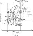
- FIGS. 5A and 5B illustrate alternative approaches for determining the stack closure pressure. Namely, FIG. 5A illustrates a graph 200 of a response of the brake system 18 based on amplitude attenuation and FIG. 5B is a graph 250 of response of the brake system 18 based on a phase lag. It is to be appreciated that while amplitude attenuation and the phase lag are illustrated in separate figures, the brake system 18 may exhibit both responses. In other words, amplitude attenuation and phase lag are not mutually exclusive of one another. Referring now to both FIGS.
- a dashed reference line is the fluid pressure indicated by the valve command 196 and the solid line represents an output of the proportional electrical signal 198, which is generated by the one or more pressure transducers 28.
- the fluid pressure indicated by valve command 196 is in the form of a periodic signal.
- the periodic signal includes a sine waveform.
- a sine waveform is illustrated, it is to be appreciated that other types of periodic signals may be used as well.
- the periodic signal includes one of the following: a sine waveform, step waveform, an impulse waveform, a triangular waveform, and a sawtooth waveform.
- the periodic signal may also be referred to as a dithering input since the value of the periodic signal switches between respective maximum and minimum values.
- the fluid pressure indicated by valve command 196 includes a maximum value 202 and a minimum value 204 for each period P n of the periodic signal (where FIG. 5 illustrates multiple periods P 1 , P 2 , etc.).
- the output of the proportional electrical signal 198 includes a maximum value 212 and a minimum value 214 for each period p n of the periodic signal as well.
- the valve command 52 instructs the valve 26 to modulate the fluid pressure of the brake system 18 based on a waveform of the periodic signal, which results in modulating the amount of brake fluid supplied to the cylinder 40.
- the valve 26 modulates the fluid pressure of the brake system 18 based on a sine waveform.
- the valve command 52 also instructs the valve 26 to increase the fluid pressure of the brake system 18 at a fixed rate while simultaneously modulating the fluid pressure as well. This results in an increase in the amount of brake fluid supplied to the cylinder 40 at the fixed rate while simultaneously modulating the amount of brake fluid.
- the maximum value 202 and the minimum value 204 of each period P n of the fluid pressure indicated by valve command 196 increases in value.
- the maximum value 202 as well as the minimum value 204 of the third period P 3 is greater than the respective maximum value 202 and minimum value 204 of the second period P 2 .
- the maximum value 202 as well as the minimum value 204 of the fourth period P 4 is greater than the respective values for the maximum value 202 and the minimum value 204 of the third period P 3 .
- the valve 26 initially starts to increase the amount of brake fluid to the cylinder 40, which is a result of increasing the fluid pressure in the brake system 18 in response to receiving the valve command 52.
- the output of the proportional electrical signal 198 (which is generated by the one or more pressure transducers 28) does not match the fluid pressure indicated by valve command 196 until the stack closure pressure 300 is reached. This is because the frequency response of the brake system 18 commensurately changes in response to a change in the compliance of the brake fluid within the cylinder 40.
- the fluid pressure of the pressurized chamber 48 of the cylinder 40 follows the waveform the periodic signal of the valve command 52. Specifically, the phase P n of the fluid pressure indicated by valve command 196 and the phase p n of the output of the proportional electrical signal 198 are substantially synchronized with one another before the stack closure pressure 300 is achieved. However, after stack closure pressure 300 is achieved, a phase lag between the valve command 196 and the proportional electrical signal 198 is observed. It is to be appreciated that the phase lag is generally not visible in FIG. 5A due to the x-axis and y-axis scales. Instead, the phase lag is visible in FIG. 5B and is described below. Referring back to FIG.
- the maximum value 202 and the minimum value 204 of a specific phase P n of the fluid pressure indicated by valve command 196 does not match the maximum value 212 and the minimum value 216 of the output of the proportional electrical signal 198 of the respective phase p n until the proportional electrical signal 58 is about equal to the stack closure pressure 300.
- a pressure amplitude a n of a respective phase p n of the output of the proportional electrical signal 198 is less than a valve amplitude A n of a single phase P n of the fluid pressure indicated by valve command 196 until the proportional electrical signal 58 generated by the pressure transducers 28 is about equal to the stack closure pressure 300.
- the pressure amplitude a n of a respective phase p n of the output of the proportional electrical signal 198 is substantially the same as the then the valve amplitude A n defined by a single phase P n of the fluid pressure indicated by valve command 196.
- the control module 22 determines the valve amplitude A n of a single phase P n of the commanded pressure indicated by valve command 196 and the pressure amplitude a n of the respective phase p n of the output of the proportional electrical signal 198 generated by the one or more pressure transducers 28. The control module 22 then compares the valve amplitude A n to the pressure amplitude a n . In response to determining the valve amplitude A n and the pressure amplitude a n are about equal to one another, the control module 22 determines the output of the proportional electrical signal 198 is about equal to the stack closure pressure 300.
- control module 22 determines the fluid pressure indicated by valve command 196 and the output of the proportional electrical signal 198 are about equal to one another when the difference in the first amplitude A n and the second amplitude a n are equal to or less than about twenty seven percent (27%).
- this value is merely exemplary in nature. Indeed, the differences in amplitude between the fluid pressure indicated by valve command 196 and the output of the proportional electrical signal 198 may vary based on the precision required by a particular application.
- the control module 22 determines a value indicated by the output of the proportional electrical signal 198 is about equal to the fluid pressure indicated by valve command 196, then the control module 22 saves the value of the output of the proportional electrical signal 198 in the memory 1034 ( FIG. 7 ) of the control module 22.
- the memory 1034 includes the threshold number plurality of previously recorded outputs of the proportional electrical signal 198.
- the threshold number plurality of previously recorded outputs of the proportional electrical signal 198 is two.
- the stack closure pressure of the brake system 18 is an average of the output of the proportional electrical signal 198 and the two previously recorded outputs of the proportional electrical signal 198.
- FIG. 6 is a process flow diagram illustrating an alternative method 400 for determining the stack closure pressure of the brake stack 32 based on the periodic signal shown in FIG. 5A based on amplitude attenuation.
- the method 400 begins at block 402.
- the control module 22 initiates the method 400. For example, if the vehicle 10 is an aircraft, then the method 400 is initiated if the aircraft is in the air and the landing gear (not shown) of the aircraft is deployed. Once the method 400 is initiated, then the method 400 proceeds to block 404.
- control module 22 In block 404, the control module 22 generates the valve command 52 instructing the valve 56 to modulate the fluid pressure of the brake system 18 and results in modulating the amount of brake fluid supplied to the cylinder 40 based on the waveform of the periodic signal, which is seen in FIG. 5 as the fluid pressure indicated by valve command 196.
- the method 400 may then proceed to block 406.
- control module 22 monitors the output of the proportional electrical signal 198 generated by the one or more pressure transducers 28. As seen in FIG. 5 , the output of the proportional electrical signal 198 is not equal to the fluid pressure indicated by the valve command 196 until the stack closure pressure 300 is achieved. The method 400 may then proceed to block 408.
- control module 22 determines the fluid pressure within the cylinder 40 is at the stack closure pressure 300 in response to the output of the proportional electrical signal 198 being about equal to the fluid pressure indicated by the valve command 196, where the stack closure pressure represents the minimum amount brake pressure required to generate brake torque by the brake stack 32.
- the method 400 may then proceed to block 410.
- control module 22 saves the value the output of the proportional electrical signal 198 that is about equal to the fluid pressure indicated by the valve command 196 in the memory 1034 ( FIG. 7 ). The method 400 may then proceed to decision block 412.
- the control module 22 determines if the memory 1034 includes at least the threshold number of previously recorded outputs of the proportional electrical signal 198. For example, in one example threshold number of previously recorded outputs of the proportional electrical signal 198 is two. If the memory 1034 does not include the threshold number of previously recorded outputs of the proportional electrical signal 198, then the method 400 proceeds to block 414. In block 412, the control module 22 selects the value of the output of the proportional electrical signal 198 determined in block 408 as the brake stack pressure. Alternatively, the control module 22 may not select a brake stack pressure. The method 400 may then terminate.
- the method 400 may proceed to block 416.
- the control module 22 determines the stack closure pressure of the brake system 18 is an average of the value the output of the proportional electrical signal 198 that is about equal to the fluid pressure indicated by the valve command 196 and the previously recorded outputs of the proportional electrical signal 198. The method 400 may then terminate.
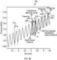
- the graph 250 in FIG. 5B illustrates the valve command 196 and the output of the proportional electrical signal 198, which is generated by the one or more pressure transducers 28.
- the valve 26 modulates the fluid pressure of the brake system 18 based on the periodic signal, which is a sine waveform.
- the valve command 52 also instructs the valve 26 to increase the fluid pressure of the brake system 18 at the fixed rate while simultaneously modulating the fluid pressure as well, which results in increasing the amount of brake fluid supplied to the cylinder 40 at the fixed rate while simultaneously modulating the amount of brake fluid.
- the fluid pressure of the pressurized chamber 48 of the cylinder 40 follows the waveform the periodic signal of the valve command 52. Specifically, the phase p n of the output of the proportional electrical signal 198 and the phase P n of the fluid pressure indicated by valve command 196 are substantially synchronized with one another before the stack closure pressure 300 is achieved. However, immediately after stack closure pressure 300 is achieved, a phase lag 304 between the valve command 196 and the proportional electrical signal 198 is present. As seen in FIG. 5A , the phase p n of the output of the proportional electrical signal 198 lags the phase P n of the fluid pressure indicated by valve command 196 immediately after the proportional electrical signal 58 ( FIG. 1 ) is about equal to the stack closure pressure 300. In other words, the phase lag 304 exists between the phase p n of the output of the proportional electrical signal 198 and the phase P n of the fluid pressure indicated by valve command 196
- the phase lag 304 shown in FIG. 5B represents a difference between the maximum value 202 of the output of the proportional electrical signal 198 and the maximum value 212 of the fluid pressure indicated by valve command 196. However, it is to be appreciated that the phase lag 304 may be represented as a difference between any two analogous points measured along the proportional electrical signal 198 and the fluid pressure indicated by valve command 196. The phase lag 304 remains constant after stack closure pressure 300 is reached.
- phase lag 304 measured between a first maximum value 202 1 of the output of the proportional electrical signal 198 and a first maximum value 212 1 of the fluid pressure indicated by valve command 196 is about the same as the phase lag 304 measured between a third maximum value 202 3 of the output of the proportional electrical signal 198 and a third maximum value 212 3 of the fluid pressure indicated by valve command 196.
- the phase lag 304 is recalculated over the life of the brake system to account for changes in the brake system 18 such as, for example, brake wear and any changes in the volume of the brake fluid.
- FIG. 7 is a process flow diagram illustrating an alternative method 500 for determining the stack closure pressure of the brake stack 32 based on phase shifting.
- the method 500 begins at block 502.
- the control module 22 initiates the method 400. Once the method 500 is initiated, then the method 400 proceeds to block 504.
- control module 22 In block 504, the control module 22 generates the valve command 52 instructing the valve 56 to modulate the fluid pressure of the brake system 18, which results in modulating the amount of brake fluid supplied to the cylinder 40 based on the waveform of the periodic signal, which is seen in FIG. 5B as the fluid pressure indicated by valve command 196.
- the method 500 may then proceed to block 506.
- control module 22 monitors the output of the proportional electrical signal 198 generated by the one or more pressure transducers 28. As seen in FIG. 5B , the output of the proportional electrical signal 198 is in phase with the fluid pressure indicated by the valve command 196 until the stack closure pressure 300 is achieved. The method 500 may then proceed to block 508.
- control module 22 detects the phase lag 304, where the phase lag 304 represents a lag in the output of the proportional electrical signal 198 generated by the one or more pressure transducers when compared to the fluid pressure indicated by the valve command 196.
- the method 500 may then proceed to block 510.
- control module 22 in response to detecting the phase lag 304, saves the value the output of the proportional electrical signal 198 generated by the one or more pressure transducers 28 immediately after the phase lag 304 is detected in the memory 1034 ( FIG. 7 ). The method 500 may then proceed to decision block 512.
- the control module 22 determines if the memory 1034 includes at least the threshold number of previously recorded outputs of the proportional electrical signal 198. For example, in one example threshold number of previously recorded outputs of the proportional electrical signal 198 is two. If the memory 1034 does not include the threshold number of previously recorded outputs of the proportional electrical signal 198, then the method 500 proceeds to block 514. In block 512, the control module 22 selects the value of the output of the proportional electrical signal 198 determined in block 510 as the brake stack pressure. Alternatively, the control module 22 may not select a brake stack pressure. The method 500 may then terminate.
- the method 500 may proceed to block 516.
- the control module 22 determines the stack closure pressure of the brake system 18 is an average of the value the output of the proportional electrical signal 198 generated by the one or more pressure transducers 28 immediately after the phase lag 304 is detected and the previously recorded outputs of the proportional electrical signal 198. The method 500 may then terminate.
- the disclosed brake system provides a relatively simple and robust approach for determining the stack closure pressure of the brake stack.
- the value of the stack closure pressure may be used as an initial pressure command, which results in a reduced amount of lag that commonly occurs in conventional brake systems when the brakes are initially applied.
- the value of the stack closure pressure is not a fixed value and may be adjusted to accommodate changes in the brake system that occur over time.
- the stack closure pressure is recalculated over the life of the brake system to account for changes in the brake system such as, for example, brake wear and any changes in the volume of the brake fluid.
- vehicles such as aircraft include more than one brake system, and each brake system may include its own individual stack closure pressure.
- the control module 22 is implemented on one or more computer devices or systems, such as exemplary computer system 1030.
- the computer system 1030 includes a processor 1032, a memory 1034, a mass storage memory device 1036, an input/output (I/O) interface 1038, and a Human Machine Interface (HMI) 1040.
- the computer system 1030 is operatively coupled to one or more external resources 1042 via the network 1026 or I/O interface 1038.
- External resources may include, but are not limited to, servers, databases, mass storage devices, peripheral devices, cloud-based network services, or any other suitable computer resource that may be used by the computer system 1030.
- the processor 1032 may include one or more devices selected from microprocessors, micro-controllers, digital signal processors, microcomputers, central processing units, field programmable gate arrays, programmable logic devices, state machines, logic circuits, analog circuits, digital circuits, or any other devices that manipulate signals (analog or digital) based on operational instructions that are stored in the memory 1034.
- Memory 1034 may include a single memory device or a plurality of memory devices including, but not limited to, read-only memory (ROM), random access memory (RAM), volatile memory, non-volatile memory, static random-access memory (SRAM), dynamic random-access memory (DRAM), flash memory, cache memory, or any other device capable of storing information.
- the mass storage memory device 1036 may include data storage devices such as a hard drive, optical drive, tape drive, volatile or non-volatile solid-state device, or any other device capable of storing information.
- the processor 1032 operates under the control of an operating system 1046 that resides in memory 1034.
- the operating system 1046 manages computer resources so that computer program code embodied as one or more computer software applications, such as an application 1048 residing in memory 1034, may have instructions executed by the processor 1032 (e.g. as a computer-implemented method).
- the processor 1032 may execute the application 1048 directly, in which case the operating system 1046 may be omitted.
- One or more data structures 1049 also reside in memory 1034, and may be used by the processor 1032, operating system 1046, or application 1048 to store or manipulate data.
- the I/O interface 1038 provides a machine interface that operatively couples the processor 1032 to other devices and systems, such as the network 1026 or external resource 1042.
- the application 1048 thereby works cooperatively with the network 1026 or external resource 1042 by communicating via the I/O interface 1038 to provide the various features, functions, applications, processes, or modules comprising examples of the disclosure.
- the application 1048 also includes program code that is executed by one or more external resources 1042, or otherwise rely on functions or signals provided by other system or network components external to the computer system 1030.
- examples of the disclosure may include applications that are located externally to the computer system 1030, distributed among multiple computers or other external resources 1042, or provided by computing resources (hardware and software) that are provided as a service over the network 1026, such as a cloud computing service.
- the HMI 1040 is operatively coupled to the processor 1032 of computer system 1030 in a known manner to allow a user to interact directly with the computer system 1030.
- the HMI 1040 may include video or alphanumeric displays, a touch screen, a speaker, and any other suitable audio and visual indicators capable of providing data to the user.
- the HMI 1040 may also include input devices and controls such as an alphanumeric keyboard, a pointing device, keypads, pushbuttons, control knobs, microphones, etc., capable of accepting commands or input from the user and transmitting the entered input to the processor 1032.
- a database 1044 may reside on the mass storage memory device 1036 and may be used to collect and organize data used by the various systems and modules described herein.
- the database 1044 may include data and supporting data structures that store and organize the data.
- the database 1044 may be arranged with any database organization or structure including, but not limited to, a relational database, a hierarchical database, a network database, or combinations thereof.
- a database management system in the form of a computer software application executing as instructions on the processor 1032 may be used to access the information or data stored in records of the database 1044 in response to a query, where a query may be dynamically determined and executed by the operating system 1046, other applications 1048, or one or more modules.
- a brake system 18 having a brake stack 32 with a stack closure pressure 82, a force member 30 positioned within a cylinder 40, a valve 52 configured to adjust fluid pressure in the brake system 18, and one or more pressure transducers 28 that generate a proportional electrical signal 198 representative of the fluid pressure within the cylinder 40, the brake system 18 comprising:
- the one or more processors 1032 are configured to execute instructions to cause the brake system 18 to: in response to determining that the valve amplitude A n and the pressure amplitude a n are about equal to one another, save the output of the proportional electrical signal 198 in the memory 1034, wherein the memory 1034 includes a plurality of previously recorded outputs of the proportional electrical signal 198.
- the one or more processors 1032 are configured to execute instructions to cause the brake system 18 to: determine the stack closure pressure 300 of the brake system 18 as an average of the output of the proportional electrical signal 198 and the plurality of previously recorded outputs of the proportional electrical signal 198.
- the brake system 18 determines the stack closure pressure 300 of the brake system 18 as an average of the output of the proportional electrical signal 198 and the plurality of previously recorded outputs of the proportional electrical signal 198 in response to the memory 1034 including a threshold number of previously recorded outputs of the proportional electrical signal 198.
- the present disclosure also relates to an aircraft, comprising a brake system according to the primary example.
- a brake system 18 having a brake stack 32 with a stack closure pressure 82, a force member 30 positioned within a cylinder 40, a valve 52 configured to adjust fluid pressure in the brake system 18, and one or more pressure transducers 28 that generate a proportional electrical signal 198 representative of the fluid pressure within the cylinder 40, the brake system 18 comprising:
- the one or more processors 1032 are configured to execute instructions to cause the brake system 18 to: in response to detecting the phase lag 304, save the output of the proportional electrical signal 198 in the memory 1034, wherein the memory 1034 includes a plurality of previously recorded outputs of the proportional electrical signal 198.
- the one or more processors 1032 are configured to execute instructions to cause the brake system 18 to: determine the stack closure pressure 300 of the brake system 18 as an average of the output of the proportional electrical signal 198 and the plurality of previously recorded outputs of the proportional electrical signal 198.
- the brake system 18 determines the stack closure pressure 300 of the brake system 18 as an average of the output of the proportional electrical signal 198 and the plurality of previously recorded outputs of the proportional electrical signal 198 in response to the memory 1034 including a threshold number of previously recorded outputs of the proportional electrical signal 198.
- the present disclosure also relates to an aircraft, comprising a brake system according to the secondary example.
- amplitude attenuation and the phase lag are illustrated in separate figures, the brake system 18 may exhibit both responses. In other words, amplitude attenuation and phase lag are not mutually exclusive of one another. Accordingly, the above primary example and secondary example may be combined.
Abstract
Description
- The present disclosure relates to brake systems. More specifically, the present disclosure relates to a brake system that determines a stack closure pressure of a brake stack based on monitoring a fluid pressure of the brake system.
- Aircraft brakes are used in a variety of situations. For example, aircraft brakes are used to slow the aircraft down during landing roll along a runway. Aircraft brakes may also be used during ground handling operations such as, for example, taxiing, steering, and parking. Aircraft brakes typically include a brake stack having a series of rotating members, which are referred to as rotors, that turn along with the wheels of the aircraft. The brake stack also includes a series of stationary members, which are referred to as stators, that are interleaved with the rotors.
- When the brake stack is compressed, friction forces are developed between the rotors and stators and a brake torque is generated. The brake torque causes the aircraft to decelerate and eventually come to a stop. It is to be appreciated that brake torque is only generated after the rotors and stators are compressed to the point they are in firm contact with one another, which is referred to as brake stack closure. Hydraulically actuated aircraft brakes require a minimum amount of hydraulic brake pressure to overcome the spring force exerted to maintain the running clearance between the brake piston and the stators to generate brake torque. The minimum amount of hydraulic brake pressure required to generate brake torque is referred to as stack closure pressure.
- Sometimes the aircraft brakes may either be underfilled or overfilled with hydraulic brake fluid. Thus, a rapid onset of brake torque results in aircraft deceleration overshoot. In contrast, underfilling results in an initial brake pressure that is too low. This results in brake onset delay that is often accompanied by pressure overshoot at the moment brake stack closure occurs.
- According to several aspects, a brake system having a brake stack with a stack closure pressure is disclosed. The brake system includes a force member positioned within a cylinder, a valve configured to adjust fluid pressure in the brake system, and one or more pressure transducers that generate a proportional electrical signal representative of the fluid pressure within the cylinder. The brake system also includes one or more processors in electronic communication with the valve and the one or more pressure transducers and a memory coupled to the one or more processors. The memory stores data comprising a database and program code that, when executed by the one or more processors, causes the brake system to generate a valve command instructing the valve to increase the fluid pressure in the brake system, which results in increasing an amount of brake fluid supplied to the cylinder at a fixed rate. The brake system is further caused to monitor an output of the proportional electrical signal generated by the one or more pressure transducers. The brake system is also caused to determine a derivative value of the output of the proportional electrical signal as the amount of brake fluid supplied to the cylinder is increased at the fixed rate. The brake system is also caused to determine a transition point of the derivative value, wherein the transition point represents when the derivative value exceeds about zero and increases to a positive value. Further, the brake system is caused to select the fluid pressure at the transition point as the stack closure pressure of the brake system.
- According to another aspect, an aircraft having a brake system is disclosed. The aircraft includes a brake stack including one or more rotors interleaved with one or more stators, a force member positioned within a cylinder, a valve configured to adjust fluid pressure in the brake system, one or more pressure transducers that generate a proportional electrical signal representative of the fluid pressure within the cylinder, one or more processors in electronic communication with the valve and the one or more pressure transducers, and a memory coupled to the one or more processors. The memory stores data comprising a database and program code that, when executed by the one or more processors, causes the brake system to generate a valve command instructing the valve to increase the fluid pressure in the brake system, which results in increasing of an amount of hydraulic brake fluid supplied to the cylinder at a fixed rate. The brake system is also caused to monitor an output of the proportional electrical signal generated by the one or more pressure transducers. The brake control system is also caused to determine a derivative value of the output of the proportional electrical signal as the amount of hydraulic brake fluid supplied to the cylinder is increased at the fixed rate. The brake control system is caused to determine a transition point of the derivative value, wherein the transition point represents when the derivative value exceeds about zero and increases to a positive value. Further, the brake control system is caused to select the fluid pressure at the transition point as a stack closure pressure of the brake system. The stack closure pressure represents a minimum amount brake pressure required to generate brake torque by the brake stack.
- In still another aspect, a method, in particular a computer-implemented method, for determining a stack closure pressure for a brake stack of a brake system is disclosed. The method includes generating, by a computer, a valve command instructing a valve to increase fluid pressure of the brake system, which results in an amount of brake fluid supplied to a cylinder at a fixed rate. A force member is positioned within the cylinder and the valve is configured to control the amount of brake fluid supplied to the cylinder. The method also includes monitoring, by the computer, an output of a proportional electrical signal generated by one or more pressure transducers. The proportional electrical signal is representative of the fluid pressure within the cylinder. The method also includes determining a derivative value of the output of the proportional electrical signal as the amount of brake fluid supplied to the cylinder is increased at the fixed rate. The method further includes determining a transition point of the derivative value, wherein the transition point represents when the derivative value exceeds about zero and increases to a positive value. Further, the method includes selecting the fluid pressure at the transition point as the stack closure pressure of the brake system.
- The features, functions, and advantages that have been discussed may be achieved independently in various examples or may be combined in other examples further details of which can for instance be seen with reference to the following description and drawings.
- The drawings described herein are for illustration purposes only and are not intended to limit the scope of the present disclosure in any way.
-
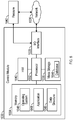
FIG. 1 is a schematic diagram of a vehicle including the disclosed brake system, where the brake system has a control module, a valve, a force member disposed within a cylinder, a brake stack, and a fluid reservoir according to an example; -
FIG. 2 is a graph illustrating a procedure for determining a stack closure pressure of the brake stack illustrated inFIG. 1 according to an example; -
FIG. 3A is a graph illustrating the fluid pressure of the brake fluid when the procedure shown inFIG. 2 is performed according to an example; -
FIG. 3B is a graph illustrating the brake torque generated by the brake stack when the procedure shown inFIG. 2 is performed according to an example; -
FIG. 4 is a process flow diagram illustrating a method for determining the brake stack closure according to an example; -
FIG. 5A is a graph illustrating an alternative procedure for determining the stack closure pressure of the brake stack shown inFIG. 1 based on amplitude attenuation according to an example; -
FIG. 5B is a graph illustrating another procedure for determining the stack closure pressure of the brake stack shown inFIG. 1 based on a phase lag according to an example; -
FIG. 6 is a process flow diagram illustrating an alternative method for determining the brake stack closure based on the amplitude attenuation seen inFIG. 5A according to an example; -
FIG. 7 is process flow diagram illustrating an alternative method for determining the brake stack closure based on the phase lag seen inFIG. 5B according to an example; and -
FIG. 8 is an illustration of a computer system used by the brake system ofFIG. 1 according to an example. - The present disclosure is directed towards a system and method for determining a stack closure pressure of a brake stack. The brake stack is part of a brake system for a vehicle. The stack closure pressure represents a minimum amount of brake pressure required to generate brake torque, where the brake torque causes the vehicle to either decelerate or come to a stop. The stack closure pressure is then used as an initial commanded pressure by the brake system. It is to be appreciated that the initial commanded pressure may be used in an autobrake control system. Setting the stack closure pressure as the initial commanded pressure of the brake system reduces the lag that commonly occurs in conventional open loop brake systems when the brakes are initially applied. The stack closure pressure is recalculated over time to account for changes in the brake system such as, for example, brake wear and any changes in the volume of the brake fluid.
- The following description is merely exemplary in nature and is not intended to limit the present disclosure, application, or uses.
- Referring to
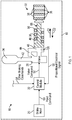
FIG. 1 , a schematic diagram of avehicle 10 having abrake system 18 is illustrated. Thebrake system 18 includes abrake input 20, acontrol module 22, avalve 26, one ormore pressure transducers 28, aforce member 30, a brake heat stack, which is referred to as abrake stack 32, and afluid reservoir 34. Thecontrol module 22 is in electronic communication with thebrake input 20, thevalve 26, and thepressure transducers 28. Theforce member 30 is configured to translate back and forth in a linear motion within acylinder 40. Specifically, theforce member 30 translates within thecylinder 40 in response to a change in fluid pressure within apressurized chamber 48 of thecylinder 40, which is explained in greater detail below and is shown inFIGS. 2-4 . Thebrake system 18 also includes ahigh pressure conduit 42 that fluidly connects thefluid reservoir 34 to thevalve 26 and areturn conduit 44 that fluidly connects thepressurized chamber 48 of thecylinder 40 to thevalve 26. The pressure transducers 28 monitor the fluid pressure within thecylinder 40, and more specifically the fluid pressure of thepressurized chamber 48 within thecylinder 40. - The
brake stack 32 includes one ormore rotors 36 interleaved with one or more stators 38. A brake stack closure represents a state of thebrake stack 32 where therotors 36 and stators 38 bear frictionally upon one another, and any further compression of thebrake stack 32 creates a brake torque that resists movement of thevehicle 10. As explained below, thecontrol module 22 determines a stack closure pressure of thebrake stack 32. The stack closure pressure represents a minimum amount brake pressure required to generate the brake torque by thebrake stack 32. - In one example, the
vehicle 10 is an aircraft and thebrake system 18 employs hydraulic braking fluid for transferring hydraulic pressure to thebrake stack 32. However, it is to be appreciated that thevehicle 10 is not limited to an aircraft. It is also to be appreciated that whileFIG. 1 illustrates only asingle brake system 18, an aircraft may actually includemultiple brake systems 18. For example, an aircraft may include separate brake systems that correspond to the left and right wheels of an aircraft. Thus, individual stack closure pressures are determined for eachindividual brake system 18. - The disclosed
brake system 18 is any brake system including a dead band space. The dead band space represents the displacement a brake piston (i.e., the force member 30) undergoes as a user initially exerts force upon the brake pedal, but the force is not transmitted to thebrake stack 32. Therefore, thebrake system 18 is not limited to hydraulic systems. For example, in an alternative example, thebrake system 18 may be a pneumatically based brake system instead of a hydraulic brake system. Accordingly, the brake fluid is a liquid or a gas. - In one example, the
brake input 20 is a brake pedal. An operator depresses the brake pedal manually to create aninput command 50 received by thecontrol module 22. Theinput command 50 represents an amount of braking requested by thebrake system 18. Thus, if a manual brake pedal is employed, then an operator indicates the amount of braking requested by thebrake system 18 using the brake pedal. Alternatively, instead of manual control, theinput command 50 is generated by an autobrake algorithm, where autobrake instructions are saved in amemory 1034 of the control module 22 (thememory 1034 is shown inFIG. 7 ). - In response to receiving the
input command 50 from thebrake input 20, thecontrol module 22 determines avalve command 52. Specifically, thecontrol module 22 determines thevalve command 52 based on theinput command 50 from thebrake input 20. Thevalve command 52 may also be determined based on a plurality of other braking commands 54. Some examples of the other braking commands 54 include, but are not limited to, autobrake, gear retract braking, or parking brake. For example, if the autobrake algorithm is employed, then the autobrake instructions generate theinput command 50, where theinput command 50 represents the amount of braking requested by thebrake system 18. Thecontrol module 22 then determines thevalve command 52 based on at least theinput command 50. Thevalve command 52 is sent to thevalve 26, where thevalve 26 is configured to adjust the fluid pressure in thebrake system 18. In response to receiving thevalve command 52 from thecontrol module 22, thevalve 26 adjusts an amount of fluid pressure supplied to thebrake system 18, which results in an increase in an amount of the brake fluid contained within thepressurized chamber 48. Specifically, thevalve 26 either increases or decreases the amount of pressure supplied to thebrake system 18. - The
force member 30 may be a piston that includes anend portion 68. A biasingmember 66, such as a coil spring, may be placed within thecylinder 40. Theforce member 30 overcomes a biasing force exerted by the biasingmember 66 to translate in a first direction D1 towards thebrake stack 32. As theforce member 30 translates in the first direction D1 theend portion 68 of theforce member 30 eventually abuts against and exerts a compressive force upon thebrake stack 32. For example, referring toFIGS. 1 and2 , actuating thevalve 26 results in an increase in the amount of brake fluid supplied to thecylinder 40 until the fluid pressure of thepressurized chamber 48 is at least equal to the stack closure pressure (the stack closure pressure is labeled inFIG. 2 as transition point C). Once the fluid pressure of thepressurized chamber 48 is at least equal to the stack closure pressure, any additional brake fluid supplied to thepressurized chamber 48 results in theend portion 68 of theforce member 30 further compressing thebrake stack 32. Theforce member 30 continues to compress thebrake stack 32 until the fluid pressure of thepressurized chamber 48 reaches a maximum pressure value 74 (FIG. 2 ). Thus, when the fluid pressure of thepressurized chamber 48 is at themaximum pressure value 74, the brake stack 32 (FIG. 1 ) is fully compressed. - The pressure transducers 28 generate a proportional
electrical signal 58 representative of the fluid pressure in thepressurized chamber 48 of thecylinder 40. The proportionalelectrical signal 58 is received by thecontrol module 22. For example, in one non-limiting example the proportionalelectrical signal 58 is a current value ranging from about four to about twenty milliamps. Although current is described, it is to be appreciated that thepressure transducers 28 may output other electrical signals instead. That is, the proportionalelectrical signal 58 is selected from a current value, a capacitance value, or a voltage value. For example, in one non-limiting example, thevalve 26 is a servo valve and thevalve command 52 is a milliamp signal. - An approach to determine the stack closure pressure of the
brake stack 32 is now described.FIG. 2 is agraph 70 illustrating an exemplary procedure to determine the stack closure pressure, where the x-axis represents a brake fluid compliance displacement within thepressurized chamber 48 of thecylinder 40 and the y-axis represents the fluid pressure as measured by thepressure transducers 28. Referring to bothFIGS. 1 and2 , the brake fluid compliance displacement represents the displacement of theforce member 30 within thecylinder 40, where positive displacement is movement in the first direction D1 and negative displacement is movement in a second direction D2. As seen inFIG. 2 , the second direction D2 is opposite the first direction D1 and is oriented in a direction away from thebrake stack 32. - The
control module 22 generates avalve command 52 instructing thevalve 26 to increase the fluid pressure of thebrake system 18 and results in an increase in the amount of brake fluid supplied to thecylinder 40 at a fixed rate. The fixed rate represents a steady-state amount of brake fluid supplied to thecylinder 40. Thegraph 70 includes a line representing anoutput 72 of the proportionalelectrical signal 58 generated by the one ormore pressure transducers 28. Theoutput 72 is divided into two portions, namely portion A and portion B. During portion A, thecontrol module 22 instructs thevalve 26 to increase the fluid pressure, which results in an increase in the amount of brake fluid supplied to thecylinder 40 at the fixed rate. However, as seen inFIG. 2 , although the brake fluid compliance displacement along the y-axis increases, there is only a negligible increase in the brake pressure. That is, the relationship between the hydraulic brake fluid compliance displacement and the fluid pressure has a derivative value (i.e., the slope of a line) of about zero, i.e. a negligible derivative value. For purposes of the disclosure, about zero may include positive fluid pressure values, e.g. being negligible fluid pressure values. Importantly, whether a fluid pressure value may be considered about zero and/or may be considered a negligible fluid pressure value depends on the operating range of fluid pressure values of a system. For example, in an example any fluid pressure values that are less than about 300 psi (2068 kPa) may be considered about zero, and/or may be considered as negligible fluid pressure values. In one example, thecontrol module 22 filters derivative values of theoutput 72 of the proportionalelectrical signal 58 that are below a threshold pressure value to about zero. The threshold pressure value represents negligible changes in the brake pressure that may be disregarded for purposes of detecting the stack closure pressure. That is, in response to determining the derivative value of theoutput 72 of the proportionalelectrical signal 58 is below the threshold pressure value, thecontrol module 22 sets the derivative value to about zero. For example, in one example the threshold pressure value is about 200 pounds per square inch (psi) (about 1379 kPa). - Portion A terminates at the transition point C. The transition point C represents when the derivative value of the fluid pressure exceeds about zero and increases to a positive value. In an example, the positive value is equal to or greater than about 300 psi (2068 kPa). The transition point C represents the stack closure pressure of the
brake system 18. As mentioned above, the stack closure pressure represents the minimum amount brake pressure required to generate brake torque by thebrake stack 32. - It is to be appreciated that while portions A and B of the
output 72 of the proportionalelectrical signal 58 generated by the one ormore pressure transducers 28 include different derivative values, the rate at which brake fluid is supplied to thecylinder 40 does not change. In other words, the brake fluid continues to be supplied to thecylinder 40 at the fixed rate. - In one example, the
control module 22 selects the fluid pressure at the transition point C as the stack closure pressure of thebrake system 18, where the stack closure pressure represents the minimum amount brake pressure required to generate brake torque by thebrake stack 32. The fluid pressure at the transition point is saved in the memory 1034 (FIG. 7 ) of thecontrol module 22, where thememory 1034 stores the magnitude of previously recorded derivative values of the fluid pressure, which are referred to as a plurality of previously recorded values at the transition point C. Thus, the stack closure pressure of thebrake system 18 is an average of the fluid pressure at the transition point and the plurality of previously recorded values at the transition point C. For example, in one example, the magnitude of at least three fluid pressures are stored in the memory of thecontrol module 22 before the stack closure pressure is determined by thecontrol module 22. It is to be appreciated that the stack closure pressure may be adjusted over time to take factors such as, for example, wear in thebrake stack 32 and a change in the volume of the brake fluid into account. -
FIG. 3A shows agraph 80 illustrating a relationship between fluid pressure of thepressurized chamber 48 and time during the procedure shown inFIG. 2. FIG. 3A also illustratesstack closure pressure 82 and themaximum pressure value 74. Thestack closure pressure 82 represents the minimum amount of brake pressure required to generate brake torque, and themaximum pressure value 74 represents the maximum amount of brake pressure thebrake system 18 may command. That is, at themaximum pressure value 74, the brake stack 32 (FIG. 1 ) is fully compressed.FIG. 3B shows agraph 90 illustrating a relationship between brake torque and time during the procedure shown inFIG. 2. FIG. 3B also illustrates a zerotorque point 92. The zerotorque point 92 represents when the brake stack 32 (FIG. 1 ) starts to create brake torque to cause thevehicle 10 to decelerate or stop. -
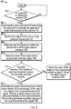
FIG. 4 is an exemplary process flow diagram illustrating amethod 100 for determining the stack closure pressure of thebrake system 18. Referring to bothFIGS. 1 and4 , themethod 100 begins atblock 102. Inblock 102, thecontrol module 22 determines if themethod 100 is initiated. For example, if thevehicle 10 is an aircraft, then themethod 100 is initiated if the aircraft is in the air and the landing gear (not shown) of the aircraft is deployed. Once themethod 100 is initiated, then themethod 100 proceeds to block 104. - In
block 104, thecontrol module 22 generates thevalve command 52 instructing thevalve 26 to increase the fluid pressure of thebrake system 18 and results in an increase in the amount of brake fluid supplied to thecylinder 40 the amount of brake fluid supplied to thecylinder 40 at the fixed rate. Themethod 100 may then proceed to block 106. - In
block 106, thecontrol module 22 monitors the output 72 (FIG. 2 ) of the proportionalelectrical signal 58 generated by the one ormore pressure transducers 28. Themethod 100 may then proceed to block 108. - In
block 108, thecontrol module 22 determines the derivative value of the output 72 (FIG. 2 ) of the proportionalelectrical signal 58 generated by the one ormore pressure transducers 28. It is to be appreciated that the proportionalelectrical signal 58 is monitored by thecontrol module 22 as thevalve 26 increases the amount of brake fluid supplied to thecylinder 40 at the fixed rate. Themethod 100 may then proceed to block 110. - In
block 110, thecontrol module 22 determines the transition point C of the derivative value, where the transition point C occurs when the derivative value exceeds about zero and increases to a positive value. Themethod 100 may then proceed to block 112. - In
block 112, thecontrol module 22 saves the transition point C determined inblock 110 in the memory 1034 (FIG. 7 ). The method may then proceed todecision block 114. - In
decision block 114, thecontrol module 22 determines if thememory 1034 includes at least the threshold number of previously recorded fluid pressures at the transition point. For example, in one example threshold number of previously recorded fluid pressures is two. Therefore, there are three total fluid pressures saved in thememory 1034. If thememory 1034 does not include the threshold number of previously recorded values, then themethod 100 proceeds to block 116. Inblock 116, thecontrol module 22 selects the fluid pressure at the transition point C determined inblock 110 as the brake stack pressure. Alternatively, thecontrol module 22 may not select a brake stack pressure. Themethod 100 may then terminate. - If the
memory 1034 includes the threshold number of previously recorded values, then themethod 100 may proceed to block 118. Inblock 118, thecontrol module 22 determines the stack closure pressure of thebrake system 18 is an average of the fluid pressure at the transition point C and the plurality of previously recorded values at the transition point C. Themethod 100 may then terminate. -
FIGS. 5A and5B illustrate alternative approaches for determining the stack closure pressure. Namely,FIG. 5A illustrates agraph 200 of a response of thebrake system 18 based on amplitude attenuation andFIG. 5B is agraph 250 of response of thebrake system 18 based on a phase lag. It is to be appreciated that while amplitude attenuation and the phase lag are illustrated in separate figures, thebrake system 18 may exhibit both responses. In other words, amplitude attenuation and phase lag are not mutually exclusive of one another. Referring now to bothFIGS. 1 and5A , a dashed reference line is the fluid pressure indicated by thevalve command 196 and the solid line represents an output of the proportionalelectrical signal 198, which is generated by the one ormore pressure transducers 28. The fluid pressure indicated byvalve command 196 is in the form of a periodic signal. For example, in the example as shown inFIG. 5A , the periodic signal includes a sine waveform. Although a sine waveform is illustrated, it is to be appreciated that other types of periodic signals may be used as well. In an example, the periodic signal includes one of the following: a sine waveform, step waveform, an impulse waveform, a triangular waveform, and a sawtooth waveform. - The periodic signal may also be referred to as a dithering input since the value of the periodic signal switches between respective maximum and minimum values. Specifically, the fluid pressure indicated by
valve command 196 includes amaximum value 202 and aminimum value 204 for each period Pn of the periodic signal (whereFIG. 5 illustrates multiple periods P1, P2, etc.). Similarly, the output of the proportionalelectrical signal 198 includes amaximum value 212 and a minimum value 214 for each period pn of the periodic signal as well. - The
valve command 52 instructs thevalve 26 to modulate the fluid pressure of thebrake system 18 based on a waveform of the periodic signal, which results in modulating the amount of brake fluid supplied to thecylinder 40. For example, in the example as shown, thevalve 26 modulates the fluid pressure of thebrake system 18 based on a sine waveform. Thevalve command 52 also instructs thevalve 26 to increase the fluid pressure of thebrake system 18 at a fixed rate while simultaneously modulating the fluid pressure as well. This results in an increase in the amount of brake fluid supplied to thecylinder 40 at the fixed rate while simultaneously modulating the amount of brake fluid. In other words, as time progresses, themaximum value 202 and theminimum value 204 of each period Pn of the fluid pressure indicated byvalve command 196 increases in value. For example, themaximum value 202 as well as theminimum value 204 of the third period P3 is greater than the respectivemaximum value 202 andminimum value 204 of the second period P2. Likewise, themaximum value 202 as well as theminimum value 204 of the fourth period P4 is greater than the respective values for themaximum value 202 and theminimum value 204 of the third period P3. - Continuing to refer to
FIGS. 1 and5A , thevalve 26 initially starts to increase the amount of brake fluid to thecylinder 40, which is a result of increasing the fluid pressure in thebrake system 18 in response to receiving thevalve command 52. However, the output of the proportional electrical signal 198 (which is generated by the one or more pressure transducers 28) does not match the fluid pressure indicated byvalve command 196 until thestack closure pressure 300 is reached. This is because the frequency response of thebrake system 18 commensurately changes in response to a change in the compliance of the brake fluid within thecylinder 40. - The fluid pressure of the
pressurized chamber 48 of thecylinder 40 follows the waveform the periodic signal of thevalve command 52. Specifically, the phase Pn of the fluid pressure indicated byvalve command 196 and the phase pn of the output of the proportionalelectrical signal 198 are substantially synchronized with one another before thestack closure pressure 300 is achieved. However, afterstack closure pressure 300 is achieved, a phase lag between thevalve command 196 and the proportionalelectrical signal 198 is observed. It is to be appreciated that the phase lag is generally not visible inFIG. 5A due to the x-axis and y-axis scales. Instead, the phase lag is visible inFIG. 5B and is described below. Referring back toFIG. 5A , themaximum value 202 and theminimum value 204 of a specific phase Pn of the fluid pressure indicated byvalve command 196 does not match themaximum value 212 and the minimum value 216 of the output of the proportionalelectrical signal 198 of the respective phase pn until the proportionalelectrical signal 58 is about equal to thestack closure pressure 300. - As seen in
FIG. 5A , a pressure amplitude an of a respective phase pn of the output of the proportionalelectrical signal 198 is less than a valve amplitude An of a single phase Pn of the fluid pressure indicated byvalve command 196 until the proportionalelectrical signal 58 generated by thepressure transducers 28 is about equal to thestack closure pressure 300. However, after thestack closure pressure 300 is achieved, the pressure amplitude an of a respective phase pn of the output of the proportionalelectrical signal 198 is substantially the same as the then the valve amplitude An defined by a single phase Pn of the fluid pressure indicated byvalve command 196. Accordingly, thecontrol module 22 determines the valve amplitude An of a single phase Pn of the commanded pressure indicated byvalve command 196 and the pressure amplitude an of the respective phase pn of the output of the proportionalelectrical signal 198 generated by the one ormore pressure transducers 28. Thecontrol module 22 then compares the valve amplitude An to the pressure amplitude an. In response to determining the valve amplitude An and the pressure amplitude an are about equal to one another, thecontrol module 22 determines the output of the proportionalelectrical signal 198 is about equal to thestack closure pressure 300. - In one non-limiting example, the
control module 22 determines the fluid pressure indicated byvalve command 196 and the output of the proportionalelectrical signal 198 are about equal to one another when the difference in the first amplitude An and the second amplitude an are equal to or less than about twenty seven percent (27%). However, it is to be appreciated that this value is merely exemplary in nature. Indeed, the differences in amplitude between the fluid pressure indicated byvalve command 196 and the output of the proportionalelectrical signal 198 may vary based on the precision required by a particular application. - In one example, once the
control module 22 determines a value indicated by the output of the proportionalelectrical signal 198 is about equal to the fluid pressure indicated byvalve command 196, then thecontrol module 22 saves the value of the output of the proportionalelectrical signal 198 in the memory 1034 (FIG. 7 ) of thecontrol module 22. In one example, thememory 1034 includes the threshold number plurality of previously recorded outputs of the proportionalelectrical signal 198. As mentioned above, in one example the threshold number plurality of previously recorded outputs of the proportionalelectrical signal 198 is two. Thus, the stack closure pressure of thebrake system 18 is an average of the output of the proportionalelectrical signal 198 and the two previously recorded outputs of the proportionalelectrical signal 198. -
FIG. 6 is a process flow diagram illustrating analternative method 400 for determining the stack closure pressure of thebrake stack 32 based on the periodic signal shown inFIG. 5A based on amplitude attenuation. Referring toFIGS. 1 ,5A , and6 , themethod 400 begins atblock 402. Inblock 402, thecontrol module 22 initiates themethod 400. For example, if thevehicle 10 is an aircraft, then themethod 400 is initiated if the aircraft is in the air and the landing gear (not shown) of the aircraft is deployed. Once themethod 400 is initiated, then themethod 400 proceeds to block 404. - In
block 404, thecontrol module 22 generates thevalve command 52 instructing the valve 56 to modulate the fluid pressure of thebrake system 18 and results in modulating the amount of brake fluid supplied to thecylinder 40 based on the waveform of the periodic signal, which is seen inFIG. 5 as the fluid pressure indicated byvalve command 196. Themethod 400 may then proceed to block 406. - In
block 406, thecontrol module 22 monitors the output of the proportionalelectrical signal 198 generated by the one ormore pressure transducers 28. As seen inFIG. 5 , the output of the proportionalelectrical signal 198 is not equal to the fluid pressure indicated by thevalve command 196 until thestack closure pressure 300 is achieved. Themethod 400 may then proceed to block 408. - In
block 408, thecontrol module 22 determines the fluid pressure within thecylinder 40 is at thestack closure pressure 300 in response to the output of the proportionalelectrical signal 198 being about equal to the fluid pressure indicated by thevalve command 196, where the stack closure pressure represents the minimum amount brake pressure required to generate brake torque by thebrake stack 32. Themethod 400 may then proceed to block 410. - In
block 410, thecontrol module 22 saves the value the output of the proportionalelectrical signal 198 that is about equal to the fluid pressure indicated by thevalve command 196 in the memory 1034 (FIG. 7 ). Themethod 400 may then proceed todecision block 412. - In
decision block 412, thecontrol module 22 determines if thememory 1034 includes at least the threshold number of previously recorded outputs of the proportionalelectrical signal 198. For example, in one example threshold number of previously recorded outputs of the proportionalelectrical signal 198 is two. If thememory 1034 does not include the threshold number of previously recorded outputs of the proportionalelectrical signal 198, then themethod 400 proceeds to block 414. Inblock 412, thecontrol module 22 selects the value of the output of the proportionalelectrical signal 198 determined inblock 408 as the brake stack pressure. Alternatively, thecontrol module 22 may not select a brake stack pressure. Themethod 400 may then terminate. - If the
memory 1034 includes the threshold number of outputs of the proportionalelectrical signal 198, then themethod 400 may proceed to block 416. Inblock 416, thecontrol module 22 determines the stack closure pressure of thebrake system 18 is an average of the value the output of the proportionalelectrical signal 198 that is about equal to the fluid pressure indicated by thevalve command 196 and the previously recorded outputs of the proportionalelectrical signal 198. Themethod 400 may then terminate. - Referring now to
FIGS. 1 and5B , the phase lag is now described. Specifically, thegraph 250 inFIG. 5B illustrates thevalve command 196 and the output of the proportionalelectrical signal 198, which is generated by the one ormore pressure transducers 28. Thevalve 26 modulates the fluid pressure of thebrake system 18 based on the periodic signal, which is a sine waveform. Thevalve command 52 also instructs thevalve 26 to increase the fluid pressure of thebrake system 18 at the fixed rate while simultaneously modulating the fluid pressure as well, which results in increasing the amount of brake fluid supplied to thecylinder 40 at the fixed rate while simultaneously modulating the amount of brake fluid. - The fluid pressure of the
pressurized chamber 48 of thecylinder 40 follows the waveform the periodic signal of thevalve command 52. Specifically, the phase pn of the output of the proportionalelectrical signal 198 and the phase Pn of the fluid pressure indicated byvalve command 196 are substantially synchronized with one another before thestack closure pressure 300 is achieved. However, immediately afterstack closure pressure 300 is achieved, aphase lag 304 between thevalve command 196 and the proportionalelectrical signal 198 is present. As seen inFIG. 5A , the phase pn of the output of the proportionalelectrical signal 198 lags the phase Pn of the fluid pressure indicated byvalve command 196 immediately after the proportional electrical signal 58 (FIG. 1 ) is about equal to thestack closure pressure 300. In other words, thephase lag 304 exists between the phase pn of the output of the proportionalelectrical signal 198 and the phase Pn of the fluid pressure indicated byvalve command 196 - The
phase lag 304 shown inFIG. 5B represents a difference between themaximum value 202 of the output of the proportionalelectrical signal 198 and themaximum value 212 of the fluid pressure indicated byvalve command 196. However, it is to be appreciated that thephase lag 304 may be represented as a difference between any two analogous points measured along the proportionalelectrical signal 198 and the fluid pressure indicated byvalve command 196. Thephase lag 304 remains constant afterstack closure pressure 300 is reached. In other words, thephase lag 304 measured between a firstmaximum value 2021 of the output of the proportionalelectrical signal 198 and a firstmaximum value 2121 of the fluid pressure indicated byvalve command 196 is about the same as thephase lag 304 measured between a thirdmaximum value 2023 of the output of the proportionalelectrical signal 198 and a thirdmaximum value 2123 of the fluid pressure indicated byvalve command 196. However, it is to be appreciated that thephase lag 304 is recalculated over the life of the brake system to account for changes in thebrake system 18 such as, for example, brake wear and any changes in the volume of the brake fluid. -
FIG. 7 is a process flow diagram illustrating analternative method 500 for determining the stack closure pressure of thebrake stack 32 based on phase shifting. Referring toFIGS. 1 ,5B , and6 , themethod 500 begins atblock 502. Inblock 502, thecontrol module 22 initiates themethod 400. Once themethod 500 is initiated, then themethod 400 proceeds to block 504. - In
block 504, thecontrol module 22 generates thevalve command 52 instructing the valve 56 to modulate the fluid pressure of thebrake system 18, which results in modulating the amount of brake fluid supplied to thecylinder 40 based on the waveform of the periodic signal, which is seen inFIG. 5B as the fluid pressure indicated byvalve command 196. Themethod 500 may then proceed to block 506. - In
block 506, thecontrol module 22 monitors the output of the proportionalelectrical signal 198 generated by the one ormore pressure transducers 28. As seen inFIG. 5B , the output of the proportionalelectrical signal 198 is in phase with the fluid pressure indicated by thevalve command 196 until thestack closure pressure 300 is achieved. Themethod 500 may then proceed to block 508. - In
block 508, thecontrol module 22 detects thephase lag 304, where thephase lag 304 represents a lag in the output of the proportionalelectrical signal 198 generated by the one or more pressure transducers when compared to the fluid pressure indicated by thevalve command 196. Themethod 500 may then proceed to block 510. - In
block 510, in response to detecting thephase lag 304, thecontrol module 22 saves the value the output of the proportionalelectrical signal 198 generated by the one ormore pressure transducers 28 immediately after thephase lag 304 is detected in the memory 1034 (FIG. 7 ). Themethod 500 may then proceed todecision block 512. - In
decision block 512, thecontrol module 22 determines if thememory 1034 includes at least the threshold number of previously recorded outputs of the proportionalelectrical signal 198. For example, in one example threshold number of previously recorded outputs of the proportionalelectrical signal 198 is two. If thememory 1034 does not include the threshold number of previously recorded outputs of the proportionalelectrical signal 198, then themethod 500 proceeds to block 514. Inblock 512, thecontrol module 22 selects the value of the output of the proportionalelectrical signal 198 determined inblock 510 as the brake stack pressure. Alternatively, thecontrol module 22 may not select a brake stack pressure. Themethod 500 may then terminate. - If the
memory 1034 includes the threshold number of outputs of the proportionalelectrical signal 198, then themethod 500 may proceed to block 516. Inblock 516, thecontrol module 22 determines the stack closure pressure of thebrake system 18 is an average of the value the output of the proportionalelectrical signal 198 generated by the one ormore pressure transducers 28 immediately after thephase lag 304 is detected and the previously recorded outputs of the proportionalelectrical signal 198. Themethod 500 may then terminate. - Referring generally to the figures, the disclosed brake system provides a relatively simple and robust approach for determining the stack closure pressure of the brake stack. The value of the stack closure pressure may be used as an initial pressure command, which results in a reduced amount of lag that commonly occurs in conventional brake systems when the brakes are initially applied. Furthermore, it is to be appreciated that the value of the stack closure pressure is not a fixed value and may be adjusted to accommodate changes in the brake system that occur over time. Specifically, the stack closure pressure is recalculated over the life of the brake system to account for changes in the brake system such as, for example, brake wear and any changes in the volume of the brake fluid. It is to be appreciated that vehicles such as aircraft include more than one brake system, and each brake system may include its own individual stack closure pressure.
- Referring now to
FIG. 7 , thecontrol module 22 is implemented on one or more computer devices or systems, such asexemplary computer system 1030. Thecomputer system 1030 includes aprocessor 1032, amemory 1034, a massstorage memory device 1036, an input/output (I/O)interface 1038, and a Human Machine Interface (HMI) 1040. Thecomputer system 1030 is operatively coupled to one or moreexternal resources 1042 via thenetwork 1026 or I/O interface 1038. External resources may include, but are not limited to, servers, databases, mass storage devices, peripheral devices, cloud-based network services, or any other suitable computer resource that may be used by thecomputer system 1030. - The
processor 1032 may include one or more devices selected from microprocessors, micro-controllers, digital signal processors, microcomputers, central processing units, field programmable gate arrays, programmable logic devices, state machines, logic circuits, analog circuits, digital circuits, or any other devices that manipulate signals (analog or digital) based on operational instructions that are stored in thememory 1034.Memory 1034 may include a single memory device or a plurality of memory devices including, but not limited to, read-only memory (ROM), random access memory (RAM), volatile memory, non-volatile memory, static random-access memory (SRAM), dynamic random-access memory (DRAM), flash memory, cache memory, or any other device capable of storing information. The massstorage memory device 1036 may include data storage devices such as a hard drive, optical drive, tape drive, volatile or non-volatile solid-state device, or any other device capable of storing information. - The
processor 1032 operates under the control of anoperating system 1046 that resides inmemory 1034. Theoperating system 1046 manages computer resources so that computer program code embodied as one or more computer software applications, such as anapplication 1048 residing inmemory 1034, may have instructions executed by the processor 1032 (e.g. as a computer-implemented method). In an alternative example, theprocessor 1032 may execute theapplication 1048 directly, in which case theoperating system 1046 may be omitted. One ormore data structures 1049 also reside inmemory 1034, and may be used by theprocessor 1032,operating system 1046, orapplication 1048 to store or manipulate data. - The I/
O interface 1038 provides a machine interface that operatively couples theprocessor 1032 to other devices and systems, such as thenetwork 1026 orexternal resource 1042. Theapplication 1048 thereby works cooperatively with thenetwork 1026 orexternal resource 1042 by communicating via the I/O interface 1038 to provide the various features, functions, applications, processes, or modules comprising examples of the disclosure. Theapplication 1048 also includes program code that is executed by one or moreexternal resources 1042, or otherwise rely on functions or signals provided by other system or network components external to thecomputer system 1030. Indeed, given the nearly endless hardware and software configurations possible, persons having ordinary skill in the art will understand that examples of the disclosure may include applications that are located externally to thecomputer system 1030, distributed among multiple computers or otherexternal resources 1042, or provided by computing resources (hardware and software) that are provided as a service over thenetwork 1026, such as a cloud computing service. - The
HMI 1040 is operatively coupled to theprocessor 1032 ofcomputer system 1030 in a known manner to allow a user to interact directly with thecomputer system 1030. TheHMI 1040 may include video or alphanumeric displays, a touch screen, a speaker, and any other suitable audio and visual indicators capable of providing data to the user. TheHMI 1040 may also include input devices and controls such as an alphanumeric keyboard, a pointing device, keypads, pushbuttons, control knobs, microphones, etc., capable of accepting commands or input from the user and transmitting the entered input to theprocessor 1032. - A
database 1044 may reside on the massstorage memory device 1036 and may be used to collect and organize data used by the various systems and modules described herein. Thedatabase 1044 may include data and supporting data structures that store and organize the data. In particular, thedatabase 1044 may be arranged with any database organization or structure including, but not limited to, a relational database, a hierarchical database, a network database, or combinations thereof. A database management system in the form of a computer software application executing as instructions on theprocessor 1032 may be used to access the information or data stored in records of thedatabase 1044 in response to a query, where a query may be dynamically determined and executed by theoperating system 1046,other applications 1048, or one or more modules. - With reference to
FIG. 5A , the present disclosure further relates to the following primary example:
Abrake system 18 having abrake stack 32 with astack closure pressure 82, aforce member 30 positioned within acylinder 40, avalve 52 configured to adjust fluid pressure in thebrake system 18, and one ormore pressure transducers 28 that generate a proportionalelectrical signal 198 representative of the fluid pressure within thecylinder 40, thebrake system 18 comprising: - one or
more processors 1032 in electronic communication with the valve 56 and the one ormore pressure transducers 28; and - a
memory 1034 coupled to the one ormore processors 1032, thememory 1034 storing data comprising adatabase 1044 and program code that, when executed by the one ormore processors 1032, causes thebrake system 18 to: - generate a
valve command 196 instructing thevalve 26 to increase the fluid pressure of thebrake system 18 at a fixed rate while simultaneously modulating the fluid pressure based on a periodic signal of thevalve command 196, which results in increasing an amount of brake fluid supplied to thecylinder 40 at the fixed rate while simultaneously modulating the amount of brake fluid; - monitor an output of the proportional
electrical signal 198 generated by the one ormore pressure transducers 28; - determine a valve amplitude An of a single phase Pn of a commanded pressure indicated by the
valve command 196 and a pressure amplitude an of a respective phase pn of the output of the proportionalelectrical signal 198 generated by the one ormore pressure transducers 28; - compare the valve amplitude An to the pressure amplitude an; and
- in response to determining that the valve amplitude An and the pressure amplitude an are about equal to one another, determine the output of the proportional
electrical signal 198 to be about equal to the stack closure pressure 300.Preferably, in thebrake system 18 according to the primary example, the one ormore processors 1032 are configured to execute instructions to cause thebrake system 18 to:
determine that the commanded pressure indicated by thevalve command 196 and the output of the proportionalelectrical signal 198 are about equal to one another when the difference in the valve amplitude An and the pressure amplitude an are equal to or less than a threshold amplitude difference. Preferably, said threshold amplitude difference is about 27 percent. - Preferably, in the
brake system 18 according to the primary example, the one ormore processors 1032 are configured to execute instructions to cause thebrake system 18 to:
in response to determining that the valve amplitude An and the pressure amplitude an are about equal to one another, save the output of the proportionalelectrical signal 198 in thememory 1034, wherein thememory 1034 includes a plurality of previously recorded outputs of the proportionalelectrical signal 198. - Preferably, in the
brake system 18 according to the primary example, the one ormore processors 1032 are configured to execute instructions to cause thebrake system 18 to:
determine thestack closure pressure 300 of thebrake system 18 as an average of the output of the proportionalelectrical signal 198 and the plurality of previously recorded outputs of the proportionalelectrical signal 198. - Preferably, the
brake system 18 according to the primary example determines thestack closure pressure 300 of thebrake system 18 as an average of the output of the proportionalelectrical signal 198 and the plurality of previously recorded outputs of the proportionalelectrical signal 198 in response to thememory 1034 including a threshold number of previously recorded outputs of the proportionalelectrical signal 198. - The present disclosure also relates to an aircraft, comprising a brake system according to the primary example.
- With reference to
FIG. 5B , the present disclosure further relates to the following secondary example:
Abrake system 18 having abrake stack 32 with astack closure pressure 82, aforce member 30 positioned within acylinder 40, avalve 52 configured to adjust fluid pressure in thebrake system 18, and one ormore pressure transducers 28 that generate a proportionalelectrical signal 198 representative of the fluid pressure within thecylinder 40, thebrake system 18 comprising: - one or
more processors 1032 in electronic communication with the valve 56 and the one ormore pressure transducers 28; and - a
memory 1034 coupled to the one ormore processors 1032, thememory 1034 storing data comprising adatabase 1044 and program code that, when executed by the one ormore processors 1032, causes thebrake system 18 to: - generate a
valve command 196 instructing thevalve 26 to increase the fluid pressure of thebrake system 18 at a fixed rate while simultaneously modulating the fluid pressure based on a periodic signal of thevalve command 196, which results in increasing an amount of brake fluid supplied to thecylinder 40 at the fixed rate while simultaneously modulating the amount of brake fluid; - monitor an output of the proportional
electrical signal 198 generated by the one ormore pressure transducers 28; - detect a
phase lag 304 representing a lag in the output of the proportionalelectrical signal 198 generated by the one ormore pressure transducers 28 when compared to a fluid pressure indicated by thevalve command 196; and - in response to detecting the
phase lag 304, determine the output of the proportionalelectrical signal 198 to be about equal to thestack closure pressure 300. - Preferably, in the
brake system 18 according to the secondary example, the one ormore processors 1032 are configured to execute instructions to cause thebrake system 18 to:
in response to detecting thephase lag 304, save the output of the proportionalelectrical signal 198 in thememory 1034, wherein thememory 1034 includes a plurality of previously recorded outputs of the proportionalelectrical signal 198. - Preferably, in the
brake system 18 according to the secondary example, the one ormore processors 1032 are configured to execute instructions to cause thebrake system 18 to:
determine thestack closure pressure 300 of thebrake system 18 as an average of the output of the proportionalelectrical signal 198 and the plurality of previously recorded outputs of the proportionalelectrical signal 198. - Preferably, the
brake system 18 according to the secondary example determines thestack closure pressure 300 of thebrake system 18 as an average of the output of the proportionalelectrical signal 198 and the plurality of previously recorded outputs of the proportionalelectrical signal 198 in response to thememory 1034 including a threshold number of previously recorded outputs of the proportionalelectrical signal 198. - The present disclosure also relates to an aircraft, comprising a brake system according to the secondary example.
- As noted above in regard to
FIGS. 5A and5B , it is to be appreciated that while amplitude attenuation and the phase lag are illustrated in separate figures, thebrake system 18 may exhibit both responses. In other words, amplitude attenuation and phase lag are not mutually exclusive of one another. Accordingly, the above primary example and secondary example may be combined.
Claims (15)
- A brake system (18) having a brake stack (32) with a stack closure pressure (82), a force member (30) positioned within a cylinder (40), a valve (56) configured to adjust fluid pressure in the brake system (18), and one or more pressure transducers (28) that generate a proportional electrical signal (58) representative of the fluid pressure within the cylinder (40), the brake system (18) comprising:one or more processors (1032) in electronic communication with the valve (56) and the one or more pressure transducers (28); anda memory (1034) coupled to the one or more processors (1032), the memory (1034) storing data comprising a database (1044) and program code that, when executed by the one or more processors (1032), causes the brake system (18) to:generate a valve command (156) instructing the valve (56) to increase the fluid pressure in the brake system (18), which results in increasing an amount of brake fluid supplied to the cylinder (40) at a fixed rate;monitor an output of the proportional electrical signal (58) generated by the one or more pressure transducers (28);determine a derivative value of the output of the proportional electrical signal (58) as the amount of brake fluid supplied to the cylinder (40) is increased at the fixed rate;determine a transition point (C) of the derivative value, wherein the transition point (C) represents when the derivative value exceeds about zero and increases to a positive value; andselect the fluid pressure at the transition point (C) as the stack closure pressure (82) of the brake system (18).
- The brake system (18) of claim 1, wherein the one or more processors (1032) are configured to execute instructions to cause the brake system (18) to:
save the fluid pressure at the transition point (C) in the memory (1034), wherein the memory (1034) includes a plurality of previously recorded values at the transition point (C). - The brake system (18) of claim 2, wherein the one or more processors (1032) are configured to execute instructions to cause the brake system (18) to:
determine the stack closure pressure (82) of the brake system (18) as an average of the fluid pressure at the transition point (C) and the plurality of previously recorded values at the transition point (C). - The brake system (18) of claim 3, wherein the one or more processors (1032) are configured to execute instructions to cause the brake system (18) to:determine if the memory (1034) includes at least a threshold number of previously recorded values at the transition point (C); andin response to determining that the memory (1034) includes at least the threshold number of previously recorded values at the transition point (C), determine the stack closure pressure (82) of the brake system (18) as the average of the fluid pressure at the transition point (C) and the plurality of previously recorded values at the transition point (C).
- The brake system (18) of any one of claims 1 - 4, wherein autobrake instructions are saved in the memory (1034), and wherein the one or more processors (1032) are configured to execute instructions to cause the brake system (18) to:generate, by the autobrake instructions, an input command (50), wherein input command (50) represents an amount of braking requested by the brake system (18); anddetermine the valve command (156) based on at least the input command (50).
- The brake system (18) of any one of claims 1 - 5, wherein the one or more processors (1032) are configured to execute instructions to cause the brake system (18) to:determine if the derivative value of the output of the proportional electrical signal (58) is below a threshold pressure value; andin response to determining that the derivative value of the output of the proportional electrical signal (58) is below the threshold pressure value, set the derivative value to about zero.
- The brake system (18) of any one of claims 1 - 6, wherein the brake fluid is one of a liquid and a gas.
- The brake system (18) of any one of claims 1 - 7, wherein the brake system (18) includes a dead band space.
- The brake system (18) of any one of claims 1 - 8, wherein the proportional electrical signal (58) is selected from the group comprising of: a current value, a capacitance value, and a voltage value.
- An aircraft comprising the brake system (18) of any one of claims 1 - 9,
wherein the brake stack (32) further includes one or more rotors (36) interleaved with one or more stators (38);the amount of brake fluid is an amount of hydraulic brake fluid; andwherein the stack closure pressure (82) represents a minimum amount brake pressure required to generate brake torque by the brake stack (32). - A method for determining a stack closure pressure (82) for a brake stack (32) of a brake system (18), the method comprising:generating, by a computer (1030), a valve command (156) instructing a valve (56) to increase fluid pressure of the brake system (18), which results in an amount of brake fluid supplied to a cylinder (40) at a fixed rate, wherein a force member (30) is positioned within the cylinder (40) and the valve (56) is configured to control the amount of brake fluid supplied to the cylinder (40);monitoring, by the computer (1030), an output of a proportional electrical signal (198) generated by one or more pressure transducers (28), wherein the proportional electrical signal (58) is representative of the fluid pressure within the cylinder (40);determining a derivative value of the output of the proportional electrical signal (58) as the amount of brake fluid supplied to the cylinder (40) is increased at the fixed rate;determining a transition point (C) of the derivative value, wherein the transition point (C) represents when the derivative value exceeds about zero and increases to a positive value; andselecting the fluid pressure at the transition point (C) as the stack closure pressure (82) of the brake system (18).
- The method of claim 11, further comprising:
saving the fluid pressure at the transition point (C) in a memory (1034) of the computer (1030), wherein the memory (1034) includes a plurality of previously recorded values at the transition point (C). - The method of claim 12, further comprising:
determining the stack closure pressure (82) of the brake system (18) as an average of the fluid pressure at the transition point (C) and the plurality of previously recorded values at the transition point (C). - The method of any one of claims 11 - 13, further comprising:generating, by autobrake instructions, an input command (50), wherein the input command (50) represents an amount of braking requested by the brake system (18) and the autobrake instructions are saved in a memory (1034) of the computer (1030); anddetermining the valve command (156) based on at least the input command (50).
- The method of any one of claims 11 - 14, further comprising:determining if the derivative value of the output of the proportional electrical signal (58) is below a threshold pressure value; andin response to determining that the derivative value of the output of the proportional electrical signal (58) is below the threshold pressure value, setting the derivative value to about zero.
Applications Claiming Priority (2)
| Application Number | Priority Date | Filing Date | Title |
|---|---|---|---|
| US16/410,720 US11015729B2 (en) | 2019-05-13 | 2019-05-13 | System for determining the stack closure pressure of a brake stack |
| US16/410,730 US11345465B2 (en) | 2019-05-13 | 2019-05-13 | System for determining the stack closure pressure of a brake stack |
Publications (3)
| Publication Number | Publication Date |
|---|---|
| EP3744591A1 true EP3744591A1 (en) | 2020-12-02 |
| EP3744591B1 EP3744591B1 (en) | 2023-02-22 |
| EP3744591B8 EP3744591B8 (en) | 2023-03-29 |
Family
ID=70483055
Family Applications (1)
| Application Number | Title | Priority Date | Filing Date |
|---|---|---|---|
| EP20172646.0A Active EP3744591B8 (en) | 2019-05-13 | 2020-05-04 | System for determining the stack closure pressure of a brake stack |
Country Status (4)
| Country | Link |
|---|---|
| EP (1) | EP3744591B8 (en) |
| CN (1) | CN111923882A (en) |
| BR (1) | BR102020006561A2 (en) |
| CA (1) | CA3077639C (en) |
Citations (5)
| Publication number | Priority date | Publication date | Assignee | Title |
|---|---|---|---|---|
| US5058699A (en) * | 1988-03-18 | 1991-10-22 | Alfred Teves Gmbh | Process and circuit configuration for controlling a tsc-system with brake and motor management |
| US5505531A (en) * | 1995-05-12 | 1996-04-09 | The Boeing Company | Method to maintain brake stack closure during autobrake application |
| US20090204302A1 (en) * | 2008-02-13 | 2009-08-13 | Kazuma Kondo | Parking brake control device |
| US20150239438A1 (en) * | 2012-09-28 | 2015-08-27 | Continental Teves Ag & Co. Ohg | Method for Controlling a Braking System for Motor Vehicles |
| US20180297565A1 (en) * | 2017-04-18 | 2018-10-18 | Goodrich Corporation | Electrical power connection in an emergency park brake system |
-
2020
- 2020-04-01 BR BR102020006561-0A patent/BR102020006561A2/en unknown
- 2020-04-07 CA CA3077639A patent/CA3077639C/en active Active
- 2020-04-21 CN CN202010316044.0A patent/CN111923882A/en active Pending
- 2020-05-04 EP EP20172646.0A patent/EP3744591B8/en active Active
Patent Citations (5)
| Publication number | Priority date | Publication date | Assignee | Title |
|---|---|---|---|---|
| US5058699A (en) * | 1988-03-18 | 1991-10-22 | Alfred Teves Gmbh | Process and circuit configuration for controlling a tsc-system with brake and motor management |
| US5505531A (en) * | 1995-05-12 | 1996-04-09 | The Boeing Company | Method to maintain brake stack closure during autobrake application |
| US20090204302A1 (en) * | 2008-02-13 | 2009-08-13 | Kazuma Kondo | Parking brake control device |
| US20150239438A1 (en) * | 2012-09-28 | 2015-08-27 | Continental Teves Ag & Co. Ohg | Method for Controlling a Braking System for Motor Vehicles |
| US20180297565A1 (en) * | 2017-04-18 | 2018-10-18 | Goodrich Corporation | Electrical power connection in an emergency park brake system |
Also Published As
| Publication number | Publication date |
|---|---|
| CA3077639A1 (en) | 2020-11-13 |
| EP3744591B1 (en) | 2023-02-22 |
| CA3077639C (en) | 2023-10-17 |
| CN111923882A (en) | 2020-11-13 |
| BR102020006561A2 (en) | 2021-02-17 |
| EP3744591B8 (en) | 2023-03-29 |
Similar Documents
| Publication | Publication Date | Title |
|---|---|---|
| EP3225475B1 (en) | Adaptive pressure skid control | |
| US11273909B2 (en) | Brake system providing limited antiskid control during a backup mode of operation | |
| US6464308B2 (en) | Braking force control apparatus | |
| US9669810B2 (en) | Brake assembly including independently activatable brake actuators | |
| EP3184383B1 (en) | Staged method to detect brake fail conditions in brake control systems | |
| US3574417A (en) | Full power adaptive braking system for use with a proportional solenoid | |
| US9630601B2 (en) | Method for operating a vehicle brake system | |
| US9975628B2 (en) | Anti-skid protection with undetected pressure sensor failure | |
| JP2015009705A (en) | Vehicular brake device | |
| EP3744591B1 (en) | System for determining the stack closure pressure of a brake stack | |
| US11015729B2 (en) | System for determining the stack closure pressure of a brake stack | |
| US11345465B2 (en) | System for determining the stack closure pressure of a brake stack | |
| US20210179261A1 (en) | Aircraft brake system | |
| US11505311B2 (en) | Brake system providing limited antiskid control during a backup mode of operation | |
| US11834022B2 (en) | Brake selection device for indicating an actual position of a parking brake system | |
| CN110562227B (en) | Electro-hydraulic coupling braking system and vehicle | |
| US11059473B2 (en) | Bistable control valve for maintaining fluid pressure in a parking brake system | |
| US20060219491A1 (en) | Method of and system for reducing power required for an electric brake to maintain a static force | |
| JP2001130400A (en) | Vehicle brake device equipped with pedal stroke simulator | |
| JPH0350058A (en) | Brake system for aircraft | |
| EP4309965A3 (en) | Alternate-secondary system in pressure control mode for minimal braking disruption in a primary-alterate braking system | |
| CN116985770A (en) | Abrupt slope slow descent pre-control method and device | |
| KR20150018008A (en) | Device for reduction of brake drag using electronic stability control system and method for reduction thereof | |
| JPS61166761A (en) | Braking control unit for vehicles |
Legal Events
| Date | Code | Title | Description |
|---|---|---|---|
| PUAI | Public reference made under article 153(3) epc to a published international application that has entered the european phase |
Free format text: ORIGINAL CODE: 0009012 |
|
| STAA | Information on the status of an ep patent application or granted ep patent |
Free format text: STATUS: THE APPLICATION HAS BEEN PUBLISHED |
|
| AK | Designated contracting states |
Kind code of ref document: A1 Designated state(s): AL AT BE BG CH CY CZ DE DK EE ES FI FR GB GR HR HU IE IS IT LI LT LU LV MC MK MT NL NO PL PT RO RS SE SI SK SM TR |
|
| AX | Request for extension of the european patent |
Extension state: BA ME |
|
| STAA | Information on the status of an ep patent application or granted ep patent |
Free format text: STATUS: REQUEST FOR EXAMINATION WAS MADE |
|
| 17P | Request for examination filed |
Effective date: 20210519 |
|
| RBV | Designated contracting states (corrected) |
Designated state(s): AL AT BE BG CH CY CZ DE DK EE ES FI FR GB GR HR HU IE IS IT LI LT LU LV MC MK MT NL NO PL PT RO RS SE SI SK SM TR |
|
| GRAP | Despatch of communication of intention to grant a patent |
Free format text: ORIGINAL CODE: EPIDOSNIGR1 |
|
| STAA | Information on the status of an ep patent application or granted ep patent |
Free format text: STATUS: GRANT OF PATENT IS INTENDED |
|
| RIC1 | Information provided on ipc code assigned before grant |
Ipc: B60T 13/66 20060101AFI20210627BHEP |
|
| INTG | Intention to grant announced |
Effective date: 20210803 |
|
| GRAJ | Information related to disapproval of communication of intention to grant by the applicant or resumption of examination proceedings by the epo deleted |
Free format text: ORIGINAL CODE: EPIDOSDIGR1 |
|
| STAA | Information on the status of an ep patent application or granted ep patent |
Free format text: STATUS: REQUEST FOR EXAMINATION WAS MADE |
|
| INTC | Intention to grant announced (deleted) | ||
| GRAP | Despatch of communication of intention to grant a patent |
Free format text: ORIGINAL CODE: EPIDOSNIGR1 |
|
| STAA | Information on the status of an ep patent application or granted ep patent |
Free format text: STATUS: GRANT OF PATENT IS INTENDED |
|
| INTG | Intention to grant announced |
Effective date: 20220209 |
|
| GRAJ | Information related to disapproval of communication of intention to grant by the applicant or resumption of examination proceedings by the epo deleted |
Free format text: ORIGINAL CODE: EPIDOSDIGR1 |
|
| STAA | Information on the status of an ep patent application or granted ep patent |
Free format text: STATUS: REQUEST FOR EXAMINATION WAS MADE |
|
| INTC | Intention to grant announced (deleted) | ||
| GRAP | Despatch of communication of intention to grant a patent |
Free format text: ORIGINAL CODE: EPIDOSNIGR1 |
|
| STAA | Information on the status of an ep patent application or granted ep patent |
Free format text: STATUS: GRANT OF PATENT IS INTENDED |
|
| INTG | Intention to grant announced |
Effective date: 20220913 |
|
| GRAS | Grant fee paid |
Free format text: ORIGINAL CODE: EPIDOSNIGR3 |
|
| GRAA | (expected) grant |
Free format text: ORIGINAL CODE: 0009210 |
|
| STAA | Information on the status of an ep patent application or granted ep patent |
Free format text: STATUS: THE PATENT HAS BEEN GRANTED |
|
| AK | Designated contracting states |
Kind code of ref document: B1 Designated state(s): AL AT BE BG CH CY CZ DE DK EE ES FI FR GB GR HR HU IE IS IT LI LT LU LV MC MK MT NL NO PL PT RO RS SE SI SK SM TR |
|
| REG | Reference to a national code |
Ref country code: GB Ref legal event code: FG4D |
|
| REG | Reference to a national code |
Ref country code: CH Ref legal event code: EP |
|
| REG | Reference to a national code |
Ref country code: DE Ref legal event code: R096 Ref document number: 602020008201 Country of ref document: DE |
|
| REG | Reference to a national code |
Ref country code: CH Ref legal event code: PK Free format text: BERICHTIGUNG B8 Ref country code: AT Ref legal event code: REF Ref document number: 1549326 Country of ref document: AT Kind code of ref document: T Effective date: 20230315 Ref country code: IE Ref legal event code: FG4D |
|
| RAP4 | Party data changed (patent owner data changed or rights of a patent transferred) |
Owner name: THE BOEING COMPANY |
|
| REG | Reference to a national code |
Ref country code: LT Ref legal event code: MG9D |
|
| P01 | Opt-out of the competence of the unified patent court (upc) registered |
Effective date: 20230516 |
|
| REG | Reference to a national code |
Ref country code: NL Ref legal event code: MP Effective date: 20230222 |
|
| REG | Reference to a national code |
Ref country code: AT Ref legal event code: MK05 Ref document number: 1549326 Country of ref document: AT Kind code of ref document: T Effective date: 20230222 |
|
| PG25 | Lapsed in a contracting state [announced via postgrant information from national office to epo] |
Ref country code: RS Free format text: LAPSE BECAUSE OF FAILURE TO SUBMIT A TRANSLATION OF THE DESCRIPTION OR TO PAY THE FEE WITHIN THE PRESCRIBED TIME-LIMIT Effective date: 20230222 Ref country code: PT Free format text: LAPSE BECAUSE OF FAILURE TO SUBMIT A TRANSLATION OF THE DESCRIPTION OR TO PAY THE FEE WITHIN THE PRESCRIBED TIME-LIMIT Effective date: 20230622 Ref country code: NO Free format text: LAPSE BECAUSE OF FAILURE TO SUBMIT A TRANSLATION OF THE DESCRIPTION OR TO PAY THE FEE WITHIN THE PRESCRIBED TIME-LIMIT Effective date: 20230522 Ref country code: NL Free format text: LAPSE BECAUSE OF FAILURE TO SUBMIT A TRANSLATION OF THE DESCRIPTION OR TO PAY THE FEE WITHIN THE PRESCRIBED TIME-LIMIT Effective date: 20230222 Ref country code: LV Free format text: LAPSE BECAUSE OF FAILURE TO SUBMIT A TRANSLATION OF THE DESCRIPTION OR TO PAY THE FEE WITHIN THE PRESCRIBED TIME-LIMIT Effective date: 20230222 Ref country code: LT Free format text: LAPSE BECAUSE OF FAILURE TO SUBMIT A TRANSLATION OF THE DESCRIPTION OR TO PAY THE FEE WITHIN THE PRESCRIBED TIME-LIMIT Effective date: 20230222 Ref country code: HR Free format text: LAPSE BECAUSE OF FAILURE TO SUBMIT A TRANSLATION OF THE DESCRIPTION OR TO PAY THE FEE WITHIN THE PRESCRIBED TIME-LIMIT Effective date: 20230222 Ref country code: ES Free format text: LAPSE BECAUSE OF FAILURE TO SUBMIT A TRANSLATION OF THE DESCRIPTION OR TO PAY THE FEE WITHIN THE PRESCRIBED TIME-LIMIT Effective date: 20230222 Ref country code: AT Free format text: LAPSE BECAUSE OF FAILURE TO SUBMIT A TRANSLATION OF THE DESCRIPTION OR TO PAY THE FEE WITHIN THE PRESCRIBED TIME-LIMIT Effective date: 20230222 |
|
| PGFP | Annual fee paid to national office [announced via postgrant information from national office to epo] |
Ref country code: FR Payment date: 20230526 Year of fee payment: 4 Ref country code: DE Payment date: 20230530 Year of fee payment: 4 |
|
| PG25 | Lapsed in a contracting state [announced via postgrant information from national office to epo] |
Ref country code: SE Free format text: LAPSE BECAUSE OF FAILURE TO SUBMIT A TRANSLATION OF THE DESCRIPTION OR TO PAY THE FEE WITHIN THE PRESCRIBED TIME-LIMIT Effective date: 20230222 Ref country code: PL Free format text: LAPSE BECAUSE OF FAILURE TO SUBMIT A TRANSLATION OF THE DESCRIPTION OR TO PAY THE FEE WITHIN THE PRESCRIBED TIME-LIMIT Effective date: 20230222 Ref country code: IS Free format text: LAPSE BECAUSE OF FAILURE TO SUBMIT A TRANSLATION OF THE DESCRIPTION OR TO PAY THE FEE WITHIN THE PRESCRIBED TIME-LIMIT Effective date: 20230622 Ref country code: GR Free format text: LAPSE BECAUSE OF FAILURE TO SUBMIT A TRANSLATION OF THE DESCRIPTION OR TO PAY THE FEE WITHIN THE PRESCRIBED TIME-LIMIT Effective date: 20230523 Ref country code: FI Free format text: LAPSE BECAUSE OF FAILURE TO SUBMIT A TRANSLATION OF THE DESCRIPTION OR TO PAY THE FEE WITHIN THE PRESCRIBED TIME-LIMIT Effective date: 20230222 |
|
| PG25 | Lapsed in a contracting state [announced via postgrant information from national office to epo] |
Ref country code: SM Free format text: LAPSE BECAUSE OF FAILURE TO SUBMIT A TRANSLATION OF THE DESCRIPTION OR TO PAY THE FEE WITHIN THE PRESCRIBED TIME-LIMIT Effective date: 20230222 Ref country code: RO Free format text: LAPSE BECAUSE OF FAILURE TO SUBMIT A TRANSLATION OF THE DESCRIPTION OR TO PAY THE FEE WITHIN THE PRESCRIBED TIME-LIMIT Effective date: 20230222 Ref country code: EE Free format text: LAPSE BECAUSE OF FAILURE TO SUBMIT A TRANSLATION OF THE DESCRIPTION OR TO PAY THE FEE WITHIN THE PRESCRIBED TIME-LIMIT Effective date: 20230222 Ref country code: DK Free format text: LAPSE BECAUSE OF FAILURE TO SUBMIT A TRANSLATION OF THE DESCRIPTION OR TO PAY THE FEE WITHIN THE PRESCRIBED TIME-LIMIT Effective date: 20230222 Ref country code: CZ Free format text: LAPSE BECAUSE OF FAILURE TO SUBMIT A TRANSLATION OF THE DESCRIPTION OR TO PAY THE FEE WITHIN THE PRESCRIBED TIME-LIMIT Effective date: 20230222 |
|
| REG | Reference to a national code |
Ref country code: DE Ref legal event code: R097 Ref document number: 602020008201 Country of ref document: DE |
|
| PG25 | Lapsed in a contracting state [announced via postgrant information from national office to epo] |
Ref country code: SK Free format text: LAPSE BECAUSE OF FAILURE TO SUBMIT A TRANSLATION OF THE DESCRIPTION OR TO PAY THE FEE WITHIN THE PRESCRIBED TIME-LIMIT Effective date: 20230222 |
|
| PLBE | No opposition filed within time limit |
Free format text: ORIGINAL CODE: 0009261 |
|
| REG | Reference to a national code |
Ref country code: CH Ref legal event code: PL |
|
| STAA | Information on the status of an ep patent application or granted ep patent |
Free format text: STATUS: NO OPPOSITION FILED WITHIN TIME LIMIT |
|
| PG25 | Lapsed in a contracting state [announced via postgrant information from national office to epo] |
Ref country code: MC Free format text: LAPSE BECAUSE OF FAILURE TO SUBMIT A TRANSLATION OF THE DESCRIPTION OR TO PAY THE FEE WITHIN THE PRESCRIBED TIME-LIMIT Effective date: 20230222 |
|
| REG | Reference to a national code |
Ref country code: BE Ref legal event code: MM Effective date: 20230531 |
|
| 26N | No opposition filed |
Effective date: 20231123 |
|
| PG25 | Lapsed in a contracting state [announced via postgrant information from national office to epo] |
Ref country code: SI Free format text: LAPSE BECAUSE OF FAILURE TO SUBMIT A TRANSLATION OF THE DESCRIPTION OR TO PAY THE FEE WITHIN THE PRESCRIBED TIME-LIMIT Effective date: 20230222 Ref country code: MC Free format text: LAPSE BECAUSE OF FAILURE TO SUBMIT A TRANSLATION OF THE DESCRIPTION OR TO PAY THE FEE WITHIN THE PRESCRIBED TIME-LIMIT Effective date: 20230222 Ref country code: LU Free format text: LAPSE BECAUSE OF NON-PAYMENT OF DUE FEES Effective date: 20230504 Ref country code: LI Free format text: LAPSE BECAUSE OF NON-PAYMENT OF DUE FEES Effective date: 20230531 Ref country code: CH Free format text: LAPSE BECAUSE OF NON-PAYMENT OF DUE FEES Effective date: 20230531 |
|
| REG | Reference to a national code |
Ref country code: IE Ref legal event code: MM4A |
|
| PG25 | Lapsed in a contracting state [announced via postgrant information from national office to epo] |
Ref country code: IE Free format text: LAPSE BECAUSE OF NON-PAYMENT OF DUE FEES Effective date: 20230504 |