EP3744558A1 - Multiple-unit train and pantograph platform structure thereof - Google Patents
Multiple-unit train and pantograph platform structure thereof Download PDFInfo
- Publication number
- EP3744558A1 EP3744558A1 EP20757509.3A EP20757509A EP3744558A1 EP 3744558 A1 EP3744558 A1 EP 3744558A1 EP 20757509 A EP20757509 A EP 20757509A EP 3744558 A1 EP3744558 A1 EP 3744558A1
- Authority
- EP
- European Patent Office
- Prior art keywords
- pantograph
- flat roof
- voltage box
- guide guard
- top surface
- Prior art date
- Legal status (The legal status is an assumption and is not a legal conclusion. Google has not performed a legal analysis and makes no representation as to the accuracy of the status listed.)
- Withdrawn
Links
- 229910000838 Al alloy Inorganic materials 0.000 claims description 3
- 238000009434 installation Methods 0.000 abstract description 7
- 238000012423 maintenance Methods 0.000 abstract description 3
- 230000000694 effects Effects 0.000 description 5
- 238000005516 engineering process Methods 0.000 description 3
- 238000007789 sealing Methods 0.000 description 3
- 230000007797 corrosion Effects 0.000 description 1
- 238000005260 corrosion Methods 0.000 description 1
- 230000010354 integration Effects 0.000 description 1
- 238000012986 modification Methods 0.000 description 1
- 230000004048 modification Effects 0.000 description 1
- 230000000750 progressive effect Effects 0.000 description 1
- 230000002035 prolonged effect Effects 0.000 description 1
- 230000001681 protective effect Effects 0.000 description 1
- XLYOFNOQVPJJNP-UHFFFAOYSA-N water Substances O XLYOFNOQVPJJNP-UHFFFAOYSA-N 0.000 description 1
Images



Classifications
-
- B—PERFORMING OPERATIONS; TRANSPORTING
- B60—VEHICLES IN GENERAL
- B60L—PROPULSION OF ELECTRICALLY-PROPELLED VEHICLES; SUPPLYING ELECTRIC POWER FOR AUXILIARY EQUIPMENT OF ELECTRICALLY-PROPELLED VEHICLES; ELECTRODYNAMIC BRAKE SYSTEMS FOR VEHICLES IN GENERAL; MAGNETIC SUSPENSION OR LEVITATION FOR VEHICLES; MONITORING OPERATING VARIABLES OF ELECTRICALLY-PROPELLED VEHICLES; ELECTRIC SAFETY DEVICES FOR ELECTRICALLY-PROPELLED VEHICLES
- B60L5/00—Current collectors for power supply lines of electrically-propelled vehicles
- B60L5/18—Current collectors for power supply lines of electrically-propelled vehicles using bow-type collectors in contact with trolley wire
-
- B—PERFORMING OPERATIONS; TRANSPORTING
- B60—VEHICLES IN GENERAL
- B60L—PROPULSION OF ELECTRICALLY-PROPELLED VEHICLES; SUPPLYING ELECTRIC POWER FOR AUXILIARY EQUIPMENT OF ELECTRICALLY-PROPELLED VEHICLES; ELECTRODYNAMIC BRAKE SYSTEMS FOR VEHICLES IN GENERAL; MAGNETIC SUSPENSION OR LEVITATION FOR VEHICLES; MONITORING OPERATING VARIABLES OF ELECTRICALLY-PROPELLED VEHICLES; ELECTRIC SAFETY DEVICES FOR ELECTRICALLY-PROPELLED VEHICLES
- B60L2200/00—Type of vehicles
- B60L2200/26—Rail vehicles
-
- B—PERFORMING OPERATIONS; TRANSPORTING
- B60—VEHICLES IN GENERAL
- B60L—PROPULSION OF ELECTRICALLY-PROPELLED VEHICLES; SUPPLYING ELECTRIC POWER FOR AUXILIARY EQUIPMENT OF ELECTRICALLY-PROPELLED VEHICLES; ELECTRODYNAMIC BRAKE SYSTEMS FOR VEHICLES IN GENERAL; MAGNETIC SUSPENSION OR LEVITATION FOR VEHICLES; MONITORING OPERATING VARIABLES OF ELECTRICALLY-PROPELLED VEHICLES; ELECTRIC SAFETY DEVICES FOR ELECTRICALLY-PROPELLED VEHICLES
- B60L2270/00—Problem solutions or means not otherwise provided for
- B60L2270/10—Emission reduction
- B60L2270/14—Emission reduction of noise
- B60L2270/142—Emission reduction of noise acoustic
Definitions
- the present application relates to the technical field of railway transportation equipment, and particularly to a motor train unit and a pantograph platform structure thereof.
- the problems of the pantograph platform of the conventional high-speed motor train unit are as follows: (1) the high-voltage components are accommodated independently on the flat roof, which is easy to cause fog flashover of the high-voltage components, and increases the aerodynamic noise and the aerodynamic resistance of the upper portion of the train; (2) a guide guard is provided around the high-voltage components, the guide guard has limited capability to reduce resistance and noise, and the shape of the guide guard needs to be optimized; (3) the size of the pantograph area protruding from the train body is too large, which affects the aerodynamic performance of the whole train.
- a pantograph platform structure is provided according to the present application, so as to reduce the aerodynamic noise and the aerodynamic resistance and to improve the aerodynamic performance.
- a motor train unit is further disclosed according to the present application.
- pantograph platform structure includes:
- the high-voltage box is located in the avoidance portion of the pantograph guide guard.
- the pantograph guide guard is a frame structure, and the avoidance portion is a hollow portion located in the middle of the frame structure.
- the high-voltage box hermetically contacts with an inner wall of the frame structure.
- the flat roof structure is provided with a groove; and the high-voltage box is arranged in the groove.
- an outer wall of the high-voltage box hermetically contacts with a side wall of the groove.
- the flat roof structure is an aluminum alloy structure.
- a motor train unit is further provided according to the embodiment of the present application, which includes a pantograph platform structure.
- the pantograph platform structure is the pantograph platform structure described in any one of the above.
- a sunken flat roof structure is arranged on the train body structure, and the pantograph guide guard and the high-voltage box are accommodated on the flat roof structure, the top surface contours of the pantograph guide guard and the high-voltage box are aligned with the top surface outer contour of the train body structure, so that the pantograph guide guard and the high-voltage box form the same structure as the top surface outer contour (non-flat roof structure) of the train body structure after installation. Since the high-voltage box is directly accommodated on the flat roof structure, the installation and maintenance of the high-voltage box are convenient.
- the high-voltage electrical apparatus is accommodated in the high-voltage box, which solves the problem of the fog flashover of the high-voltage components, and reduces the aerodynamic resistance and the aerodynamic noise.
- the top surface contours of the pantograph guide guard and the high-voltage box are aligned with the top surface outer contour of the train body structure, which effectively improves the aerodynamic performance.
- a motor train unit is further provided according to the present application. Since the motor train unit has the above pantograph platform structure, the above motor train unit has the same technical effect as the pantograph platform structure, which will not be described in detail here.
- a pantograph platform structure is disclosed according to the present application, so as to reduce the aerodynamic noise and the aerodynamic resistance and improve the aerodynamic performance.
- a motor train unit is further disclosed according to the present application.
- the pantograph platform structure includes: a train body structure having a sunken flat roof structure 3; a high-voltage box 4 provided on the flat roof structure 3 and configured to accommodate a high-voltage electrical apparatus, where, the high-voltage box 4 is accommodated on the flat roof structure 3, and a top surface contour of the high-voltage box 4 is aligned with a top surface outer contour of the train body structure; and a pantograph guide guard 1 provided on the flat roof structure 3, where, the pantograph guide guard 1 has an avoidance portion for installing a pantograph, the pantograph guide guard 1 is accommodated on the flat roof structure 3, and a top surface contour of the guide guard 1 is aligned with the top surface outer contour of the train body structure.
- the sunken flat roof structure 3 is arranged on the train body structure, and the pantograph guide guard 1 and the high-voltage box 4 are accommodated on the flat roof structure 3.
- the top surface contours of the pantograph guide guard 1 and the high-voltage box 4 are aligned with the top surface outer contour of the train body structure, so that the pantograph guide guard 1 and the high-voltage box 4 form the same structure as the top surface outer contour (non-flat roof structure 3) of the train body structure after installation. Since the high-voltage box 4 is directly accommodated on the flat roof structure 3, the installation and maintenance of the high-voltage box 4 are convenient.
- the high-voltage electrical apparatus is accommodated in the high-voltage box 4, which solves the problem of the fog flashover of the high-voltage components, and reduces the aerodynamic resistance and the aerodynamic noise.
- the top surface contours of the pantograph guide guard 1 and the high-voltage box 4 are aligned with the top surface outer contour of the train body structure, which effectively improves the aerodynamic performance.
- the high-voltage box 4 is located in the avoidance portion of the pantograph guide guard 1.
- the pantograph guide guard 1 is a frame structure, and the avoidance portion is a hollow portion located in the middle of the frame structure.
- the high-voltage box 4 hermetically contacts with an inner wall of the frame structure.
- the outer wall of the high-voltage box 4 may merely be in surface contact with the inner wall of the frame structure, and a sealing member may also be provided therebetween.
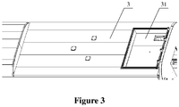
- a groove 31 is provided on the flat roof structure 3, and the high-voltage box 4 is arranged in the groove 31.
- the high-voltage box 4 can have enough height, which is convenient to accommodate the high-voltage apparatus in the high-voltage box 4.
- the groove 31 is a sliding groove arranged on the roof of the train, and the problem of water leakage is effectively solved by embedding the high-voltage box 4 into the groove 31.
- the outer wall of the high-voltage box 4 hermetically contacts with a groove side wall of the groove 31. Through the above arrangement, the sealing effect is effectively ensured.
- the outer wall of the high-voltage box 4 may merely be in surface contact with the side wall of the groove 31, and the sealing member may also be arranged therebetween.
- the flat roof structure 3 is an aluminum alloy structure. Through the above arrangement, the strength and corrosion resistance of the flat roof structure 3 are effectively improved, and the service life is effectively prolonged.
- a motor train unit is further provided according to the embodiment of the present application, which includes a pantograph platform structure.
- the pantograph platform structure is the pantograph platform structure as described above. Since the above pantograph platform structure has the above technical effect, the motor train unit having the above pantograph platform structure also has the same technical effect, which will not be described here.
Landscapes
- Engineering & Computer Science (AREA)
- Power Engineering (AREA)
- Transportation (AREA)
- Mechanical Engineering (AREA)
- Current-Collector Devices For Electrically Propelled Vehicles (AREA)
Abstract
Description
- This application claims the priority to Chinese Patent Application No.
201910142021.X - This application claims the priority to Chinese Patent Application No.
201920243939.9 - The present application relates to the technical field of railway transportation equipment, and particularly to a motor train unit and a pantograph platform structure thereof.
- With the development of high-speed motor train units, people pay their attention on how to reduce the aerodynamic noise and the aerodynamic resistance at the pantograph of the high-speed motor train unit.
- Many high-voltage components are provided on the flat roof of the conventional high-speed motor train unit. The exposure of the high-voltage components increases the aerodynamic noise and the aerodynamic resistance of the train. A few developed countries also use the high-voltage integration technology, but the train body structure is too complex and the installation is not convenient.
- The problems of the pantograph platform of the conventional high-speed motor train unit are as follows: (1) the high-voltage components are accommodated independently on the flat roof, which is easy to cause fog flashover of the high-voltage components, and increases the aerodynamic noise and the aerodynamic resistance of the upper portion of the train; (2) a guide guard is provided around the high-voltage components, the guide guard has limited capability to reduce resistance and noise, and the shape of the guide guard needs to be optimized; (3) the size of the pantograph area protruding from the train body is too large, which affects the aerodynamic performance of the whole train.
- Therefore, those skilled in the art have a strong desire to reduce the aerodynamic noise and the aerodynamic resistance and to improve the aerodynamic performance.
- In view of this, a pantograph platform structure is provided according to the present application, so as to reduce the aerodynamic noise and the aerodynamic resistance and to improve the aerodynamic performance. A motor train unit is further disclosed according to the present application.
- To achieve the above objects, the following technical solutions are provided according to the present application.
- As can be seen from the above technical solutions, the pantograph platform structure according to the present application includes:
- a train body structure having a sunken flat roof structure;
- a high-voltage box provided on the flat roof structure and configured to accommodate a high-voltage electrical apparatus, where, the high-voltage box is accommodated on the flat roof structure, and a top surface contour of the high-voltage box is aligned with a top surface outer contour of the train body structure; and
- a pantograph guide guard provided on the flat roof structure, where, the pantograph guide guard has an avoidance portion for installing a pantograph, the pantograph guide guard is accommodated on the flat roof structure, and a top surface contour of the guide guard is aligned with the top surface outer contour of the train body structure.
- Preferably, in the pantograph platform structure, the high-voltage box is located in the avoidance portion of the pantograph guide guard.
- Preferably, in the pantograph platform structure, the pantograph guide guard is a frame structure, and the avoidance portion is a hollow portion located in the middle of the frame structure.
- Preferably, in the pantograph platform structure, the high-voltage box hermetically contacts with an inner wall of the frame structure.
- Preferably, in the pantograph platform structure, the flat roof structure is provided with a groove; and
the high-voltage box is arranged in the groove. - Preferably, in the pantograph platform structure, an outer wall of the high-voltage box hermetically contacts with a side wall of the groove.
- Preferably, in the pantograph platform structure, the flat roof structure is an aluminum alloy structure.
- A motor train unit is further provided according to the embodiment of the present application, which includes a pantograph platform structure. The pantograph platform structure is the pantograph platform structure described in any one of the above.
- According to the pantograph platform structure provided by the present application, a sunken flat roof structure is arranged on the train body structure, and the pantograph guide guard and the high-voltage box are accommodated on the flat roof structure, the top surface contours of the pantograph guide guard and the high-voltage box are aligned with the top surface outer contour of the train body structure, so that the pantograph guide guard and the high-voltage box form the same structure as the top surface outer contour (non-flat roof structure) of the train body structure after installation. Since the high-voltage box is directly accommodated on the flat roof structure, the installation and maintenance of the high-voltage box are convenient. The high-voltage electrical apparatus is accommodated in the high-voltage box, which solves the problem of the fog flashover of the high-voltage components, and reduces the aerodynamic resistance and the aerodynamic noise. The top surface contours of the pantograph guide guard and the high-voltage box are aligned with the top surface outer contour of the train body structure, which effectively improves the aerodynamic performance.
- A motor train unit is further provided according to the present application. Since the motor train unit has the above pantograph platform structure, the above motor train unit has the same technical effect as the pantograph platform structure, which will not be described in detail here.
- To illustrate technical schemes according to the embodiments of the present application or in the conventional technology more clearly, the drawings to be used in the description of the conventional technology or the embodiments are described briefly hereinafter. Apparently, the drawings described hereinafter are only some embodiments of the present application, and other drawings may be obtained by those skilled in the art based on those drawings without creative effort.
-
Figure 1 is a schematic view showing the structure of a pantograph platform structure according to an embodiment of the present application; -
Figure 2 is a schematic view showing the structure of a high-voltage box according to the embodiment of the present application; -
Figure 3 is a schematic view showing the structure of a flat roof structure according to the embodiment of the present application; and -
Figure 4 is a schematic view showing the structure of a pantograph guide guard according to the embodiment of the present application. - A pantograph platform structure is disclosed according to the present application, so as to reduce the aerodynamic noise and the aerodynamic resistance and improve the aerodynamic performance. A motor train unit is further disclosed according to the present application.
- Technical solutions of embodiments of the present application are clearly and completely described hereinafter in conjunction with the drawings of the embodiments of the present application. Apparently, the embodiments described in the following are only some embodiments of the present application, rather than all embodiments. Any other embodiments obtained by those skilled in the art based on the embodiments in the present application without any creative work fall in the scope of protection of the present application.
- Referring to
Figures 1 and2 , the pantograph platform structure according to the embodiment of the present application includes: a train body structure having a sunkenflat roof structure 3; a high-voltage box 4 provided on theflat roof structure 3 and configured to accommodate a high-voltage electrical apparatus, where, the high-voltage box 4 is accommodated on theflat roof structure 3, and a top surface contour of the high-voltage box 4 is aligned with a top surface outer contour of the train body structure; and a pantograph guide guard 1 provided on theflat roof structure 3, where, the pantograph guide guard 1 has an avoidance portion for installing a pantograph, the pantograph guide guard 1 is accommodated on theflat roof structure 3, and a top surface contour of the guide guard 1 is aligned with the top surface outer contour of the train body structure. - According to the pantograph platform structure provided by the present application, the sunken
flat roof structure 3 is arranged on the train body structure, and the pantograph guide guard 1 and the high-voltage box 4 are accommodated on theflat roof structure 3. The top surface contours of the pantograph guide guard 1 and the high-voltage box 4 are aligned with the top surface outer contour of the train body structure, so that the pantograph guide guard 1 and the high-voltage box 4 form the same structure as the top surface outer contour (non-flat roof structure 3) of the train body structure after installation. Since the high-voltage box 4 is directly accommodated on theflat roof structure 3, the installation and maintenance of the high-voltage box 4 are convenient. The high-voltage electrical apparatus is accommodated in the high-voltage box 4, which solves the problem of the fog flashover of the high-voltage components, and reduces the aerodynamic resistance and the aerodynamic noise. The top surface contours of the pantograph guide guard 1 and the high-voltage box 4 are aligned with the top surface outer contour of the train body structure, which effectively improves the aerodynamic performance. - In order to improve the structural compactness and the stability of the high-
voltage box 4, the high-voltage box 4 is located in the avoidance portion of the pantograph guide guard 1. - In the present embodiment, the pantograph guide guard 1 is a frame structure, and the avoidance portion is a hollow portion located in the middle of the frame structure. Through the above arrangement, the processing of the pantograph guide guard 1 is effectively convenient, and the structural stability of the pantograph guide guard 1 is ensured.
- Furthermore, the high-
voltage box 4 hermetically contacts with an inner wall of the frame structure. Through the above arrangement, the protective effect of the pantograph guide guard 1 on the high-voltage box 4 is effectively ensured, so that the pantograph guide guard 1 ensures the rain-proof and snow-proof effect on the high-voltage box 4 on the basis of the guiding function. - The outer wall of the high-
voltage box 4 may merely be in surface contact with the inner wall of the frame structure, and a sealing member may also be provided therebetween. - In order to further improve the installation stability of the high-
voltage box 4, agroove 31 is provided on theflat roof structure 3, and the high-voltage box 4 is arranged in thegroove 31. Through the above arrangement, the high-voltage box 4 can have enough height, which is convenient to accommodate the high-voltage apparatus in the high-voltage box 4. - In an embodiment, the
groove 31 is a sliding groove arranged on the roof of the train, and the problem of water leakage is effectively solved by embedding the high-voltage box 4 into thegroove 31. - The outer wall of the high-
voltage box 4 hermetically contacts with a groove side wall of thegroove 31. Through the above arrangement, the sealing effect is effectively ensured. - The outer wall of the high-
voltage box 4 may merely be in surface contact with the side wall of thegroove 31, and the sealing member may also be arranged therebetween. - In order to improve the service life, the
flat roof structure 3 is an aluminum alloy structure. Through the above arrangement, the strength and corrosion resistance of theflat roof structure 3 are effectively improved, and the service life is effectively prolonged. - A motor train unit is further provided according to the embodiment of the present application, which includes a pantograph platform structure. The pantograph platform structure is the pantograph platform structure as described above. Since the above pantograph platform structure has the above technical effect, the motor train unit having the above pantograph platform structure also has the same technical effect, which will not be described here.
- The above embodiments are described in a progressive manner. Each of the embodiments is mainly focused on describing its differences from other embodiments, and references may be made among these embodiments with respect to the same or similar parts.
- The above illustration of the disclosed embodiments can enable those skilled in the art to practice or use the present application. Various modifications to the embodiments are apparent to the person skilled in the art, and the general principle herein can be implemented in other embodiments without departing from the spirit or scope of the present application. Therefore, the present disclosure is not limited to the embodiments described herein, but should be in accordance with the broadest scope consistent with the principle and novel features disclosed herein.
| 1 | pantograph guide guard, | 2 | pantograph, |
| 3 | flat roof structure, | 4 | high-voltage box |
Claims (8)
- A pantograph platform structure, comprising:a train body structure having a sunken flat roof structure (3);a high-voltage box (4) provided on the flat roof structure (3) and configured to accommodate a high-voltage electrical apparatus, wherein, the high-voltage box (4) is accommodated on the flat roof structure (3), and a top surface contour of the high-voltage box (4) is aligned with a top surface outer contour of the train body structure; anda pantograph guide guard (1) provided on the flat roof structure (3), wherein, the pantograph guide guard (1) has an avoidance portion for installing a pantograph, the pantograph guide guard (1) is accommodated on the flat roof structure (3), and a top surface contour of the guide guard (1) is aligned with the top surface outer contour of the train body structure.
- The pantograph platform structure according to claim 1, wherein the high-voltage box (4) is located in the avoidance portion of the pantograph guide guard (1).
- The pantograph platform structure according to claim 1, wherein, the pantograph guide guard (1) is a frame structure, and the avoidance portion is a hollow portion located in a middle of the frame structure.
- The pantograph platform structure according to claim 3, wherein the high-voltage box (4) hermetically contacts with an inner wall of the frame structure.
- The pantograph platform structure according to claim 1, wherein, the flat roof structure (3) is provided with a groove (31); and
the high-voltage box (4) is arranged in the groove (31). - The pantograph platform structure according to claim 5, wherein an outer wall of the high-voltage box (4) hermetically contacts with a side wall of the groove (31).
- The pantograph platform structure according to any one of claims 1 to 6, wherein, the flat roof structure (3) is an aluminum alloy structure.
- A motor train unit, comprising a pantograph platform structure, wherein the pantograph platform structure is the pantograph platform structure according to any one of claims 1 to 7.
Applications Claiming Priority (3)
| Application Number | Priority Date | Filing Date | Title |
|---|---|---|---|
| CN201910142021.XA CN109649177A (en) | 2019-02-26 | 2019-02-26 | EMU and its pantograph platform structure |
| CN201920243939.9U CN209700407U (en) | 2019-02-26 | 2019-02-26 | EMU and its pantograph platform structure |
| PCT/CN2020/076620 WO2020173435A1 (en) | 2019-02-26 | 2020-02-25 | Multiple-unit train and pantograph platform structure thereof |
Publications (2)
| Publication Number | Publication Date |
|---|---|
| EP3744558A1 true EP3744558A1 (en) | 2020-12-02 |
| EP3744558A4 EP3744558A4 (en) | 2021-11-10 |
Family
ID=72239109
Family Applications (1)
| Application Number | Title | Priority Date | Filing Date |
|---|---|---|---|
| EP20757509.3A Withdrawn EP3744558A4 (en) | 2019-02-26 | 2020-02-25 | Multiple-unit train and pantograph platform structure thereof |
Country Status (3)
| Country | Link |
|---|---|
| EP (1) | EP3744558A4 (en) |
| SG (1) | SG11202008009YA (en) |
| WO (1) | WO2020173435A1 (en) |
Family Cites Families (11)
| Publication number | Priority date | Publication date | Assignee | Title |
|---|---|---|---|---|
| JPH07193905A (en) * | 1993-12-27 | 1995-07-28 | Hitachi Ltd | Current collector for vehicle |
| JPH089505A (en) * | 1994-06-22 | 1996-01-12 | Railway Technical Res Inst | pantograph |
| JP3104199B2 (en) * | 1995-12-25 | 2000-10-30 | 東洋電機製造株式会社 | Collector boat for current collectors for railway vehicles |
| FR2955304B1 (en) * | 2010-01-19 | 2014-06-20 | Alstom Transport Sa | RAILWAY VEHICLE AND METHOD FOR MANUFACTURING THE SAME |
| WO2016141726A1 (en) * | 2015-03-12 | 2016-09-15 | 中车青岛四方机车车辆股份有限公司 | Rail vehicle and roof thereof |
| CN104709093B (en) * | 2015-03-12 | 2017-01-11 | 中车青岛四方机车车辆股份有限公司 | Pantograph installation seat of railway vehicle |
| JP2017169411A (en) * | 2016-03-18 | 2017-09-21 | 東日本旅客鉄道株式会社 | Current collector |
| CN206012355U (en) * | 2016-08-30 | 2017-03-15 | 青岛罗美威奥新材料制造有限公司 | A kind of nonmetallic kuppe of high-speed railway roof pantograph |
| CN109131389A (en) * | 2018-09-14 | 2019-01-04 | 中车青岛四方机车车辆股份有限公司 | A kind of roof structure of rail vehicle |
| CN209700407U (en) * | 2019-02-26 | 2019-11-29 | 中车长春轨道客车股份有限公司 | EMU and its pantograph platform structure |
| CN109649177A (en) * | 2019-02-26 | 2019-04-19 | 中车长春轨道客车股份有限公司 | EMU and its pantograph platform structure |
-
2020
- 2020-02-25 EP EP20757509.3A patent/EP3744558A4/en not_active Withdrawn
- 2020-02-25 WO PCT/CN2020/076620 patent/WO2020173435A1/en not_active Ceased
- 2020-02-25 SG SG11202008009YA patent/SG11202008009YA/en unknown
Also Published As
| Publication number | Publication date |
|---|---|
| EP3744558A4 (en) | 2021-11-10 |
| WO2020173435A1 (en) | 2020-09-03 |
| SG11202008009YA (en) | 2020-10-29 |
Similar Documents
| Publication | Publication Date | Title |
|---|---|---|
| IT8223153V0 (en) | LARGE PASSENGER SHIP, SUITABLE FOR CRUISES, INCLUDING AN LOWER PART FORMED BY THE HULL WITH COMMON SERVICES, AND A UPPER PART WITH ALL EXTERNAL CABINS. | |
| CN109649177A (en) | EMU and its pantograph platform structure | |
| CN209700407U (en) | EMU and its pantograph platform structure | |
| US20240268553A1 (en) | Outdoor cabinet | |
| CN210201124U (en) | Safe sliding contact line | |
| EP3968747A1 (en) | Drawer-type module sealing structure of inverter | |
| CN205828100U (en) | Dry-type transformer in a kind of wind power generator cabin | |
| CN210092488U (en) | High-voltage line external shield grounding structure | |
| CN213094083U (en) | Photovoltaic inverter protection device for photovoltaic power station | |
| CN208522272U (en) | A kind of switchgear and its cabinet body | |
| CN216928125U (en) | Improved solar photovoltaic wire | |
| CN110211775A (en) | Mobile box type transformer | |
| CN212907361U (en) | Dry-type transformer with unequal heights of high-voltage coil and low-voltage coil | |
| CN209982309U (en) | High-speed clean type linear electric motor module | |
| CN210715841U (en) | High-stability camshaft | |
| CN210787762U (en) | Wet-type electrostatic precipitator negative pole line lower part stop device | |
| CN210272035U (en) | Resin pouring dry-type transformer increases creepage distance's cushion structure | |
| CN224082266U (en) | Lightning protection glass insulator | |
| CN207328626U (en) | A kind of new automobile sill plate | |
| CN215553231U (en) | Dispatching vehicle-mounted platform terminal MMI | |
| CN208241365U (en) | Mobile energy storage safety power supply System cabine | |
| CN206255002U (en) | For the accommodating storehouse of high voltage component and EMU | |
| CN216598508U (en) | Building electrical construction safety device | |
| CN206098120U (en) | Reactor skeleton | |
| CN2534663Y (en) | Dry type current mutual inductor |
Legal Events
| Date | Code | Title | Description |
|---|---|---|---|
| STAA | Information on the status of an ep patent application or granted ep patent |
Free format text: STATUS: UNKNOWN |
|
| STAA | Information on the status of an ep patent application or granted ep patent |
Free format text: STATUS: THE INTERNATIONAL PUBLICATION HAS BEEN MADE |
|
| PUAI | Public reference made under article 153(3) epc to a published international application that has entered the european phase |
Free format text: ORIGINAL CODE: 0009012 |
|
| STAA | Information on the status of an ep patent application or granted ep patent |
Free format text: STATUS: REQUEST FOR EXAMINATION WAS MADE |
|
| 17P | Request for examination filed |
Effective date: 20200826 |
|
| AK | Designated contracting states |
Kind code of ref document: A1 Designated state(s): AL AT BE BG CH CY CZ DE DK EE ES FI FR GB GR HR HU IE IS IT LI LT LU LV MC MK MT NL NO PL PT RO RS SE SI SK SM TR |
|
| AX | Request for extension of the european patent |
Extension state: BA ME |
|
| A4 | Supplementary search report drawn up and despatched |
Effective date: 20211012 |
|
| RIC1 | Information provided on ipc code assigned before grant |
Ipc: B60L 5/18 20060101ALI20211006BHEP Ipc: B60L 5/20 20060101AFI20211006BHEP |
|
| DAV | Request for validation of the european patent (deleted) | ||
| DAX | Request for extension of the european patent (deleted) | ||
| STAA | Information on the status of an ep patent application or granted ep patent |
Free format text: STATUS: THE APPLICATION IS DEEMED TO BE WITHDRAWN |
|
| 18D | Application deemed to be withdrawn |
Effective date: 20220510 |