EP3744443A1 - Exhaust manifold for additive manufacturing - Google Patents
Exhaust manifold for additive manufacturing Download PDFInfo
- Publication number
- EP3744443A1 EP3744443A1 EP19211154.0A EP19211154A EP3744443A1 EP 3744443 A1 EP3744443 A1 EP 3744443A1 EP 19211154 A EP19211154 A EP 19211154A EP 3744443 A1 EP3744443 A1 EP 3744443A1
- Authority
- EP
- European Patent Office
- Prior art keywords
- manifold
- housing
- baffles
- baffle
- actuator
- Prior art date
- Legal status (The legal status is an assumption and is not a legal conclusion. Google has not performed a legal analysis and makes no representation as to the accuracy of the status listed.)
- Granted
Links
Images



Classifications
-
- F—MECHANICAL ENGINEERING; LIGHTING; HEATING; WEAPONS; BLASTING
- F24—HEATING; RANGES; VENTILATING
- F24F—AIR-CONDITIONING; AIR-HUMIDIFICATION; VENTILATION; USE OF AIR CURRENTS FOR SCREENING
- F24F13/00—Details common to, or for air-conditioning, air-humidification, ventilation or use of air currents for screening
- F24F13/08—Air-flow control members, e.g. louvres, grilles, flaps or guide plates
- F24F13/10—Air-flow control members, e.g. louvres, grilles, flaps or guide plates movable, e.g. dampers
-
- B—PERFORMING OPERATIONS; TRANSPORTING
- B22—CASTING; POWDER METALLURGY
- B22F—WORKING METALLIC POWDER; MANUFACTURE OF ARTICLES FROM METALLIC POWDER; MAKING METALLIC POWDER; APPARATUS OR DEVICES SPECIALLY ADAPTED FOR METALLIC POWDER
- B22F10/00—Additive manufacturing of workpieces or articles from metallic powder
- B22F10/20—Direct sintering or melting
- B22F10/28—Powder bed fusion, e.g. selective laser melting [SLM] or electron beam melting [EBM]
-
- B—PERFORMING OPERATIONS; TRANSPORTING
- B22—CASTING; POWDER METALLURGY
- B22F—WORKING METALLIC POWDER; MANUFACTURE OF ARTICLES FROM METALLIC POWDER; MAKING METALLIC POWDER; APPARATUS OR DEVICES SPECIALLY ADAPTED FOR METALLIC POWDER
- B22F10/00—Additive manufacturing of workpieces or articles from metallic powder
- B22F10/30—Process control
- B22F10/32—Process control of the atmosphere, e.g. composition or pressure in a building chamber
- B22F10/322—Process control of the atmosphere, e.g. composition or pressure in a building chamber of the gas flow, e.g. rate or direction
-
- B—PERFORMING OPERATIONS; TRANSPORTING
- B22—CASTING; POWDER METALLURGY
- B22F—WORKING METALLIC POWDER; MANUFACTURE OF ARTICLES FROM METALLIC POWDER; MAKING METALLIC POWDER; APPARATUS OR DEVICES SPECIALLY ADAPTED FOR METALLIC POWDER
- B22F12/00—Apparatus or devices specially adapted for additive manufacturing; Auxiliary means for additive manufacturing; Combinations of additive manufacturing apparatus or devices with other processing apparatus or devices
- B22F12/70—Gas flow means
-
- B—PERFORMING OPERATIONS; TRANSPORTING
- B23—MACHINE TOOLS; METAL-WORKING NOT OTHERWISE PROVIDED FOR
- B23K—SOLDERING OR UNSOLDERING; WELDING; CLADDING OR PLATING BY SOLDERING OR WELDING; CUTTING BY APPLYING HEAT LOCALLY, e.g. FLAME CUTTING; WORKING BY LASER BEAM
- B23K26/00—Working by laser beam, e.g. welding, cutting or boring
- B23K26/12—Working by laser beam, e.g. welding, cutting or boring in a special environment or atmosphere, e.g. in an enclosure
- B23K26/127—Working by laser beam, e.g. welding, cutting or boring in a special environment or atmosphere, e.g. in an enclosure in an enclosure
-
- B—PERFORMING OPERATIONS; TRANSPORTING
- B23—MACHINE TOOLS; METAL-WORKING NOT OTHERWISE PROVIDED FOR
- B23K—SOLDERING OR UNSOLDERING; WELDING; CLADDING OR PLATING BY SOLDERING OR WELDING; CUTTING BY APPLYING HEAT LOCALLY, e.g. FLAME CUTTING; WORKING BY LASER BEAM
- B23K26/00—Working by laser beam, e.g. welding, cutting or boring
- B23K26/14—Working by laser beam, e.g. welding, cutting or boring using a fluid stream, e.g. a jet of gas, in conjunction with the laser beam; Nozzles therefor
- B23K26/142—Working by laser beam, e.g. welding, cutting or boring using a fluid stream, e.g. a jet of gas, in conjunction with the laser beam; Nozzles therefor for the removal of by-products
-
- B—PERFORMING OPERATIONS; TRANSPORTING
- B23—MACHINE TOOLS; METAL-WORKING NOT OTHERWISE PROVIDED FOR
- B23K—SOLDERING OR UNSOLDERING; WELDING; CLADDING OR PLATING BY SOLDERING OR WELDING; CUTTING BY APPLYING HEAT LOCALLY, e.g. FLAME CUTTING; WORKING BY LASER BEAM
- B23K26/00—Working by laser beam, e.g. welding, cutting or boring
- B23K26/14—Working by laser beam, e.g. welding, cutting or boring using a fluid stream, e.g. a jet of gas, in conjunction with the laser beam; Nozzles therefor
- B23K26/1435—Working by laser beam, e.g. welding, cutting or boring using a fluid stream, e.g. a jet of gas, in conjunction with the laser beam; Nozzles therefor involving specially adapted flow-control means
- B23K26/1437—Working by laser beam, e.g. welding, cutting or boring using a fluid stream, e.g. a jet of gas, in conjunction with the laser beam; Nozzles therefor involving specially adapted flow-control means for flow-rate control
-
- B—PERFORMING OPERATIONS; TRANSPORTING
- B23—MACHINE TOOLS; METAL-WORKING NOT OTHERWISE PROVIDED FOR
- B23K—SOLDERING OR UNSOLDERING; WELDING; CLADDING OR PLATING BY SOLDERING OR WELDING; CUTTING BY APPLYING HEAT LOCALLY, e.g. FLAME CUTTING; WORKING BY LASER BEAM
- B23K26/00—Working by laser beam, e.g. welding, cutting or boring
- B23K26/14—Working by laser beam, e.g. welding, cutting or boring using a fluid stream, e.g. a jet of gas, in conjunction with the laser beam; Nozzles therefor
- B23K26/1435—Working by laser beam, e.g. welding, cutting or boring using a fluid stream, e.g. a jet of gas, in conjunction with the laser beam; Nozzles therefor involving specially adapted flow-control means
- B23K26/1438—Working by laser beam, e.g. welding, cutting or boring using a fluid stream, e.g. a jet of gas, in conjunction with the laser beam; Nozzles therefor involving specially adapted flow-control means for directional control
-
- B—PERFORMING OPERATIONS; TRANSPORTING
- B23—MACHINE TOOLS; METAL-WORKING NOT OTHERWISE PROVIDED FOR
- B23K—SOLDERING OR UNSOLDERING; WELDING; CLADDING OR PLATING BY SOLDERING OR WELDING; CUTTING BY APPLYING HEAT LOCALLY, e.g. FLAME CUTTING; WORKING BY LASER BEAM
- B23K26/00—Working by laser beam, e.g. welding, cutting or boring
- B23K26/34—Laser welding for purposes other than joining
- B23K26/342—Build-up welding
-
- B—PERFORMING OPERATIONS; TRANSPORTING
- B29—WORKING OF PLASTICS; WORKING OF SUBSTANCES IN A PLASTIC STATE IN GENERAL
- B29C—SHAPING OR JOINING OF PLASTICS; SHAPING OF MATERIAL IN A PLASTIC STATE, NOT OTHERWISE PROVIDED FOR; AFTER-TREATMENT OF THE SHAPED PRODUCTS, e.g. REPAIRING
- B29C64/00—Additive manufacturing, i.e. manufacturing of three-dimensional [3D] objects by additive deposition, additive agglomeration or additive layering, e.g. by 3D printing, stereolithography or selective laser sintering
- B29C64/30—Auxiliary operations or equipment
-
- B—PERFORMING OPERATIONS; TRANSPORTING
- B33—ADDITIVE MANUFACTURING TECHNOLOGY
- B33Y—ADDITIVE MANUFACTURING, i.e. MANUFACTURING OF THREE-DIMENSIONAL [3D] OBJECTS BY ADDITIVE DEPOSITION, ADDITIVE AGGLOMERATION OR ADDITIVE LAYERING, e.g. BY 3D PRINTING, STEREOLITHOGRAPHY OR SELECTIVE LASER SINTERING
- B33Y10/00—Processes of additive manufacturing
-
- B—PERFORMING OPERATIONS; TRANSPORTING
- B33—ADDITIVE MANUFACTURING TECHNOLOGY
- B33Y—ADDITIVE MANUFACTURING, i.e. MANUFACTURING OF THREE-DIMENSIONAL [3D] OBJECTS BY ADDITIVE DEPOSITION, ADDITIVE AGGLOMERATION OR ADDITIVE LAYERING, e.g. BY 3D PRINTING, STEREOLITHOGRAPHY OR SELECTIVE LASER SINTERING
- B33Y30/00—Apparatus for additive manufacturing; Details thereof or accessories therefor
-
- B—PERFORMING OPERATIONS; TRANSPORTING
- B33—ADDITIVE MANUFACTURING TECHNOLOGY
- B33Y—ADDITIVE MANUFACTURING, i.e. MANUFACTURING OF THREE-DIMENSIONAL [3D] OBJECTS BY ADDITIVE DEPOSITION, ADDITIVE AGGLOMERATION OR ADDITIVE LAYERING, e.g. BY 3D PRINTING, STEREOLITHOGRAPHY OR SELECTIVE LASER SINTERING
- B33Y40/00—Auxiliary operations or equipment, e.g. for material handling
-
- B—PERFORMING OPERATIONS; TRANSPORTING
- B22—CASTING; POWDER METALLURGY
- B22F—WORKING METALLIC POWDER; MANUFACTURE OF ARTICLES FROM METALLIC POWDER; MAKING METALLIC POWDER; APPARATUS OR DEVICES SPECIALLY ADAPTED FOR METALLIC POWDER
- B22F12/00—Apparatus or devices specially adapted for additive manufacturing; Auxiliary means for additive manufacturing; Combinations of additive manufacturing apparatus or devices with other processing apparatus or devices
- B22F12/90—Means for process control, e.g. cameras or sensors
-
- Y—GENERAL TAGGING OF NEW TECHNOLOGICAL DEVELOPMENTS; GENERAL TAGGING OF CROSS-SECTIONAL TECHNOLOGIES SPANNING OVER SEVERAL SECTIONS OF THE IPC; TECHNICAL SUBJECTS COVERED BY FORMER USPC CROSS-REFERENCE ART COLLECTIONS [XRACs] AND DIGESTS
- Y02—TECHNOLOGIES OR APPLICATIONS FOR MITIGATION OR ADAPTATION AGAINST CLIMATE CHANGE
- Y02P—CLIMATE CHANGE MITIGATION TECHNOLOGIES IN THE PRODUCTION OR PROCESSING OF GOODS
- Y02P10/00—Technologies related to metal processing
- Y02P10/25—Process efficiency
Definitions
- This disclosure relates to additive manufacturing, more specifically to exhaust manifolds for additive manufacturing.
- Additive manufacturing laser powder bed systems use gas flow in the build volume to improve build quality.
- the gas flow occurs above the build plate and is intended to push gas discharge away from the melt pool and prevent laser interference.
- gas flow from the nozzle to the exhaust manifold is not constant. The gas flow varies across the length of the gas nozzle. Poor flow distribution leads to "keep out" areas on the build plate where a user avoids building due to poor flow. Further, uneven gas flow results in reduction of build quality.
- an exhaust manifold for an additive manufacturing system can include a manifold housing, at least one baffle movable relative to the manifold housing configured to modify an exhaust flow area defined in part by the at least one baffle, and an actuator operatively connected to the at least one baffle configured to move the at least one baffle.
- the manifold housing can define a housing channel.
- the at least one baffle can be one or more moveable baffles at least partially disposed within the housing channel and configured to move relative to the housing to modify a respective exhaust flow area of a respective baffle of the one or more moveable baffles.
- the actuator can be operatively connected to each of the one or more movable baffles and configured to move the one or more movable baffles relative to the housing.
- the one or more moveable baffles can include a plurality of moveable baffles configured to move relative to the housing and relative to each other to modify a respective exhaust flow area.
- Each of the plurality of baffles can include an L-shape, or any other suitable shape.
- Each movable baffle can be positioned in overlapping series with each other such that each respective exhaust flow area is defined between adjacent baffles.
- Each moveable baffle can include a different shape and/or size compared to an adjacent baffle to fit each moveable baffle within the manifold housing.
- the manifold can include a controller configured to control each actuator as a function of data from a flow field sensor in the additive manufacturing system.
- the controller can include any suitable hardware and/or software module(s) as appreciated by those having ordinary skill in the art.
- Each actuator can include a worm gear or any other suitable type of actuator (e.g., a stepper motor).
- Each actuator can be mounted to an outside surface of the manifold housing, for example, or in any other suitable location.
- the one or more moveable baffles can be connected to each actuator through a slot in the manifold housing.
- an additive manufacturing sweep flow system can include a flow source (e.g., an inlet manifold) and an exhaust manifold.
- the exhaust manifold can be any suitable embodiment as disclosed herein (e.g., as described above).
- the system can include a flow field sensor and a controller configured to control each actuator as a function of data from the flow field sensor in the additive manufacturing system.
- a method can include modifying an exhaust flow area in a portion of an exhaust manifold to control flow distribution over a build plate of an additive manufacturing system.
- Controlling flow distribution can include modifying a flow field, for example. Any other suitable methods and/or portions thereof are contemplated herein.
- FIG. 1 an illustrative view of an embodiment of an exhaust manifold in accordance with the disclosure is shown in Fig. 1 and is designated generally by reference character 100.
- FIG. 2-7 Other embodiments and/or aspects of this disclosure are shown in Figs. 2-7 .
- Certain embodiments described herein can be used to control a flow field over a build plate in an additive manufacturing system, for example.
- an exhaust manifold 100 for an additive manufacturing system can include a manifold housing 101, at least one baffle 109a, b, c, d, e movable relative to the manifold housing 101 and configured to modify an exhaust flow area defined in part by the at least one baffle 109a, b, c, d ,e, and an actuator 113a, b, c, d, e operatively connected to the at least one baffle 109a, b, c, d, e and configured to move the at least one baffle 109a, b, c, d, e.
- the manifold housing 101 can define a housing channel 103.
- the housing 101 can define an inlet opening 105 (e.g., defined along a long axis of the housing 101) and an outlet opening 107 (e.g., defined in an end of the housing 101) in fluid communication through the housing channel 103.
- the at least one baffle 109a, b, c, d, e can include one or more moveable baffles 109a, b, c, d, e, at least partially disposed within the housing channel 103 and configured to move relative to the housing 101 to modify a respective exhaust flow area 111a, b, c, d, e, f of a respective baffle of the one or more moveable baffles 109a, b, c, d, e, for example, as shown.
- the manifold 100 can include an actuator 113a, b, c, d, e can be operatively connected to each of the one or more movable baffles 109a, b, c, d, e.
- Each actuator 113a, b, c, d, e can be configured to move the one or more movable baffles 109a, b, c, d, e relative to the housing 101.
- the one or more baffles 109a, b, c, d, e can be disposed in a linear track (e.g., resting on the housing and/or including bearings) in the housing 101 to fix the one or more baffles 109a, b, c, d, e to sliding motion in 1 axis, for example.
- a linear track e.g., resting on the housing and/or including bearings
- Any other suitable configuration for controlling the motion of the one or more baffles 109a, b, c, d, e is contemplated herein.
- Each actuator 113a, b, c, d, e can include a worm gear or any other suitable type of actuator (e.g., a stepper motor, any other suitable linear motor and/or assembly).
- Each actuator 113a, b, c, d, e can be mounted to an outside surface of the manifold housing 101 (e.g., as shown), for example, or in any other suitable location.
- the one or more moveable baffles 109a, b, c, d, e can be connected to each actuator through a slot (shown covered by an arm of each actuator) in the manifold housing 101.
- the one or more moveable baffles 109a, b, c, d, e can include a plurality of moveable baffles 109a, b, c, d, e, for example, as shown.
- the plurality of baffles 109a, b, c, d, e can be configured to move relative to the housing 101 and relative to each other to modify a respective exhaust flow area 111a, b, c, d, e, f for example.
- Each of the plurality of baffles 109a, b, c, d, e can include an L-shape, e.g., as shown, or any other suitable shape. The L-shape can act to redirect flow to the outlet 107.
- the one or more baffles 109a, b, c, d, e can be made of sheet metal or any other suitable material, for example (e.g., plastic, ceramic).
- each movable baffle 109a, b, c, d, e can be positioned in overlapping series with each other such that each respective exhaust flow area 111a, b, c, d can be defined between adjacent baffles (e.g., as shown between 109a and 109b).
- Each moveable baffle 109a, b, c, d, e can include a different shape and/or size compared to an adjacent baffle to fit each moveable baffle 109a, b, c, d, e within the manifold housing 101 in the overlapping series.
- the manifold 100 can include a controller 315 configured to control each actuator 113a, b, c, d, e as a function of data from a flow field sensor 117 in the additive manufacturing system (e.g., as shown in Figs. 5 and 7 ).
- the controller 115 can be configured to enlarge one or more flow areas 111a, b, c, d, e, f if a respective portion of a flow field is relatively low flow compared to another portion of the flow field.
- the controller 115 can include any suitable hardware and/or software module(s) as appreciated by those having ordinary skill in the art.
- the controller 315 can be integrated with (e.g., attached to) or separate from the housing 101, for example.
- an additive manufacturing sweep flow system 500 can include a flow source 519 (e.g., an inlet manifold) and an exhaust manifold 100.
- the exhaust manifold 100 can be any suitable embodiment as disclosed herein (e.g., as described above).
- the system 500 can include a flow field sensor 117 and a controller 115 configured to control each actuator 113a, b, c, d, e as a function of data from the flow field sensor 117 in the additive manufacturing system 500.
- the flow field sensor 117 can include any suitable device positioned in any suitable location in the system 500.
- the flow field sensor 117 can include a series of pressure taps on an airfoil limb to determine flow speed in at least a portion of the flow field (e.g., one pressure tap per baffle in a corresponding location).
- Fig. 4 shows baffles 109a, b, c, d, e in a first state (e.g., baffles 109a, b, c, d, e have approximately equivalent exhaust flow areas 111a, b, c, d, e, f) resulting in an uneven flow field.
- Fig. 5 shows an uneven flow field traversing a build area corresponding to the state shown in Fig. 4 .
- Fig. 6 shows the baffles 109a, b, c, d, e in a second state (e.g., where baffle 109a is moved backward to open the exhaust flow area 111a which is shown as larger than in Figs.
- FIG. 7 shows the even flow field traversing a build area corresponding to the state shown in Fig. 6 .
- the size and/length of the arrows indicates a flow strength, such that a larger or longer arrow indicates more or faster flow.
- a method can include modifying an exhaust flow area in a portion of an exhaust manifold to control flow distribution over a build plate (e.g., build plate 599 as shown in Figs. 5 and 7 ) of an additive manufacturing system.
- Controlling flow distribution can include modifying a flow field, for example. Any other suitable methods and/or portions thereof are contemplated herein. Any suitable method herein can be performed by any suitable computer hardware and/or software as appreciated by those having ordinary skill in the art in view of this disclosure.
- Embodiments can be a drop in replacement for existing exhaust manifolds of additive manufacturing systems. Embodiments can allow changing of position of baffles to control the flow field over the build plate to create uniform and consistent flow field and to eliminate "keep out zones.”
- Certain embodiments can be controlled manually. For example, in certain embodiments, an operator can monitor sweeping gas and change a position of the one or more baffles when it is not flowing properly.
- Embodiments include a variable baffle exhaust manifold that can address existing issues with additive manufacturing systems.
- embodiments can include a sequence of baffles can be actuated by linear drives, for example, and can be stabilized by linear bearings (not shown) to allow the baffles to move along the axis of the linear drive.
- Embodiments can increase or decrease the spacing (e.g., the cross sectional outlet area of the baffles) between the baffles which can affect the flow distribution. This can enable the baffles to be controlled as a function of the gas flow from the flow source (e.g., the gas nozzle). This allows mitigation of irregular gas flow affects which are present in additive manufacturing build systems.
- Embodiments can include flow sensors mounted in the gas nozzle or the build plate area and can result in a real-time and/or adaptive control system for the exhaust manifold.
- a constant gas flow in the build chamber improves build quality of the part. Less variation in the operating conditions leads to a more predictable build with fewer internal defects.
- any numerical values disclosed herein can be exact values or can be values within a range. Further, any terms of approximation (e.g., “about”, “approximately”, “around”) used in this disclosure can mean the stated value within a range. For example, in certain embodiments, the range can be within (plus or minus) 20%, or within 10%, or within 5%, or within 2%, or within any other suitable percentage or number as appreciated by those having ordinary skill in the art (e.g., for known tolerance limits or error ranges).
Landscapes
- Engineering & Computer Science (AREA)
- Physics & Mathematics (AREA)
- Optics & Photonics (AREA)
- Chemical & Material Sciences (AREA)
- Manufacturing & Machinery (AREA)
- Materials Engineering (AREA)
- Mechanical Engineering (AREA)
- Plasma & Fusion (AREA)
- Automation & Control Theory (AREA)
- Combustion & Propulsion (AREA)
- General Engineering & Computer Science (AREA)
- Fluid Mechanics (AREA)
- Exhaust Silencers (AREA)
Abstract
Description
- This disclosure relates to additive manufacturing, more specifically to exhaust manifolds for additive manufacturing.
- Additive manufacturing laser powder bed systems use gas flow in the build volume to improve build quality. The gas flow occurs above the build plate and is intended to push gas discharge away from the melt pool and prevent laser interference. In traditional systems, gas flow from the nozzle to the exhaust manifold is not constant. The gas flow varies across the length of the gas nozzle. Poor flow distribution leads to "keep out" areas on the build plate where a user avoids building due to poor flow. Further, uneven gas flow results in reduction of build quality.
- Such conventional methods and systems have generally been considered satisfactory for their intended purpose. However, there is still a need in the art for improved gas flow systems and components. The present disclosure provides a solution for this need.
- In accordance with at least one aspect of this disclosure, an exhaust manifold for an additive manufacturing system can include a manifold housing, at least one baffle movable relative to the manifold housing configured to modify an exhaust flow area defined in part by the at least one baffle, and an actuator operatively connected to the at least one baffle configured to move the at least one baffle. The manifold housing can define a housing channel. The at least one baffle can be one or more moveable baffles at least partially disposed within the housing channel and configured to move relative to the housing to modify a respective exhaust flow area of a respective baffle of the one or more moveable baffles. The actuator can be operatively connected to each of the one or more movable baffles and configured to move the one or more movable baffles relative to the housing.
- The one or more moveable baffles can include a plurality of moveable baffles configured to move relative to the housing and relative to each other to modify a respective exhaust flow area. Each of the plurality of baffles can include an L-shape, or any other suitable shape.
- Each movable baffle can be positioned in overlapping series with each other such that each respective exhaust flow area is defined between adjacent baffles. Each moveable baffle can include a different shape and/or size compared to an adjacent baffle to fit each moveable baffle within the manifold housing.
- In certain embodiments, the manifold can include a controller configured to control each actuator as a function of data from a flow field sensor in the additive manufacturing system. The controller can include any suitable hardware and/or software module(s) as appreciated by those having ordinary skill in the art.
- Each actuator can include a worm gear or any other suitable type of actuator (e.g., a stepper motor). Each actuator can be mounted to an outside surface of the manifold housing, for example, or in any other suitable location. In certain embodiments, the one or more moveable baffles can be connected to each actuator through a slot in the manifold housing.
- In accordance with at least one aspect of this disclosure, an additive manufacturing sweep flow system can include a flow source (e.g., an inlet manifold) and an exhaust manifold. The exhaust manifold can be any suitable embodiment as disclosed herein (e.g., as described above). In certain embodiments, the system can include a flow field sensor and a controller configured to control each actuator as a function of data from the flow field sensor in the additive manufacturing system.
- In accordance with at least one aspect of this disclosure, a method can include modifying an exhaust flow area in a portion of an exhaust manifold to control flow distribution over a build plate of an additive manufacturing system. Controlling flow distribution can include modifying a flow field, for example. Any other suitable methods and/or portions thereof are contemplated herein.
- These and other features of the embodiments of the subject disclosure will become more readily apparent to those skilled in the art from the following detailed description taken in conjunction with the drawings.
- So that those skilled in the art to which the subject disclosure appertains will readily understand how to make and use the devices and methods of the subject disclosure without undue experimentation, embodiments thereof will be described in detail herein below, by way of background only and with reference to certain figures, wherein:
-
Fig. 1 is a perspective view of an embodiment of an exhaust manifold in accordance with this disclosure; -
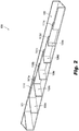
Fig. 2 is a cut-away perspective view of the embodiment ofFig. 1 ; -
Fig. 3 is a perspective view of the embodiment ofFig. 1 , showing an embodiment of a controller operatively connected thereto; -
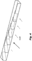
Fig. 4 is a cut-away perspective view of the embodiment ofFig. 1 , shown in a first state resulting in an uneven flow field; -
Fig. 5 is a schematic plan view of a system in accordance with this disclosure, showing an uneven flow field traversing a build area corresponding to the state of the embodiment ofFig. 4 . -
Fig. 6 is a partial cut-away perspective view of the embodiment ofFig. 1 , shown in a second state resulting in an even flow field; and -
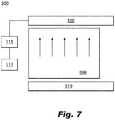
Fig. 7 is a schematic plan view of the system ofFig. 5 , showing an even flow field traversing a build area corresponding to the state of the embodiment ofFig. 6 . - Reference will now be made to the drawings wherein like reference numerals identify similar structural features or aspects of the subject disclosure. For purposes of explanation and illustration, and not limitation, an illustrative view of an embodiment of an exhaust manifold in accordance with the disclosure is shown in
Fig. 1 and is designated generally byreference character 100. Other embodiments and/or aspects of this disclosure are shown inFigs. 2-7 . Certain embodiments described herein can be used to control a flow field over a build plate in an additive manufacturing system, for example. - Referring to
Figs. 1 and2 , anexhaust manifold 100 for an additive manufacturing system can include amanifold housing 101, at least onebaffle 109a, b, c, d, e movable relative to themanifold housing 101 and configured to modify an exhaust flow area defined in part by the at least onebaffle 109a, b, c, d ,e, and anactuator 113a, b, c, d, e operatively connected to the at least onebaffle 109a, b, c, d, e and configured to move the at least onebaffle 109a, b, c, d, e. Themanifold housing 101 can define ahousing channel 103. Thehousing 101 can define an inlet opening 105 (e.g., defined along a long axis of the housing 101) and an outlet opening 107 (e.g., defined in an end of the housing 101) in fluid communication through thehousing channel 103. - The at least one
baffle 109a, b, c, d, e can include one or moremoveable baffles 109a, b, c, d, e, at least partially disposed within thehousing channel 103 and configured to move relative to thehousing 101 to modify a respectiveexhaust flow area 111a, b, c, d, e, f of a respective baffle of the one or moremoveable baffles 109a, b, c, d, e, for example, as shown. - The
manifold 100 can include anactuator 113a, b, c, d, e can be operatively connected to each of the one or moremovable baffles 109a, b, c, d, e. Eachactuator 113a, b, c, d, e can be configured to move the one or moremovable baffles 109a, b, c, d, e relative to thehousing 101. In certain embodiments, the one ormore baffles 109a, b, c, d, e can be disposed in a linear track (e.g., resting on the housing and/or including bearings) in thehousing 101 to fix the one ormore baffles 109a, b, c, d, e to sliding motion in 1 axis, for example. Any other suitable configuration for controlling the motion of the one ormore baffles 109a, b, c, d, e is contemplated herein. - Each
actuator 113a, b, c, d, e can include a worm gear or any other suitable type of actuator (e.g., a stepper motor, any other suitable linear motor and/or assembly). Eachactuator 113a, b, c, d, e can be mounted to an outside surface of the manifold housing 101 (e.g., as shown), for example, or in any other suitable location. In certain embodiments, the one or moremoveable baffles 109a, b, c, d, e can be connected to each actuator through a slot (shown covered by an arm of each actuator) in themanifold housing 101. - The one or more
moveable baffles 109a, b, c, d, e can include a plurality ofmoveable baffles 109a, b, c, d, e, for example, as shown. The plurality ofbaffles 109a, b, c, d, e can be configured to move relative to thehousing 101 and relative to each other to modify a respectiveexhaust flow area 111a, b, c, d, e, f for example. Each of the plurality ofbaffles 109a, b, c, d, e can include an L-shape, e.g., as shown, or any other suitable shape. The L-shape can act to redirect flow to theoutlet 107. The one ormore baffles 109a, b, c, d, e can be made of sheet metal or any other suitable material, for example (e.g., plastic, ceramic). - As shown in
Fig. 2 , eachmovable baffle 109a, b, c, d, e can be positioned in overlapping series with each other such that each respectiveexhaust flow area 111a, b, c, d can be defined between adjacent baffles (e.g., as shown between 109a and 109b). Eachmoveable baffle 109a, b, c, d, e can include a different shape and/or size compared to an adjacent baffle to fit eachmoveable baffle 109a, b, c, d, e within themanifold housing 101 in the overlapping series. - Referring additionally to
Fig. 3 , in certain embodiments, the manifold 100 can include acontroller 315 configured to control each actuator 113a, b, c, d, e as a function of data from aflow field sensor 117 in the additive manufacturing system (e.g., as shown inFigs. 5 and7 ). For example, thecontroller 115 can be configured to enlarge one ormore flow areas 111a, b, c, d, e, f if a respective portion of a flow field is relatively low flow compared to another portion of the flow field. Thecontroller 115 can include any suitable hardware and/or software module(s) as appreciated by those having ordinary skill in the art. Thecontroller 315 can be integrated with (e.g., attached to) or separate from thehousing 101, for example. - Referring additionally to
Figs. 4 ,5 ,6 , and7 , an additive manufacturingsweep flow system 500 can include a flow source 519 (e.g., an inlet manifold) and anexhaust manifold 100. Theexhaust manifold 100 can be any suitable embodiment as disclosed herein (e.g., as described above). In certain embodiments, thesystem 500 can include aflow field sensor 117 and acontroller 115 configured to control each actuator 113a, b, c, d, e as a function of data from theflow field sensor 117 in theadditive manufacturing system 500. - The
flow field sensor 117 can include any suitable device positioned in any suitable location in thesystem 500. For example, theflow field sensor 117 can include a series of pressure taps on an airfoil limb to determine flow speed in at least a portion of the flow field (e.g., one pressure tap per baffle in a corresponding location). -
Fig. 4 showsbaffles 109a, b, c, d, e in a first state (e.g., baffles 109a, b, c, d, e have approximately equivalentexhaust flow areas 111a, b, c, d, e, f) resulting in an uneven flow field.Fig. 5 shows an uneven flow field traversing a build area corresponding to the state shown inFig. 4 .Fig. 6 shows thebaffles 109a, b, c, d, e in a second state (e.g., wherebaffle 109a is moved backward to open theexhaust flow area 111a which is shown as larger than inFigs. 1-4 , and flowarea 111f is shown as smaller) resulting in an even flow field.Fig. 7 shows the even flow field traversing a build area corresponding to the state shown inFig. 6 . As show in theFigs. 4-7 , the size and/length of the arrows indicates a flow strength, such that a larger or longer arrow indicates more or faster flow. - In accordance with at least one aspect of this disclosure, a method can include modifying an exhaust flow area in a portion of an exhaust manifold to control flow distribution over a build plate (e.g., build
plate 599 as shown inFigs. 5 and7 ) of an additive manufacturing system. Controlling flow distribution can include modifying a flow field, for example. Any other suitable methods and/or portions thereof are contemplated herein. Any suitable method herein can be performed by any suitable computer hardware and/or software as appreciated by those having ordinary skill in the art in view of this disclosure. - Embodiments can be a drop in replacement for existing exhaust manifolds of additive manufacturing systems. Embodiments can allow changing of position of baffles to control the flow field over the build plate to create uniform and consistent flow field and to eliminate "keep out zones."
- Certain embodiments can be controlled manually. For example, in certain embodiments, an operator can monitor sweeping gas and change a position of the one or more baffles when it is not flowing properly.
- Embodiments include a variable baffle exhaust manifold that can address existing issues with additive manufacturing systems. As disclosed above, embodiments can include a sequence of baffles can be actuated by linear drives, for example, and can be stabilized by linear bearings (not shown) to allow the baffles to move along the axis of the linear drive. Embodiments can increase or decrease the spacing (e.g., the cross sectional outlet area of the baffles) between the baffles which can affect the flow distribution. This can enable the baffles to be controlled as a function of the gas flow from the flow source (e.g., the gas nozzle). This allows mitigation of irregular gas flow affects which are present in additive manufacturing build systems. Embodiments can include flow sensors mounted in the gas nozzle or the build plate area and can result in a real-time and/or adaptive control system for the exhaust manifold.
- A constant gas flow in the build chamber improves build quality of the part. Less variation in the operating conditions leads to a more predictable build with fewer internal defects.
- Those having ordinary skill in the art understand that any numerical values disclosed herein can be exact values or can be values within a range. Further, any terms of approximation (e.g., "about", "approximately", "around") used in this disclosure can mean the stated value within a range. For example, in certain embodiments, the range can be within (plus or minus) 20%, or within 10%, or within 5%, or within 2%, or within any other suitable percentage or number as appreciated by those having ordinary skill in the art (e.g., for known tolerance limits or error ranges).
- Any suitable combination(s) of any disclosed embodiments and/or any suitable portion(s) thereof are contemplated herein as appreciated by those having ordinary skill in the art.
- The embodiments of the present disclosure, as described above and shown in the drawings, provide for improvement in the art to which they pertain. While the subject disclosure includes reference to certain embodiments, those skilled in the art will readily appreciate that changes and/or modifications may be made thereto without departing from the scope of the invention as defined by the claims.
Claims (14)
- An exhaust manifold (110) for an additive manufacturing system, comprising:a manifold housing (101);at least one baffle (109a-e) movable relative to the manifold housing configured to modify an exhaust flow area defined in part by the at least one baffle; andan actuator (113a-e) operatively connected to the at least one baffle configured to move the at least one baffle.
- The exhaust manifold of claim 1, wherein the manifold housing defines a housing channel, wherein the at least one baffle includes one or more moveable baffles at least partially disposed within the housing channel and configured to move relative to the housing to modify a respective exhaust flow area of a respective baffle of the one or more moveable baffles, wherein the is actuator operatively connected to each of the one or more movable baffles and configured to move the one or more movable baffles relative to the housing.
- The manifold of claim 1 or 2, wherein the one or more moveable baffles include a plurality of moveable baffles configured to move relative to the housing and relative to each other to modify a respective exhaust flow area.
- The manifold of claim 3, wherein each of the plurality of baffles includes an L-shape.
- The manifold of claim 3 or 4, wherein each movable baffle is positioned in overlapping series with each other such that each respective exhaust flow area is defined between adjacent baffles.
- The manifold of claim 3, 4 or 5, wherein each moveable baffle includes a different shape and/or size compared to an adjacent baffle to fit each moveable baffle within the manifold housing.
- The manifold of any preceding claim, further comprising a controller configured to control each actuator as a function of data from a flow field sensor in the additive manufacturing system.
- The manifold of any preceding claim, wherein the actuator includes a worm gear.
- The manifold of any preceding claim, wherein the actuator is mounted to an outside surface of the manifold housing.
- The manifold of any preceding claim, wherein the one or more moveable baffles are connected to each actuator through a slot in the manifold housing.
- An additive manufacturing sweep flow system, comprising:an inlet manifold; andthe exhaust manifold according to any preceding claim;the manifold housing defining a housing channel;the one or more moveable baffles at least partially disposed within the housing channel and configured to move relative to the housing to modify a respective exhaust flow area of a respective baffle of the one or more moveable baffles; andwherein the actuator is operatively connected to each of the one or more movable baffles and is configured to move the one or more movable baffles relative to the housing.
- The system of claim 11, further comprising flow field sensor and a controller configured to control each actuator as a function of data from the flow field sensor in the additive manufacturing system.
- A method, comprising:
modifying an exhaust flow area in a portion of an exhaust manifold (110) to control flow distribution over a build plate of an additive manufacturing system. - The method of claim 13, wherein controlling flow distribution includes modifying a flow field.
Applications Claiming Priority (1)
| Application Number | Priority Date | Filing Date | Title |
|---|---|---|---|
| US16/428,020 US11802714B2 (en) | 2019-05-31 | 2019-05-31 | Exhaust manifold for additive manufacturing |
Publications (2)
| Publication Number | Publication Date |
|---|---|
| EP3744443A1 true EP3744443A1 (en) | 2020-12-02 |
| EP3744443B1 EP3744443B1 (en) | 2023-03-22 |
Family
ID=68655338
Family Applications (1)
| Application Number | Title | Priority Date | Filing Date |
|---|---|---|---|
| EP19211154.0A Active EP3744443B1 (en) | 2019-05-31 | 2019-11-25 | Exhaust manifold for additive manufacturing |
Country Status (2)
| Country | Link |
|---|---|
| US (1) | US11802714B2 (en) |
| EP (1) | EP3744443B1 (en) |
Cited By (1)
| Publication number | Priority date | Publication date | Assignee | Title |
|---|---|---|---|---|
| CN115958209A (en) * | 2021-10-12 | 2023-04-14 | 宁波匠心快速成型技术有限公司 | An air inlet adapter for metal 3D printing equipment |
Families Citing this family (5)
| Publication number | Priority date | Publication date | Assignee | Title |
|---|---|---|---|---|
| CN113059197B (en) * | 2021-03-04 | 2022-07-08 | 北京科技大学 | A large format 3D printing molding warehouse structure |
| CN114211008A (en) * | 2021-09-24 | 2022-03-22 | 深圳市华阳新材料科技有限公司 | A structure of evenly induced drafting for 3D printing apparatus |
| CN114192808A (en) * | 2021-12-30 | 2022-03-18 | 苏州双恩智能科技有限公司 | A induced draft system and 3D printer for 3D printer |
| US12274026B2 (en) | 2022-05-19 | 2025-04-08 | Toyota Motor Engineering & Manufacturing North America Inc. | Systems for cooler devices and cooling manifolds |
| DE102023136276A1 (en) * | 2023-12-21 | 2025-06-26 | TRUMPF Laser- und Systemtechnik SE | Inlet channel for homogenizing a protective gas flow in an additive manufacturing device and a manufacturing device |
Citations (3)
| Publication number | Priority date | Publication date | Assignee | Title |
|---|---|---|---|---|
| US20160114531A1 (en) * | 2014-10-27 | 2016-04-28 | Industrial Technology Research Institute | Additive manufacturing system and additive manufacturing method |
| US20180236550A1 (en) * | 2015-12-14 | 2018-08-23 | Cl Schutzrechtsverwal Tungs Gmbh | Device for the generative production of a three-dimensional object |
| TR201709860A2 (en) * | 2017-07-04 | 2019-01-21 | Ermaksan Makina Sanayi Ve Ticaret Anonim Sirketi | Blowing system for manufacturing machines |
Family Cites Families (22)
| Publication number | Priority date | Publication date | Assignee | Title |
|---|---|---|---|---|
| US7456429B2 (en) | 2006-03-29 | 2008-11-25 | Eastman Kodak Company | Apparatus for atomic layer deposition |
| DE102013205724A1 (en) * | 2013-03-28 | 2014-10-02 | Eos Gmbh Electro Optical Systems | Method and device for producing a three-dimensional object |
| DE102014212100A1 (en) * | 2014-06-24 | 2015-12-24 | MTU Aero Engines AG | Generative production process and device for this purpose with oppositely directed inert gas streams |
| US10730142B2 (en) * | 2014-08-12 | 2020-08-04 | Air Products And Chemicals, Inc. | Gas atmosphere control in laser printing using metallic powders |
| DE102014217786A1 (en) * | 2014-09-05 | 2016-03-10 | Eos Gmbh Electro Optical Systems | Method, apparatus and control unit for producing a three-dimensional object |
| EP3015197B1 (en) * | 2014-10-30 | 2017-03-08 | MTU Aero Engines GmbH | Device for producing or repairing a three-dimensional object |
| US10738378B2 (en) * | 2016-07-08 | 2020-08-11 | Norsk Titanium As | Multi-chamber deposition equipment for solid free form fabrication |
| US10661341B2 (en) * | 2016-11-07 | 2020-05-26 | Velo3D, Inc. | Gas flow in three-dimensional printing |
| DE102016121770A1 (en) * | 2016-11-14 | 2018-05-17 | Cl Schutzrechtsverwaltungs Gmbh | Device for the additive production of three-dimensional objects |
| CN106623928B (en) * | 2016-12-18 | 2019-01-15 | 北京工业大学 | A kind of device of metal 3D printing equipment forming bin two sides protection gas disengaging |
| WO2018160807A1 (en) * | 2017-03-02 | 2018-09-07 | Velo3D, Inc. | Three-dimensional printing of three dimensional objects |
| CN108656544A (en) * | 2017-03-27 | 2018-10-16 | 三纬国际立体列印科技股份有限公司 | Three-dimensional printing spray head structure |
| DE102018108834A1 (en) * | 2018-04-13 | 2019-10-17 | Eos Gmbh Electro Optical Systems | Manufacturing apparatus and method for additive production with mobile gas outlet |
| US11014304B2 (en) * | 2018-04-24 | 2021-05-25 | General Electric Company | Additive manufacturing system and method |
| EP3833192B1 (en) * | 2018-08-06 | 2024-04-03 | Vulcanforms Inc. | Additive manufacturing system with gas flow head |
| US11298716B2 (en) * | 2018-08-21 | 2022-04-12 | General Electric Company | Flow directing system and method for additive manufacturing system |
| US11020763B2 (en) * | 2018-08-21 | 2021-06-01 | General Electric Company | Spacer flow guide for partitioning build chamber of an additive manufacturing system |
| CN109226762B (en) * | 2018-11-14 | 2021-03-19 | 浙江工贸职业技术学院 | A metal 3D printing device |
| US20200198007A1 (en) * | 2018-12-25 | 2020-06-25 | Canon Kabushiki Kaisha | Article including silicon carbide and method of manufacturing same |
| US20200391289A1 (en) * | 2019-06-11 | 2020-12-17 | General Electric Company | Additive manufacturing systems and methods including controllable vane that directs gas flow |
| US11400649B2 (en) * | 2019-09-26 | 2022-08-02 | Applied Materials, Inc. | Air knife assembly for additive manufacturing |
| US11584079B2 (en) * | 2019-10-03 | 2023-02-21 | Robert Bosch Gmbh | Build chamber for use in powder bed-based laser additive manufacturing processes |
-
2019
- 2019-05-31 US US16/428,020 patent/US11802714B2/en active Active
- 2019-11-25 EP EP19211154.0A patent/EP3744443B1/en active Active
Patent Citations (3)
| Publication number | Priority date | Publication date | Assignee | Title |
|---|---|---|---|---|
| US20160114531A1 (en) * | 2014-10-27 | 2016-04-28 | Industrial Technology Research Institute | Additive manufacturing system and additive manufacturing method |
| US20180236550A1 (en) * | 2015-12-14 | 2018-08-23 | Cl Schutzrechtsverwal Tungs Gmbh | Device for the generative production of a three-dimensional object |
| TR201709860A2 (en) * | 2017-07-04 | 2019-01-21 | Ermaksan Makina Sanayi Ve Ticaret Anonim Sirketi | Blowing system for manufacturing machines |
Cited By (1)
| Publication number | Priority date | Publication date | Assignee | Title |
|---|---|---|---|---|
| CN115958209A (en) * | 2021-10-12 | 2023-04-14 | 宁波匠心快速成型技术有限公司 | An air inlet adapter for metal 3D printing equipment |
Also Published As
| Publication number | Publication date |
|---|---|
| EP3744443B1 (en) | 2023-03-22 |
| US11802714B2 (en) | 2023-10-31 |
| US20200376595A1 (en) | 2020-12-03 |
Similar Documents
| Publication | Publication Date | Title |
|---|---|---|
| EP3744443B1 (en) | Exhaust manifold for additive manufacturing | |
| US20170122322A1 (en) | Conical viscosity pump with axially positionable impeller and method of printing a 3d part | |
| DE60311395T2 (en) | Control device for exhaust gas recirculation | |
| US20020134441A1 (en) | Widely variable conductance valve | |
| EP4446039A3 (en) | Additive manufacturing apparatuses and methods for operating the same | |
| DE4218229C1 (en) | Turbocharger with radial flow through impeller - has blade retaining recesses, into which blades are insertable after axial shift of adjuster | |
| DE112010004253B4 (en) | throttle | |
| DE4311369A1 (en) | Intake control device for an internal combustion engine | |
| EP0128365B2 (en) | Cooling device for an internal-combustion engine | |
| EP1243774A2 (en) | Heatable throttle device for internal combustion engines | |
| CN113446407A (en) | Butterfly valve | |
| EP3434905B1 (en) | Vacuum pump and method for operating a vacuum pump | |
| DE102004057783A1 (en) | Monitoring apparatus for variable intake system of vehicle, has controller to detect operation of variable intake valve shaft based on signals from potentiometer, manifold absolute pressure (MAP) sensor and throttle position sensor (TPS) | |
| DE102004030851B4 (en) | Fail-safe control device for internal combustion engines with mechanisms for adjustable valve characteristics and method therefor | |
| DE202020005695U1 (en) | Device for painting a compressor or vacuum pump housing | |
| US20200391289A1 (en) | Additive manufacturing systems and methods including controllable vane that directs gas flow | |
| CN114992832B (en) | Spout for exhaust system and spout wind speed adjusting method | |
| CN110318845A (en) | Silencer and its control method with removable baffle plate | |
| EP2354522A2 (en) | Device for regulating a fluid flow | |
| DE4446905C2 (en) | Injection pump unit and method for its adjustment | |
| JPS62226209A (en) | Adjustor for controlling flow rate of medium | |
| EP2761241B1 (en) | Monitoring method | |
| DE102018214923A1 (en) | Monitoring of servo valve filter elements | |
| US20210114055A1 (en) | Fluid metering system utilizing a rotatable shaft | |
| DE102017002188B4 (en) | Method and system for exhaust particulate matter detection |
Legal Events
| Date | Code | Title | Description |
|---|---|---|---|
| PUAI | Public reference made under article 153(3) epc to a published international application that has entered the european phase |
Free format text: ORIGINAL CODE: 0009012 |
|
| STAA | Information on the status of an ep patent application or granted ep patent |
Free format text: STATUS: THE APPLICATION HAS BEEN PUBLISHED |
|
| AK | Designated contracting states |
Kind code of ref document: A1 Designated state(s): AL AT BE BG CH CY CZ DE DK EE ES FI FR GB GR HR HU IE IS IT LI LT LU LV MC MK MT NL NO PL PT RO RS SE SI SK SM TR |
|
| AX | Request for extension of the european patent |
Extension state: BA ME |
|
| STAA | Information on the status of an ep patent application or granted ep patent |
Free format text: STATUS: REQUEST FOR EXAMINATION WAS MADE |
|
| 17P | Request for examination filed |
Effective date: 20210520 |
|
| RBV | Designated contracting states (corrected) |
Designated state(s): AL AT BE BG CH CY CZ DE DK EE ES FI FR GB GR HR HU IE IS IT LI LT LU LV MC MK MT NL NO PL PT RO RS SE SI SK SM TR |
|
| GRAP | Despatch of communication of intention to grant a patent |
Free format text: ORIGINAL CODE: EPIDOSNIGR1 |
|
| STAA | Information on the status of an ep patent application or granted ep patent |
Free format text: STATUS: GRANT OF PATENT IS INTENDED |
|
| RIC1 | Information provided on ipc code assigned before grant |
Ipc: B22F 12/90 20210101ALN20220916BHEP Ipc: B22F 10/28 20210101ALI20220916BHEP Ipc: B22F 10/322 20210101ALI20220916BHEP Ipc: F24F 13/10 20060101ALI20220916BHEP Ipc: B22F 12/70 20210101ALI20220916BHEP Ipc: B22F 3/105 20060101AFI20220916BHEP |
|
| RIC1 | Information provided on ipc code assigned before grant |
Ipc: B22F 12/90 20210101ALN20220926BHEP Ipc: B22F 10/28 20210101ALI20220926BHEP Ipc: B22F 10/322 20210101ALI20220926BHEP Ipc: F24F 13/10 20060101ALI20220926BHEP Ipc: B22F 12/70 20210101ALI20220926BHEP Ipc: B22F 3/105 20060101AFI20220926BHEP |
|
| INTG | Intention to grant announced |
Effective date: 20221013 |
|
| GRAS | Grant fee paid |
Free format text: ORIGINAL CODE: EPIDOSNIGR3 |
|
| GRAA | (expected) grant |
Free format text: ORIGINAL CODE: 0009210 |
|
| STAA | Information on the status of an ep patent application or granted ep patent |
Free format text: STATUS: THE PATENT HAS BEEN GRANTED |
|
| AK | Designated contracting states |
Kind code of ref document: B1 Designated state(s): AL AT BE BG CH CY CZ DE DK EE ES FI FR GB GR HR HU IE IS IT LI LT LU LV MC MK MT NL NO PL PT RO RS SE SI SK SM TR |
|
| REG | Reference to a national code |
Ref country code: GB Ref legal event code: FG4D |
|
| REG | Reference to a national code |
Ref country code: CH Ref legal event code: EP |
|
| REG | Reference to a national code |
Ref country code: DE Ref legal event code: R096 Ref document number: 602019026604 Country of ref document: DE |
|
| REG | Reference to a national code |
Ref country code: IE Ref legal event code: FG4D |
|
| REG | Reference to a national code |
Ref country code: AT Ref legal event code: REF Ref document number: 1554974 Country of ref document: AT Kind code of ref document: T Effective date: 20230415 |
|
| REG | Reference to a national code |
Ref country code: LT Ref legal event code: MG9D |
|
| P01 | Opt-out of the competence of the unified patent court (upc) registered |
Effective date: 20230603 |
|
| REG | Reference to a national code |
Ref country code: NL Ref legal event code: MP Effective date: 20230322 |
|
| PG25 | Lapsed in a contracting state [announced via postgrant information from national office to epo] |
Ref country code: RS Free format text: LAPSE BECAUSE OF FAILURE TO SUBMIT A TRANSLATION OF THE DESCRIPTION OR TO PAY THE FEE WITHIN THE PRESCRIBED TIME-LIMIT Effective date: 20230322 Ref country code: NO Free format text: LAPSE BECAUSE OF FAILURE TO SUBMIT A TRANSLATION OF THE DESCRIPTION OR TO PAY THE FEE WITHIN THE PRESCRIBED TIME-LIMIT Effective date: 20230622 Ref country code: LV Free format text: LAPSE BECAUSE OF FAILURE TO SUBMIT A TRANSLATION OF THE DESCRIPTION OR TO PAY THE FEE WITHIN THE PRESCRIBED TIME-LIMIT Effective date: 20230322 Ref country code: LT Free format text: LAPSE BECAUSE OF FAILURE TO SUBMIT A TRANSLATION OF THE DESCRIPTION OR TO PAY THE FEE WITHIN THE PRESCRIBED TIME-LIMIT Effective date: 20230322 Ref country code: HR Free format text: LAPSE BECAUSE OF FAILURE TO SUBMIT A TRANSLATION OF THE DESCRIPTION OR TO PAY THE FEE WITHIN THE PRESCRIBED TIME-LIMIT Effective date: 20230322 |
|
| REG | Reference to a national code |
Ref country code: AT Ref legal event code: MK05 Ref document number: 1554974 Country of ref document: AT Kind code of ref document: T Effective date: 20230322 |
|
| PG25 | Lapsed in a contracting state [announced via postgrant information from national office to epo] |
Ref country code: SE Free format text: LAPSE BECAUSE OF FAILURE TO SUBMIT A TRANSLATION OF THE DESCRIPTION OR TO PAY THE FEE WITHIN THE PRESCRIBED TIME-LIMIT Effective date: 20230322 Ref country code: NL Free format text: LAPSE BECAUSE OF FAILURE TO SUBMIT A TRANSLATION OF THE DESCRIPTION OR TO PAY THE FEE WITHIN THE PRESCRIBED TIME-LIMIT Effective date: 20230322 Ref country code: GR Free format text: LAPSE BECAUSE OF FAILURE TO SUBMIT A TRANSLATION OF THE DESCRIPTION OR TO PAY THE FEE WITHIN THE PRESCRIBED TIME-LIMIT Effective date: 20230623 Ref country code: FI Free format text: LAPSE BECAUSE OF FAILURE TO SUBMIT A TRANSLATION OF THE DESCRIPTION OR TO PAY THE FEE WITHIN THE PRESCRIBED TIME-LIMIT Effective date: 20230322 |
|
| PG25 | Lapsed in a contracting state [announced via postgrant information from national office to epo] |
Ref country code: SM Free format text: LAPSE BECAUSE OF FAILURE TO SUBMIT A TRANSLATION OF THE DESCRIPTION OR TO PAY THE FEE WITHIN THE PRESCRIBED TIME-LIMIT Effective date: 20230322 Ref country code: RO Free format text: LAPSE BECAUSE OF FAILURE TO SUBMIT A TRANSLATION OF THE DESCRIPTION OR TO PAY THE FEE WITHIN THE PRESCRIBED TIME-LIMIT Effective date: 20230322 Ref country code: PT Free format text: LAPSE BECAUSE OF FAILURE TO SUBMIT A TRANSLATION OF THE DESCRIPTION OR TO PAY THE FEE WITHIN THE PRESCRIBED TIME-LIMIT Effective date: 20230724 Ref country code: ES Free format text: LAPSE BECAUSE OF FAILURE TO SUBMIT A TRANSLATION OF THE DESCRIPTION OR TO PAY THE FEE WITHIN THE PRESCRIBED TIME-LIMIT Effective date: 20230322 Ref country code: EE Free format text: LAPSE BECAUSE OF FAILURE TO SUBMIT A TRANSLATION OF THE DESCRIPTION OR TO PAY THE FEE WITHIN THE PRESCRIBED TIME-LIMIT Effective date: 20230322 Ref country code: AT Free format text: LAPSE BECAUSE OF FAILURE TO SUBMIT A TRANSLATION OF THE DESCRIPTION OR TO PAY THE FEE WITHIN THE PRESCRIBED TIME-LIMIT Effective date: 20230322 |
|
| PG25 | Lapsed in a contracting state [announced via postgrant information from national office to epo] |
Ref country code: SK Free format text: LAPSE BECAUSE OF FAILURE TO SUBMIT A TRANSLATION OF THE DESCRIPTION OR TO PAY THE FEE WITHIN THE PRESCRIBED TIME-LIMIT Effective date: 20230322 Ref country code: PL Free format text: LAPSE BECAUSE OF FAILURE TO SUBMIT A TRANSLATION OF THE DESCRIPTION OR TO PAY THE FEE WITHIN THE PRESCRIBED TIME-LIMIT Effective date: 20230322 Ref country code: IS Free format text: LAPSE BECAUSE OF FAILURE TO SUBMIT A TRANSLATION OF THE DESCRIPTION OR TO PAY THE FEE WITHIN THE PRESCRIBED TIME-LIMIT Effective date: 20230722 |
|
| REG | Reference to a national code |
Ref country code: DE Ref legal event code: R097 Ref document number: 602019026604 Country of ref document: DE |
|
| PLBE | No opposition filed within time limit |
Free format text: ORIGINAL CODE: 0009261 |
|
| STAA | Information on the status of an ep patent application or granted ep patent |
Free format text: STATUS: NO OPPOSITION FILED WITHIN TIME LIMIT |
|
| PG25 | Lapsed in a contracting state [announced via postgrant information from national office to epo] |
Ref country code: SI Free format text: LAPSE BECAUSE OF FAILURE TO SUBMIT A TRANSLATION OF THE DESCRIPTION OR TO PAY THE FEE WITHIN THE PRESCRIBED TIME-LIMIT Effective date: 20230322 Ref country code: DK Free format text: LAPSE BECAUSE OF FAILURE TO SUBMIT A TRANSLATION OF THE DESCRIPTION OR TO PAY THE FEE WITHIN THE PRESCRIBED TIME-LIMIT Effective date: 20230322 Ref country code: CZ Free format text: LAPSE BECAUSE OF FAILURE TO SUBMIT A TRANSLATION OF THE DESCRIPTION OR TO PAY THE FEE WITHIN THE PRESCRIBED TIME-LIMIT Effective date: 20230322 |
|
| 26N | No opposition filed |
Effective date: 20240102 |
|
| PG25 | Lapsed in a contracting state [announced via postgrant information from national office to epo] |
Ref country code: IT Free format text: LAPSE BECAUSE OF FAILURE TO SUBMIT A TRANSLATION OF THE DESCRIPTION OR TO PAY THE FEE WITHIN THE PRESCRIBED TIME-LIMIT Effective date: 20230322 |
|
| REG | Reference to a national code |
Ref country code: CH Ref legal event code: PL |
|
| PG25 | Lapsed in a contracting state [announced via postgrant information from national office to epo] |
Ref country code: MC Free format text: LAPSE BECAUSE OF FAILURE TO SUBMIT A TRANSLATION OF THE DESCRIPTION OR TO PAY THE FEE WITHIN THE PRESCRIBED TIME-LIMIT Effective date: 20230322 |
|
| PG25 | Lapsed in a contracting state [announced via postgrant information from national office to epo] |
Ref country code: LU Free format text: LAPSE BECAUSE OF NON-PAYMENT OF DUE FEES Effective date: 20231125 |
|
| PG25 | Lapsed in a contracting state [announced via postgrant information from national office to epo] |
Ref country code: CH Free format text: LAPSE BECAUSE OF NON-PAYMENT OF DUE FEES Effective date: 20231130 |
|
| PG25 | Lapsed in a contracting state [announced via postgrant information from national office to epo] |
Ref country code: MC Free format text: LAPSE BECAUSE OF FAILURE TO SUBMIT A TRANSLATION OF THE DESCRIPTION OR TO PAY THE FEE WITHIN THE PRESCRIBED TIME-LIMIT Effective date: 20230322 Ref country code: LU Free format text: LAPSE BECAUSE OF NON-PAYMENT OF DUE FEES Effective date: 20231125 Ref country code: CH Free format text: LAPSE BECAUSE OF NON-PAYMENT OF DUE FEES Effective date: 20231130 |
|
| REG | Reference to a national code |
Ref country code: BE Ref legal event code: MM Effective date: 20231130 |
|
| REG | Reference to a national code |
Ref country code: IE Ref legal event code: MM4A |
|
| PG25 | Lapsed in a contracting state [announced via postgrant information from national office to epo] |
Ref country code: IE Free format text: LAPSE BECAUSE OF NON-PAYMENT OF DUE FEES Effective date: 20231125 |
|
| PG25 | Lapsed in a contracting state [announced via postgrant information from national office to epo] |
Ref country code: BE Free format text: LAPSE BECAUSE OF NON-PAYMENT OF DUE FEES Effective date: 20231130 |
|
| PG25 | Lapsed in a contracting state [announced via postgrant information from national office to epo] |
Ref country code: IE Free format text: LAPSE BECAUSE OF NON-PAYMENT OF DUE FEES Effective date: 20231125 Ref country code: BE Free format text: LAPSE BECAUSE OF NON-PAYMENT OF DUE FEES Effective date: 20231130 |
|
| PG25 | Lapsed in a contracting state [announced via postgrant information from national office to epo] |
Ref country code: BG Free format text: LAPSE BECAUSE OF FAILURE TO SUBMIT A TRANSLATION OF THE DESCRIPTION OR TO PAY THE FEE WITHIN THE PRESCRIBED TIME-LIMIT Effective date: 20230322 |
|
| PG25 | Lapsed in a contracting state [announced via postgrant information from national office to epo] |
Ref country code: BG Free format text: LAPSE BECAUSE OF FAILURE TO SUBMIT A TRANSLATION OF THE DESCRIPTION OR TO PAY THE FEE WITHIN THE PRESCRIBED TIME-LIMIT Effective date: 20230322 |
|
| PG25 | Lapsed in a contracting state [announced via postgrant information from national office to epo] |
Ref country code: CY Free format text: LAPSE BECAUSE OF FAILURE TO SUBMIT A TRANSLATION OF THE DESCRIPTION OR TO PAY THE FEE WITHIN THE PRESCRIBED TIME-LIMIT; INVALID AB INITIO Effective date: 20191125 |
|
| PG25 | Lapsed in a contracting state [announced via postgrant information from national office to epo] |
Ref country code: HU Free format text: LAPSE BECAUSE OF FAILURE TO SUBMIT A TRANSLATION OF THE DESCRIPTION OR TO PAY THE FEE WITHIN THE PRESCRIBED TIME-LIMIT; INVALID AB INITIO Effective date: 20191125 |
|
| PG25 | Lapsed in a contracting state [announced via postgrant information from national office to epo] |
Ref country code: TR Free format text: LAPSE BECAUSE OF FAILURE TO SUBMIT A TRANSLATION OF THE DESCRIPTION OR TO PAY THE FEE WITHIN THE PRESCRIBED TIME-LIMIT Effective date: 20230322 |
|
| PGFP | Annual fee paid to national office [announced via postgrant information from national office to epo] |
Ref country code: DE Payment date: 20251022 Year of fee payment: 7 |
|
| PGFP | Annual fee paid to national office [announced via postgrant information from national office to epo] |
Ref country code: GB Payment date: 20251023 Year of fee payment: 7 |
|
| PGFP | Annual fee paid to national office [announced via postgrant information from national office to epo] |
Ref country code: FR Payment date: 20251022 Year of fee payment: 7 |