EP3744293A1 - Expandable vertebral body replacement device - Google Patents
Expandable vertebral body replacement device Download PDFInfo
- Publication number
- EP3744293A1 EP3744293A1 EP20175945.3A EP20175945A EP3744293A1 EP 3744293 A1 EP3744293 A1 EP 3744293A1 EP 20175945 A EP20175945 A EP 20175945A EP 3744293 A1 EP3744293 A1 EP 3744293A1
- Authority
- EP
- European Patent Office
- Prior art keywords
- rotating member
- implant
- vertebral body
- leg
- aperture
- Prior art date
- Legal status (The legal status is an assumption and is not a legal conclusion. Google has not performed a legal analysis and makes no representation as to the accuracy of the status listed.)
- Pending
Links
- 239000007943 implant Substances 0.000 claims abstract description 132
- 238000003780 insertion Methods 0.000 claims abstract description 54
- 230000037431 insertion Effects 0.000 claims abstract description 54
- 210000000988 bone and bone Anatomy 0.000 claims description 14
- 230000006835 compression Effects 0.000 claims description 12
- 238000007906 compression Methods 0.000 claims description 12
- 239000007787 solid Substances 0.000 claims description 4
- 238000000034 method Methods 0.000 abstract description 24
- 230000007246 mechanism Effects 0.000 description 17
- 239000000463 material Substances 0.000 description 14
- 230000014759 maintenance of location Effects 0.000 description 6
- 230000008878 coupling Effects 0.000 description 5
- 238000010168 coupling process Methods 0.000 description 5
- 238000005859 coupling reaction Methods 0.000 description 5
- 238000002513 implantation Methods 0.000 description 4
- 230000009191 jumping Effects 0.000 description 4
- 230000008901 benefit Effects 0.000 description 3
- 230000004927 fusion Effects 0.000 description 3
- 238000012986 modification Methods 0.000 description 3
- 230000004048 modification Effects 0.000 description 3
- 208000007623 Lordosis Diseases 0.000 description 2
- 241000237503 Pectinidae Species 0.000 description 2
- 230000004075 alteration Effects 0.000 description 2
- 230000008468 bone growth Effects 0.000 description 2
- 235000020637 scallop Nutrition 0.000 description 2
- GUVRBAGPIYLISA-UHFFFAOYSA-N tantalum atom Chemical compound [Ta] GUVRBAGPIYLISA-UHFFFAOYSA-N 0.000 description 2
- 206010028980 Neoplasm Diseases 0.000 description 1
- 201000010099 disease Diseases 0.000 description 1
- 208000037265 diseases, disorders, signs and symptoms Diseases 0.000 description 1
- 208000014674 injury Diseases 0.000 description 1
- 239000012925 reference material Substances 0.000 description 1
- 210000000278 spinal cord Anatomy 0.000 description 1
- 230000008733 trauma Effects 0.000 description 1
Images


Classifications
-
- A—HUMAN NECESSITIES
- A61—MEDICAL OR VETERINARY SCIENCE; HYGIENE
- A61F—FILTERS IMPLANTABLE INTO BLOOD VESSELS; PROSTHESES; DEVICES PROVIDING PATENCY TO, OR PREVENTING COLLAPSING OF, TUBULAR STRUCTURES OF THE BODY, e.g. STENTS; ORTHOPAEDIC, NURSING OR CONTRACEPTIVE DEVICES; FOMENTATION; TREATMENT OR PROTECTION OF EYES OR EARS; BANDAGES, DRESSINGS OR ABSORBENT PADS; FIRST-AID KITS
- A61F2/00—Filters implantable into blood vessels; Prostheses, i.e. artificial substitutes or replacements for parts of the body; Appliances for connecting them with the body; Devices providing patency to, or preventing collapsing of, tubular structures of the body, e.g. stents
- A61F2/02—Prostheses implantable into the body
- A61F2/30—Joints
- A61F2/46—Special tools or methods for implanting or extracting artificial joints, accessories, bone grafts or substitutes, or particular adaptations therefor
- A61F2/4603—Special tools or methods for implanting or extracting artificial joints, accessories, bone grafts or substitutes, or particular adaptations therefor for insertion or extraction of endoprosthetic joints or of accessories thereof
- A61F2/4611—Special tools or methods for implanting or extracting artificial joints, accessories, bone grafts or substitutes, or particular adaptations therefor for insertion or extraction of endoprosthetic joints or of accessories thereof of spinal prostheses
-
- A—HUMAN NECESSITIES
- A61—MEDICAL OR VETERINARY SCIENCE; HYGIENE
- A61F—FILTERS IMPLANTABLE INTO BLOOD VESSELS; PROSTHESES; DEVICES PROVIDING PATENCY TO, OR PREVENTING COLLAPSING OF, TUBULAR STRUCTURES OF THE BODY, e.g. STENTS; ORTHOPAEDIC, NURSING OR CONTRACEPTIVE DEVICES; FOMENTATION; TREATMENT OR PROTECTION OF EYES OR EARS; BANDAGES, DRESSINGS OR ABSORBENT PADS; FIRST-AID KITS
- A61F2/00—Filters implantable into blood vessels; Prostheses, i.e. artificial substitutes or replacements for parts of the body; Appliances for connecting them with the body; Devices providing patency to, or preventing collapsing of, tubular structures of the body, e.g. stents
- A61F2/02—Prostheses implantable into the body
- A61F2/30—Joints
- A61F2/44—Joints for the spine, e.g. vertebrae, spinal discs
- A61F2/4455—Joints for the spine, e.g. vertebrae, spinal discs for the fusion of spinal bodies, e.g. intervertebral fusion of adjacent spinal bodies, e.g. fusion cages
- A61F2/4465—Joints for the spine, e.g. vertebrae, spinal discs for the fusion of spinal bodies, e.g. intervertebral fusion of adjacent spinal bodies, e.g. fusion cages having a circular or kidney shaped cross-section substantially perpendicular to the axis of the spine
-
- A—HUMAN NECESSITIES
- A61—MEDICAL OR VETERINARY SCIENCE; HYGIENE
- A61F—FILTERS IMPLANTABLE INTO BLOOD VESSELS; PROSTHESES; DEVICES PROVIDING PATENCY TO, OR PREVENTING COLLAPSING OF, TUBULAR STRUCTURES OF THE BODY, e.g. STENTS; ORTHOPAEDIC, NURSING OR CONTRACEPTIVE DEVICES; FOMENTATION; TREATMENT OR PROTECTION OF EYES OR EARS; BANDAGES, DRESSINGS OR ABSORBENT PADS; FIRST-AID KITS
- A61F2/00—Filters implantable into blood vessels; Prostheses, i.e. artificial substitutes or replacements for parts of the body; Appliances for connecting them with the body; Devices providing patency to, or preventing collapsing of, tubular structures of the body, e.g. stents
- A61F2/02—Prostheses implantable into the body
- A61F2/30—Joints
- A61F2002/30001—Additional features of subject-matter classified in A61F2/28, A61F2/30 and subgroups thereof
- A61F2002/30316—The prosthesis having different structural features at different locations within the same prosthesis; Connections between prosthetic parts; Special structural features of bone or joint prostheses not otherwise provided for
- A61F2002/30329—Connections or couplings between prosthetic parts, e.g. between modular parts; Connecting elements
- A61F2002/30476—Connections or couplings between prosthetic parts, e.g. between modular parts; Connecting elements locked by an additional locking mechanism
- A61F2002/30507—Connections or couplings between prosthetic parts, e.g. between modular parts; Connecting elements locked by an additional locking mechanism using a threaded locking member, e.g. a locking screw or a set screw
-
- A—HUMAN NECESSITIES
- A61—MEDICAL OR VETERINARY SCIENCE; HYGIENE
- A61F—FILTERS IMPLANTABLE INTO BLOOD VESSELS; PROSTHESES; DEVICES PROVIDING PATENCY TO, OR PREVENTING COLLAPSING OF, TUBULAR STRUCTURES OF THE BODY, e.g. STENTS; ORTHOPAEDIC, NURSING OR CONTRACEPTIVE DEVICES; FOMENTATION; TREATMENT OR PROTECTION OF EYES OR EARS; BANDAGES, DRESSINGS OR ABSORBENT PADS; FIRST-AID KITS
- A61F2/00—Filters implantable into blood vessels; Prostheses, i.e. artificial substitutes or replacements for parts of the body; Appliances for connecting them with the body; Devices providing patency to, or preventing collapsing of, tubular structures of the body, e.g. stents
- A61F2/02—Prostheses implantable into the body
- A61F2/30—Joints
- A61F2002/30001—Additional features of subject-matter classified in A61F2/28, A61F2/30 and subgroups thereof
- A61F2002/30316—The prosthesis having different structural features at different locations within the same prosthesis; Connections between prosthetic parts; Special structural features of bone or joint prostheses not otherwise provided for
- A61F2002/30329—Connections or couplings between prosthetic parts, e.g. between modular parts; Connecting elements
- A61F2002/30518—Connections or couplings between prosthetic parts, e.g. between modular parts; Connecting elements with possibility of relative movement between the prosthetic parts
- A61F2002/30523—Connections or couplings between prosthetic parts, e.g. between modular parts; Connecting elements with possibility of relative movement between the prosthetic parts by means of meshing gear teeth
-
- A—HUMAN NECESSITIES
- A61—MEDICAL OR VETERINARY SCIENCE; HYGIENE
- A61F—FILTERS IMPLANTABLE INTO BLOOD VESSELS; PROSTHESES; DEVICES PROVIDING PATENCY TO, OR PREVENTING COLLAPSING OF, TUBULAR STRUCTURES OF THE BODY, e.g. STENTS; ORTHOPAEDIC, NURSING OR CONTRACEPTIVE DEVICES; FOMENTATION; TREATMENT OR PROTECTION OF EYES OR EARS; BANDAGES, DRESSINGS OR ABSORBENT PADS; FIRST-AID KITS
- A61F2/00—Filters implantable into blood vessels; Prostheses, i.e. artificial substitutes or replacements for parts of the body; Appliances for connecting them with the body; Devices providing patency to, or preventing collapsing of, tubular structures of the body, e.g. stents
- A61F2/02—Prostheses implantable into the body
- A61F2/30—Joints
- A61F2002/30001—Additional features of subject-matter classified in A61F2/28, A61F2/30 and subgroups thereof
- A61F2002/30316—The prosthesis having different structural features at different locations within the same prosthesis; Connections between prosthetic parts; Special structural features of bone or joint prostheses not otherwise provided for
- A61F2002/30535—Special structural features of bone or joint prostheses not otherwise provided for
- A61F2002/30537—Special structural features of bone or joint prostheses not otherwise provided for adjustable
- A61F2002/30556—Special structural features of bone or joint prostheses not otherwise provided for adjustable for adjusting thickness
-
- A—HUMAN NECESSITIES
- A61—MEDICAL OR VETERINARY SCIENCE; HYGIENE
- A61F—FILTERS IMPLANTABLE INTO BLOOD VESSELS; PROSTHESES; DEVICES PROVIDING PATENCY TO, OR PREVENTING COLLAPSING OF, TUBULAR STRUCTURES OF THE BODY, e.g. STENTS; ORTHOPAEDIC, NURSING OR CONTRACEPTIVE DEVICES; FOMENTATION; TREATMENT OR PROTECTION OF EYES OR EARS; BANDAGES, DRESSINGS OR ABSORBENT PADS; FIRST-AID KITS
- A61F2/00—Filters implantable into blood vessels; Prostheses, i.e. artificial substitutes or replacements for parts of the body; Appliances for connecting them with the body; Devices providing patency to, or preventing collapsing of, tubular structures of the body, e.g. stents
- A61F2/02—Prostheses implantable into the body
- A61F2/30—Joints
- A61F2002/30001—Additional features of subject-matter classified in A61F2/28, A61F2/30 and subgroups thereof
- A61F2002/30316—The prosthesis having different structural features at different locations within the same prosthesis; Connections between prosthetic parts; Special structural features of bone or joint prostheses not otherwise provided for
- A61F2002/30535—Special structural features of bone or joint prostheses not otherwise provided for
- A61F2002/30601—Special structural features of bone or joint prostheses not otherwise provided for telescopic
-
- A—HUMAN NECESSITIES
- A61—MEDICAL OR VETERINARY SCIENCE; HYGIENE
- A61F—FILTERS IMPLANTABLE INTO BLOOD VESSELS; PROSTHESES; DEVICES PROVIDING PATENCY TO, OR PREVENTING COLLAPSING OF, TUBULAR STRUCTURES OF THE BODY, e.g. STENTS; ORTHOPAEDIC, NURSING OR CONTRACEPTIVE DEVICES; FOMENTATION; TREATMENT OR PROTECTION OF EYES OR EARS; BANDAGES, DRESSINGS OR ABSORBENT PADS; FIRST-AID KITS
- A61F2/00—Filters implantable into blood vessels; Prostheses, i.e. artificial substitutes or replacements for parts of the body; Appliances for connecting them with the body; Devices providing patency to, or preventing collapsing of, tubular structures of the body, e.g. stents
- A61F2/02—Prostheses implantable into the body
- A61F2/30—Joints
- A61F2/30767—Special external or bone-contacting surface, e.g. coating for improving bone ingrowth
- A61F2/30771—Special external or bone-contacting surface, e.g. coating for improving bone ingrowth applied in original prostheses, e.g. holes or grooves
- A61F2002/30818—Special external or bone-contacting surface, e.g. coating for improving bone ingrowth applied in original prostheses, e.g. holes or grooves castellated or crenellated
Definitions
- the present invention relates generally to a medical implants for insertion in a space between a patient's vertebrae. More specifically, but not exclusively, the present invention concerns expandable vertebral body replacement devices for implantation in a patient's spine between the vertebrae.
- surgeons may remove part or all of a patient's vertebral bodies and adjacent vertebral discs in the location of the pressure, during a procedure, such as, a corpectomy. Often implants are used to replace the removed vertebral bodies to maintain the space between the remaining vertebral bodies.
- aspects of the present invention provide expanding vertebral body replacement devices for implantation in a patient's spine between the vertebrae and methods of using the same.
- a vertebral body implant including a body with a first end and a second end, a first rotating member rotatably coupled to the first end, wherein an end includes a plurality of first notches inset into the first rotating member, a second rotating member rotatably coupled to the second end, wherein an end includes a plurality of second notches inset into the second rotating member, a first extension member moveably coupled to the first end, and a second extension member moveably coupled to the second end.
- an expandable cage system including a vertebral body device and an insertion instrument.
- the vertebral body device including a body with a first end and a second end, a first rotating member coupled to the first end, a second rotating member coupled to the second end, a first extension member moveably coupled to the first end, and a second extension member moveably coupled to the second end.
- the body including at least one aperture positioned on the body along a midpoint between the first end and the second end.
- the body also including at least one first locking hole positioned superior to the at least one aperture and at least one second locking hole positioned inferior to the at least one aperture.
- the insertion instrument wherein the at least one aperture, the at least one first locking hole, and the at least one second locking hole are sized to receive the insertion instrument.
- a method for using an expandable cage system including obtaining a vertebral body implant and an insertion instrument.
- the vertebral body device including a body with a first end and a second end, a first rotating member rotatably coupled to the first end, a second rotating member rotatably coupled to the second end, a first extension member moveably coupled to the first end, and a second extension member moveably coupled to the second end.
- the method also includes coupling the vertebral body implant to the insertion instrument and inserting the vertebral body implant into a patient between two vertebral bodies.
- the method further includes expanding the vertebral body implant and removing the insertion instrument.
- an expandable vertebral body replacement device Generally stated, disclosed herein is an expandable vertebral body replacement device. Further, methods of assembling and using the expandable vertebral body replacement device are discussed.
- proximal, distal, anterior, posterior, medial, lateral, superior, inferior, cephalad, and caudal are defined by their standard usage for indicating a particular part of a bone or implant according to the relative disposition of the natural bone or directional terms of reference.
- proximal means the portion of an implant nearest the insertion instrument
- distal indicates the portion of the implant farthest from the insertion instrument.
- anterior is a direction towards the front side of the body
- posterior means a direction towards the back side of the body
- medial means towards the midline of the body
- lateral is a direction towards the sides or away from the midline of the body
- superior means a direction above
- inferior means a direction below another object or structure
- cephalad means a direction toward the head
- cartiaudal means a direction toward the inferior part of the body.
- the vertebral body implant 500 may include a body 510, a first rotating member 530 rotatably coupled to the first end 512 of the body 510, a second rotating member 540 rotatably coupled to the second end 514 of the body 510, a first extension member 550 moveably coupled to a first end 512 of the body 510, and a second extension member 570 moveably coupled to a second end 514 of the body 510.
- the body 510 may include an opening 516 extending from the first end 512 to the second end 514, for example, along the longitudinal axis of the body 510.
- the opening 516 may include at least two channels 517, 518, 519 extending into the body 510 from the opening 516.
- At least one first channel 517 may extend from the first end 512 toward the second end 514 and at least one second channel 518 may extend from the second end 514 toward the first end 512.
- At least one third channel 519 may extend from the first end 512 to the second end 514.
- the at least one first channel 517 may be one first channel 517
- the at least one second channel 518 may be one second channel 518
- the at least one third channel 519 may be, for example, four channels 519.
- the channels 517, 518, 519 may be, for example, evenly spaced around the opening 516.
- the body 510 may include, for example, one first channel 517 open on the first end 512, one second channel 518 open on the second end 514, and four third channels 519 open on both the first and second ends 512, 514.
- Alternative numbers of channels 517, 518, 519 are also contemplated, for example, the body 510 may include more or less channels 517, 518, 519.
- the exterior surface of the body 510 may further include a first groove 520 near the first end 512 and a second groove 522 near the second end 514, as shown in FIGS. 4-7 .
- the first and second grooves 520, 522 may extend around the circumference of the body 510 and be sized to receive the first and second rotating members 530, 540, respectively.
- Each groove 520, 522 may include an opening 521 for receiving a pin 506.
- the body 510 may also include at least one aperture 524 positioned around the circumference of the exterior surface. The at least one aperture 524 may be positioned, for example, at a midpoint between the first end 512 and second end 514 of the body 510.
- the at least one aperture 524 may be, for example, a threaded opening.
- the body 510 may also include at least one first locking hole 526 superior to the aperture 524 and at least one second locking hole 528 inferior to the aperture 524.
- the aperture 524, first locking hole 526, and second locking hole 528 may be sized and shaped to receive a locking insert 590, as shown in FIGS. 28-30 .
- the body 510 may include, for example, three apertures 524, three first locking holes 526, and three second locking holes 528.
- the three sets of openings 524, 526, 528 may be positioned adjacent to each other.
- the body 510 may further include openings 523 positioned around the circumference of the body 510.
- the openings 523 may each include at least one gripping surface or region 525 on each side of the opening 523 to couple to an insertion tool, such as, tool 600 described in greater detail below.
- the three sets of openings 524, 526, 528 may be positioned between the openings 523 and adjacent to each other, such that, there are three solid portions of the body 510 positioned between the openings 523.
- a rotating members 530, 540 are shown in FIGS. 4 and 5 and the rotating member 530 is shown in greater detail in FIGS. 12-14 .
- the first rotating member 530 may include a center opening 534 extending through the first rotating member 530.
- the exterior surface of the first rotating member 530 may include a plurality of grooves, notches, gear teeth, teeth, or scallops 532, as best seen in FIGS. 12 and 13 .
- the plurality of notches 532 may be, for example, sized to receive an insertion tool, such as tool 600 described in greater detail below.
- the first rotating member 530 may also include threads 536 on the interior surface of the member 530, as shown in FIGS. 5 and 12 .
- the first rotating member 530 may include at least one protrusion 538 positioned between each notch 532 to engage the groove 520 in the body 510.
- the second rotating member 540 may include a plurality of notches 542, a center opening 544, threads 546, and at least one protrusion 548.
- the plurality of notches 542, center opening 544, threads 546, and at least one protrusion 548 may be of the type described above with reference to the plurality of grooves 532, center opening 534, threads 536, and at least one protrusion 538 of first rotating member 530, which will not be described again here for brevity's sake.
- FIGS. 15-18 show the first extension member 550.
- the first extension member 550 may include a first end 552 and a second end 554.
- the first extension member 550 may also include a top portion or first end cap 556 at the first end 552 and at least one leg member 562 extending away from the top portion 556 and toward the second end 554.
- the top portion 556 may include a curved top surface 558, for example, a hemispherical or cylindrical shaped cup, and a center opening 560, as shown in FIGS. 5 and 15 .
- the top surface 558 may also include grooves 559.
- the curved top surface 558, grooves 559, and center opening 560 may be configured to receive autologous bone graft or allograft material which will contact and allow for fusion with the adjacent vertebral bodies and additional graft material positioned between the at least one leg member 562.
- the curved surface 558 may be, for example, sized to allow the graft material to be positioned within the first extension member 550 to minimize the height.
- the hemispherical shaped cup may be selected, for example, to minimize the amount of graft material necessary to fill the curved surface 558.
- the top surface 558 may be, for example, coated, textured, porous, or of a trabecular metal nature to allow for bone growth into the first extension member 550 after implantation.
- the curved top surface 558 may be, for example, a mesh or open slotted top surface to allow for the bone graft material positioned in the top portion 556 to make contact with bone graft material positioned between the at least one leg member 562.
- the top portion 556 may also be configured to receive, for example, end caps (not shown) with lordosis or a larger footprint to contact larger adjacent vertebral bodies at the outer ring of their end plates.
- the at least one leg member 562 may be, for example, three leg members 562, as shown in FIGS. 15-18 .
- the leg members 562 may include threads 564 on an exterior surface.
- the second end 554 of the leg members 562 may be, for example, tapered or angled.
- the leg members 562 may include a short leg member 562 and two longer leg members 562.
- the short leg member 562 may be received within the channel 517.
- a first longer leg member 562 may include a protrusion or hook 566 for engaging a channel 519 in the body 510.
- the protrusion 566 may include an angled end, as shown in FIG. 16 , to engage at least one retention pin 506 during use.
- a second longer leg member 562 may include, for example, a recessed region 567.
- the threads 564 on the legs 562 engage the threads 536 on an interior surface of the first rotating member 530 to translate the leg member 562 with respect to the body 510.
- the threads 564 may extend from the second end 554 to a bottom surface of the first end cap 556.
- the leg members 562 may be curved to enable the leg members 562 to rotate with respect to the first rotating member 530.
- the first extension member 550 may also include support members 568 positioned between and connected to the leg members 562.
- the support members 568 may be, for example, cross-hatching braces positioned in rings. As depicted in FIGS.
- the support members 568 may, for example, extend out from the back side of the leg members 562 and be connected between the leg members 562 in "Y" or "T” shaped arrangements.
- the support member 568 may also form an inner cylinder aligned with the opening 560 to form an inner channel through the implant 500.
- the arrangement of the leg members 562 may be, for example, curved between the leg members 562 to form a ring-like shape.
- the second extension member 570 may include a first end 572 and a second end 574.
- the second extension member 570 may also include a bottom portion or second end cap 576 at the first end 572 and at least one leg member 582 extending away from the bottom portion 576 and to the second end 574.
- the bottom portion 576 may include a curved bottom surface 578 and an opening 580.
- the curved bottom surface 578 may be of the type described above with respect to the curved top surface 558, which will not be described again here for brevity's sake.
- the bottom surface 578 may also include grooves 579.
- the curved bottom surface 578, grooves 579, and center opening 580 may also be configured to receive autologous bone graft or allograft material as described in greater detail above with respect to the first extension member 550.
- the at least one leg member 582 may be, for example, three leg members 582 and may include threads 584, protrusion or hook 586, and support members 588.
- the threads 584, protrusions 586, and support members 588 may be of the type described above with reference to threads 564, protrusion or hook 566, and support members 568, which will not be described again here for brevity's sake.
- the first end 572 of the leg members 582 may be, for example, tapered or angled.
- the leg members 582 may include a short leg member 582 and two longer leg members 582. The short leg member 582 may be received within the channel 518.
- a first longer leg member 582 may include a protrusion or hook 586 for engaging a channel 519 in the body 510.
- the protrusion 586 may include an angled end, as shown in FIG. 5 , to engage at least one retention pin 506 during use.
- a second longer leg member 582 may include, for example, a recessed region 587.
- the threads 584 on the legs 582 engage the threads 546 on an interior surface of the second rotating member 540 to translate the leg member 582 with respect to the body 510.
- the threads 584 may extend from the first end 572 to a bottom surface of the second end cap 576.
- the leg members 582 may be curved to enable the leg members 582 to rotate with respect to the second rotating member 540.
- the first extension member 550 may also include support members 588 positioned between and connected to the leg members 582.
- the support members 588 may be, for example, cross-hatching braces positioned in rings. As depicted in FIGS. 15-18 , the support members 588 may, for example, extend out from the back side of the leg members 582 and be connected between the leg members 582 in "Y" or "T" shaped arrangements.
- the support member 588 may also form an inner cylinder aligned with the opening 580 to form an inner channel through the implant 500.
- the arrangement of the leg members 582 may be, for example, curved between the leg members 582 to form a ring-like shape.
- the implant 500 may also include a locking mechanism 590, as shown in FIGS. 28-30 .
- the locking mechanism 590 may include a plate 592 with a first locking pin or post 594, a second locking pin or post 596 and an opening (not shown), for example, a threaded opening.
- the first locking post 594 is coupled to and extending away from the back surface of the plate 592.
- the second locking post 596 coupled to and extending away from the back surface of the plate 592.
- the locking posts 594, 596 are sized and shaped to engage the legs 562, 582 of the extension members 550, 570.
- the threaded opening (not shown) may be centered in the middle of the plate 592 and sized and shaped to receive a fastener 598 to lock the implant 500 in a desired position.
- the vertebral body replacement device 500 may be assembled by obtaining a body 510 with a first rotating member 530 positioned in the first groove 520 and a second rotating member 540 positioned in the second groove 522. Next, the first and second extension members 550, 570 may be inserted into the channels 517, 518, 519 in the opening 516 of the body 510. The first extension member 550 may be inserted into the channels 517, 519 from the first end 512. During insertion into the channels 517, 519, the protrusion 566 of the first extension member 550 may be aligned with at least one channel 519 on the interior surface of the body 510.
- the first extension member 550 may be translated until the threads 564 of the leg members 562 engage the interior threads 536 of the first rotating member 530.
- the first rotating member 530 may be rotated until the first extension member 550 engages the first end 512 of the body 510.
- the second extension member 570 may be inserted into the opening 516.
- the second extension member 570 may be inserted into the channels 518, 519 from the second end 514. During insertion into the channels 518, 519, the protrusion 586 of the second extension member 570 may be aligned with at least one channel 519 on the interior surface of the body 510.
- the second rotating member 540 may be rotated until the second extension member 570 engages the second end 514 of the body 510.
- the locking plate may be coupled to the implant 500 using the aperture 524 and locking holes 526, 528.
- the fastener 598 may be partially screwed into place, so that the locking plate is coupled to the implant 500.
- the insertion tool 600 may include a gripping member or tong member 610, a compression sleeve 630, a first deployment handle 640 and a second deployment handle 650.
- the gripping member 610 has a first end 612 and a second end 614 opposite the first end 612.
- the second end 614 may include a handle portion 616.
- the first end 612 may include two gripping arms 618 and each gripping arm 618 may include a channel 620 on an interior surface of the gripping arms 618.
- the gripping arms 618 sized and shaped to engage the gripping surfaces 525 on the body 510.
- the gripping arms 618 are also sized and shaped to grasp gripping surfaces 525 on body 510 while a locking member 590 is attached to or assembled to the body 510.
- the gripping arms 618 may be used to remove and reposition the locking member 590.
- the gripping member 610 may also include an opening extending along the longitudinal axis of the member 610 from the first end 612 to the second end 614.
- the compression sleeve 630 including a first end 632 and a second end 634 opposite the first end 632.
- the compression sleeve 630 also including an opening 636 extending from the first end 632 to the second end 634 and sized to receive the gripping member 610 and clamp the gripping arms 618 together to secure the implant 500 to the insertion tool 600.
- the first deployment handle 640 includes a first end 642 and a second end 644 opposite the first end 642.
- the first deployment handle 640 also includes an opening 646 extending from the first end 642 to the second end 644.
- the first end 642 may also include a plurality of projections 648 sized and shaped to rotate the two rings 530 and 540 simultaneously to translate both extension members 550, 570 simultaneously.
- the plurality of projections 648 may be, for example, cone shaped or angled toward the point of attachment with the first end 642 of the handle 640 to allow for the projections 648 to engage the grooves or teeth 532, 542 of the rotating members 530, 540.
- the teeth 532, 542 may have, for example, an undercut or angled shape to lock the plurality of projections 648 into the teeth 532, 542 and prevent jumping of the projections 648 with respect to the teeth 532, 542 as the handle 610 is rotated.
- the second deployment handle 650 includes a first end 652 and a second end 654 opposite the first end 652.
- the second deployment handle 650 also including an opening 656 extending between the first end 652 and the second end 654.
- the first end 652 may also include a semi-circular protrusion 658 and the end of the protrusion 658 may include a plurality of projections 660.
- the plurality of projections 660 may be, for example, cone shaped or angled toward the point of attachment with the semi-circular protrusion 658 at the first end 652 of the handle 650 to allow for the projections 660 to engage the grooves or teeth 532, 542 of the rotating members 530, 540.
- the teeth 532, 542 may have, for example, an undercut or angled shape to lock the plurality of projections 660 into the teeth 532, 542 and prevent jumping of the projections 660 with respect to the teeth 532, 542 as the handle 650 is rotated.
- the second end 654 may also include a semi-circular protrusion 662 aligned with the semi-circular protrusion 658 on the first end 652.
- the method includes obtaining a vertebral body implant 500 and an insertion instrument 600.
- the vertebral body implant 500 and insertion instrument 600 may be assembled as described in greater detail above, which will not be described again here for brevity's sake.
- the instrument 600 may then be coupled to the vertebral body device 500 by inserting the gripping arms 618 of the gripping member 610 into the openings 523 to engage the gripping surfaces 525, as shown in FIG. 23 .
- the gripping member 610 may be preloaded with a locking member 590 positioned between the gripping arms 618.
- the locking mechanism 590 may engage the aperture 524 and locking holes 526, 528 of the body 510.
- the compression sleeve 630 may be inserted over the gripping member 610.
- the compression sleeve 630 may engage the gripping member 610 to secure the gripping arms 618 to the implant 500 for insertion into the patient.
- a deployment handle 640, 650 may be selected. If the surgeon wants to simultaneously extend both the expansion members 550, 570, then the first deployment handle 640 may be selected. Alternatively, if the surgeon wants to extend only one expansion member 550, 570 at a time, then the second deployment handle 650 may be selected.
- the deployment handle 640, 650 After the deployment handle 640, 650 is selected it may be slid over the coupled gripping member 610 and compression sleeve 630.
- the plurality of projections 648, 660 of the selected deployment handle 640, 650 may be aligned with at least one set of the plurality of notches 532, 542 in at least one of the rotating members 530, 540.
- the selected deployment handle 640, 650 may be rotated to turn at least one of the rotating members 530, 540.
- at least one of the rotating members 530, 540 turns, at least one of the expansion members 550, 570 translates in a superior-inferior direction to expand the size of the implant 500.
- the first extension member 550 will translate in a superior direction increasing the height of the vertebral body implant 500.
- the second extension member 570 will translate in an inferior direction increasing the height of the vertebral body implant 500.
- the amount of superior-inferior translation is limited by the length of the leg members 562, 582.
- at least one of the rotating members 530, 540 may be rotated in the reverse direction and at least one of the extension members 550, 570 will translate in the superior-inferior direction to decrease the height of the vertebral body implant 500.
- the locking mechanism 590 may be tightened to lock the vertebral body implant 500 by inserting a driver through the insertion instrument 600.
- the locking mechanism 590 may be tightened with, for example, a hex wrench inserted through the center opening 524 of the instrument 600 to tighten the fastener 598 and secure the locking plate 592 in place on the implant 500.
- the locking mechanism 590 may engage the aperture 524 and locking holes 526, 528 of the body 510.
- the locking mechanism 590 may be inserted through the opening 622 in the gripping member 610 once the desired expansion is achieved.
- the insertion tool 600 may be removed from the vertebral body implant 500.
- the vertebral body device 700 may include a body 710, a first rotating member 730 rotatably coupled to the first end 712 of the body 710, a second rotating member 740 rotatably coupled to the second end 714 of the body 710, a first extension member 750 moveably coupled to the first end 712 of the body 710, and a second extension member 770 moveably coupled to a second end 714 of the body 710.
- the body 710 may include an opening (not shown) extending from the first end 712 to the second end 714, for example, along the longitudinal axis of the body 710.
- the opening (not shown) may include at least two channels (not shown) extending into the body 710 from the opening.
- the opening and channels may be of the type described above with reference to opening 516 and channels 517, 518, 519, which will not be described again here for brevity's sake.
- the exterior surface of the body 710 may further include a first groove 720 near the first end 712 and a second groove 722 near the second end 714, as shown in FIG. 32 .
- the first and second grooves 720, 722 may extend around the circumference of the body 710 and be sized to receive the first and second rotating members 730, 740, respectively.
- the body 710 may also include at least one driver slot 726, 728 positioned on at least one section of the exterior surface.
- the driver slots 726, 728 may be located on three faces of the body 710 each spaced 60° apart from each other.
- the body 710 may also include at least one driver hole 724 positioned between the driver slots 726, 728.
- the locking faces may include openings 727, 729 for receiving set screws (not shown) to secure the implant 700 in the desired expansion.
- the openings 727, 729 may be threaded.
- a first opening 727 may be positioned superior to the driver slots 726, 728 and the second opening 729 may be positioned inferior to the driver slots 726, 728.
- the body 710 may also include at least one opening 729 positioned on the non-locking faces. The at least one opening 729 may be sized and shaped to optimize bone grafting.
- Rotating members 730, 740 are shown in FIG. 32 and the first rotating member 730 may include a center opening (not shown) extending through the first rotating member 730.
- the exterior surface of the first rotating member 730 may include a plurality of grooves, notches, gear teeth, teeth, or scallops 732, as best seen in FIGS. 32-34 .
- the plurality of notches 732 may be, for example, sized to receive an insertion tool, such as tool 800 described in greater detail below.
- the first rotating member 730 may also include threads (not shown) on the interior surface of the member 730.
- the second rotating member 740 may include a plurality of notches 742, a center opening (not shown), and threads (not shown).
- the plurality of notches 542, center opening (not shown), and threads (not shown) may be of the type described above with reference to the plurality of grooves 732, center opening (not shown), and threads (not shown) of first rotating member 730, which will not be described again here for brevity's sake.
- the first extension member 750 may include a first end 752 and a second end 754.
- the first extension member 750 may also include a top portion or first end cap 756 at the first end 752 and at least one leg member 762 extending away from the top portion 756 and toward the second end 754.
- the top portion 756 may include a top surface 758 and a center opening 760.
- the top surface 758 may also include grooves 759.
- the top surface 758, grooves 759, and center opening 760 may be configured to receive autologous bone graft or allograft material which will contact and allow for fusion with the adjacent vertebral bodies and additional graft material positioned between the at least one leg member 562.
- the surface 758 may be, for example, sized to allow the graft material to be positioned within the first extension member 750 to minimize the height.
- the top surface 758 may be shaped, for example, to receive graft material to allow for bone ingrowth to achieve the desired fusion.
- the top surface 758 may be, for example, coated, textured, porous, or of a trabecular metal nature to allow for bone growth into the first extension member 750 after implantation.
- the curved top surface 758 may be, for example, a mesh or open slotted top surface to allow for the bone graft material positioned in the top portion 756 to make contact with bone graft material positioned between the at least one leg member 762.
- the top portion 756 may also be configured to receive, for example, end caps (not shown) with lordosis or a larger footprint to contact larger adjacent vertebral bodies at the outer ring of their end plates.
- the at least one leg member 762 may be, for example, three leg members 762, as shown in FIGS. 32-34 .
- the leg members 762 may include threads 764 on an exterior surface.
- the leg members 762 may include a short leg member 762 and two longer leg members 762.
- the short leg member 762 may be received within a channel which does not extend the entire length of the body 710.
- the shorter leg member 762 may include a protrusion or hook 766 positioned on the distal portion of the leg member 762.
- the protrusion or hook 766 may be sized and shaped to engage a retention pin, for example, the protrusion 766 may include a proximal portion that is angled toward the leg member 762 creating a recess for receiving the retention pin.
- the longer leg members 762 may each be received within a channel which extends through the entire length of the body 710.
- the longer leg members 762 may each include, for example, a recessed region 765.
- one of the longer leg members 762 may include the protrusion or hook 766 and the shorter leg member 762 and the second longer leg member 762 may each include a recessed region 765.
- the threads 764 on the legs 762 engage the threads 736 on an interior surface of the first rotating member 730 to translate the leg member 762 with respect to the body 710.
- the threads 764 may extend from the second end 754 to a bottom surface of the first end cap 756.
- the leg members 762 may be curved to enable the leg members 762 to rotate with respect to the first rotating member 730.
- the first extension member 750 may also include support members 768 positioned between and connected to the leg members 762.
- the support members 768 may be, for example, cross-hatching braces positioned in rings. As depicted in FIGS.
- the support members 768 may, for example, extend out from the back side of the leg members 762 and be connected between the leg members 762 in "Y" or "T” shaped arrangements.
- the support member 768 may alternatively form an inner cylinder aligned with the opening 760 to form an inner channel through the implant 700.
- the arrangement of the leg members 762 may be, for example, curved between the leg members 762 to form a ring-like shape.
- the second extension member 770 may include a first end 772 and a second end 774.
- the second extension member 770 may also include a bottom portion or second end cap 776 at the first end 772 and at least one leg member 782 extending away from the bottom portion 776 and to the second end 774.
- the bottom portion 776 may include a curved bottom surface 778 and an opening 780.
- the curved bottom surface 778 may be of the type described above with respect to the curved top surface 758, which will not be described again here for brevity's sake.
- the bottom surface 778 may also include grooves 779.
- the curved bottom surface 778, grooves 779, and center opening 780 may also be configured to receive autologous bone graft or allograft material as described in greater detail above with respect to the first extension member 750.
- the at least one leg member 782 may be, for example, three leg members 782 and may include threads 784, protrusion or hook 786, and support members 788.
- the threads 784, protrusions 786, and support members 788 may be of the type described above with reference to threads 764, protrusion or hook 766, and support members 768, which will not be described again here for brevity's sake.
- the leg members 782 may include a short leg member 782 and two longer leg members 782. The short leg member 782 may be received within a channel which extends along a portion of the length of the body 710.
- a first longer leg member 782 may include a protrusion or hook 786 for engaging a channel 719 in the body 710.
- a second longer leg member 782 may include, for example, a recessed region 787.
- the threads 784 on the legs 782 engage the threads 746 on an interior surface of the second rotating member 740 to translate the leg member 782 with respect to the body 710.
- the threads 784 may extend from the first end 772 to a bottom surface of the second end cap 776.
- the leg members 782 may be curved to enable the leg members 782 to rotate with respect to the second rotating member 740.
- the first extension member 750 may also include support members 788 positioned between and connected to the leg members 782.
- the support members 788 may be, for example, cross-hatching braces positioned in rings. As depicted in FIG.
- the support members 788 may, for example, extend out from the back side of the leg members 782 and be connected between the leg members 782 in "Y" or "T” shaped arrangements.
- the support member 788 may alternatively form an inner cylinder aligned with the opening 780 to form an inner channel through the implant 700.
- the arrangement of the leg members 782 may be, for example, curved between the leg members 782 to form a ring-like shape.
- the insertion instrument 800 may include shifter 810, a gripper member 820, a locking sleeve 840, and a driver sleeve 850.
- the shifter 810 includes a first end 812, a second end 814, an extension member 816 and a handle 818.
- the gripper member 820 includes a first end 822, a second end 824 and an opening 828, 830, 832 extending between the first end 822 and the second end 824.
- the gripper member 820 may also include at least two gripper arms 826 sized and shaped to engage the body 710 of the implant 700.
- the opening 828, 830, 832 may include a slot 828 extending in a superior-inferior direction, a first opening 830 positioned at the superior end of the slot 828 and a second opening 832 positioned at the inferior end of the slot 828.
- the opening 828, 830, 832 may be shaped to receive the shifter 810.
- the locking sleeve 840 may include an opening 842 extending from a first end to a second end of the locking sleeve 840.
- the opening 842 may be sized and shaped to receive the gripper member 820 to secure the gripping arms 826 to the implant 700.
- the drive sleeve 850 may include a first end 852 and a second end 854.
- the driver sleeve 850 may also include an opening 856 extending from the first end 852 to the second end 854 and a plurality of projections, protrusions, teeth, or gear members 858 for engaging the rotating members 730, 740.
- the plurality of projections 858 may be, for example, cone shaped or angled toward the point of attachment with the first end of the drive sleeve 850 to allow for the projections 858 to engage the grooves or teeth 732, 742 of the rotating members 730, 740.
- the teeth 732, 742 may have, for example, an undercut or angled shape to lock the plurality of projections 858 into the teeth 732, 742 and prevent jumping of the projections 858 with respect to the teeth 732, 742 as the drive sleeve 850 is rotated.
- the extension member 816 of the shifter 810 engages the slots 726, 728 to move the driver sleeve 850 from engagement with the first rotating member 730 to the second rotating member 740 and vice versa.
- the shifter 810 may be positioned in the first opening 830 to engage the second rotating member 740, as shown in FIG. 33 , and in the second opening 832 to engage the first rotating member 730.
- a set screw may be inserted into the respective opening 727, 729 to secure the extended extension member 750, 770. After one extension member 750, 770 is expanded and secured, the second extension member 750, 770 may be extended and secured.
- FIGS. 35-36 show another vertebral body replacement implant 900.
- the implant 900 may include a body 910, a first rotating member 930 rotatably coupled to the first end 912 of the body 910, a second rotating member 940 rotatably coupled to the second end 914 of the body 910, a first extension member 950 moveably coupled to the first end 912 of the body 910, and a second extension member 970 moveably coupled to a second end 914 of the body 910.
- the body may include a first end 912 and a second end 914.
- the body 910 may include a first angled opening 916 and a second angled opening 918.
- the angled openings 916, 918 may be, for example, threaded openings.
- the first angled opening 916 may extend in a superior direction and the second angled opening 918 may extend in an inferior direction.
- the first rotating member 930 and the second rotating member 940 may be of the type described above with reference to rotating members 730, 740 and which will not be described again here for brevity's sake.
- the first extension member 950 and second extension member 970 may be of the type described above with reference to extension members 750, 770 and which will not be described again here for brevity's sake.
- the system 1000 includes an implant 1002 and a driver sleeve 1100.
- the implant 1002 may include a body 1010, a first rotating member 1030 rotatably coupled to the first end 1012 of the body 1010, a second rotating member 1040 rotatably coupled to the second end 1014 of the body 1010, a first extension member 1050 moveably coupled to the first end 1012 of the body 1010, and a second extension member 1070 moveably coupled to a second end 1014 of the body 1010.
- the body may include a first end 1012 and a second end 1014. As shown in FIGS. 37-38 , the body 1010 may include at least one opening 1012.
- the openings 1012 may be, for example, threaded openings.
- the first rotating member 1030 and the second rotating member 1040 may be of the type described above with reference to rotating members 730, 740, 930, 940 and which will not be described again here for brevity's sake.
- the first extension member 1050 and second extension member 1070 may be of the type described above with reference to extension members 750, 770, 950, 970 and which will not be described again here for brevity's sake.
- the driver sleeve 1100 may include a body 1102 and a driver head 1120 at a first end of the body 1102.
- the driver head 1120 may include a pivoting member 1110 coupled to the body 1102 and a plurality of projections, protrusions, teeth, gear members 1122 for engaging the rotating members 1030, 1040.
- the plurality of projections 1122 may be, for example, cone shaped or angled toward the point of attachment with the first end of the driver head 1120 to allow for the projections 1122 to engage the grooves or teeth 1032, 1042 of the rotating members 1030, 1040.
- the teeth 1032, 1042 may have, for example, an undercut or angled shape to lock the plurality of projections 1122 into the teeth 1032, 1042 and prevent jumping of the projections 1122 with respect to the teeth 1032, 1042 as the driver head 1120 and body 1102 are rotated.
- the pivoting member 1110 may be, for example, a splined end that allows for the driver 1100 to pivot at an angle while being rotated to turn the rotating members 1030, 1040.
- FIGS. 39-41 illustrate another vertebral body replacement system 1200.
- the system 1200 includes an implant 1202 and a drive mechanism 1300.
- the implant 1202 may include a body 1210, a first rotating member 1230 rotatably coupled to the first end of the body 1210, a second rotating member 1240 rotatably coupled to the second end of the body 1210, a first extension member (not shown) moveably coupled to the first end of the body 1210, and a second extension member (not shown) moveably coupled to a second end of the body 1210.
- the body 1210 include at least one opening 1212.
- the opening 1212 may be sized to engage the drive sleeve 1300.
- the first rotating member 1230 and the second rotating member 1240 may be of the type described above with reference to rotating members 730, 740, 930, 940 and which will not be described again here for brevity's sake.
- the first extension member (not shown) and second extension member (not shown) may be of the type described above with reference to extension members 750, 770, 950, 970 and which will not be described again here for brevity's sake.
- the drive sleeve 1300 may include a body 1302 and a coupling protrusion 1304. The coupling protrusion engages the opening 1212 in the body 1210. The drive sleeve 1300 is then positioned for engagement with one of the rotating members 1230, 1240 to expand the implant 1202.
- a deployment handle such as deployment handles 640, 650 as described in greater detail above, may be slid over the body 1302 to engage one of the rotating members 1230, 1240 to expand the implant 1202. Once a first rotating member 1230, 1240 is expanded, then the deployment handle (not shown) may be disengaged from the teeth 1232, 1242.
- the drive sleeve 1300 may be rotated to a second position and the deployment handle (not shown) positioned to engage the second rotating member 1230, 1240 to expand the implant 1200.
- the implant 1200 may be secured in the expanded position by inserting locking mechanisms (not shown) into the openings 1214, 1216.
- One locking mechanism (not shown) may extend through the opening 1214 and engage at least a portion of the first extension member (not shown) to secure the first extension member in the desired expanded position.
- a second locking mechanism (not shown) may extend through the opening 1216 and engage at least a portion of the second extension member (not shown) to secure the second extension member in the desired expanded position.
- the vertebral body implant 1500 may include a body 1510, a first rotating member 530 rotatably coupled to the first end 1512 of the body 1510, a second rotating member 540 rotatably coupled to the second end 1514 of the body 1510, a first extension member 1550 coupled to a first end 1512 of the body 1510, and the second extension member 1570 coupled to a second end 1514 of the body 1510.
- the first rotating member 530 and the second rotating member 540 are as described in greater detail above with reference to FIGS. 1-30 and will not be described again here for brevity's sake.
- the body 1510 may include an opening 1516 extending from the first end 1512 to the second end 1514, for example, along the longitudinal axis of the body 1510.
- the opening 1516 may include at least two channels 1517, 1518, 1519, extending into the body 1510 from the opening 1516.
- At least one first channel 1517 may extend from the first end 1512 towards the second end 1514.
- At least one second channel 1518 may extend from the second end 1514 toward the first end 1512.
- At least one third channel 1519 may extend from the first end 1512 to the second end 1514.
- the at least one first channel 1517 may be one first channel 1517, that at least one second channel 1518 may be one second channel 1518, and the at least one third channel 1519 may be, for example, for channels 1519.
- the channels 1517, 1518, 1519 may be, for example, evenly spaced around the opening 1516.
- the body 1510 may include, for example, one first channel 1517 open on the first end 1512, one second channel 1518 open on the second end 1514, and four third channels 1519 open on both the first and second ends 1512, 1514.
- Alternative numbers of channels 1517, 1518, 1519 are also contemplated, for example, the body 1510 may include more or less channels 1517, 1518, 1519.
- the exterior surface of the body 1510 may further include a first groove 1520 near the first end 1512 at a second groove 1522 near the second end 1514, as shown in FIGS. 43 , 44 , 49 and 50 .
- the first and second grooves 1520, 1522 may extend around the circumference of the body 1510 and be sized to receive the first and second rotating members 530, 540, respectively.
- Each groove 1520, 1522 may include an opening 1521 for receiving a pin 1506.
- the body 1510 may also include at least one aperture 1606 positioned around the circumference of the exterior surface.
- the at least one aperture 1606 may be positioned, for example, at a midpoint between the first end 1512 and the second end 1514 of the body 1510.
- the at least one aperture 1606 may be, for example, a threaded opening.
- the at least one aperture 1606 may also be surrounded by a recessed region or countersunk shelf 1607, as shown in FIG. 43 and 50 .
- the countersunk shelf 1607 allows a screw 1604 to be inserted into the body 1510 flush with the exterior surface of the body 1510.
- the body 1510 may also include at least one first guide pin hole 1605 superior to the aperture 1606 and at least one second guide pin hole 1605 inferior to the aperture 1606.
- the aperture 1606 may be sized and shaped to receive a fastener or screw 1604, as shown in FIGS.
- the first guide pin hole 1605 and second guide pin hole 1605 may be sized and shaped to receive a locking insert 1600, as shown in FIGS. 42 , 44 , 49 and 50 .
- one aperture 1606 surrounded by the first and second guide pin holes 1605 is shown, however, additional apertures 1606 and guide pin holes 1605 positioned around the circumference of the body 1510 are also contemplated.
- the body 1510 may further include openings 1523 positioned around the circumference of the body 1510.
- the openings 1523 may, for example, be separated by a gripping surface or recessed region 1525.
- the recessed regions 1525 may be used, for example, to couple to an insertion tool (not shown).
- the three sets of openings 1605, 1606 may be positioned between recessed regions 1525.
- FIGS. 45 and 46 show the first extension member 1550.
- the first extension member 1550 may include a first end 1552 and a second end 1554.
- the first extension member 1550 may also include a top portion or first end cap 556 at the first end 1552 and at least one leg member 1562 extending away from the top portion 556 and toward the second end 1554.
- the top portion 556 may include a curved top surface 558, grooves 559, and a center opening 560, as described in greater detail above with reference to implant 500 and which will not be described again here for brevity sake.
- the at least one leg member 1562 may be, for example, three leg members 1562, as shown in FIGS. 49-51 .
- the leg members 1562 may include threads 1564 on an exterior surface.
- the second end 1554 of the leg members 1562 may be, for example, tapered or angled.
- the leg members 1562 may include a short leg member 1562 and two longer leg members 1562.
- the short leg member 1562 may be received within the channel 1517 and include, for example, a recessed region 1567, as shown in FIGS. 46 , 49 , 51 and 52 .
- a first longer leg member 1562 may include a protrusion or hook 1566 for engaging a channel 1519 in the body 1510.
- the protrusion 1566 may include an angled end 1569, as shown in FIG.
- the protrusion 1566 may have a recess positioned adjacent to the protrusion 1566 and the remaining interior surface of the leg member 1562 may extend into the center of the extension member 1550, for example, approximately the same distance as the protrusion 1566.
- the threads 1564 on the legs 1562 engage the threads 536 on an interior surface of the first rotating member 530 to translate the leg member 1562 with respect to the body 1510.
- the threads 564 may extend from the second end 1554 to a bottom surface of the first end cap 556.
- the leg members 1562 may be curved to enable the leg members 1562 to rotate with respect to the first rotating member 530.
- the first extension member 1550 may also include at least one support member 1568 positioned between and connected to the leg members 1562.
- the at least one support member 1568 may be, for example, inset into the extension member 1550 with respect to the exterior surface of the leg members 1562.
- the support members 1568 may, for example, form an inner structure surrounding the opening 560 to form an inner channel through the implant 1500.
- the arrangement of the leg members 1562 may be, for example, straight or curved between the leg members 1562.
- the second extension member 1570 may include a first end 1572 and a second end 1574.
- the second extension member 1570 may also include a bottom portion or second end cap 576 at the first end 1572 and at least one leg member 1582 extending away from the bottom portion 576 and to the first end 1572.
- the bottom portion 576 may include a curved bottom surface 578, grooves 579 and an opening 580, as described in greater detail above with reference to implant 500 and which will not be described again here for brevity's sake.
- the at least one leg member 1582 may be, for example, three leg members 1582 and may include threads 1584, protrusion or hook 1586, and support members 1588.
- the threads 1584, protrusions 1586, and support members 1588 may be of the type described above with reference to threads 1564, protrusion or hook 1566, and support members 1568, which will not be described again here for brevity's sake.
- the first end 1572 of the leg members 1582 may be, for example, tapered or angled.
- the leg members 1582 may include a short leg member 1582 and two longer leg members 1582.
- the short leg member 1582 may be received within the channel 1518 and include, for example, a recessed region 1587, as shown in FIG. 49 .
- a first longer leg member 1582 may include a protrusion or hook 1586 for engaging a channel 1519 in the body 1510.
- the protrusion 1586 may include an angled end to engage at least one retention pin 1506 during use.
- the protrusion 1586 may have a recess positioned adjacent to the protrusion 1586 and the remaining interior surface of the leg member 1582 may extend into the center of the extension member 1570, for example, approximately the same distance as the protrusion 1586.
- the threads 1584 on the legs 1582 engage the threads 546 on an interior surface of the second rotating member 540 to translate the leg member 1582 with respect to the body 1510.
- the threads 1584 may extend from the first end 1572 to a bottom surface of the second end cap 576.
- the leg members 1582 may be curved to enable the leg members 1582 to rotate with respect to the second rotating member 540.
- the second extension member 1570 may also include at least one support member 1588 positioned between and connected to the leg members 1582.
- the at least one support member 1588 may be, for example, inset into the extension member 1570 with respect to the exterior surface of the leg members 1582.
- the support members 1588 may, for example, form an inner structure surrounding the opening 580 to form an inner channel through the implant 1500.
- the arrangement of the leg members 1582 may be, for example, straight or curved between the leg members 1582.
- the implant 1500 may also include a locking mechanism, locking insert, or internal friction lock 1600, as shown in FIGS. 42 , 44 , and 47-50 .
- the lock 1600 may include a body portion 1602 and guide pins 1601 coupled to the front side of the body portion 1602. As shown, the lock 1600 may include, for example, two guide pins 1601.
- the lock 1600 may also include a threaded opening 1603 for receiving a screw or fastener 1604, as shown in FIGS. 42 and 44 .
- the threaded opening 1603 may extend through the body portion 1602 from a front side to a back side.
- the guide pins 1601 may extend away from the front side of the body portion 1602 above and below the threaded opening 1603.
- the body portion 1602 may also include two surfaces, friction surfaces, or press legs 1610 for engaging the interior wall of the body 1510.
- the back side of the body portion 1602 may be, for example, wider than the front side of the body portion 1602.
- the vertebral body replacement device 1500 may be assembled by obtaining a body 1510 with a first rotating member 530 positioned in the first groove 1520 and a second rotating member 540 positioned in the second groove 1522.
- the first and second extension members 1550, 1570 may be inserted into the channels 1517, 1518, 1519 in the opening 1516 of the body 1510.
- the first extension member 1550 may be inserted, for example, into the channels 1517, 1519 from the first end 1512.
- the protrusion 1566 of the first extension member 1550 may be aligned with at least one channel 1519 on the interior surface of the body 1510.
- the first extension member 1550 may be translated until the threads 1564 of the leg members 1562 engage the interior threads 1536 of the first rotating member 530.
- the first rotating member 530 may be rotated until the first extension member 1550 engages the first end 1512 of the body 1510.
- the second extension member 1570 may be inserted into the opening 1516, or vice versa.
- the second extension member 1570 may be inserted into the channels 1518, 1519 from the second end 1514. During insertion into the channels 1518, 1519, the protrusion 1586 of the second extension member 1570 may be aligned with at least one channel 1519 on the interior surface of the body 1510.
- the second rotating member 540 may be rotated until the second extension member 1570 engages the second end 1514 of the body 1510.
- the locking mechanism 1600 may be coupled to the implant 1500 using the locking holes 1605.
- the fastener 1604 may be coupled to the implant 1500 using the aperture 1524 and may be partially screwed into place, so that the locking mechanism 1600 is coupled to the implant 1500. Once a desired position has been achieved for the extension members 1550, 1570 of the implant 1500, the screw 1604 may be tightened to secure the locking mechanism 1600 to the body 1510 and fix the members of the implant 1500 from rotating.
- a method of using an expandable cage system as disclosed herein comprises:
- the insertion instrument may comprise:
- the method may comprise: inserting a locking member into the body of the vertebral body implant.
- expanding the vertebral body implant may comprise: rotating the rotating member in a first direction to engage and rotate the first rotating member, wherein rotating the first rotating member translates the coupled first extension member to increase a height of the vertebral body device.
- expanding the vertebral body implant may comprise: expanding only one of the first extension member and the second extension member.
- the at least one rotating member comprises: a first end having a semi-circular protrusion and a plurality of projections positioned around the protrusion on the first end, wherein the semi-circular protrusion engages one of the first rotating member and the second rotating member to expand one of the first extension member and the second extension member.
- inserting a locking member into the body of the vertebral body implant may comprise:
- FIGS. 1-30 the components and features of the vertebral body implants of FIGS. 1-30 , FIGS. 31-34 , FIGS. 35-36 , FIGS. 37-38 , FIGS. 39-41 , and FIGS. 42-52 may all be used interchangeably and in alternative combinations as would be modified or altered by one of skill in the art. Accordingly, this detailed description of the currently-preferred embodiments is to be taken in an illustrative, as opposed to limiting of the disclosure.
- a method or device that "comprises,” “has,” “includes,” or “contains” one or more steps or elements possesses those one or more steps or elements, but is not limited to possessing only those one or more steps or elements.
- a step of a method or an element of a device that "comprises,” “has,” “includes,” or “contains” one or more features possesses those one or more features, but is not limited to possessing only those one or more features.
- a device or structure that is configured in a certain way is configured in at least that way, but may also be configured in ways that are not listed.
Landscapes
- Health & Medical Sciences (AREA)
- Engineering & Computer Science (AREA)
- Biomedical Technology (AREA)
- Orthopedic Medicine & Surgery (AREA)
- Neurology (AREA)
- Transplantation (AREA)
- Heart & Thoracic Surgery (AREA)
- Oral & Maxillofacial Surgery (AREA)
- Cardiology (AREA)
- Vascular Medicine (AREA)
- Life Sciences & Earth Sciences (AREA)
- Animal Behavior & Ethology (AREA)
- General Health & Medical Sciences (AREA)
- Public Health (AREA)
- Veterinary Medicine (AREA)
- Physical Education & Sports Medicine (AREA)
- Prostheses (AREA)
Abstract
Description
- This European patent application claims priority from
U.S. patent Application No. 16/424,455 filed May 28, 2019 US 2019/0314170 A1 on October 17, 2019 , which is a continuation-in-part application fromPCT/US2017/031093 filed May 4, 2017 and published asWO 2018/097857 on May 31, 2018 which claimed priority benefit under 35 U.S.C. §119(e) ofU.S. provisional patent application No. 62/427,149 filed November 28, 2016 WO 2018/097857 corresponds toEP 3544552 . - The present invention relates generally to a medical implants for insertion in a space between a patient's vertebrae. More specifically, but not exclusively, the present invention concerns expandable vertebral body replacement devices for implantation in a patient's spine between the vertebrae.
- Trauma or disease, such as, tumors may cause pressure on a patient's spinal cord. In order to alleviate the pressure and likely the pain it is causing, surgeons may remove part or all of a patient's vertebral bodies and adjacent vertebral discs in the location of the pressure, during a procedure, such as, a corpectomy. Often implants are used to replace the removed vertebral bodies to maintain the space between the remaining vertebral bodies.
- Aspects of the present invention provide expanding vertebral body replacement devices for implantation in a patient's spine between the vertebrae and methods of using the same.
- In one aspect, provided herein is a vertebral body implant, including a body with a first end and a second end, a first rotating member rotatably coupled to the first end, wherein an end includes a plurality of first notches inset into the first rotating member, a second rotating member rotatably coupled to the second end, wherein an end includes a plurality of second notches inset into the second rotating member, a first extension member moveably coupled to the first end, and a second extension member moveably coupled to the second end.
- In another aspect, provided herein is an expandable cage system including a vertebral body device and an insertion instrument. The vertebral body device including a body with a first end and a second end, a first rotating member coupled to the first end, a second rotating member coupled to the second end, a first extension member moveably coupled to the first end, and a second extension member moveably coupled to the second end. The body including at least one aperture positioned on the body along a midpoint between the first end and the second end. The body also including at least one first locking hole positioned superior to the at least one aperture and at least one second locking hole positioned inferior to the at least one aperture. The insertion instrument, wherein the at least one aperture, the at least one first locking hole, and the at least one second locking hole are sized to receive the insertion instrument.
- In yet another aspect, provided herein is a method for using an expandable cage system, including obtaining a vertebral body implant and an insertion instrument. The vertebral body device including a body with a first end and a second end, a first rotating member rotatably coupled to the first end, a second rotating member rotatably coupled to the second end, a first extension member moveably coupled to the first end, and a second extension member moveably coupled to the second end. The method also includes coupling the vertebral body implant to the insertion instrument and inserting the vertebral body implant into a patient between two vertebral bodies. The method further includes expanding the vertebral body implant and removing the insertion instrument.
- These, and other objects, features and advantages of this invention will become apparent from the following detailed description of the various aspects of the invention taken in conjunction with the accompanying drawings.
- The accompanying drawings, which are incorporated in and constitute a part of the specification, illustrate reference material for the better understanding of the disclosure and in particular
Figs. 42 - 52 illustrate embodiments of the invention and together with the detailed description herein, serve to explain the principles of the invention. The drawings are only for purposes of illustrating preferred embodiments and are not to be construed as limiting the invention. It is emphasized that, in accordance with the standard practice in the industry, various features are not drawn to scale. In fact, the dimensions of the various features may be arbitrarily increased or reduced for clarity of discussion. The foregoing and other objects, features and advantages of the invention are apparent from the following detailed description taken in conjunction with the accompanying drawings in which: -
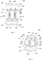
FIG. 1 is a top perspective view of a vertebral body implant; -
FIG. 2 is a side view of the implant ofFIG. 1 ; -
FIG. 3 is a cross-sectional view of the implant ofFIG. 1 taken alongline 3--3 in FIG. 58; -
FIG. 4 is an exploded side view of the implant ofFIG. 1 ; -
FIG. 5 is an exploded perspective view of the implant ofFIG. 1 ; -
FIG. 6 is a top perspective view of a body of the vertebral body implant ofFIG. 1 ,; -
FIG. 7 is a side view of the body ofFIG. 6 ; -
FIG. 8 is a perspective cross-sectional view of the body ofFIG. 6 taken alongline 8--8 inFIG. 7 ; -
FIG. 9 is a top view of the body ofFIG. 6 ; -
FIG. 10 is a cross-sectional view of the body ofFIG. 6 taken alongline 10--10 inFIG. 9 ; -
FIG. 11 is a cross-sectional view of the body ofFIG. 6 taken alongline 11--11 inFIG. 9 ; -
FIG. 12 is a perspective view of a rotating member of the vertebral body implant ofFIG. 1 ; -
FIG. 13 is a first end view of the rotating member ofFIG. 12 ; -
FIG. 14 is a second end view of the rotating member ofFIG. 12 ; -
FIG. 15 is a first end perspective view of an extension member of the vertebral body implant ofFIG. 1 ; -
FIG. 16 is a side view of the extension member ofFIG. 15 ; -
FIG. 17 is a second end perspective view of the extension member ofFIG. 15 ; -
FIG. 18 is an end view of the extension member ofFIG. 15 ; -
FIG. 19 is a perspective view of an insertion tool for the vertebral body implant ofFIG. 1 ; -
FIG. 20 is a side view of the insertion tool ofFIG. 19 ; -
FIG. 21 is an exploded view of two types of an insertion tool for the vertebral body implant ofFIG. 1 ; -
FIG. 22 is a perspective view of a vertebral body implant system including the implant ofFIG. 1 and a first insertion tool ofFIG. 19 ; -
FIG. 23 is a perspective view of the vertebral body implant system ofFIG. 22 with a tong member of the insertion tool engaging the vertebral body implant ofFIG. 1 ; -
FIG. 24 is a perspective view of a portion of the system ofFIG. 22 with the tool engaging the vertebral body implant in a first position; -
FIG. 25 is a perspective view of a portion of the system ofFIG. 22 with the tool engaging the vertebral body implant in a second position; -
FIG. 26 is a perspective view of another vertebral body implant system including the implant ofFIG. 1 and a second insertion tool in a first position; -
FIG. 27 is an enlarged perspective view of a portion of the system ofFIG. 26 ; -
FIG. 28 is a top perspective view of the vertebral body implant ofFIG. 1 in a second position and including a locking mechanism engaging the vertebral body implant ofFIG. 1 and a portion of the insertion tool ofFIG. 21 ; -
FIG. 29 is a side view of the vertebral body implant ofFIG. 1 in an expanded position with the locking mechanism engaging at least a portion of the implant -
FIG. 30 is a side view of the vertebral body implant ofFIG. 29 with the body ofFIG. 6 removed; -
FIG. 31 is another type of vertebral body device system including a vertebral body implant and insertion tool; -
FIG. 32 is an exploded perspective view of the system ofFIG. 31 ; -
FIG. 33 is a side view of the implant ofFIG. 31 and an end view of the insertion tool ofFIG. 31 ; -
FIG. 34 is a side view of the system ofFIG. 31 showing only a portion of the insertion tool; -
FIG. 35 is a side view of another a vertebral body implant; -
FIG. 36 is a cross-sectional view of the vertebral body implant ofFIG. 35 taken alongline 36--36 ofFIG. 35 and showing the angled set screw openings; -
FIG. 37 is another vertebral body system including an implant and insertion instrument; -
FIG. 38 is a partially exploded view of the vertebral body system ofFIG. 37 ; -
FIG. 39 is a perspective partially exploded view of another vertebral body system including an implant and an insertion instrument; -
FIG. 40 is another perspective partially exploded view of the vertebral body system ofFIG. 39 ; -
FIG. 41 is a perspective view of the system ofFIG. 39 with a transparent insertion instrument; -
FIG. 42 is a perspective view of avertebral body implant in an expanded position, in accordance with an aspect of the presently disclosed invention; -
FIG. 43 is a perspective view of a body of the vertebral body implant ofFIG. 42 , in accordance with an aspect of the present invention; -
FIG. 44 is a cross-sectional view of the vertebral body implant ofFIG. 42 taken alongline 44--44 inFIG. 42 with the extension members removed, in accordance with an aspect of the present invention; -
FIG. 45 is a side view of an extension member of the vertebral body implant ofFIG. 42 , in accordance with an aspect of the present invention; -
FIG. 46 is a top perspective view of the extension member ofFIG. 45 , in accordance with an aspect of the present invention; -
FIG. 47 is a side view of an internal locking member of the vertebral body implant ofFIG. 42 , in accordance with an aspect of the present invention; -
FIG. 48 is an end perspective view of the internal locking member ofFIG. 47 , in accordance with an aspect of the present invention; -
FIG. 49 is an exploded, perspective view of the vertebral body implant ofFIG. 42 , in accordance with an aspect of the present invention; -
FIG. 50 is an exploded, side view of the vertebral body implant ofFIG. 42 , in accordance with an aspect of the present invention; -
FIG. 51 is a perspective end view of the extension member of the vertebral body implantFIG. 42 , in accordance with an aspect of the present invention; and -
FIG. 52 is a side, cross-sectional view of the extension member taken alongline 52--52 inFIG. 51 , in accordance with an aspect of the present invention. - Generally stated, disclosed herein is an expandable vertebral body replacement device. Further, methods of assembling and using the expandable vertebral body replacement device are discussed.
- In this detailed description and the following claims, the words proximal, distal, anterior, posterior, medial, lateral, superior, inferior, cephalad, and caudal are defined by their standard usage for indicating a particular part of a bone or implant according to the relative disposition of the natural bone or directional terms of reference. For example, "proximal" means the portion of an implant nearest the insertion instrument, while "distal" indicates the portion of the implant farthest from the insertion instrument. As for directional terms, "anterior" is a direction towards the front side of the body, "posterior" means a direction towards the back side of the body, "medial" means towards the midline of the body, "lateral" is a direction towards the sides or away from the midline of the body, "superior" means a direction above, "inferior" means a direction below another object or structure, "cephalad" means a direction toward the head, and "caudal" means a direction toward the inferior part of the body.
- Referring to the drawings, wherein like reference numerals are used to indicate like or analogous components throughout the several views, and with particular reference to
FIGS. 1-5 , there is illustrated a vertebralbody replacement implant 500. Thevertebral body implant 500 may include abody 510, a first rotatingmember 530 rotatably coupled to thefirst end 512 of thebody 510, a secondrotating member 540 rotatably coupled to thesecond end 514 of thebody 510, afirst extension member 550 moveably coupled to afirst end 512 of thebody 510, and asecond extension member 570 moveably coupled to asecond end 514 of thebody 510. - As shown in
FIGS. 4-11 , thebody 510 may include anopening 516 extending from thefirst end 512 to thesecond end 514, for example, along the longitudinal axis of thebody 510. Theopening 516 may include at least twochannels body 510 from theopening 516. At least onefirst channel 517 may extend from thefirst end 512 toward thesecond end 514 and at least onesecond channel 518 may extend from thesecond end 514 toward thefirst end 512. At least onethird channel 519 may extend from thefirst end 512 to thesecond end 514. In the depicted body, the at least onefirst channel 517 may be onefirst channel 517, the at least onesecond channel 518 may be onesecond channel 518, and the at least onethird channel 519 may be, for example, fourchannels 519. Thechannels opening 516. As shown, thebody 510 may include, for example, onefirst channel 517 open on thefirst end 512, onesecond channel 518 open on thesecond end 514, and fourthird channels 519 open on both the first and second ends 512, 514. Alternative numbers ofchannels body 510 may include more orless channels - The exterior surface of the
body 510 may further include afirst groove 520 near thefirst end 512 and asecond groove 522 near thesecond end 514, as shown inFIGS. 4-7 . The first andsecond grooves body 510 and be sized to receive the first and secondrotating members groove opening 521 for receiving apin 506. As shown inFIGS. 4-6 , thebody 510 may also include at least oneaperture 524 positioned around the circumference of the exterior surface. The at least oneaperture 524 may be positioned, for example, at a midpoint between thefirst end 512 andsecond end 514 of thebody 510. The at least oneaperture 524 may be, for example, a threaded opening. Thebody 510 may also include at least onefirst locking hole 526 superior to theaperture 524 and at least onesecond locking hole 528 inferior to theaperture 524. Theaperture 524,first locking hole 526, andsecond locking hole 528 may be sized and shaped to receive alocking insert 590, as shown inFIGS. 28-30 . As illustrated, thebody 510 may include, for example, threeapertures 524, three first locking holes 526, and three second locking holes 528. The three sets ofopenings body 510 may further includeopenings 523 positioned around the circumference of thebody 510. Theopenings 523 may each include at least one gripping surface orregion 525 on each side of theopening 523 to couple to an insertion tool, such as,tool 600 described in greater detail below. As depicted, the three sets ofopenings openings 523 and adjacent to each other, such that, there are three solid portions of thebody 510 positioned between theopenings 523. - A rotating
members FIGS. 4 and5 and the rotatingmember 530 is shown in greater detail inFIGS. 12-14 . The firstrotating member 530 may include acenter opening 534 extending through the first rotatingmember 530. The exterior surface of the first rotatingmember 530 may include a plurality of grooves, notches, gear teeth, teeth, orscallops 532, as best seen inFIGS. 12 and 13 . The plurality ofnotches 532 may be, for example, sized to receive an insertion tool, such astool 600 described in greater detail below. The firstrotating member 530 may also includethreads 536 on the interior surface of themember 530, as shown inFIGS. 5 and12 . In addition, the first rotatingmember 530 may include at least oneprotrusion 538 positioned between eachnotch 532 to engage thegroove 520 in thebody 510. - The second
rotating member 540, as shown inFIGS. 4 and5 , may include a plurality ofnotches 542, acenter opening 544,threads 546, and at least oneprotrusion 548. The plurality ofnotches 542, center opening 544,threads 546, and at least oneprotrusion 548 may be of the type described above with reference to the plurality ofgrooves 532, center opening 534,threads 536, and at least oneprotrusion 538 of first rotatingmember 530, which will not be described again here for brevity's sake. - Referring now to
FIGS. 4 and5 , theextension members FIGS. 15-18 show thefirst extension member 550. Thefirst extension member 550 may include afirst end 552 and asecond end 554. Thefirst extension member 550 may also include a top portion orfirst end cap 556 at thefirst end 552 and at least oneleg member 562 extending away from thetop portion 556 and toward thesecond end 554. Thetop portion 556 may include a curvedtop surface 558, for example, a hemispherical or cylindrical shaped cup, and acenter opening 560, as shown inFIGS. 5 and15 . Thetop surface 558 may also includegrooves 559. The curvedtop surface 558,grooves 559, andcenter opening 560 may be configured to receive autologous bone graft or allograft material which will contact and allow for fusion with the adjacent vertebral bodies and additional graft material positioned between the at least oneleg member 562. Thecurved surface 558 may be, for example, sized to allow the graft material to be positioned within thefirst extension member 550 to minimize the height. In addition, the hemispherical shaped cup may be selected, for example, to minimize the amount of graft material necessary to fill thecurved surface 558. Thetop surface 558 may be, for example, coated, textured, porous, or of a trabecular metal nature to allow for bone growth into thefirst extension member 550 after implantation. In an alternative form, it is also contemplated that the curvedtop surface 558 may be, for example, a mesh or open slotted top surface to allow for the bone graft material positioned in thetop portion 556 to make contact with bone graft material positioned between the at least oneleg member 562. Thetop portion 556 may also be configured to receive, for example, end caps (not shown) with lordosis or a larger footprint to contact larger adjacent vertebral bodies at the outer ring of their end plates. - The at least one
leg member 562 may be, for example, threeleg members 562, as shown inFIGS. 15-18 . Theleg members 562 may includethreads 564 on an exterior surface. Thesecond end 554 of theleg members 562 may be, for example, tapered or angled. Theleg members 562 may include ashort leg member 562 and twolonger leg members 562. Theshort leg member 562 may be received within thechannel 517. A firstlonger leg member 562 may include a protrusion or hook 566 for engaging achannel 519 in thebody 510. Theprotrusion 566 may include an angled end, as shown inFIG. 16 , to engage at least oneretention pin 506 during use. A secondlonger leg member 562 may include, for example, a recessedregion 567. Thethreads 564 on thelegs 562 engage thethreads 536 on an interior surface of the first rotatingmember 530 to translate theleg member 562 with respect to thebody 510. Thethreads 564 may extend from thesecond end 554 to a bottom surface of thefirst end cap 556. Theleg members 562 may be curved to enable theleg members 562 to rotate with respect to the first rotatingmember 530. Thefirst extension member 550 may also includesupport members 568 positioned between and connected to theleg members 562. Thesupport members 568 may be, for example, cross-hatching braces positioned in rings. As depicted inFIGS. 15-18 , thesupport members 568 may, for example, extend out from the back side of theleg members 562 and be connected between theleg members 562 in "Y" or "T" shaped arrangements. Thesupport member 568 may also form an inner cylinder aligned with theopening 560 to form an inner channel through theimplant 500. The arrangement of theleg members 562 may be, for example, curved between theleg members 562 to form a ring-like shape. - The
second extension member 570, as shown inFIGS. 4 and5 , may include afirst end 572 and asecond end 574. Thesecond extension member 570 may also include a bottom portion orsecond end cap 576 at thefirst end 572 and at least oneleg member 582 extending away from thebottom portion 576 and to thesecond end 574. Thebottom portion 576 may include acurved bottom surface 578 and anopening 580. Thecurved bottom surface 578 may be of the type described above with respect to the curvedtop surface 558, which will not be described again here for brevity's sake. Thebottom surface 578 may also includegrooves 579. Thecurved bottom surface 578,grooves 579, andcenter opening 580 may also be configured to receive autologous bone graft or allograft material as described in greater detail above with respect to thefirst extension member 550. - The at least one
leg member 582 may be, for example, threeleg members 582 and may includethreads 584, protrusion orhook 586, andsupport members 588. Thethreads 584,protrusions 586, andsupport members 588 may be of the type described above with reference tothreads 564, protrusion orhook 566, andsupport members 568, which will not be described again here for brevity's sake. Thefirst end 572 of theleg members 582 may be, for example, tapered or angled. Theleg members 582 may include ashort leg member 582 and twolonger leg members 582. Theshort leg member 582 may be received within thechannel 518. A firstlonger leg member 582 may include a protrusion or hook 586 for engaging achannel 519 in thebody 510. Theprotrusion 586 may include an angled end, as shown inFIG. 5 , to engage at least oneretention pin 506 during use. A secondlonger leg member 582 may include, for example, a recessedregion 587. Thethreads 584 on thelegs 582 engage thethreads 546 on an interior surface of the second rotatingmember 540 to translate theleg member 582 with respect to thebody 510. Thethreads 584 may extend from thefirst end 572 to a bottom surface of thesecond end cap 576. Theleg members 582 may be curved to enable theleg members 582 to rotate with respect to the second rotatingmember 540. Thefirst extension member 550 may also includesupport members 588 positioned between and connected to theleg members 582. Thesupport members 588 may be, for example, cross-hatching braces positioned in rings. As depicted inFIGS. 15-18 , thesupport members 588 may, for example, extend out from the back side of theleg members 582 and be connected between theleg members 582 in "Y" or "T" shaped arrangements. Thesupport member 588 may also form an inner cylinder aligned with theopening 580 to form an inner channel through theimplant 500. The arrangement of theleg members 582 may be, for example, curved between theleg members 582 to form a ring-like shape. - The
implant 500 may also include alocking mechanism 590, as shown inFIGS. 28-30 . Thelocking mechanism 590 may include aplate 592 with a first locking pin or post 594, a second locking pin or post 596 and an opening (not shown), for example, a threaded opening. Thefirst locking post 594 is coupled to and extending away from the back surface of theplate 592. Thesecond locking post 596 coupled to and extending away from the back surface of theplate 592. The locking posts 594, 596 are sized and shaped to engage thelegs extension members plate 592 and sized and shaped to receive afastener 598 to lock theimplant 500 in a desired position. - The vertebral
body replacement device 500 may be assembled by obtaining abody 510 with a first rotatingmember 530 positioned in thefirst groove 520 and a secondrotating member 540 positioned in thesecond groove 522. Next, the first andsecond extension members channels opening 516 of thebody 510. Thefirst extension member 550 may be inserted into thechannels first end 512. During insertion into thechannels protrusion 566 of thefirst extension member 550 may be aligned with at least onechannel 519 on the interior surface of thebody 510. Thefirst extension member 550 may be translated until thethreads 564 of theleg members 562 engage theinterior threads 536 of the first rotatingmember 530. The firstrotating member 530 may be rotated until thefirst extension member 550 engages thefirst end 512 of thebody 510. Once thefirst extension member 550 is positioned in thebody 510, then, thesecond extension member 570 may be inserted into theopening 516. Thesecond extension member 570 may be inserted into thechannels second end 514. During insertion into thechannels protrusion 586 of thesecond extension member 570 may be aligned with at least onechannel 519 on the interior surface of thebody 510. The secondrotating member 540 may be rotated until thesecond extension member 570 engages thesecond end 514 of thebody 510. The locking plate may be coupled to theimplant 500 using theaperture 524 and lockingholes fastener 598 may be partially screwed into place, so that the locking plate is coupled to theimplant 500. - An
insertion tool 600 is shown inFIGS. 19-21 . Theinsertion tool 600 may include a gripping member ortong member 610, acompression sleeve 630, afirst deployment handle 640 and asecond deployment handle 650. The grippingmember 610 has afirst end 612 and asecond end 614 opposite thefirst end 612. Thesecond end 614 may include ahandle portion 616. Thefirst end 612 may include two grippingarms 618 and eachgripping arm 618 may include achannel 620 on an interior surface of the grippingarms 618. The grippingarms 618 sized and shaped to engage thegripping surfaces 525 on thebody 510. The grippingarms 618 are also sized and shaped to grasp grippingsurfaces 525 onbody 510 while a lockingmember 590 is attached to or assembled to thebody 510. The grippingarms 618 may be used to remove and reposition the lockingmember 590. The grippingmember 610 may also include an opening extending along the longitudinal axis of themember 610 from thefirst end 612 to thesecond end 614. Thecompression sleeve 630 including afirst end 632 and asecond end 634 opposite thefirst end 632. Thecompression sleeve 630 also including anopening 636 extending from thefirst end 632 to thesecond end 634 and sized to receive the grippingmember 610 and clamp the grippingarms 618 together to secure theimplant 500 to theinsertion tool 600. - As shown in
FIGS. 19-25 , thefirst deployment handle 640 includes afirst end 642 and asecond end 644 opposite thefirst end 642. Thefirst deployment handle 640 also includes anopening 646 extending from thefirst end 642 to thesecond end 644. Thefirst end 642 may also include a plurality ofprojections 648 sized and shaped to rotate the tworings extension members projections 648 may be, for example, cone shaped or angled toward the point of attachment with thefirst end 642 of thehandle 640 to allow for theprojections 648 to engage the grooves orteeth rotating members teeth projections 648 into theteeth projections 648 with respect to theteeth handle 610 is rotated. - Referring now to
FIGS. 21 ,26 , and27 , thesecond deployment handle 650 includes afirst end 652 and asecond end 654 opposite thefirst end 652. Thesecond deployment handle 650 also including anopening 656 extending between thefirst end 652 and thesecond end 654. Thefirst end 652 may also include asemi-circular protrusion 658 and the end of theprotrusion 658 may include a plurality ofprojections 660. The plurality ofprojections 660 may be, for example, cone shaped or angled toward the point of attachment with thesemi-circular protrusion 658 at thefirst end 652 of thehandle 650 to allow for theprojections 660 to engage the grooves orteeth rotating members teeth projections 660 into theteeth projections 660 with respect to theteeth handle 650 is rotated. Thesecond end 654 may also include asemi-circular protrusion 662 aligned with thesemi-circular protrusion 658 on thefirst end 652. - Referring now to
FIGS. 22-30 , methods of using thevertebral body implant 500 andinsertion instruments 600 are shown. The method includes obtaining avertebral body implant 500 and aninsertion instrument 600. Thevertebral body implant 500 andinsertion instrument 600 may be assembled as described in greater detail above, which will not be described again here for brevity's sake. Theinstrument 600 may then be coupled to thevertebral body device 500 by inserting the grippingarms 618 of the grippingmember 610 into theopenings 523 to engage thegripping surfaces 525, as shown inFIG. 23 . The grippingmember 610 may be preloaded with a lockingmember 590 positioned between the grippingarms 618. Thelocking mechanism 590 may engage theaperture 524 and lockingholes body 510. - Once the gripping
member 610 is coupled to theimplant 500, thecompression sleeve 630 may be inserted over the grippingmember 610. Thecompression sleeve 630 may engage the grippingmember 610 to secure the grippingarms 618 to theimplant 500 for insertion into the patient. Next, adeployment handle expansion members first deployment handle 640 may be selected. Alternatively, if the surgeon wants to extend only oneexpansion member second deployment handle 650 may be selected. - After the
deployment handle member 610 andcompression sleeve 630. The plurality ofprojections deployment handle notches rotating members deployment handle rotating members rotating members expansion members implant 500. Thefirst extension member 550 will translate in a superior direction increasing the height of thevertebral body implant 500. Thesecond extension member 570 will translate in an inferior direction increasing the height of thevertebral body implant 500. The amount of superior-inferior translation is limited by the length of theleg members deployment handle rotating members extension members vertebral body implant 500. Once the desired configuration and height of thevertebral body implant 500 is achieved, thelocking mechanism 590 may be tightened to lock thevertebral body implant 500 by inserting a driver through theinsertion instrument 600. Thelocking mechanism 590 may be tightened with, for example, a hex wrench inserted through the center opening 524 of theinstrument 600 to tighten thefastener 598 and secure thelocking plate 592 in place on theimplant 500. Thelocking mechanism 590 may engage theaperture 524 and lockingholes body 510. Alternatively, thelocking mechanism 590 may be inserted through theopening 622 in the grippingmember 610 once the desired expansion is achieved. After theimplant 500 is secured in the desired expanded position, theinsertion tool 600 may be removed from thevertebral body implant 500. - Another vertebral
body replacement device 700 andinsertion instrument 800 are shown inFIGS. 31-34 . Thevertebral body device 700 may include abody 710, a first rotatingmember 730 rotatably coupled to thefirst end 712 of thebody 710, a secondrotating member 740 rotatably coupled to thesecond end 714 of thebody 710, afirst extension member 750 moveably coupled to thefirst end 712 of thebody 710, and asecond extension member 770 moveably coupled to asecond end 714 of thebody 710. - As shown in
FIG. 32 , thebody 710 may include an opening (not shown) extending from thefirst end 712 to thesecond end 714, for example, along the longitudinal axis of thebody 710. The opening (not shown) may include at least two channels (not shown) extending into thebody 710 from the opening. The opening and channels may be of the type described above with reference toopening 516 andchannels body 710 may further include afirst groove 720 near thefirst end 712 and asecond groove 722 near thesecond end 714, as shown inFIG. 32 . The first andsecond grooves body 710 and be sized to receive the first and secondrotating members FIGS. 32 and34 , thebody 710 may also include at least onedriver slot driver slots body 710 each spaced 60° apart from each other. Thebody 710 may also include at least onedriver hole 724 positioned between thedriver slots openings implant 700 in the desired expansion. Theopenings first opening 727 may be positioned superior to thedriver slots second opening 729 may be positioned inferior to thedriver slots body 710 may also include at least oneopening 729 positioned on the non-locking faces. The at least oneopening 729 may be sized and shaped to optimize bone grafting. - Rotating
members FIG. 32 and the first rotatingmember 730 may include a center opening (not shown) extending through the first rotatingmember 730. The exterior surface of the first rotatingmember 730 may include a plurality of grooves, notches, gear teeth, teeth, orscallops 732, as best seen inFIGS. 32-34 . The plurality ofnotches 732 may be, for example, sized to receive an insertion tool, such astool 800 described in greater detail below. The firstrotating member 730 may also include threads (not shown) on the interior surface of themember 730. - The second
rotating member 740, as shown inFIG. 32 , may include a plurality ofnotches 742, a center opening (not shown), and threads (not shown). The plurality ofnotches 542, center opening (not shown), and threads (not shown) may be of the type described above with reference to the plurality ofgrooves 732, center opening (not shown), and threads (not shown) of first rotatingmember 730, which will not be described again here for brevity's sake. - Referring now to
FIG. 32 , theextension members first extension member 750 may include afirst end 752 and asecond end 754. Thefirst extension member 750 may also include a top portion orfirst end cap 756 at thefirst end 752 and at least oneleg member 762 extending away from thetop portion 756 and toward thesecond end 754. Thetop portion 756 may include atop surface 758 and a center opening 760. Thetop surface 758 may also include grooves 759. Thetop surface 758, grooves 759, and center opening 760 may be configured to receive autologous bone graft or allograft material which will contact and allow for fusion with the adjacent vertebral bodies and additional graft material positioned between the at least oneleg member 562. Thesurface 758 may be, for example, sized to allow the graft material to be positioned within thefirst extension member 750 to minimize the height. In addition, thetop surface 758 may be shaped, for example, to receive graft material to allow for bone ingrowth to achieve the desired fusion. Thetop surface 758 may be, for example, coated, textured, porous, or of a trabecular metal nature to allow for bone growth into thefirst extension member 750 after implantation. In an alternative, it is also contemplated that the curvedtop surface 758 may be, for example, a mesh or open slotted top surface to allow for the bone graft material positioned in thetop portion 756 to make contact with bone graft material positioned between the at least oneleg member 762. Thetop portion 756 may also be configured to receive, for example, end caps (not shown) with lordosis or a larger footprint to contact larger adjacent vertebral bodies at the outer ring of their end plates. - The at least one
leg member 762 may be, for example, threeleg members 762, as shown inFIGS. 32-34 . Theleg members 762 may includethreads 764 on an exterior surface. Theleg members 762 may include ashort leg member 762 and twolonger leg members 762. Theshort leg member 762 may be received within a channel which does not extend the entire length of thebody 710. In one form, as shown inFIG. 32 , theshorter leg member 762 may include a protrusion or hook 766 positioned on the distal portion of theleg member 762. The protrusion or hook 766 may be sized and shaped to engage a retention pin, for example, theprotrusion 766 may include a proximal portion that is angled toward theleg member 762 creating a recess for receiving the retention pin. Thelonger leg members 762 may each be received within a channel which extends through the entire length of thebody 710. Thelonger leg members 762 may each include, for example, a recessedregion 765. In an alternative , for example, one of thelonger leg members 762 may include the protrusion orhook 766 and theshorter leg member 762 and the secondlonger leg member 762 may each include a recessedregion 765. Thethreads 764 on thelegs 762 engage the threads 736 on an interior surface of the first rotatingmember 730 to translate theleg member 762 with respect to thebody 710. Thethreads 764 may extend from thesecond end 754 to a bottom surface of thefirst end cap 756. Theleg members 762 may be curved to enable theleg members 762 to rotate with respect to the first rotatingmember 730. Thefirst extension member 750 may also includesupport members 768 positioned between and connected to theleg members 762. Thesupport members 768 may be, for example, cross-hatching braces positioned in rings. As depicted inFIGS. 32 , thesupport members 768 may, for example, extend out from the back side of theleg members 762 and be connected between theleg members 762 in "Y" or "T" shaped arrangements. Thesupport member 768 may alternatively form an inner cylinder aligned with the opening 760 to form an inner channel through theimplant 700. The arrangement of theleg members 762 may be, for example, curved between theleg members 762 to form a ring-like shape. - The
second extension member 770, as shown inFIG. 32 , may include afirst end 772 and asecond end 774. Thesecond extension member 770 may also include a bottom portion orsecond end cap 776 at thefirst end 772 and at least oneleg member 782 extending away from thebottom portion 776 and to thesecond end 774. Thebottom portion 776 may include acurved bottom surface 778 and an opening 780. Thecurved bottom surface 778 may be of the type described above with respect to the curvedtop surface 758, which will not be described again here for brevity's sake. Thebottom surface 778 may also includegrooves 779. Thecurved bottom surface 778,grooves 779, and center opening 780 may also be configured to receive autologous bone graft or allograft material as described in greater detail above with respect to thefirst extension member 750. - The at least one
leg member 782 may be, for example, threeleg members 782 and may includethreads 784, protrusion orhook 786, andsupport members 788. Thethreads 784,protrusions 786, andsupport members 788 may be of the type described above with reference tothreads 764, protrusion orhook 766, andsupport members 768, which will not be described again here for brevity's sake. Theleg members 782 may include ashort leg member 782 and twolonger leg members 782. Theshort leg member 782 may be received within a channel which extends along a portion of the length of thebody 710. A firstlonger leg member 782 may include a protrusion or hook 786 for engaging a channel 719 in thebody 710. A secondlonger leg member 782 may include, for example, a recessed region 787. Thethreads 784 on thelegs 782 engage the threads 746 on an interior surface of the second rotatingmember 740 to translate theleg member 782 with respect to thebody 710. Thethreads 784 may extend from thefirst end 772 to a bottom surface of thesecond end cap 776. Theleg members 782 may be curved to enable theleg members 782 to rotate with respect to the second rotatingmember 740. Thefirst extension member 750 may also includesupport members 788 positioned between and connected to theleg members 782. Thesupport members 788 may be, for example, cross-hatching braces positioned in rings. As depicted inFIG. 32 , thesupport members 788 may, for example, extend out from the back side of theleg members 782 and be connected between theleg members 782 in "Y" or "T" shaped arrangements. Thesupport member 788 may alternatively form an inner cylinder aligned with the opening 780 to form an inner channel through theimplant 700. The arrangement of theleg members 782 may be, for example, curved between theleg members 782 to form a ring-like shape. - As shown in
FIGS. 32-33 , theinsertion instrument 800 may includeshifter 810, agripper member 820, a lockingsleeve 840, and adriver sleeve 850. Theshifter 810 includes afirst end 812, asecond end 814, anextension member 816 and ahandle 818. Thegripper member 820 includes afirst end 822, asecond end 824 and anopening first end 822 and thesecond end 824. Thegripper member 820 may also include at least twogripper arms 826 sized and shaped to engage thebody 710 of theimplant 700. Theopening slot 828 extending in a superior-inferior direction, afirst opening 830 positioned at the superior end of theslot 828 and asecond opening 832 positioned at the inferior end of theslot 828. Theopening shifter 810. - With continued reference to
FIG. 32 , the lockingsleeve 840 may include anopening 842 extending from a first end to a second end of the lockingsleeve 840. Theopening 842 may be sized and shaped to receive thegripper member 820 to secure the grippingarms 826 to theimplant 700. Thedrive sleeve 850 may include afirst end 852 and asecond end 854. Thedriver sleeve 850 may also include anopening 856 extending from thefirst end 852 to thesecond end 854 and a plurality of projections, protrusions, teeth, orgear members 858 for engaging the rotatingmembers projections 858 may be, for example, cone shaped or angled toward the point of attachment with the first end of thedrive sleeve 850 to allow for theprojections 858 to engage the grooves orteeth rotating members teeth projections 858 into theteeth projections 858 with respect to theteeth drive sleeve 850 is rotated. - Referring now to
FIGS. 33-34 , theextension member 816 of theshifter 810 engages theslots driver sleeve 850 from engagement with the first rotatingmember 730 to the second rotatingmember 740 and vice versa. Theshifter 810 may be positioned in thefirst opening 830 to engage the second rotatingmember 740, as shown inFIG. 33 , and in thesecond opening 832 to engage the first rotatingmember 730. Once anextension member respective opening extended extension member extension member second extension member -
FIGS. 35-36 show another vertebralbody replacement implant 900. Theimplant 900 may include abody 910, a first rotatingmember 930 rotatably coupled to thefirst end 912 of thebody 910, a secondrotating member 940 rotatably coupled to thesecond end 914 of thebody 910, afirst extension member 950 moveably coupled to thefirst end 912 of thebody 910, and asecond extension member 970 moveably coupled to asecond end 914 of thebody 910. The body may include afirst end 912 and asecond end 914. As shown inFIG. 36 , thebody 910 may include a firstangled opening 916 and a secondangled opening 918. Theangled openings angled opening 916 may extend in a superior direction and the secondangled opening 918 may extend in an inferior direction. The firstrotating member 930 and the second rotatingmember 940 may be of the type described above with reference to rotatingmembers first extension member 950 andsecond extension member 970 may be of the type described above with reference toextension members - Another vertebral
body replacement system 1000 is shown inFIGS. 37-38 . Thesystem 1000 includes animplant 1002 and adriver sleeve 1100. Theimplant 1002 may include abody 1010, a first rotatingmember 1030 rotatably coupled to thefirst end 1012 of thebody 1010, a secondrotating member 1040 rotatably coupled to the second end 1014 of thebody 1010, afirst extension member 1050 moveably coupled to thefirst end 1012 of thebody 1010, and asecond extension member 1070 moveably coupled to a second end 1014 of thebody 1010. The body may include afirst end 1012 and a second end 1014. As shown inFIGS. 37-38 , thebody 1010 may include at least oneopening 1012. Theopenings 1012 may be, for example, threaded openings. The first rotatingmember 1030 and the second rotatingmember 1040 may be of the type described above with reference to rotatingmembers first extension member 1050 andsecond extension member 1070 may be of the type described above with reference toextension members - The
driver sleeve 1100 may include abody 1102 and adriver head 1120 at a first end of thebody 1102. Thedriver head 1120 may include a pivotingmember 1110 coupled to thebody 1102 and a plurality of projections, protrusions, teeth,gear members 1122 for engaging therotating members projections 1122 may be, for example, cone shaped or angled toward the point of attachment with the first end of thedriver head 1120 to allow for theprojections 1122 to engage the grooves or teeth 1032, 1042 of therotating members projections 1122 into the teeth 1032, 1042 and prevent jumping of theprojections 1122 with respect to the teeth 1032, 1042 as thedriver head 1120 andbody 1102 are rotated. The pivotingmember 1110 may be, for example, a splined end that allows for thedriver 1100 to pivot at an angle while being rotated to turn therotating members -
FIGS. 39-41 illustrate another vertebralbody replacement system 1200. Thesystem 1200 includes animplant 1202 and adrive mechanism 1300. Theimplant 1202 may include abody 1210, a first rotatingmember 1230 rotatably coupled to the first end of thebody 1210, a secondrotating member 1240 rotatably coupled to the second end of thebody 1210, a first extension member (not shown) moveably coupled to the first end of thebody 1210, and a second extension member (not shown) moveably coupled to a second end of thebody 1210. Thebody 1210 include at least oneopening 1212. Theopening 1212 may be sized to engage thedrive sleeve 1300. The first rotatingmember 1230 and the second rotatingmember 1240 may be of the type described above with reference to rotatingmembers extension members - The
drive sleeve 1300 may include abody 1302 and acoupling protrusion 1304. The coupling protrusion engages theopening 1212 in thebody 1210. Thedrive sleeve 1300 is then positioned for engagement with one of therotating members implant 1202. Although not shown, a deployment handle, such as deployment handles 640, 650 as described in greater detail above, may be slid over thebody 1302 to engage one of therotating members implant 1202. Once a first rotatingmember teeth drive sleeve 1300 may be rotated to a second position and the deployment handle (not shown) positioned to engage the second rotatingmember implant 1200. Theimplant 1200 may be secured in the expanded position by inserting locking mechanisms (not shown) into theopenings opening 1214 and engage at least a portion of the first extension member (not shown) to secure the first extension member in the desired expanded position. A second locking mechanism (not shown) may extend through theopening 1216 and engage at least a portion of the second extension member (not shown) to secure the second extension member in the desired expanded position. - Referring now to
FIGS. 42-52 , another vertebralbody replacement implant 1500 in accordance with the invention is shown. Thevertebral body implant 1500 may include abody 1510, a first rotatingmember 530 rotatably coupled to thefirst end 1512 of thebody 1510, a secondrotating member 540 rotatably coupled to thesecond end 1514 of thebody 1510, afirst extension member 1550 coupled to afirst end 1512 of thebody 1510, and thesecond extension member 1570 coupled to asecond end 1514 of thebody 1510. The firstrotating member 530 and the second rotatingmember 540 are as described in greater detail above with reference toFIGS. 1-30 and will not be described again here for brevity's sake. - As shown in
FIGS. 43 ,44 ,49 and50 , thebody 1510 may include anopening 1516 extending from thefirst end 1512 to thesecond end 1514, for example, along the longitudinal axis of thebody 1510. Theopening 1516 may include at least twochannels body 1510 from theopening 1516. At least onefirst channel 1517 may extend from thefirst end 1512 towards thesecond end 1514. At least onesecond channel 1518 may extend from thesecond end 1514 toward thefirst end 1512. At least onethird channel 1519 may extend from thefirst end 1512 to thesecond end 1514. In the depicted embodiment, the at least onefirst channel 1517 may be onefirst channel 1517, that at least onesecond channel 1518 may be onesecond channel 1518, and the at least onethird channel 1519 may be, for example, forchannels 1519. Thechannels opening 1516. As shown, thebody 1510 may include, for example, onefirst channel 1517 open on thefirst end 1512, onesecond channel 1518 open on thesecond end 1514, and fourthird channels 1519 open on both the first andsecond ends channels body 1510 may include more orless channels - The exterior surface of the
body 1510 may further include afirst groove 1520 near thefirst end 1512 at asecond groove 1522 near thesecond end 1514, as shown inFIGS. 43 ,44 ,49 and50 . The first andsecond grooves body 1510 and be sized to receive the first and secondrotating members groove opening 1521 for receiving apin 1506. As shown inFIGS. 42-44 ,49 and50 , thebody 1510 may also include at least oneaperture 1606 positioned around the circumference of the exterior surface. The at least oneaperture 1606 may be positioned, for example, at a midpoint between thefirst end 1512 and thesecond end 1514 of thebody 1510. The at least oneaperture 1606 may be, for example, a threaded opening. The at least oneaperture 1606 may also be surrounded by a recessed region or countersunkshelf 1607, as shown inFIG. 43 and50 . The countersunkshelf 1607 allows ascrew 1604 to be inserted into thebody 1510 flush with the exterior surface of thebody 1510. Thebody 1510 may also include at least one firstguide pin hole 1605 superior to theaperture 1606 and at least one secondguide pin hole 1605 inferior to theaperture 1606. Theaperture 1606 may be sized and shaped to receive a fastener orscrew 1604, as shown inFIGS. 42 ,44 ,49 and50 . The firstguide pin hole 1605 and secondguide pin hole 1605 may be sized and shaped to receive alocking insert 1600, as shown inFIGS. 42 ,44 ,49 and50 . In the depicted embodiment, oneaperture 1606 surrounded by the first and second guide pin holes 1605 is shown, however,additional apertures 1606 and guidepin holes 1605 positioned around the circumference of thebody 1510 are also contemplated. Thebody 1510 may further includeopenings 1523 positioned around the circumference of thebody 1510. Theopenings 1523 may, for example, be separated by a gripping surface or recessedregion 1525. The recessedregions 1525 may be used, for example, to couple to an insertion tool (not shown). As depicted, the three sets ofopenings regions 1525. - Referring now to
FIGS. 42 ,45 ,46 ,49 and50 , theextension members FIGS. 45 and 46 show thefirst extension member 1550. Thefirst extension member 1550 may include afirst end 1552 and asecond end 1554. Thefirst extension member 1550 may also include a top portion orfirst end cap 556 at thefirst end 1552 and at least oneleg member 1562 extending away from thetop portion 556 and toward thesecond end 1554. Thetop portion 556 may include a curvedtop surface 558,grooves 559, and acenter opening 560, as described in greater detail above with reference toimplant 500 and which will not be described again here for brevity sake. - The at least one
leg member 1562 may be, for example, threeleg members 1562, as shown inFIGS. 49-51 . Theleg members 1562 may includethreads 1564 on an exterior surface. Thesecond end 1554 of theleg members 1562 may be, for example, tapered or angled. Theleg members 1562 may include ashort leg member 1562 and twolonger leg members 1562. Theshort leg member 1562 may be received within thechannel 1517 and include, for example, a recessedregion 1567, as shown inFIGS. 46 ,49 ,51 and 52 . A firstlonger leg member 1562 may include a protrusion orhook 1566 for engaging achannel 1519 in thebody 1510. Theprotrusion 1566 may include anangled end 1569, as shown inFIG. 52 , to engage at least oneretention pin 1506 during use. Theprotrusion 1566 may have a recess positioned adjacent to theprotrusion 1566 and the remaining interior surface of theleg member 1562 may extend into the center of theextension member 1550, for example, approximately the same distance as theprotrusion 1566. - The
threads 1564 on thelegs 1562 engage thethreads 536 on an interior surface of the first rotatingmember 530 to translate theleg member 1562 with respect to thebody 1510. Thethreads 564 may extend from thesecond end 1554 to a bottom surface of thefirst end cap 556. Theleg members 1562 may be curved to enable theleg members 1562 to rotate with respect to the first rotatingmember 530. Thefirst extension member 1550 may also include at least onesupport member 1568 positioned between and connected to theleg members 1562. The at least onesupport member 1568 may be, for example, inset into theextension member 1550 with respect to the exterior surface of theleg members 1562. As depicted inFIGS. 51-52 , thesupport members 1568 may, for example, form an inner structure surrounding theopening 560 to form an inner channel through theimplant 1500. The arrangement of theleg members 1562 may be, for example, straight or curved between theleg members 1562. - The
second extension member 1570, as shown inFIGS. 42 ,49 and50 , may include afirst end 1572 and asecond end 1574. Thesecond extension member 1570 may also include a bottom portion orsecond end cap 576 at thefirst end 1572 and at least oneleg member 1582 extending away from thebottom portion 576 and to thefirst end 1572. Thebottom portion 576 may include acurved bottom surface 578,grooves 579 and anopening 580, as described in greater detail above with reference toimplant 500 and which will not be described again here for brevity's sake. - The at least one
leg member 1582 may be, for example, threeleg members 1582 and may includethreads 1584, protrusion orhook 1586, andsupport members 1588. Thethreads 1584,protrusions 1586, andsupport members 1588 may be of the type described above with reference tothreads 1564, protrusion orhook 1566, andsupport members 1568, which will not be described again here for brevity's sake. Thefirst end 1572 of theleg members 1582 may be, for example, tapered or angled. Theleg members 1582 may include ashort leg member 1582 and twolonger leg members 1582. Theshort leg member 1582 may be received within thechannel 1518 and include, for example, a recessedregion 1587, as shown inFIG. 49 . A firstlonger leg member 1582 may include a protrusion orhook 1586 for engaging achannel 1519 in thebody 1510. Theprotrusion 1586 may include an angled end to engage at least oneretention pin 1506 during use. Theprotrusion 1586 may have a recess positioned adjacent to theprotrusion 1586 and the remaining interior surface of theleg member 1582 may extend into the center of theextension member 1570, for example, approximately the same distance as theprotrusion 1586. - The
threads 1584 on thelegs 1582 engage thethreads 546 on an interior surface of the second rotatingmember 540 to translate theleg member 1582 with respect to thebody 1510. Thethreads 1584 may extend from thefirst end 1572 to a bottom surface of thesecond end cap 576. Theleg members 1582 may be curved to enable theleg members 1582 to rotate with respect to the second rotatingmember 540. Thesecond extension member 1570 may also include at least onesupport member 1588 positioned between and connected to theleg members 1582. The at least onesupport member 1588 may be, for example, inset into theextension member 1570 with respect to the exterior surface of theleg members 1582. As shown with respect toextension member 1550 inFIGS. 51-52 , thesupport members 1588 may, for example, form an inner structure surrounding theopening 580 to form an inner channel through theimplant 1500. The arrangement of theleg members 1582 may be, for example, straight or curved between theleg members 1582. - The
implant 1500 may also include a locking mechanism, locking insert, orinternal friction lock 1600, as shown inFIGS. 42 ,44 , and47-50 . Thelock 1600 may include abody portion 1602 and guidepins 1601 coupled to the front side of thebody portion 1602. As shown, thelock 1600 may include, for example, two guide pins 1601. Thelock 1600 may also include a threadedopening 1603 for receiving a screw orfastener 1604, as shown inFIGS. 42 and44 . The threadedopening 1603 may extend through thebody portion 1602 from a front side to a back side. The guide pins 1601 may extend away from the front side of thebody portion 1602 above and below the threadedopening 1603. Thebody portion 1602 may also include two surfaces, friction surfaces, or presslegs 1610 for engaging the interior wall of thebody 1510. The back side of thebody portion 1602 may be, for example, wider than the front side of thebody portion 1602. - The vertebral
body replacement device 1500 may be assembled by obtaining abody 1510 with a first rotatingmember 530 positioned in thefirst groove 1520 and a secondrotating member 540 positioned in thesecond groove 1522. Next, the first andsecond extension members channels opening 1516 of thebody 1510. Thefirst extension member 1550 may be inserted, for example, into thechannels first end 1512. During insertion into thechannels protrusion 1566 of thefirst extension member 1550 may be aligned with at least onechannel 1519 on the interior surface of thebody 1510. Thefirst extension member 1550 may be translated until thethreads 1564 of theleg members 1562 engage the interior threads 1536 of the first rotatingmember 530. The firstrotating member 530 may be rotated until thefirst extension member 1550 engages thefirst end 1512 of thebody 1510. Once thefirst extension member 1550 is positioned in thebody 1510, thesecond extension member 1570 may be inserted into theopening 1516, or vice versa. Thesecond extension member 1570 may be inserted into thechannels second end 1514. During insertion into thechannels protrusion 1586 of thesecond extension member 1570 may be aligned with at least onechannel 1519 on the interior surface of thebody 1510. The secondrotating member 540 may be rotated until thesecond extension member 1570 engages thesecond end 1514 of thebody 1510. Thelocking mechanism 1600 may be coupled to theimplant 1500 using the locking holes 1605. Thefastener 1604 may be coupled to theimplant 1500 using theaperture 1524 and may be partially screwed into place, so that thelocking mechanism 1600 is coupled to theimplant 1500. Once a desired position has been achieved for theextension members implant 1500, thescrew 1604 may be tightened to secure thelocking mechanism 1600 to thebody 1510 and fix the members of theimplant 1500 from rotating. - A method of using an expandable cage system as disclosed herein, comprises:
- obtaining a vertebral body implant, the vertebral body implant comprising:
- a body with a first end and a second end;
- a first rotating member rotatably coupled to the first end;
- a second rotating member rotatably coupled to the second end;
- first extension member moveably coupled to the first end; and
- a second extension member moveably coupled to the second end;
- obtaining an insertion instrument;
- coupling the vertebral body implant to the insertion instrument;
- inserting the vertebral body implant into a patient between two vertebral bodies;
- expanding the vertebral body implant; and
- removing the insertion instrument.
- The insertion instrument may comprise:
- a gripping member;
- a compression sleeve sized to engage the gripping member; and
- at least one rotating member sized to receive the compression sleeve and gripping member.
- The method may comprise:
inserting a locking member into the body of the vertebral body implant. - In the method, expanding the vertebral body implant may comprise:
rotating the rotating member in a first direction to engage and rotate the first rotating member, wherein rotating the first rotating member translates the coupled first extension member to increase a height of the vertebral body device. - In the method, expanding the vertebral body implant may comprise:
expanding only one of the first extension member and the second extension member. - Optionally, in the method, the at least one rotating member comprises:
a first end having a semi-circular protrusion and a plurality of projections positioned around the protrusion on the first end, wherein the semi-circular protrusion engages one of the first rotating member and the second rotating member to expand one of the first extension member and the second extension member. - In the method, inserting a locking member into the body of the vertebral body implant may comprise:
- obtaining a locking plate with a first post, a second post and a bore located between the first post and the second post;
- inserting a threaded fastener through the bore in the locking plate and a threaded opening in the body of the vertebral body implant; and
- tightening the threaded fastener to insert the first post into an opening superior to the bore and to insert the second post into an opening inferior to the bore, wherein the first post engages the first extension member and the second post engages the second extension member to secure the vertebral A method of using an expandable cage system, comprising:
- obtaining a vertebral body implant, the vertebral body implant comprising:
- a body with a first end and a second end;
- a first rotating member rotatably coupled to the first end;
- a second rotating member rotatably coupled to the second end;
- first extension member moveably coupled to the first end; and
- a second extension member moveably coupled to the second end;
- obtaining an insertion instrument;
- coupling the vertebral body implant to the insertion instrument;
- inserting the vertebral body implant into a patient between two vertebral bodies;
- expanding the vertebral body implant; and
- removing the insertion instrument.
- obtaining a vertebral body implant, the vertebral body implant comprising:
- The insertion instrument may comprise:
- a gripping member;
- a compression sleeve sized to engage the gripping member; and
- at least one rotating member sized to receive the compression sleeve and gripping member.
- The method may comprise:
inserting a locking member into the body of the vertebral body implant. - In the method, expanding the vertebral body implant may comprise:
rotating the rotating member in a first direction to engage and rotate the first rotating member, wherein rotating the first rotating member translates the coupled first extension member to increase a height of the vertebral body device. - In the method, expanding the vertebral body implant may comprise:
expanding only one of the first extension member and the second extension member. - Optionally, in the method, the at least one rotating member comprises:
a first end having a semi-circular protrusion and a plurality of projections positioned around the protrusion on the first end, wherein the semi-circular protrusion engages one of the first rotating member and the second rotating member to expand one of the first extension member and the second extension member. - I In the method, inserting a locking member into the body of the vertebral body implant may comprise:
- obtaining a locking plate with a first post, a second post and a bore located between the first post and the second post;
- inserting a threaded fastener through the bore in the locking plate and a threaded opening in the body of the vertebral body implant; and
- tightening the threaded fastener to insert the first post into an opening superior to the bore and to insert the second post into an opening inferior to the bore, wherein the first post engages the first extension member and the second post engages the second extension member to secure the vertebral body implant in an expanded position.
- As may be recognized by those of ordinary skill in the art based on the teachings herein, numerous changes and modifications may be made to the above-described and other embodiments of the present disclosure without departing from the scope of the disclosure. The implants, devices, systems, and their components as disclosed in the specification, including the accompanying abstract and drawings, may be replaced by alternative component(s) or feature(s), such as those disclosed in another embodiment, which serve the same, equivalent or similar purpose as known by those skilled in the art to achieve the same, equivalent or similar results by such alternative component(s) or feature(s) to provide a similar function for the intended purpose. In addition, the devices, implants and systems may include more or fewer components or features than the embodiments as described and illustrated herein. For example, the components and features of the vertebral body implants of
FIGS. 1-30 ,FIGS. 31-34 ,FIGS. 35-36 ,FIGS. 37-38 ,FIGS. 39-41 , andFIGS. 42-52 may all be used interchangeably and in alternative combinations as would be modified or altered by one of skill in the art. Accordingly, this detailed description of the currently-preferred embodiments is to be taken in an illustrative, as opposed to limiting of the disclosure. - The terminology used herein is for the purpose of describing particular embodiments only and is not intended to be limiting of the invention. As used herein, the singular forms "a", "an" and "the" are intended to include the plural forms as well, unless the context clearly indicates otherwise. It will be further understood that the terms "comprise" (and any form of comprise, such as "comprises" and "comprising"), "have" (and any form of have, such as "has", and "having"), "include" (and any form of include, such as "includes" and "including"), and "contain" (and any form of contain, such as "contains" and "containing") are open-ended linking verbs. As a result, a method or device that "comprises," "has," "includes," or "contains" one or more steps or elements possesses those one or more steps or elements, but is not limited to possessing only those one or more steps or elements. Likewise, a step of a method or an element of a device that "comprises," "has," "includes," or "contains" one or more features possesses those one or more features, but is not limited to possessing only those one or more features. Furthermore, a device or structure that is configured in a certain way is configured in at least that way, but may also be configured in ways that are not listed.
- The invention has been described with reference to the preferred embodiments. It will be understood that the architectural and operational embodiments described herein are exemplary of a plurality of possible arrangements to provide the same general features, characteristics, and general system operation. Modifications and alterations will occur to others upon a reading and understanding of the preceding detailed description. It is intended that the invention be construed as including all such modifications and alterations.
Claims (15)
- A vertebral body implant, comprising:a body with a first end and a second end;a first rotating member rotatably coupled to the first end, the first end comprises a plurality of first notches inset into the first rotating member;a first extension member moveably coupled to the first end.
- The vertebral body implant of claim 1, further comprising:a second rotating member rotatably coupled to the second end, the second end comprises a plurality of second notches inset into the second rotating member; anda second extension member moveably coupled to the second end.
- The vertebral body implant of any one of claims 1-2, the body further comprising:at least one aperture positioned at a midpoint between the first end and the second end;at least one first locking hole positioned superior to the at least one aperture; andat least one second locking hole positioned inferior to the at least one aperture.
- The vertebral body implant of claim 3, further comprising:a locking plate with a first post positioned in the at least one first locking hole,a second post positioned in the at least one second locking hole, anda bore located between the first post and the second post, wherein the bore is concentric to the at least one aperture.
- The vertebral body implant of any one of claims 3-4, the locking plate further comprising:
a threaded fastener;the threaded fastener extending through the bore of the locking plate and the at least one aperture of the body; andthe threaded fastener is capable of positioning the locking plate against the first and second extension members preventing further extension. - The vertebral body implant of any one of claims 3-5, the body further comprising:at least two solid faces and at least two bone grafting windows;the solid faces and bone grafting windows alternating around the body; andat least one solid face further comprises:
an aperture, a first locking hole and a second locking hole. - The vertebral body device of any one of claims 2-6, the first rotating member further comprising:a center opening forming an interior surface, the interior surface comprising:threads positioned on the interior surface; andthe plurality of first notches opening toward an inferior end; andthe second rotating member further comprising:
a center opening forming an interior surface, the interior surface comprising:threads positioned on the interior surface; andthe plurality of second notches opening toward a superior end. - The vertebral body device of any one of claims 2-7, the first extension member further comprising:a top portion;at least one first leg member extending away from the top portion, the at least one first leg member further comprising:threads positioned on an exterior surface of the at least one first leg member and configured to engage the threads on the interior surface of the first rotating member; anda protrusion positioned on a second end of the at least one first leg member and configured to engage a stop member coupled to the body; andat least one first support member positioned between and coupled to the at least one first leg member;the second extension member further comprising:a bottom portion;at least one second leg member extending away from the bottom portion, the at least one second leg member further comprising:threads positioned on an exterior surface of the at least one second leg member and configured to engage the threads on the interior surface of the second rotating member; anda protrusion positioned on a second end of the at least one second leg member and configured to engage a pin coupled to the body; andat least one second support member positioned between and coupled to the at least one second leg member.
- An expandable cage system, comprising:a vertebral body device, comprising:a body with a first end and a second end, the body comprising:at least one aperture positioned on the body along a midpoint between the first end and the second end;at least one first locking hole positioned superior to the at least one aperture; andat least one second locking hole positioned inferior to the at least one aperture;a first rotating member coupled to the first end;a second rotating member coupled to the second end;a first extension member moveably coupled to the first end; anda second extension member moveably coupled to the second end; andan insertion instrument, the insertion instrument being sized to be placed around the at least one aperture, the at least one first locking hole, and the at least one second locking hole.
- The expandable cage system of claim 9, the insertion instrument comprising:a gripping member;a compression sleeve sized to engage the gripping member; andat least one rotating member sized to receive the compression sleeve and gripping member.
- The expandable cage system of claim 10, the body further comprising:
at least one opening positioned on each side of the at least one aperture, the at least one opening being adapted for insertion and engaging of the gripping member. - The expandable cage system of any one of claims 10-11, the at least one rotating member further comprising:
a first end having a plurality of projections positioned around the circumference of the first end. - The expandable cage system of any one of claims 10-11, the at least one rotating member further comprising:
a first end having a first semi-circular protrusion and a plurality of projections positioned around the first protrusion on the first end. - The expandable cage system of claim 12, where the at least one rotating member further comprises:
a second end having a second semi-circular protrusion extending away from the second end and aligned with the first semi-circular protrusion around the circumference of the rotating member. - The expandable cage system of any one of claims 12-13, the at least one rotating member further comprising:
a second end having a plurality of projections positioned around at least a portion of the circumference of the second end, and wherein the plurality of projections of the second end are aligned to engage the plurality of projections of the first end.
Applications Claiming Priority (1)
| Application Number | Priority Date | Filing Date | Title |
|---|---|---|---|
| US16/424,455 US11278424B2 (en) | 2016-11-28 | 2019-05-28 | Expandable vertebral body replacement device and method |
Publications (1)
| Publication Number | Publication Date |
|---|---|
| EP3744293A1 true EP3744293A1 (en) | 2020-12-02 |
Family
ID=70804467
Family Applications (1)
| Application Number | Title | Priority Date | Filing Date |
|---|---|---|---|
| EP20175945.3A Pending EP3744293A1 (en) | 2019-05-28 | 2020-05-21 | Expandable vertebral body replacement device |
Country Status (1)
| Country | Link |
|---|---|
| EP (1) | EP3744293A1 (en) |
Citations (2)
| Publication number | Priority date | Publication date | Assignee | Title |
|---|---|---|---|---|
| WO2016153742A1 (en) * | 2015-03-23 | 2016-09-29 | Musc Foundation For Research Development | Expandable vertebral body replacement device and method |
| WO2018097857A1 (en) | 2016-11-28 | 2018-05-31 | Musc Foundation For Research Development | Expandable vertebral body replacement device and method |
-
2020
- 2020-05-21 EP EP20175945.3A patent/EP3744293A1/en active Pending
Patent Citations (4)
| Publication number | Priority date | Publication date | Assignee | Title |
|---|---|---|---|---|
| WO2016153742A1 (en) * | 2015-03-23 | 2016-09-29 | Musc Foundation For Research Development | Expandable vertebral body replacement device and method |
| WO2018097857A1 (en) | 2016-11-28 | 2018-05-31 | Musc Foundation For Research Development | Expandable vertebral body replacement device and method |
| EP3544552A1 (en) | 2016-11-28 | 2019-10-02 | Musc Foundation for Research Development | Expandable vertebral body replacement device and method |
| US20190314170A1 (en) | 2016-11-28 | 2019-10-17 | Musc Foundation For Research Development | Expandable vertebral body replacement device and method |
Similar Documents
| Publication | Publication Date | Title |
|---|---|---|
| US9889018B2 (en) | Expandable vertebral body replacement device and method | |
| US20220362033A1 (en) | Expandable vertebral prosthesis | |
| US11602436B2 (en) | Expandable vertebral body replacement device and method | |
| US10010356B2 (en) | Bone plates, screws and instruments | |
| US10433973B2 (en) | Vertebral implants and methods for installation thereof | |
| EP2268219B1 (en) | Expandable cage | |
| US11278424B2 (en) | Expandable vertebral body replacement device and method | |
| JP2012501719A (en) | Adjustable intervertebral implant | |
| CN115919514A (en) | Expandable vertebral interbody assembly | |
| KR20150097411A (en) | Length adjustable implant | |
| EP3744293A1 (en) | Expandable vertebral body replacement device | |
| US20220401227A1 (en) | Expandable vertebral body replacement device and method |
Legal Events
| Date | Code | Title | Description |
|---|---|---|---|
| PUAI | Public reference made under article 153(3) epc to a published international application that has entered the european phase |
Free format text: ORIGINAL CODE: 0009012 |
|
| STAA | Information on the status of an ep patent application or granted ep patent |
Free format text: STATUS: THE APPLICATION HAS BEEN PUBLISHED |
|
| AK | Designated contracting states |
Kind code of ref document: A1 Designated state(s): AL AT BE BG CH CY CZ DE DK EE ES FI FR GB GR HR HU IE IS IT LI LT LU LV MC MK MT NL NO PL PT RO RS SE SI SK SM TR |
|
| AX | Request for extension of the european patent |
Extension state: BA ME |
|
| STAA | Information on the status of an ep patent application or granted ep patent |
Free format text: STATUS: REQUEST FOR EXAMINATION WAS MADE |
|
| 17P | Request for examination filed |
Effective date: 20210602 |
|
| RBV | Designated contracting states (corrected) |
Designated state(s): AL AT BE BG CH CY CZ DE DK EE ES FI FR GB GR HR HU IE IS IT LI LT LU LV MC MK MT NL NO PL PT RO RS SE SI SK SM TR |
|
| P01 | Opt-out of the competence of the unified patent court (upc) registered |
Effective date: 20230530 |