EP3744288A1 - Illuminating instrument for diagnostics, surgery or therapy - Google Patents
Illuminating instrument for diagnostics, surgery or therapy Download PDFInfo
- Publication number
- EP3744288A1 EP3744288A1 EP19177390.2A EP19177390A EP3744288A1 EP 3744288 A1 EP3744288 A1 EP 3744288A1 EP 19177390 A EP19177390 A EP 19177390A EP 3744288 A1 EP3744288 A1 EP 3744288A1
- Authority
- EP
- European Patent Office
- Prior art keywords
- optical fiber
- illuminating
- illuminating instrument
- electromagnetic radiation
- housing
- Prior art date
- Legal status (The legal status is an assumption and is not a legal conclusion. Google has not performed a legal analysis and makes no representation as to the accuracy of the status listed.)
- Withdrawn
Links
Images


Classifications
-
- A—HUMAN NECESSITIES
- A61—MEDICAL OR VETERINARY SCIENCE; HYGIENE
- A61B—DIAGNOSIS; SURGERY; IDENTIFICATION
- A61B1/00—Instruments for performing medical examinations of the interior of cavities or tubes of the body by visual or photographical inspection, e.g. endoscopes; Illuminating arrangements therefor
- A61B1/04—Instruments for performing medical examinations of the interior of cavities or tubes of the body by visual or photographical inspection, e.g. endoscopes; Illuminating arrangements therefor combined with photographic or television appliances
- A61B1/05—Instruments for performing medical examinations of the interior of cavities or tubes of the body by visual or photographical inspection, e.g. endoscopes; Illuminating arrangements therefor combined with photographic or television appliances characterised by the image sensor, e.g. camera, being in the distal end portion
-
- A—HUMAN NECESSITIES
- A61—MEDICAL OR VETERINARY SCIENCE; HYGIENE
- A61C—DENTISTRY; APPARATUS OR METHODS FOR ORAL OR DENTAL HYGIENE
- A61C1/00—Dental machines for boring or cutting ; General features of dental machines or apparatus, e.g. hand-piece design
- A61C1/08—Machine parts specially adapted for dentistry
- A61C1/088—Illuminating devices or attachments
-
- A—HUMAN NECESSITIES
- A61—MEDICAL OR VETERINARY SCIENCE; HYGIENE
- A61B—DIAGNOSIS; SURGERY; IDENTIFICATION
- A61B1/00—Instruments for performing medical examinations of the interior of cavities or tubes of the body by visual or photographical inspection, e.g. endoscopes; Illuminating arrangements therefor
- A61B1/06—Instruments for performing medical examinations of the interior of cavities or tubes of the body by visual or photographical inspection, e.g. endoscopes; Illuminating arrangements therefor with illuminating arrangements
- A61B1/0607—Instruments for performing medical examinations of the interior of cavities or tubes of the body by visual or photographical inspection, e.g. endoscopes; Illuminating arrangements therefor with illuminating arrangements for annular illumination
-
- A—HUMAN NECESSITIES
- A61—MEDICAL OR VETERINARY SCIENCE; HYGIENE
- A61B—DIAGNOSIS; SURGERY; IDENTIFICATION
- A61B1/00—Instruments for performing medical examinations of the interior of cavities or tubes of the body by visual or photographical inspection, e.g. endoscopes; Illuminating arrangements therefor
- A61B1/06—Instruments for performing medical examinations of the interior of cavities or tubes of the body by visual or photographical inspection, e.g. endoscopes; Illuminating arrangements therefor with illuminating arrangements
- A61B1/0623—Instruments for performing medical examinations of the interior of cavities or tubes of the body by visual or photographical inspection, e.g. endoscopes; Illuminating arrangements therefor with illuminating arrangements for off-axis illumination
-
- A—HUMAN NECESSITIES
- A61—MEDICAL OR VETERINARY SCIENCE; HYGIENE
- A61B—DIAGNOSIS; SURGERY; IDENTIFICATION
- A61B1/00—Instruments for performing medical examinations of the interior of cavities or tubes of the body by visual or photographical inspection, e.g. endoscopes; Illuminating arrangements therefor
- A61B1/06—Instruments for performing medical examinations of the interior of cavities or tubes of the body by visual or photographical inspection, e.g. endoscopes; Illuminating arrangements therefor with illuminating arrangements
- A61B1/063—Instruments for performing medical examinations of the interior of cavities or tubes of the body by visual or photographical inspection, e.g. endoscopes; Illuminating arrangements therefor with illuminating arrangements for monochromatic or narrow-band illumination
-
- A—HUMAN NECESSITIES
- A61—MEDICAL OR VETERINARY SCIENCE; HYGIENE
- A61B—DIAGNOSIS; SURGERY; IDENTIFICATION
- A61B1/00—Instruments for performing medical examinations of the interior of cavities or tubes of the body by visual or photographical inspection, e.g. endoscopes; Illuminating arrangements therefor
- A61B1/06—Instruments for performing medical examinations of the interior of cavities or tubes of the body by visual or photographical inspection, e.g. endoscopes; Illuminating arrangements therefor with illuminating arrangements
- A61B1/0653—Instruments for performing medical examinations of the interior of cavities or tubes of the body by visual or photographical inspection, e.g. endoscopes; Illuminating arrangements therefor with illuminating arrangements with wavelength conversion
-
- A—HUMAN NECESSITIES
- A61—MEDICAL OR VETERINARY SCIENCE; HYGIENE
- A61B—DIAGNOSIS; SURGERY; IDENTIFICATION
- A61B1/00—Instruments for performing medical examinations of the interior of cavities or tubes of the body by visual or photographical inspection, e.g. endoscopes; Illuminating arrangements therefor
- A61B1/06—Instruments for performing medical examinations of the interior of cavities or tubes of the body by visual or photographical inspection, e.g. endoscopes; Illuminating arrangements therefor with illuminating arrangements
- A61B1/0661—Endoscope light sources
- A61B1/0676—Endoscope light sources at distal tip of an endoscope
-
- A—HUMAN NECESSITIES
- A61—MEDICAL OR VETERINARY SCIENCE; HYGIENE
- A61B—DIAGNOSIS; SURGERY; IDENTIFICATION
- A61B1/00—Instruments for performing medical examinations of the interior of cavities or tubes of the body by visual or photographical inspection, e.g. endoscopes; Illuminating arrangements therefor
- A61B1/06—Instruments for performing medical examinations of the interior of cavities or tubes of the body by visual or photographical inspection, e.g. endoscopes; Illuminating arrangements therefor with illuminating arrangements
- A61B1/0661—Endoscope light sources
- A61B1/0684—Endoscope light sources using light emitting diodes [LED]
-
- A—HUMAN NECESSITIES
- A61—MEDICAL OR VETERINARY SCIENCE; HYGIENE
- A61B—DIAGNOSIS; SURGERY; IDENTIFICATION
- A61B1/00—Instruments for performing medical examinations of the interior of cavities or tubes of the body by visual or photographical inspection, e.g. endoscopes; Illuminating arrangements therefor
- A61B1/06—Instruments for performing medical examinations of the interior of cavities or tubes of the body by visual or photographical inspection, e.g. endoscopes; Illuminating arrangements therefor with illuminating arrangements
- A61B1/07—Instruments for performing medical examinations of the interior of cavities or tubes of the body by visual or photographical inspection, e.g. endoscopes; Illuminating arrangements therefor with illuminating arrangements using light-conductive means, e.g. optical fibres
-
- A—HUMAN NECESSITIES
- A61—MEDICAL OR VETERINARY SCIENCE; HYGIENE
- A61B—DIAGNOSIS; SURGERY; IDENTIFICATION
- A61B1/00—Instruments for performing medical examinations of the interior of cavities or tubes of the body by visual or photographical inspection, e.g. endoscopes; Illuminating arrangements therefor
- A61B1/24—Instruments for performing medical examinations of the interior of cavities or tubes of the body by visual or photographical inspection, e.g. endoscopes; Illuminating arrangements therefor for the mouth, i.e. stomatoscopes, e.g. with tongue depressors; Instruments for opening or keeping open the mouth
-
- A—HUMAN NECESSITIES
- A61—MEDICAL OR VETERINARY SCIENCE; HYGIENE
- A61C—DENTISTRY; APPARATUS OR METHODS FOR ORAL OR DENTAL HYGIENE
- A61C17/00—Devices for cleaning, polishing, rinsing or drying teeth, teeth cavities or prostheses; Saliva removers; Dental appliances for receiving spittle
- A61C17/02—Rinsing or air-blowing devices, e.g. using fluid jets or comprising liquid medication
- A61C17/0202—Hand-pieces
-
- A—HUMAN NECESSITIES
- A61—MEDICAL OR VETERINARY SCIENCE; HYGIENE
- A61C—DENTISTRY; APPARATUS OR METHODS FOR ORAL OR DENTAL HYGIENE
- A61C3/00—Dental tools or instruments
- A61C3/02—Tooth drilling or cutting instruments; Instruments acting like a sandblast machine
Definitions
- the present invention relates to illuminating instruments for diagnostics, surgery or therapy.
- the present invention more particularly relates to an illuminating dental instrument for drilling, scaling or spraying.
- a dental instrument for drilling, scaling or spraying generally needs an illumination for enabling the dentist to sufficiently clearly see the area being treated. Any sharp edges and color fringes in the illumination may lead to a fast fatigue of the dentist's eye. Furthermore, the shadows of the tool i.e., the drill, the scaler and the air/water jet can make it difficult for the dentist to work. Therefore, it is generally desired that a relatively large area can be intensively and uniformly illuminated. Due to its luminous efficiency, white LED technology is generally used for the illumination in dental instruments. Most white LEDs are manufactured as phosphor-conversion type LEDs which have a blue light emitting diode covered with yellow phosphor. The yellow phosphor emits white light upon excitation with the blue light. The LED technology is more efficient compared to incandescent lamps, however when used in environments where only a limited cooling is possible, the overheating leads to a reduction in the light output and the degradation of the LED.
- DE10209194A1 discloses a handheld dental instrument for use with a detachable coupling device which has a light source for illuminating the object.
- the handheld dental instrument comprises an optical guide which is arranged to transmit the light from the light source to the body part.
- the handheld dental instrument has a housing which supports the optical guide. The housing is detachably attachable to the coupling device.
- An objective of the present invention is to overcome the disadvantages of the prior art and provide an illuminating instrument for diagnostics, surgery or therapy with an improved illumination.
- the present invention provides an illuminating instrument for diagnostics, therapy or surgery of a body part.
- the illuminating instrument comprises: at least one optical fiber for transmitting electromagnetic radiation from an electromagnetic radiation source to the body part; and a housing which supports the optical fiber.
- the optical fiber is circumferentially arranged in an illumination portion in the housing.
- the illumination portion is annular shaped and arranged to face the body part.
- the optical fiber in the illumination portion has one or more diffusing regions for diffusing the electromagnetic radiation to the outside of the optical fiber through the circumferential surface.
- the illuminating instrument further comprises a conversion means which is supported by the housing and arranged between the diffusing regions and the body part for converting the electromagnetic radiation into visible light for illuminating the body part.
- a major advantageous effect of the present invention is that a relatively large area can be intensely and uniformly illuminated without any shadows by the diffusing regions through the circumferential surface of the optical fiber which is circumferentially arranged in the annular shaped illumination portion of the illuminating instrument.
- Another major advantageous effect of the present invention is that the electromagnetic radiation source is prevented from overheating as the conversion means is arranged away from the electromagnetic radiation source, namely on the light exit side which is exposed by the diffusing regions. Thereby, a temperature dependent color shift in the illumination can be prevented. Thereby also the radiation output of the electromagnetic radiation source can be generally increased, and the illumination efficiency can be improved. The life of the electromagnetic radiation source can be prolonged, and the need for maintenance can be obviated or reduced.
- the electromagnetic radiation source may be safely operated even at higher radiation output levels to attain a more intense illumination. Furthermore, due to the suppression of the overheating, the illuminating instrument can be more safely and comfortably held by the user during the applications. For instance, the user's hand can be prevented from sweating.
- the illuminating instrument is preferably adapted for use with a coupling device which has an electromagnetic radiation source, for instance an LED or a laser diode without a conversion means such as phosphor or the like.
- the coupling device is preferably detachably attachable to the housing.
- the coupling device may be an integral part of the illuminating instrument.
- the coupling device preferably has a hose including at least an electric wiring for connection to an electric power supply for powering the electromagnetic radiation source.
- the coupling device and the illuminating instrument constitute an illuminating system.
- the coupling device may be battery driven.
- the battery may be exchangeable and/or rechargeable through a charging adapter.
- the hose of the coupling device may have another optical fiber for transmitting the electromagnetic radiation to the illuminating instrument.
- the diffusing region preferably has a size and shape which matches the geometry of the area to be illuminated.
- the diffusing region preferably extends over the entire illumination portion.
- a plurality of identical diffusing regions are arranged at regular separations along the annular shaped illumination portion.
- the diffusing regions may be arranged at irregular separations along the annular shaped illumination portion.
- the optical fiber is preferably arranged into a groove which is formed into the surface of the housing.
- the groove is preferably provided in a size and shape that matches the optical fiber.
- the cross section of the groove is preferably parabolic to attain uniform illumination towards the body part.
- the groove may have various cross sections.
- the cross section is alternatively u-shaped.
- the depth of the groove is preferably slightly larger than the diameter of the optical fiber to provide space for filling a translucent sealing substance which has preferably a light diffusing characteristic.
- the illumination portion preferably has a reflective surface to reflect the light towards the body part.
- the reflective surface is obtained by polishing the groove.
- the groove may be coated with a reflective substance.
- a separate annular shaped optical reflective surface is arranged into the groove behind the optical fiber.
- one or more lenses are preferably arranged between the diffusing regions and the body part respectively.
- the lens is preferably annular shaped. Thereby the size and shape of the illumination can be adjusted to the application.
- the illuminating instrument is preferably provided with a dental device such as dental spray device, a dental drill device, or a dental scaler device, or a camera for medical imaging.
- the camera may be sensitive to visible light, UV light or IR light.
- the hose of the coupling device is preferably provided, in addition to the electric wiring, with supply lines for pressurized air and/or pressurized liquid.
- the dental spray device has nozzles for ejecting the pressurized air and the pressurized liquid.
- the dental drill device has a hub and a drill supported by the hub.
- the dental drill device is preferably driven by a turbine. Alternatively, an electric motor may be used.
- the dental scaler device has a tip for scaling.
- the housing preferably has a grip portion and a head portion for supporting the respective dental device and/or the camera.
- the annular-shaped illumination portion is in the head portion around the camera, the nozzles, or the drill or the scaling tip to attain shadowless uniform illumination.
- the optical fiber preferably extends, inside the housing, from the grip portion to the illumination portion in the head portion.
- the diffusion region of the optical fiber preferably has at least a structure adapted to scatter the electromagnetic radiation to the outside.
- the structure includes voids and/or particles formed in the optical fiber.
- the structures are preferably formed into the core and/or the cladding of the optical fiber.
- the optical fiber in the illumination portion is provided without any protective coatings to enable the diffusion of the electromagnetic radiation through the circumferential surface.
- the electromagnetic radiation source is preferably adapted to user selectively emit blue light, violet light, or infrared light.
- the conversion means has a conversion material, preferably phosphor and/or lanthanide doped nanoparticles.
- the lanthanide doped nanoparticles convert near infrared light into near ultraviolet light which can be used for bioimaging.
- the conversion material is preferably coated onto the optical fiber at the respective diffusing region.
- the conversions material is arranged near the respective diffusing region. Different diffusing regions may have different compositions of the conversion material for illumination and/or medical imaging.
- Fig. 1 shows an illuminating system (9) according to an embodiment of the present invention.
- the illuminating system (9) has an illuminating instrument (1) and a coupling device (2).
- the illuminating instrument (1) is suitable for diagnostics, therapy or surgery of a body part.
- the illuminating instrument (1) is adapted for use with the coupling device (2).
- the illuminating instrument (1) and the coupling device (2) are detachably attachable.
- the housing (5) of the illuminating instrument (1) can be detachably attached to the coupling device (2).
- the coupling device (2) has an electromagnetic radiation source (3) for generating electromagnetic radiation.
- the coupling device (2) has a hose (10) for supplying electric power to the electromagnetic radiation source (3).
- the housing (5) has a grip portion (51) and a head portion (52).
- the head portion (52) has an illumination portion (52a).
- the illuminating instrument (1) has an optical fiber (4) for transmitting the electromagnetic radiation from the electromagnetic radiation source (3) to the illumination portion (52a) which faces the body part.
- the optical fiber (4) is supported by the housing (5) of the illuminating instrument (1).
- the optical fiber (4) extends, inside the housing (5), from the grip portion (51) to the illumination portion (52a) of the head portion (52). As shown in Fig.
- the optical fiber (4) is circumferentially arranged in the illumination portion (52a) of the housing (5).
- the illumination portion (52a) is annular shaped and arranged to face the body part.
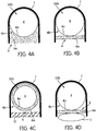
- Fig. 4A shows the cross section of the illumination portion (52a) of the illuminating instrument (1) in Fig. 1 , taken along the line A-A in Fig. 3 .
- the illumination portion (52a) has a groove (52b) on the surface of the housing (5).
- the optical fiber (4) is circumferentially arranged in the groove (52b).
- the groove (52b) matches the shape of the optical fiber (4). As shown in Fig.
- the optical fiber (4) in the illumination portion (52a) has a diffusing region (4a) for diffusing the electromagnetic radiation to the outside of the optical fiber (4) through the circumferential surface (4b).
- the diffusing region (4a) extends over the complete illumination portion (52a).
- the illumination portion (52a) has a reflecting surface (7).
- the diffusion region (4a) of the optical fiber (4) has a structure adapted to scatter the electromagnetic radiation to the outside.
- the structure comprises voids and particles.
- the electromagnetic radiation source (3) is an LED which is adapted to emit blue light.
- the blue light emitting LED has no phosphor coating to prevent overheating inside the grip portion (51). Alternatively, an LED which emits violet light may be used. As shown in Fig.
- a conversion means (6) is supported by the housing (5) and arranged between the diffusing region (4a) and the body part for converting the electromagnetic radiation into visible light for illuminating the body part.
- the conversions means (6) has a conversion material (6a) that is directly arranged onto the respective diffusing region (4a).
- the conversion material (6a) includes phosphor.
- Fig. 4B to Fig. 4C show alternative versions of the embodiment.
- the conversion material (6a) is arranged as a thick layer on the respective diffusing region (4a).
- the conversion material (6a) is coated on the diffusing region (4a).
- the illuminating instrument (1) has a dental drill device (8).
- the dental drill device (8) has a hub (8a) and a drill (8b) supported by the hub (8a).
- the head portion (52) supports the hub (8a).
- the illumination portion (52a) is in the head portion (52) around the hub (8a).
- the illuminating instrument (1) may be provided with a dental spray device, a dental scaler device, and/or a camera.
Abstract
The present invention relates to an illuminating instrument (1) for diagnostics, therapy or surgery of a body part, comprising: an optical fiber (4) for transmitting electromagnetic radiation from a electromagnetic radiation source (3) to the body part; a housing (5) which supports the optical fiber (4); characterized in that the optical fiber (4) is circumferentially arranged in an illumination portion (52a) in the housing (5) which is annular shaped and arranged to face the body part; the optical fiber (4) in the illumination portion (52a) has one or more diffusing regions (4a) for diffusing the electromagnetic radiation to the outside of the optical fiber (4) through the circumferential surface (4b), and a conversion means (6) is supported by the housing (5) and arranged between the diffusing regions (4a) and the body part for converting the electromagnetic radiation into visible light for illuminating the body part.
Description
- The present invention relates to illuminating instruments for diagnostics, surgery or therapy. The present invention more particularly relates to an illuminating dental instrument for drilling, scaling or spraying.
- A dental instrument for drilling, scaling or spraying generally needs an illumination for enabling the dentist to sufficiently clearly see the area being treated. Any sharp edges and color fringes in the illumination may lead to a fast fatigue of the dentist's eye. Furthermore, the shadows of the tool i.e., the drill, the scaler and the air/water jet can make it difficult for the dentist to work. Therefore, it is generally desired that a relatively large area can be intensively and uniformly illuminated. Due to its luminous efficiency, white LED technology is generally used for the illumination in dental instruments. Most white LEDs are manufactured as phosphor-conversion type LEDs which have a blue light emitting diode covered with yellow phosphor. The yellow phosphor emits white light upon excitation with the blue light. The LED technology is more efficient compared to incandescent lamps, however when used in environments where only a limited cooling is possible, the overheating leads to a reduction in the light output and the degradation of the LED.
-
DE10209194A1 discloses a handheld dental instrument for use with a detachable coupling device which has a light source for illuminating the object. The handheld dental instrument comprises an optical guide which is arranged to transmit the light from the light source to the body part. The handheld dental instrument has a housing which supports the optical guide. The housing is detachably attachable to the coupling device. - An objective of the present invention is to overcome the disadvantages of the prior art and provide an illuminating instrument for diagnostics, surgery or therapy with an improved illumination.
- This objective is achieved through the illuminating instrument for diagnostics, surgery or therapy as defined in
claim 1. The subject-matters of the dependent claims relate to further developments. - The present invention provides an illuminating instrument for diagnostics, therapy or surgery of a body part. The illuminating instrument comprises: at least one optical fiber for transmitting electromagnetic radiation from an electromagnetic radiation source to the body part; and a housing which supports the optical fiber. The optical fiber is circumferentially arranged in an illumination portion in the housing. The illumination portion is annular shaped and arranged to face the body part. The optical fiber in the illumination portion has one or more diffusing regions for diffusing the electromagnetic radiation to the outside of the optical fiber through the circumferential surface. The illuminating instrument further comprises a conversion means which is supported by the housing and arranged between the diffusing regions and the body part for converting the electromagnetic radiation into visible light for illuminating the body part.
- A major advantageous effect of the present invention is that a relatively large area can be intensely and uniformly illuminated without any shadows by the diffusing regions through the circumferential surface of the optical fiber which is circumferentially arranged in the annular shaped illumination portion of the illuminating instrument. Another major advantageous effect of the present invention is that the electromagnetic radiation source is prevented from overheating as the conversion means is arranged away from the electromagnetic radiation source, namely on the light exit side which is exposed by the diffusing regions. Thereby, a temperature dependent color shift in the illumination can be prevented. Thereby also the radiation output of the electromagnetic radiation source can be generally increased, and the illumination efficiency can be improved. The life of the electromagnetic radiation source can be prolonged, and the need for maintenance can be obviated or reduced. Since the overheating is suppressed, the electromagnetic radiation source may be safely operated even at higher radiation output levels to attain a more intense illumination. Furthermore, due to the suppression of the overheating, the illuminating instrument can be more safely and comfortably held by the user during the applications. For instance, the user's hand can be prevented from sweating.
- According to an embodiment of the present invention, the illuminating instrument is preferably adapted for use with a coupling device which has an electromagnetic radiation source, for instance an LED or a laser diode without a conversion means such as phosphor or the like. The coupling device is preferably detachably attachable to the housing. Alternatively, the coupling device may be an integral part of the illuminating instrument. The coupling device preferably has a hose including at least an electric wiring for connection to an electric power supply for powering the electromagnetic radiation source. In this embodiment, the coupling device and the illuminating instrument constitute an illuminating system. Alternatively, the coupling device may be battery driven. The battery may be exchangeable and/or rechargeable through a charging adapter. Alternatively, the hose of the coupling device may have another optical fiber for transmitting the electromagnetic radiation to the illuminating instrument.
- According to an embodiment of the present invention, the diffusing region preferably has a size and shape which matches the geometry of the area to be illuminated. The diffusing region preferably extends over the entire illumination portion. Alternatively, a plurality of identical diffusing regions are arranged at regular separations along the annular shaped illumination portion. Alternatively, the diffusing regions may be arranged at irregular separations along the annular shaped illumination portion.
- According to an embodiment of the present invention, the optical fiber is preferably arranged into a groove which is formed into the surface of the housing. The groove is preferably provided in a size and shape that matches the optical fiber. The cross section of the groove is preferably parabolic to attain uniform illumination towards the body part. However, the groove may have various cross sections. For instance, the cross section is alternatively u-shaped. The depth of the groove is preferably slightly larger than the diameter of the optical fiber to provide space for filling a translucent sealing substance which has preferably a light diffusing characteristic.
- According to an embodiment of the present invention, the illumination portion preferably has a reflective surface to reflect the light towards the body part. The reflective surface is obtained by polishing the groove. Alternatively, the groove may be coated with a reflective substance. Alternatively, a separate annular shaped optical reflective surface is arranged into the groove behind the optical fiber.
- According to an embodiment of the present invention, one or more lenses are preferably arranged between the diffusing regions and the body part respectively. The lens is preferably annular shaped. Thereby the size and shape of the illumination can be adjusted to the application.
- According to alternative embodiments of the present invention, the illuminating instrument is preferably provided with a dental device such as dental spray device, a dental drill device, or a dental scaler device, or a camera for medical imaging. The camera may be sensitive to visible light, UV light or IR light. In these embodiments, the hose of the coupling device is preferably provided, in addition to the electric wiring, with supply lines for pressurized air and/or pressurized liquid. The dental spray device has nozzles for ejecting the pressurized air and the pressurized liquid. The dental drill device has a hub and a drill supported by the hub. The dental drill device is preferably driven by a turbine. Alternatively, an electric motor may be used. The dental scaler device has a tip for scaling. The housing preferably has a grip portion and a head portion for supporting the respective dental device and/or the camera. The annular-shaped illumination portion is in the head portion around the camera, the nozzles, or the drill or the scaling tip to attain shadowless uniform illumination.
- According to an embodiment of the present invention, the optical fiber preferably extends, inside the housing, from the grip portion to the illumination portion in the head portion.
- According to an embodiment of the present invention, the diffusion region of the optical fiber preferably has at least a structure adapted to scatter the electromagnetic radiation to the outside. The structure includes voids and/or particles formed in the optical fiber. The structures are preferably formed into the core and/or the cladding of the optical fiber. The optical fiber in the illumination portion is provided without any protective coatings to enable the diffusion of the electromagnetic radiation through the circumferential surface.
- According to alternative embodiments of the present invention, the electromagnetic radiation source is preferably adapted to user selectively emit blue light, violet light, or infrared light. The conversion means has a conversion material, preferably phosphor and/or lanthanide doped nanoparticles. The lanthanide doped nanoparticles convert near infrared light into near ultraviolet light which can be used for bioimaging. The conversion material is preferably coated onto the optical fiber at the respective diffusing region. Alternatively, the conversions material is arranged near the respective diffusing region. Different diffusing regions may have different compositions of the conversion material for illumination and/or medical imaging.
- In the subsequent description, the present invention will be described in more detail by using exemplary embodiments and by referring to the drawings, wherein
-
Fig. 1 - is a schematic perspective view of an illuminating system having the illuminating instrument and the coupling device according to an embodiment of the present invention; -
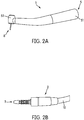
Fig. 2A - is a schematic perspective view of the illuminating instrument inFig. 1 ; -
Fig. 2B - is a schematic perspective view of the coupling device inFig. 1 ; -
Fig. 3 - is a schematic bottom view of the head portion of the illuminating instrument inFig. 1 ; -
Fig. 4A - is a schematic cross sectional view of the head portion of the illuminating instrument inFig. 1 , taken along the line A-A inFig. 3 ; -
Fig. 4B - is a schematic cross sectional view of the head portion of the illuminating instrument according to another embodiment, taken along the line A-A inFig. 3 ; -
Fig. 4C - is a schematic cross sectional view of the head portion of the illuminating instrument according to another embodiment, taken along the line A-A inFig. 3 ; -
Fig. 4D - is a schematic cross sectional view of the head portion of the illuminating instrument according to another embodiment, taken along the line A-A inFig. 3 ; -
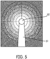
Fig. 5 - is a schematic partial top view of the illuminating instrument showing the light distribution of the illumination. - The reference numbers shown in the drawings denote the elements as listed below and will be referred to in the subsequent description of the exemplary embodiments.
- 1. Illuminating instrument
- 2. Coupling device
- 3. E.M. Radiation source
- 4. Optical fiber
- 4a. Diffusing regions
- 4b. Circumferential surface
- 5. Housing
- 51. Grip portion
- 52. Head portion
- 52a. Illumination portion
- 52b. Groove
- 6. Conversion means
6a. Conversion material - 7. Reflective surface
- 8. Dental drill device
- 8a. Hub
- 8b. Drill
- 9. Illuminating system
- 10. Hose
- 11. Lens
- 12. Diffusor
-
Fig. 1 shows an illuminating system (9) according to an embodiment of the present invention. The illuminating system (9) has an illuminating instrument (1) and a coupling device (2). The illuminating instrument (1) is suitable for diagnostics, therapy or surgery of a body part. The illuminating instrument (1) is adapted for use with the coupling device (2). As shown inFig. 2A and Fig. 2B , the illuminating instrument (1) and the coupling device (2) are detachably attachable. The housing (5) of the illuminating instrument (1) can be detachably attached to the coupling device (2). As shown inFig. 2B , the coupling device (2) has an electromagnetic radiation source (3) for generating electromagnetic radiation. The coupling device (2) has a hose (10) for supplying electric power to the electromagnetic radiation source (3). As shown inFig. 2A , the housing (5) has a grip portion (51) and a head portion (52). As shown inFig. 3 , the head portion (52) has an illumination portion (52a). The illuminating instrument (1) has an optical fiber (4) for transmitting the electromagnetic radiation from the electromagnetic radiation source (3) to the illumination portion (52a) which faces the body part. The optical fiber (4) is supported by the housing (5) of the illuminating instrument (1). The optical fiber (4) extends, inside the housing (5), from the grip portion (51) to the illumination portion (52a) of the head portion (52). As shown inFig. 3 , the optical fiber (4) is circumferentially arranged in the illumination portion (52a) of the housing (5). The illumination portion (52a) is annular shaped and arranged to face the body part.Fig. 4A shows the cross section of the illumination portion (52a) of the illuminating instrument (1) inFig. 1 , taken along the line A-A inFig. 3 . The illumination portion (52a) has a groove (52b) on the surface of the housing (5). The optical fiber (4) is circumferentially arranged in the groove (52b). The groove (52b) matches the shape of the optical fiber (4). As shown inFig. 4A , the optical fiber (4) in the illumination portion (52a) has a diffusing region (4a) for diffusing the electromagnetic radiation to the outside of the optical fiber (4) through the circumferential surface (4b). The diffusing region (4a) extends over the complete illumination portion (52a). The illumination portion (52a) has a reflecting surface (7). The diffusion region (4a) of the optical fiber (4) has a structure adapted to scatter the electromagnetic radiation to the outside. The structure comprises voids and particles. The electromagnetic radiation source (3) is an LED which is adapted to emit blue light. The blue light emitting LED has no phosphor coating to prevent overheating inside the grip portion (51). Alternatively, an LED which emits violet light may be used. As shown inFig. 4A , a conversion means (6) is supported by the housing (5) and arranged between the diffusing region (4a) and the body part for converting the electromagnetic radiation into visible light for illuminating the body part. As shown inFig. 4A , the conversions means (6) has a conversion material (6a) that is directly arranged onto the respective diffusing region (4a). The conversion material (6a) includes phosphor.Fig. 4B to Fig. 4C show alternative versions of the embodiment. As shown inFig. 4B and Fig. 4D , the conversion material (6a) is arranged as a thick layer on the respective diffusing region (4a). As shown inFig. 4C , the conversion material (6a) is coated on the diffusing region (4a). As shown in 4C, an additional diffusor (12) is arranged between the diffusing region (4a) and the body part. As shown in 4D, a lens (11) is arranged between the diffusing region (4a) and the body part. The gaps in the groove (52b) are filled with a heat resistant transparent sealing material. As shown inFig. 1 , the illuminating instrument (1) has a dental drill device (8). The dental drill device (8) has a hub (8a) and a drill (8b) supported by the hub (8a). The head portion (52) supports the hub (8a). As shown inFig. 3 , the illumination portion (52a) is in the head portion (52) around the hub (8a). Alternatively, the illuminating instrument (1) may be provided with a dental spray device, a dental scaler device, and/or a camera.
Claims (15)
- An illuminating instrument (1) for diagnostics, therapy or surgery of a body part, comprising:at least one optical fiber (4) for transmitting electromagnetic radiation from an electromagnetic radiation source (3) to the body part; anda housing (5) which supports the optical fiber (4);characterized in thatthe optical fiber (4) is circumferentially arranged in an illumination portion (52a) in the housing (5) which is annular shaped and arranged to face the body part;the optical fiber (4) in the illumination portion (52a) has one or more diffusing regions (4a) for diffusing the electromagnetic radiation to the outside of the optical fiber (4) through the circumferential surface (4b), anda conversion means (6) is supported by the housing (5) and arranged between the diffusing regions (4a) and the body part for converting the electromagnetic radiation into visible light for illuminating the body part.
- The illuminating instrument (1) according to claim 1, characterized in that the illuminating instrument (1) is adapted for use with a coupling device (2) having the electromagnetic radiation source (3) for generating electromagnetic radiation; wherein the housing (5) is detachably attachable to the coupling device (2).
- The illuminating instrument (1) according to claim 1 or 2, characterized in that the diffusing region (4a) extends over the complete illumination portion (52a).
- The illuminating instrument (1) according to any one of claims 1 to 3, characterized in that the illumination portion (52a) comprises a groove (52b) on the surface of the housing (5), wherein the groove (52b) matches the shape of the optical fiber (4).
- The illuminating instrument (1) according to any of claims 1 to 4, characterized in that the illumination portion (52a) comprises a reflecting surface (7).
- The illuminating instrument (1) according to any one of claims 1 to 5, characterized by further comprising one or more lenses (11) arranged between the diffusing regions (4a) and the body part respectively.
- The illuminating instrument (1) according to any one of claims 1 to 6, characterized by further comprising a dental spray device having one or more nozzles, wherein the housing (5) has a grip portion (51) and a head portion (52) for supporting the dental spray device, and wherein the illumination portion (52a) is in the head portion (52) around the nozzles of the dental spray device.
- The illuminating instrument (1) according to any one of claims 1 to 6, characterized by further comprising a dental drill device (8) having a hub (8a) and a drill (8b) supported by the hub (8a), wherein the housing (5) has a grip portion (51) and a head portion (52) for supporting the hub (8a), wherein the illumination portion (52a) is in the head portion (52) around the hub (8a).
- The illuminating instrument (1) according to any one of claims 1 to 6, characterized by further comprising a dental scaler device having a tip, wherein the housing (5) has a grip portion (51) and a head portion (52) for supporting the tip, wherein the illumination portion (52a) is in the head portion (52) around the tip.
- The illuminating instrument (1) according to any one of claims 7 to 9, characterized in that the optical fiber (4) extends, inside the housing (5), from the grip portion (51) to the illumination portion (52a) of the head portion (52).
- The illuminating instrument (1) according to any one of claims 1 to 10, characterized in that one or more diffusion regions (4a) of the optical fiber (4) each has at least a structure adapted to scatter the electromagnetic radiation to the outside, wherein the structure comprises voids and/or particles.
- The illuminating instrument (1) according to any one of claims 1 to 11, characterized in that the electromagnetic radiation source (3) is adapted to user selectively emit blue light or violet light or infrared light.
- The illuminating instrument (1) according to any one of claims 1 to 12, characterized in that the conversions means (6) comprises conversion material (6a) that is coated onto the respective diffusing region (4a) or arranged separately in close proximity of the respective diffusing region (4a).
- The illuminating instrument (1) according to claim 13, characterized in that the conversion material (6a) comprises phosphor and/or lanthanide doped nanoparticles.
- An illuminating system (9) characterized by further comprising: the coupling device (2) and the illuminating instrument (1) according to any one of claims 1 to 14; and a hose (10) for supplying the coupling device (2) at least with electric power.
Priority Applications (6)
| Application Number | Priority Date | Filing Date | Title |
|---|---|---|---|
| EP19177390.2A EP3744288A1 (en) | 2019-05-29 | 2019-05-29 | Illuminating instrument for diagnostics, surgery or therapy |
| EP20734464.9A EP3975915B1 (en) | 2019-05-29 | 2020-05-26 | Illuminating instrument for diagnostics, surgery or therapy |
| US17/614,621 US20220226071A1 (en) | 2019-05-29 | 2020-05-26 | Illuminating instrument for diagnostics, surgery or therapy |
| PCT/EP2020/064495 WO2020239719A1 (en) | 2019-05-29 | 2020-05-26 | Illuminating instrument for diagnostics, surgery or therapy |
| JP2021539623A JP2022535311A (en) | 2019-05-29 | 2020-05-26 | Diagnostic, surgical or therapeutic luminaires |
| CN202080007652.1A CN113329677A (en) | 2019-05-29 | 2020-05-26 | Lighting apparatus for diagnosis, surgery or treatment |
Applications Claiming Priority (1)
| Application Number | Priority Date | Filing Date | Title |
|---|---|---|---|
| EP19177390.2A EP3744288A1 (en) | 2019-05-29 | 2019-05-29 | Illuminating instrument for diagnostics, surgery or therapy |
Publications (1)
| Publication Number | Publication Date |
|---|---|
| EP3744288A1 true EP3744288A1 (en) | 2020-12-02 |
Family
ID=66676437
Family Applications (2)
| Application Number | Title | Priority Date | Filing Date |
|---|---|---|---|
| EP19177390.2A Withdrawn EP3744288A1 (en) | 2019-05-29 | 2019-05-29 | Illuminating instrument for diagnostics, surgery or therapy |
| EP20734464.9A Active EP3975915B1 (en) | 2019-05-29 | 2020-05-26 | Illuminating instrument for diagnostics, surgery or therapy |
Family Applications After (1)
| Application Number | Title | Priority Date | Filing Date |
|---|---|---|---|
| EP20734464.9A Active EP3975915B1 (en) | 2019-05-29 | 2020-05-26 | Illuminating instrument for diagnostics, surgery or therapy |
Country Status (5)
| Country | Link |
|---|---|
| US (1) | US20220226071A1 (en) |
| EP (2) | EP3744288A1 (en) |
| JP (1) | JP2022535311A (en) |
| CN (1) | CN113329677A (en) |
| WO (1) | WO2020239719A1 (en) |
Citations (6)
| Publication number | Priority date | Publication date | Assignee | Title |
|---|---|---|---|---|
| DE10209194A1 (en) | 2002-03-04 | 2003-10-02 | Sirona Dental Systems Gmbh | Dental hand instrument has functional unit with headpiece and handgrip coupled and incorporating feed lines for air, water, electric current, light and/or electrical signals |
| US20060171693A1 (en) * | 2005-01-28 | 2006-08-03 | Stryker Corporation | Endoscope with integrated light source |
| US20070121786A1 (en) * | 2003-12-08 | 2007-05-31 | J. Morita Manufacturing Corporation | Dental diagnostic and treatment apparatus |
| US20130137923A1 (en) * | 2011-04-07 | 2013-05-30 | Olympus Corporation | Endoscope and illumination apparatus for endoscope |
| US20140134568A1 (en) * | 2011-07-19 | 2014-05-15 | W&H Dentalwerk Burmoos Gmbh | Lighting device for a medical or dental instrument |
| US20160103312A1 (en) * | 2013-07-09 | 2016-04-14 | Olympus Corporation | Illumination device |
-
2019
- 2019-05-29 EP EP19177390.2A patent/EP3744288A1/en not_active Withdrawn
-
2020
- 2020-05-26 WO PCT/EP2020/064495 patent/WO2020239719A1/en unknown
- 2020-05-26 CN CN202080007652.1A patent/CN113329677A/en active Pending
- 2020-05-26 JP JP2021539623A patent/JP2022535311A/en active Pending
- 2020-05-26 EP EP20734464.9A patent/EP3975915B1/en active Active
- 2020-05-26 US US17/614,621 patent/US20220226071A1/en active Pending
Patent Citations (6)
| Publication number | Priority date | Publication date | Assignee | Title |
|---|---|---|---|---|
| DE10209194A1 (en) | 2002-03-04 | 2003-10-02 | Sirona Dental Systems Gmbh | Dental hand instrument has functional unit with headpiece and handgrip coupled and incorporating feed lines for air, water, electric current, light and/or electrical signals |
| US20070121786A1 (en) * | 2003-12-08 | 2007-05-31 | J. Morita Manufacturing Corporation | Dental diagnostic and treatment apparatus |
| US20060171693A1 (en) * | 2005-01-28 | 2006-08-03 | Stryker Corporation | Endoscope with integrated light source |
| US20130137923A1 (en) * | 2011-04-07 | 2013-05-30 | Olympus Corporation | Endoscope and illumination apparatus for endoscope |
| US20140134568A1 (en) * | 2011-07-19 | 2014-05-15 | W&H Dentalwerk Burmoos Gmbh | Lighting device for a medical or dental instrument |
| US20160103312A1 (en) * | 2013-07-09 | 2016-04-14 | Olympus Corporation | Illumination device |
Also Published As
| Publication number | Publication date |
|---|---|
| US20220226071A1 (en) | 2022-07-21 |
| WO2020239719A1 (en) | 2020-12-03 |
| CN113329677A (en) | 2021-08-31 |
| EP3975915A1 (en) | 2022-04-06 |
| JP2022535311A (en) | 2022-08-08 |
| EP3975915B1 (en) | 2023-05-31 |
Similar Documents
| Publication | Publication Date | Title |
|---|---|---|
| EP1388326B1 (en) | Curing light instrument | |
| JP4056930B2 (en) | Medical light irradiation device | |
| KR100643516B1 (en) | Medical irradiation apparatus | |
| JP2008508034A (en) | Contra-angle rotating handpiece with tactile feedback tip ferrule | |
| US20030215766A1 (en) | Light emitting systems and kits that include a light emitting device and one or more removable lenses | |
| US20130317295A1 (en) | Light assembly for remote visual inspection apparatus | |
| US10076390B2 (en) | Light mixture | |
| JP2007537776A (en) | Irradiation apparatus and related method | |
| IT8922495A1 (en) | LIGHT RADIATOR WITH SCREW CONNECTION TO THE LIGHT SOURCE AND MULTIDIRECTIONAL EMISSION. | |
| US20130344456A1 (en) | Low Pass Filter Attachments for Use with Dental Curing Lights | |
| JP2007020937A (en) | Endoscope apparatus | |
| US20030147258A1 (en) | Curing light with plurality of LEDs and corrresponding lenses configured to focus light | |
| JP2000316874A (en) | Dental instrument with illuminating mechanism | |
| US20090176186A1 (en) | Air/light dental device | |
| US20080256729A1 (en) | Teeth Whitening Toothbrush | |
| WO2000013608A1 (en) | Irradiation apparatus for light curing of composites, in particular for dental use | |
| US20030148242A1 (en) | Lightweight hand held dental curing device | |
| EP3975915B1 (en) | Illuminating instrument for diagnostics, surgery or therapy | |
| GB2420172A (en) | Lamp with air cooling and heat sink | |
| JP2002200100A (en) | Projector | |
| JP2006049283A (en) | Luminous body | |
| WO2003065920A1 (en) | Lightweight hand held dental curing device | |
| JP3194328U (en) | Luminaire having a diffusion part on a peripheral surface of a light guide part | |
| JP3565803B2 (en) | Scaler | |
| RU112338U1 (en) | LIGHTING DEVICE |
Legal Events
| Date | Code | Title | Description |
|---|---|---|---|
| PUAI | Public reference made under article 153(3) epc to a published international application that has entered the european phase |
Free format text: ORIGINAL CODE: 0009012 |
|
| STAA | Information on the status of an ep patent application or granted ep patent |
Free format text: STATUS: THE APPLICATION HAS BEEN PUBLISHED |
|
| AK | Designated contracting states |
Kind code of ref document: A1 Designated state(s): AL AT BE BG CH CY CZ DE DK EE ES FI FR GB GR HR HU IE IS IT LI LT LU LV MC MK MT NL NO PL PT RO RS SE SI SK SM TR |
|
| AX | Request for extension of the european patent |
Extension state: BA ME |
|
| STAA | Information on the status of an ep patent application or granted ep patent |
Free format text: STATUS: THE APPLICATION HAS BEEN WITHDRAWN |
|
| 18W | Application withdrawn |
Effective date: 20210609 |