EP3744054B1 - Zeitempfindliche vernetzung - Google Patents
Zeitempfindliche vernetzung Download PDFInfo
- Publication number
- EP3744054B1 EP3744054B1 EP18701470.9A EP18701470A EP3744054B1 EP 3744054 B1 EP3744054 B1 EP 3744054B1 EP 18701470 A EP18701470 A EP 18701470A EP 3744054 B1 EP3744054 B1 EP 3744054B1
- Authority
- EP
- European Patent Office
- Prior art keywords
- gate
- entry
- time
- entries
- gate control
- Prior art date
- Legal status (The legal status is an assumption and is not a legal conclusion. Google has not performed a legal analysis and makes no representation as to the accuracy of the status listed.)
- Active
Links
Images


Classifications
-
- H—ELECTRICITY
- H04—ELECTRIC COMMUNICATION TECHNIQUE
- H04L—TRANSMISSION OF DIGITAL INFORMATION, e.g. TELEGRAPHIC COMMUNICATION
- H04L47/00—Traffic control in data switching networks
- H04L47/10—Flow control; Congestion control
- H04L47/22—Traffic shaping
-
- H—ELECTRICITY
- H04—ELECTRIC COMMUNICATION TECHNIQUE
- H04L—TRANSMISSION OF DIGITAL INFORMATION, e.g. TELEGRAPHIC COMMUNICATION
- H04L12/00—Data switching networks
- H04L12/28—Data switching networks characterised by path configuration, e.g. LAN [Local Area Networks] or WAN [Wide Area Networks]
- H04L12/40—Bus networks
- H04L12/40143—Bus networks involving priority mechanisms
-
- H—ELECTRICITY
- H04—ELECTRIC COMMUNICATION TECHNIQUE
- H04L—TRANSMISSION OF DIGITAL INFORMATION, e.g. TELEGRAPHIC COMMUNICATION
- H04L47/00—Traffic control in data switching networks
- H04L47/10—Flow control; Congestion control
- H04L47/34—Flow control; Congestion control ensuring sequence integrity, e.g. using sequence numbers
-
- H—ELECTRICITY
- H04—ELECTRIC COMMUNICATION TECHNIQUE
- H04L—TRANSMISSION OF DIGITAL INFORMATION, e.g. TELEGRAPHIC COMMUNICATION
- H04L47/00—Traffic control in data switching networks
- H04L47/50—Queue scheduling
- H04L47/56—Queue scheduling implementing delay-aware scheduling
-
- H—ELECTRICITY
- H04—ELECTRIC COMMUNICATION TECHNIQUE
- H04L—TRANSMISSION OF DIGITAL INFORMATION, e.g. TELEGRAPHIC COMMUNICATION
- H04L47/00—Traffic control in data switching networks
- H04L47/50—Queue scheduling
- H04L47/62—Queue scheduling characterised by scheduling criteria
- H04L47/622—Queue service order
-
- H—ELECTRICITY
- H04—ELECTRIC COMMUNICATION TECHNIQUE
- H04L—TRANSMISSION OF DIGITAL INFORMATION, e.g. TELEGRAPHIC COMMUNICATION
- H04L67/00—Network arrangements or protocols for supporting network services or applications
- H04L67/01—Protocols
- H04L67/12—Protocols specially adapted for proprietary or special-purpose networking environments, e.g. medical networks, sensor networks, networks in vehicles or remote metering networks
-
- H—ELECTRICITY
- H04—ELECTRIC COMMUNICATION TECHNIQUE
- H04L—TRANSMISSION OF DIGITAL INFORMATION, e.g. TELEGRAPHIC COMMUNICATION
- H04L12/00—Data switching networks
- H04L12/28—Data switching networks characterised by path configuration, e.g. LAN [Local Area Networks] or WAN [Wide Area Networks]
- H04L12/40—Bus networks
- H04L2012/4026—Bus for use in automation systems
Definitions
- the present invention relates to a time-sensitive networking.
- Time-sensitive networking is a set of standards which define mechanisms for transmitting time-sensitive data over Ethernet networks.
- IEEE 802.1 Qbv-2015 entitled “Enhancements for Scheduled Traffic” specifies time-aware queue-draining procedures that enable nodes, such as bridges and end stations, to schedule transmission of frames based on IEEE 802.1AS timing, according to a common time in the whole network.
- Virtual Local Area Network (VLAN) priority values are used to enable simultaneous support of scheduled traffic, credit-based shaper (CBS) traffic and other bridged traffic over Local Area Networks (LANs). It defines a scheduling scheme involving reservation of time windows for different types of streams.
- FIG 1 schematically illustrates transmission selection using a time-aware shaper (TAS) defined in IEEE 802.1 Qbv-2015 for a set of eight queues having different traffic classes.
- TAS time-aware shaper
- the transmission gates (herein simply referred to as "gates") are used to control the transmission of frames in each traffic class: when a gate is open, frames in a traffic class can be transmitted and when the gate is closed, frames in that traffic class are blocked.
- the gates are controlled by a programmable common gate control list which specifies which traffic queue is permitted to transmit at a given point in time within a cycle.
- FIG. 2 schematically illustrates a hardware implementation of an Ethernet controller which includes queues, gates controlled by a gate control list in accordance with IEEE 802.1 Qbv-2015, credit-based shaping logic and prioritised transmission selection logic.
- the gate control list and corresponding logic for controlling gate list execution can be implemented using registers and hardware logic.
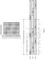
- Figure 3 illustrates a very simple example of gate control involving three gates whose individual and collective repetition patterns are straightforward.
- Gate repetition is the time after which behaviour of a gate repeats.
- TAS cycle time is the smallest multiple of all gate individual repetition rates.
- Gate 0 is open for time t1, is closed for times t2 and t3, open for time t4, and closed for times t5 and t6.
- Gate 1 is closed for time t1, open for time t2, closed for times t3 and t4, open for time t5 and closed for time t6.
- Gate 3 open for times t1 and t2, open for time t3, closed during time t4 and open for times t5 and t6.
- the common gate control list has six entries.
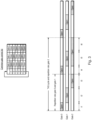
- Figure 4 illustrates a more complicated (but still quite simple) example of gate control involving three gates.
- the example still involves the same number of gate-open and gate-close events as that shown in Figure 3 , but where the events are not aligned so well.
- the common gate control list now has eleven entries.
- the lists can still become very long. For example, if a frame size is 1 ms and repetition time is either 1 ms and 20 ms, then this may require 40 entries in the table ( i.e., 2 ⁇ lowest common multiple of 1 and 20). If an application requires repetition rates with inconvenient periods, such as 1 ms, 8 ms, and 15 ms, then 240 entries may be required ( i.e., 2 ⁇ lowest common multiple of 1, 8 and 15).
- a time-aware shaper is defined such that a gate can only transmit a frame associated for its queue if there is sufficient time, i.e., time between a gate-start event and a gate-end event. This imposes a requirement for the gate to know the timing of the gate-end event to calculate whether is sufficient time available to transmit the entirety of the frame before the next gate-close event.
- the common gate control list is not particularly suited to achieve this.
- a hardware-implemented time-aware shaper should be able to handle many patterns of gate-open and gate-close events as possible involving a wide range of overlaps and so allow the time-aware shaper to be used in as many applications as possible without application-specific modification or adaptation.
- TSN Time-Sensitive Networking
- FWC Frequency-Sensitive Networking
- GCL Gate-Control List
- the GCLs can define a deterministic schedule of when to forward critical frames on links.
- the hyperperiod is the Least Common Multiple (LCM) of all the flow periods.
- a network device for time-sensitive networking comprising a set of queues and a time-aware shaper which comprises a set of transmission gates, a set of gate controllers and gate control instructions.
- the gate control instructions comprise a set of individual queue gate lists, each individual queue gate list configured to control a respective gate, each gate corresponding to a queue in the set of queues.
- Each individual gate control list comprising: a sequence of entries beginning with an initial entry (10i) set to empty, and followed by a first entry for the respective gate; each subsequent entry comprising: a control field which specifies a gate state of either open or closed for the respective gate; and an accumulated duration of time comprising one or more timeslots for the gate state, wherein, at least one entry in the sequence of entries comprises a plurality of timeslots, and wherein when the first and last gate states are the same, each entry in the sequence of entries is moved by one entry position such that the first entry becomes the initial entry and the duration of the last entry is modified by adding the duration that was specified in the first entry; and each gate controller of the set of gate controllers is configured to read an individual gate control list, to generate a gate control signal and to issue the gate control signal to a respective gate, wherein each gate controller is configured, in a first cycle, to read each entry in the sequence of entries starting from the initial entry and to toggle the state of the gate in response to reading each entry and, in a second, subsequent
- An entry in the sequence of entries may include a control field which indicates end of list.
- a registry may be provided with includes the number of entries (or "length of list").
- the network device may further comprise configuration data associated with each individual queue gate list.
- the individual queue gate list and the configuration data may be stored in the same location, for example, a special function register or memory.
- the network device may further comprise a data handler for allocating data to the set of queues.
- the network device may further comprise a media access controller.
- the network device may further comprise transmission selection logic.
- the network device is preferably an Ethernet controller.
- the network device is preferably implemented in hardware.
- a monolithic integrated circuit comprising the network device.
- the monolithic integrated circuit may further comprise at least one central processing unit.
- the monolithic integrated circuit may be a microcontroller or a system-on-a-chip (SoC).
- the network device may be a peripheral module of a microcontroller or SoC.
- the monolithic integrated circuit may further comprise random-access memory.
- the monolithic integrated circuit may further comprise a routing engine and so provide, for example, a bridge (or "switch").
- the monolithic integrated circuit may further comprise a physical layer transceiver ( i.e ., PHY).
- the monolithic integrated circuit may further comprise an interface to an external ( i.e ., off-chip) physical layer transceiver.
- the transceiver may comprise a media-independent interface (Mil) module.
- an end station comprising the network device of the first aspect of the invention or the monolithic integrated circuit of second aspect of the invention.
- a switch or bridge comprising the network device of the first aspect of the invention or the monolithic integrated circuit of second aspect of the invention.
- a network comprising a bus system and at least one network device of the first aspect of the invention, at least one monolithic integrated circuit of the second aspect of the invention, at least one end station of the third aspect of the invention and/or at least one switch of the fourth aspect of the invention in wired communication with the bus system.
- a motor vehicle comprising at least one network device of the first aspect of the invention, at least one monolithic integrated circuit of the second aspect of the invention, at least one end station of the third aspect of the invention and/or at least one switch of the fourth aspect of the invention.
- the motor vehicle may be a motorcycle, an automobile (sometimes referred to as a "car"), a minibus, a bus, a truck or lorry.
- the motor vehicle may be powered by an internal combustion engine and/or one or more electric motors.
- a seventh aspect of the present invention there is provided a system comprising at least one network device of the first aspect of the invention, at least one monolithic integrated circuit of the second aspect of the invention, at least one end station of the third aspect of the invention and/or at least one switch of the fourth aspect of the invention.
- the system may be an industrial system, such as a plant.
- the plant may include one or more robots and/or controllers for the robots connected by a time-sensitive network.
- the method comprises receiving data describing operation of a set of gates (or "gate operation database"), converting the data into a set of individual gate control lists each individual gate control list configured to control a respective gate and which comprises a sequence of entries (10) beginning with an initial entry (10i) set to empty, and followed by a first entry, each subsequent entry comprising a control field (12) which specifies a gate state of either open or closed for the respective gate, and an accumulated duration of time comprising one or more timeslots for the gate state, wherein, at least one entry in the sequence of entries comprises a plurality of timeslots, and wherein when the first and last gate states are the same, each entry in the sequence of entries is moved forward by one entry position such that the first entry becomes the initial entry and the duration of the last entry is modified by adding the duration that was specified in the first entry; writing the set of individual gate control lists into memory or set of registers; in a first cycle, reading each entry in the sequence of entries starting from the initial
- a ninth aspect of the present invention there is provided a computer program which, when executed by a processor, causes the processor to perform the method of seventh aspect of the present invention.
- a computer program product comprising a computer-readable medium (for example, a non-transitory computer readable medium) carrying or storing the computer program of the ninth aspect of the present invention.
- the method is preferably a hardware-implemented method.
- a hardware-implemented network device 1 supporting time-sensitive networking (TSN) in accordance with IEEE 802.1 Qbv -2015 is shown.
- the device 1 is comprises a set of queues 2 and a time-aware shaper 3 which complies with IEEE 802.1 Qbv -2015.
- the time-aware shaper 3 includes, among other things, a set of transmission gates 4 and gate control instructions 5.
- the gate control instructions 5 control transmission of data frames 6 by the transmission gates 4.
- the time-aware shaper 3 allows transmission of data frames 6 from a queue 2 to be scheduled.
- the gate control instructions 5 comprises a set of individual gate control lists 7 (or "queue gate lists” or “QGLs”), each individual gate control list 7 arranged to control a respective gate 4.
- Each individual gate control list 7 includes a series or sequence of one or more entries 10 which may specify an open time or close time 11 ( Figure 11 ).
- each time 11 indicates the time (or "duration") for which a gate is open or closed.
- Each individual gate control list 7 can have a different number of entries 10. In other words, the individual gate control lists 7 do not need to have the same number of entries 10.
- Each individual gate control list 7 can be small (for example, containing between 1 to 16 entries) since each list 7 need only handle repetition of one gate 4. Moreover, a set of individual gate control lists 7 can handle gates 4 whose open times are not well aligned, for example, involving overlapping open gate times, where the identity of the overlapping gates can vary throughout the cycle and the overlapping open gate times vary in duration. Furthermore, control using individual gate control lists 7 can be simpler and quicker than using a common gate control list since open and close times are predetermined and can be simply read out from each list 7, rather than being computed on-the-fly during operation.
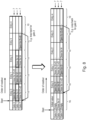
- Figure 6 also shows a common gate control list for providing gate control and a set of three individual gate control lists 7 for achieving the same outcome as the common gate control list.
- An individual gate control list 7 for gate 0 includes two entries 10, namely a first entry 10 indicating that the gate 0 should be open for time t1 and a second entry 10 indicating that the gate should be closed for time t2+t3.
- An individual gate control list 7 for gate 1 includes three entries 10, namely a first entry 10 indicating that the gate 1 should be closed for time t1 and a second entry 10 indicating that the gate should be open for time t2 and a third entry 10 indicating that the gate should be closed for time t3.
- An individual gate control list 7 for gate 2 includes four entries 10, namely a first entry 10 indicating that the gate 2 should be closed for time t1+t2 and a second entry 10 indicating that the gate should be open for time t3, a third entry 10 indicating that the gate should be closed for time t4 and a fourth entry 10 indicating that the gate should be open for time t5+t6.
- FIG. 7 a more complex example of time-aware shaper gate control is shown. This pattern of gate states is the same as that shown in Figure 4 .
- Figure 7 also shows a common gate control list for providing gate control and a set of three individual gate control lists 7 for achieving the same outcome as the common gate control list.
- An individual gate control list 7 for gate 0 includes two entries 10, namely a first entry 10 indicating that the gate 0 should be open for time t1+t2 and a second entry 10 indicating that the gate should be closed for time t3+t4+t5+t6.
- An individual gate control list 7 for gate 1 includes three entries, namely a first entry 10 indicating that the gate 1 should be closed for time t1 and a second entry 10 indicating that the gate should be closed for time t2+t3+t4 and a third entry 10 indicating that the gate should be closed for time t5+t6.
- An individual gate control list 7 for gate 2 includes four entries 10, namely a first entry 10 indicating that the gate 2 should be closed for time t1+t2+t3, a second entry 10 indicating that the gate should be open for time t4+t5, a third entry 10 indicating that the gate should be closed for time t6+t7+t8 and a fourth entry 10 indicating that the gate should be open for time t9+t10+t11.
- One approach to gate control is simply to go through an individual gate control list 7 and, having gone through the list, to start going through the list from the start of the list.
- this can interfere with toggling. It can result in inversion of gate state and so requires hardware and/or software to check the states of the first and last entries and, if necessary, to prevent toggling after the last entry or take other appropriate action.
- the individual gate control lists 7 can include an initial entry (or "one-time entry") 10 i which is read once when an individual gate control list 7 is read for the first time.
- the list 7 is adapted such that the first entry 10 becomes an initial entry 10 i and the duration of the last entry 10 is modified by adding the duration that was specified in the first entry 10.
- a first entry 10 indicates that gate 1 is open for t1 and a last entry 10 indicates that gate 1 is open for t3.
- the initial entry 10 i is set to indicate that gate 1 is closed for t1, then the following entries are shifted such that entry 1 becomes entry o, entry 2 becomes entry 1 and the last entry 10 is modified by adding the time t1, i.e., to become t1+t3.
- an integrated circuit 21 supporting time-sensitive networking is shown.
- the integrated circuit 21 takes the form of a microcontroller, system-on-a-chip or other similar microprocessor-based system.
- the integrated circuit 21 need not include a microprocessor and may, for example, include an interface to a microprocessor (not shown) on a different chip (not shown).
- the integrated circuit 21 includes a CPU sub-system 22 which includes at least one CPU 23, user RAM 24 (which may also be referred to as system RAM or simply RAM), and a TSN-compliant network device 1 in the form of an Ethernet controller interconnected by a bus system 26.
- the integrated circuit 21 may include a routing engine (not shown) for providing Ethernet switch functionality.
- the integrated circuit 21 may provide Ethernet end station functionality.
- the integrated circuit 21 may include other peripheral modules such as a timer, an interrupt controller and other types of communications controller.
- the integrated circuit 21 may also include physical layer (PHY) transceiver module(s) (not shown). In this case, however, external PHY transceiver IC (not shown) is used.
- PHY physical layer
- a CPU 23 loads and executes application software 28 for transforming time-aware shaper control data 29 into individual gate control list data 7.
- the control data 29 takes the form of management information base (MIB) and is stored, for example, in the user RAM 24.
- the user RAM 24 may also store data 6, for example in the form of frames, for transmission by the Ethernet controller 1.
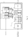
- TSN-compliant Ethernet controller 1 is shown in greater detail.
- the Ethernet controller 1 includes a receive path (not shown) and a transmit path 32 which includes a transmit handler 33, a set of N transmit queues 2 (where N ⁇ 2, e.g., 8), transmission selection and traffic shaping logic 35 which includes a set of N gates 4 and transmission media access controller (MAC) 37.
- N 2, e.g., 8
- transmission selection and traffic shaping logic 35 which includes a set of N gates 4
- transmission media access controller (MAC) 37 transmission media access controller
- the transmit handler 33 fetches frames 6 from user RAM 24 or other memory or buffer which may receive the data from a source, such as digital camera (not shown). In the case of a switch, the transmit handler 33 receives frames 6 from the routing engine (not shown).
- the transmission selection and traffic shaping logic 35 may implement credit-based shaping (CBS), strict priority round robin (SRR), round robin (RR), and/or time-aware shaping (TAS).
- CBS credit-based shaping
- SRR strict priority round robin
- RR round robin
- TAS time-aware shaping
- Individual gate control lists 7 are stored either in special function register (SFRs) 38 or in RAM (not shown) in the Ethernet controller 1.
- SFRs special function register
- a set of shadow individual gate control lists 7' and shadow configuration data may be provided to enable dynamic TAS schedule reconfiguration. Different lists 7, 7' and configuration data can be written to and accessed using respective base addresses.
- the Ethernet controller 1 also includes a set of gate controllers 39, each controller 39 arranged to read a respective individual gate control list 7 and issue a control signal 40 to a corresponding gate 4.
- the gate controllers 39 implement a set of state machines (not shown) including a cycle timer state machine (not shown), a list execute state machine (not shown) and a list configuration state machine (not shown) as specified in Clause 8.6.9 of IEEE 802.1 Qbv -2015.
- the control signal 40 may be a time, for example, in microseconds.
- the control signal 40 may be a remaining time, for example, in microseconds, before the gate changes state, or before the gate opens or closes (in the case that the state is defined).
- the control signal 40 be expressed in terms of number of bytes before the gate changes state, or before the gate opens or closes.
- Gate close time is used if the time aware shaper supports implicit guard band. This is hardware support to ensure that frames do not cross gate close time. In some cases, this can be monitored and controlled by application software.
- an individual gate control list 7 and associated configuration data 8, 9 is shown.
- the configuration data 8, 9 can include configuration data 8 which is specific to a respective individual gate control list 7 and configuration data 9 which shared amongst the individual gate control list 7.
- a shadow individual gate control list 7' has the same structure.
- a shadow configuration data (not shown) has the same structure.
- the individual gate control list 7 includes M entries 10 (where M ⁇ 1), each entry comprising a gate time 11 and control data 12.
- the control data 12 can indicate a gate state, i.e., open or closed, and/or whether the entry is the end of the list (EOL). Closed and open may be represented by logical '0' and '1' respectively. End of list may be represented by '1'.
- the individual gate control list 7 or the configuration data 8 may include a flag or field 13 indicating an initial start state i.e., open or closed.
- the configuration data 8 may include a gate list offset 14 which can be used to access entry 1 (i.e., the first entry 10 after the initial entry 10 i ), and an optional gate list length 15 (which may be omitted if the last entry is masked in control field 10 of list).
- a flag 16 for signaling re-configuration e.g. switching to an alternative list, i.e., to the shadow list 7' or vice versa for all queues and a cycle start time 17 can be specified.
- the switch to an alternative list can be triggered in hardware or by software.
- the start time 17 is an absolute time at which a cycle of gate operations for a given list 7, 7' begins.
- the cycle start time 17 is not directly defined in IEEE 802.1 Qbv -2015 ibid.
- the start time 17 is a pre-calculated number which may be calculated by software (i.e., by application software running on the CPU) and then written to hardware (i.e. to the cyrcle start time field 17 in the SFR 38).
- Clause 8.6.9.1.1 of IEEE 802.1 Qbv -2015 specifies a CycleStartTime.
- Software can calculate the CycleStartTime and provide the result to hardware.
- the software may be too slow to provide the result in time and, thus, may end up providing a cycle start time in the past. Therefore, a margin allowing for a delay in software execution may be needed to avoid or prevent this from happening.
- Hardware can observe times in the past. However, the hardware can be limited such that it only accepts a cycle start time in a given window in the future (for example to a two-second window). In this case, software handles bigger offsets using a software timer (not shown).
- the cycle start time 17 defines the start of a first cycle.
- the TAS cycle time is defined by the sum of the times in the common gate control list.
- the sum should equal OperCycleTime defined in IEEE 802.1 Qbv-2015.
- the common gate control list may be shortened or lengthen to meet this requirement. For example, an entry in the common gate control list having a long period (say, 51 ms) may be discarded and replaced by one with a shorter period (say, 50 ms).
- the sum of the times in the common gate control list is likely to be equal to OperCycleTime and so this may not be required.
- the reconfiguration flag 16 can be triggered by a timer (not shown) in hardware.
- the timer may set a time, for example, in the last slot of the common gate control list before the ConfigChangeTime (see clause 8.6.9.3.1).
- a margin allowing for a delay in calculating a configuration change time may be included, similar to that used for the cycle start time.
- Figure 13a shows an individual gate control list 7 for a toggling gate.
- An initial entry 10 i is found using the base address without applying the offset 14 ( Figure 11 ).
- the initial entry 10 i defines an initial gate state and an initial time. After the initial entry 10 i , the entries 10 come in pairs 18. The end of the list 7 is signaled in the control data 12. The cycle starts again with a second entry 10.
- Figure 13b shows an individual gate control list 7 for a gate whose state does not change.
- the initial entry 10 i is marked as the end of list. This is taken as indicating that the gate does not toggle and that its state does not change during a cycle.
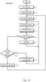
- the application software 28 reads the control data 29 (step S0.1) and transforms the control data 29 into a set of individual gate control lists 7 or a set of shadow gate individual control lists 7' (step S0.2 to S0.10). This can be performed before operations begin, i.e., before frame transmission begins. If shadow lists 7' are available, then writing of one set of gate control lists 7, 7', while the another set of gate control lists 7, 7' is being used. As explained earlier, the application software 28 inspects each gate individual control list 7 to determine if the first and last entries are in the same state (steps S0.4 & S0.5). If so, a new entry 8 is generated (step So.6), time is added from the first entry to the last entry (step S0.7) and a non-zero offset 14 is set (step So.8).
- the gate controller 39 sets an initial state (step S1.1) and waits until the start time (step S1.2).
- the gate controller 39 goes through the list of entries 10 starting from the initial entry. If there is a gate state transition, then the gate controller 39 reads out the state and gate time (step S1.4), generates a control signal and waits the specified time (step S1.5).
- the gate controller 39 goes through the list of entries 8 (step S1.4 to S1.7) reading the time (step S1.4) and generating a control signal for the gate (step S1.5) until it reaches the end of the list (step S1.6).
- the gate controller 39 checks the configuration change flag 16 (step S1.8).
- step S1.9 If the flag 16 is set, then the process of gate control ends and the controller 39 waits for a new start time (step S1.9). If the flag 16 is not set, then the controller 39 starts the cycle again either at the initial entry 10 i or at the next entry 10, depending on the offset 14 (step S1.10).
- the reconfiguration flag is requested in a way that reconfiguration becomes active at the end of a TAS cycle of the common gate control list.
- the request can be triggered either by software or by hardware based on a ⁇ reconfiguration time' or 'last cycle time'.
- the 'new cycle start' time defines when the TAS schedule re-starts with a new configuration.
- the configuration state machine (not shown) switches between active and shadow configuration. It is possible to make reuse of the SFR of the 'Cycle start time' configuration.
- Time-aware shapers can be used in a variety of time-sensitive networking, such as audio/video streaming and real-time control in automotive or industrial control applications.
- a motor vehicle 41 is shown in which a time-sensitive network 42 is deployed.
- the network 42 comprises a plurality of end stations 43 and bridges 44 interconnecting the end stations 43.
- One or more of the end stations 43 and bridges 44 may perform transmission of data 45 using a time-aware shaper as defined in IEEE 802.1 Qbv using individual control gate lists as herein described.
- each individual gate control list 7 may explicitly specify a gate state (i.e., open or closed) and a time.
Landscapes
- Engineering & Computer Science (AREA)
- Computer Networks & Wireless Communication (AREA)
- Signal Processing (AREA)
- Health & Medical Sciences (AREA)
- Computing Systems (AREA)
- General Health & Medical Sciences (AREA)
- Medical Informatics (AREA)
- Computer Security & Cryptography (AREA)
- Data Exchanges In Wide-Area Networks (AREA)
- Small-Scale Networks (AREA)
Claims (12)
- Netzwerkvorrichtung (1) für zeitempfindliche Vernetzung, umfassend:einen Satz von Warteschlangen (2); undeinen zeitbewussten Shaper (3), der Folgendes umfasst:einen Satz von Gates (4),einen Satz von Gate-Steuerungen (39), undGate-Steueranweisungen (5);wobei die Gate-Steueranweisungen Folgendes umfassen:einen Satz von einzelnen Gate-Steuerlisten (7), wobei jede einzelne Gate-Steuerliste konfiguriert ist, um ein jeweiliges Gate zu steuern, wobei jedes Gate einer Warteschlange in dem Satz von Warteschlangen entspricht;dadurch gekennzeichnet, dass jede einzelne Gate-Steuerliste Folgendes umfasst:
eine Sequenz von Einträgen (10) beginnend mit einem Anfangseintrag (10i), der auf leer gesetzt ist, und gefolgt von einem ersten Eintrag für das jeweilige Gate, wobei j eder nachfolgende Eintrag Folgendes umfasst:
ein Steuerfeld (12), das einen Gate-Zustand von entweder offen oder geschlossen für das jeweilige Gate spezifiziert, und eine kumulierte Zeitdauer, die einen oder mehrere Zeitschlitze für den Gate-Zustand umfasst, wobei zumindest ein Eintrag in der Sequenz von Einträgen eine Vielzahl von Zeitschlitzen umfasst, und wobei, wenn der erste und der letzte Gate-Zustand gleich sind, jeder Eintrag in der Sequenz von Einträgen um eine Eintragsposition bewegt wird, sodass der erste Eintrag der Anfangseintrag wird und die Dauer des letzten Eintrags durch Hinzufügen der Dauer modifiziert wird, die in dem ersten Eintrag spezifiziert wurde; und jede Gate-Steuerung aus dem Satz von Gate-Steuerungen (39) konfiguriert ist, um eine einzelne Gate-Steuerliste (7) zu lesen, um ein Gate-Steuersignal (40) zu erzeugen und um das Gate-Steuersignal an ein jeweiliges Gate (4) auszugeben, wobei jede Gate-Steuerung konfiguriert ist, um in einem ersten Zyklus jeden Eintrag in der Sequenz von Einträgen beginnend mit dem Anfangseintrag zu lesen und um den Zustand des Gates als Reaktion auf das Lesen jedes Eintrags umzuschalten und um in einem zweiten, nachfolgenden Zyklus Einträge in der Sequenz beginnend mit dem ersten Eintrag zu lesen und um den Zustand des Gates als Reaktion auf das Lesen jedes Eintrags umzuschalten. - Netzwerkvorrichtung nach Anspruch 1, wobei ein Eintrag (10) in der Sequenz von Einträgen (10) ein Steuerfeld (12) beinhaltet, das Listenende angibt.
- Netzwerkvorrichtung nach Anspruch 1 oder 2, ferner umfassend Konfigurationsdaten (9), die mit jeder einzelnen Gate-Steuerliste (7) assoziiert sind.
- Netzwerkvorrichtung nach einem der Ansprüche 1 bis 3, ferner umfassend:einen Datenhandler (33) zum Zuweisen von Daten zu dem Satz von Warteschlangen, und/odereine Medienzugriffssteuerung (37).
- Netzwerkvorrichtung nach einem der Ansprüche 1 bis 4, wobei die Netzwerkvorrichtung eine Ethernet-Steuerung ist.
- Netzwerkvorrichtung nach einem der Ansprüche 1 bis 5, die in Hardware implementiert ist.
- Monolithische integrierte Schaltung, umfassend:
die Netzwerkvorrichtung nach einem der Ansprüche 1 bis 6, optional ferner umfassend:zumindest eine zentrale Verarbeitungseinheit (23), und/oderDirektzugriffsspeicher (24), und/odereine Routing-Engine, und/odereinen physischen Schnittstellensendeempfänger. - Endstation, umfassend die Netzwerkvorrichtung nach einem der Ansprüche 1 bis 6 oder die monolithische integrierte Schaltung nach Anspruch 7.
- Schalter, umfassend die Netzwerkvorrichtung nach einem der Ansprüche 1 bis 6 oder die monolithische integrierte Schaltung nach Anspruch 7.
- Netzwerk, umfassend:ein Bussystem;zumindest eine Netzwerkvorrichtung nach einem der Ansprüche 1 bis 6, zumindest eine monolithische integrierte Schaltung nach Anspruch 7, zumindest eine Endstation nach Anspruch 8 und/oder zumindest einen Schalter nach Anspruch 9, die mit dem Bussystem verbunden sind.
- Kraftfahrzeug, umfassend zumindest eine Netzwerkvorrichtung nach einem der Ansprüche 1 bis 6, zumindest eine monolithische integrierte Schaltung nach Anspruch 7, zumindest eine Endstation nach Anspruch 8 und/oder zumindest einen Schalter nach Anspruch 9.
- Verfahren, umfassend:Empfangen von Daten, die Betrieb eines Satzes von Gates beschreiben;Umwandeln der Daten in einen Satz von einzelnen Gate-Steuerlisten (7), wobei jede einzelne Gate-Steuerliste konfiguriert ist, um ein jeweiliges Gate zu steuern und die eine Sequenz von Einträgen (10) umfasst, beginnend mit einem Anfangseintrag (10i), der auf leer gesetzt ist, und gefolgt von einem ersten Eintrag, wobei jeder nachfolgende Eintrag ein Steuerfeld (12) umfasst, das einen Gate-Zustand von entweder offen oder geschlossen für das jeweilige Gate spezifiziert, und eine kumulierte Zeitdauer, die einen oder mehrere Zeitschlitze für den Gate-Zustand umfasst, wobei zumindest ein Eintrag in der Sequenz von Einträgen eine Vielzahl von Zeitschlitzen umfasst, und wobei, wenn der erste und der letzte Gate-Zustand gleich sind, jeder Eintrag in der Sequenz von Einträgen um eine Eintragsposition nach vorne bewegt wird, sodass der erste Eintrag zu dem Anfangseintrag wird und die Dauer des letzten Eintrags durch Hinzufügen der Dauer modifiziert wird, die in dem ersten Eintrag spezifiziert wurde;Schreiben des Satzes von einzelnen Gate-Steuerlisten in Speicher oder Satz von Registern;in einem ersten Zyklus Lesen jedes Eintrags in der Sequenz von Einträgen beginnend mit dem Anfangseintrag und Umschalten des Zustand des Gates als Reaktion auf das Lesen jedes Eintrags und in einem zweiten, nachfolgenden Zyklus Lesen von Einträgen in der Sequenz beginnend mit dem ersten Eintrag und Umschalten des Zustands des Gates als Reaktion auf das Lesen jedes Eintrags;Erzeugen eines Gate-Steuersignals (40) für jeden gelesenen Eintrag; undAusgeben des Gate-Steuersignals an das Gate.
Applications Claiming Priority (1)
| Application Number | Priority Date | Filing Date | Title |
|---|---|---|---|
| PCT/EP2018/051681 WO2019145028A1 (en) | 2018-01-24 | 2018-01-24 | Time-sensitive networking |
Publications (2)
| Publication Number | Publication Date |
|---|---|
| EP3744054A1 EP3744054A1 (de) | 2020-12-02 |
| EP3744054B1 true EP3744054B1 (de) | 2024-11-20 |
Family
ID=61027741
Family Applications (1)
| Application Number | Title | Priority Date | Filing Date |
|---|---|---|---|
| EP18701470.9A Active EP3744054B1 (de) | 2018-01-24 | 2018-01-24 | Zeitempfindliche vernetzung |
Country Status (3)
| Country | Link |
|---|---|
| US (1) | US11811665B2 (de) |
| EP (1) | EP3744054B1 (de) |
| WO (1) | WO2019145028A1 (de) |
Families Citing this family (26)
| Publication number | Priority date | Publication date | Assignee | Title |
|---|---|---|---|---|
| WO2019193031A1 (de) * | 2018-04-04 | 2019-10-10 | Siemens Aktiengesellschaft | Datenübertragung in zeitsensitiven datennetzen |
| WO2020039538A1 (ja) * | 2018-08-23 | 2020-02-27 | 三菱電機株式会社 | 通信装置、通信方法及び通信プログラム |
| CN110891026B (zh) * | 2018-09-07 | 2022-11-25 | 华为技术有限公司 | 一种流量调度方法、设备及系统 |
| US11202222B2 (en) * | 2018-10-24 | 2021-12-14 | Qualcomm Incorporated | Quality of service mapping for time-sensitive network traffic in a wireless communication system |
| US12166683B2 (en) | 2018-11-19 | 2024-12-10 | Telefonaktiebolaget Lm Ericsson (Publ) | Output pacing in a cellular communications system serving as a time-sensitive networking (TSN) node |
| US10754816B2 (en) * | 2018-12-21 | 2020-08-25 | Intel Corporation | Time sensitive networking device |
| EP3912322B1 (de) | 2019-01-15 | 2024-03-06 | Telefonaktiebolaget LM Ericsson (publ) | Qos-mapping und ran-optimierung von tsn-zellularem kommunikationssystem auf basis von verkehrsmusterbezogenen informationen |
| CN113424463B (zh) * | 2019-02-14 | 2022-12-06 | 瑞典爱立信有限公司 | 对虚拟TSN桥接器管理、QoS映射和TSN Qbv调度的5G系统支持 |
| EP3977708A1 (de) | 2019-06-03 | 2022-04-06 | Telefonaktiebolaget Lm Ericsson (Publ) | Tsn- und 5gs-qos-mapping - ein auf der benutzerebene basierendes verfahren |
| WO2021031977A1 (en) * | 2019-08-16 | 2021-02-25 | Telefonaktiebolaget Lm Ericsson (Publ) | Method and application entity for virtual tsn bridge |
| CN113542157B (zh) * | 2020-04-13 | 2024-06-28 | 华为技术有限公司 | 一种时间敏感网络中门状态的控制方法及相关设备 |
| JP7337750B2 (ja) * | 2020-06-01 | 2023-09-04 | 株式会社東芝 | 通信制御装置、通信制御方法、情報処理装置、情報処理方法、および、プログラム |
| CN115735353B (zh) * | 2020-06-11 | 2025-11-25 | 瑞典爱立信有限公司 | 用于5g与多个tsc/tsn域之间的交互的方法和系统 |
| CN112235194B (zh) * | 2020-09-03 | 2022-03-25 | 北京邮电大学 | 在线路由调度时延敏感流量的方法和装置 |
| WO2022117201A1 (en) * | 2020-12-04 | 2022-06-09 | Huawei Technologies Co., Ltd. | Device and method for queues release and optimization based on run-time adaptive and dynamic gate control list strategy |
| JP7467325B2 (ja) * | 2020-12-17 | 2024-04-15 | 株式会社東芝 | 通信制御装置、通信制御方法、情報処理装置、情報処理方法、および、プログラム |
| CN113225266B (zh) * | 2021-03-17 | 2022-06-07 | 西安电子科技大学 | 一种准动态平台上tas调度方法与装置 |
| CN113068263B (zh) * | 2021-03-26 | 2022-07-05 | 鹏城实验室 | 一种时间敏感网络时隙调度方法、终端及存储介质 |
| WO2022229712A1 (en) * | 2021-04-26 | 2022-11-03 | Telefonaktiebolaget Lm Ericsson (Publ) | Gate controlled frame or packet replication and elimination function in cloud environment |
| JP7700031B2 (ja) * | 2021-12-01 | 2025-06-30 | 株式会社東芝 | 通信制御装置、情報処理装置、通信制御方法、情報処理方法及びプログラム |
| JP7717591B2 (ja) * | 2021-12-01 | 2025-08-04 | 株式会社東芝 | 通信制御装置、情報処理装置、通信制御方法、情報処理方法及びプログラム |
| CN114205315B (zh) * | 2021-12-30 | 2024-04-19 | 湖南华芯通网络科技有限公司 | 一种时间敏感网络中支持Qbv机制的帧输出调度方法 |
| EP4478811A4 (de) * | 2022-02-24 | 2025-03-26 | Shenzhen Yinwang Intelligent Technologies Co., Ltd. | Verfahren und vorrichtung zur umschaltung einer gate-steuerliste in zeitempfindlicher vernetzung |
| CN114979030B (zh) * | 2022-05-12 | 2024-07-16 | 昆高新芯微电子(江苏)有限公司 | 大规模时间敏感网络异步门控的实现方法和系统 |
| CN115622942A (zh) * | 2022-10-18 | 2023-01-17 | 中车南京浦镇车辆有限公司 | 一种采用时间划片数据调度策略的网络控制方法及系统 |
| CN115883482B (zh) * | 2023-02-27 | 2023-06-06 | 鹏城实验室 | 一种增强tsn设备门控列表的实现方法及相关设备 |
Family Cites Families (6)
| Publication number | Priority date | Publication date | Assignee | Title |
|---|---|---|---|---|
| US9219693B2 (en) * | 2012-02-22 | 2015-12-22 | Marvell World Trade Ltd. | Network devices with time aware medium access controller |
| US9960872B2 (en) * | 2012-03-08 | 2018-05-01 | Marvell International Ltd. | Systems and methods for performing a soft-block of a queue based on a size of a remaining period of a guard band |
| US9749147B2 (en) * | 2014-12-29 | 2017-08-29 | Harman International Industries, Incorporated | Ethernet AVB for time-sensitive networks |
| US10218628B2 (en) * | 2017-04-12 | 2019-02-26 | General Electric Company | Time sensitive network (TSN) scheduler with verification |
| US10425321B2 (en) * | 2017-04-25 | 2019-09-24 | Keysight Technologies Singapore (Sales) Pte. Ltd. | Methods, systems, and computer readable media for testing time sensitive network (TSN) elements |
| US10743269B2 (en) * | 2018-11-26 | 2020-08-11 | Nokia Solutions And Networks Oy | Coordinated timing syncronization and time-aware shaping |
-
2018
- 2018-01-24 EP EP18701470.9A patent/EP3744054B1/de active Active
- 2018-01-24 WO PCT/EP2018/051681 patent/WO2019145028A1/en not_active Ceased
- 2018-01-24 US US16/961,845 patent/US11811665B2/en active Active
Also Published As
| Publication number | Publication date |
|---|---|
| WO2019145028A1 (en) | 2019-08-01 |
| EP3744054A1 (de) | 2020-12-02 |
| US20200389405A1 (en) | 2020-12-10 |
| US11811665B2 (en) | 2023-11-07 |
Similar Documents
| Publication | Publication Date | Title |
|---|---|---|
| EP3744054B1 (de) | Zeitempfindliche vernetzung | |
| US11831554B2 (en) | Packet forwarding method and apparatus, system, device, and storage medium | |
| JP7394960B2 (ja) | データ送信方法及び装置 | |
| KR102206529B1 (ko) | 제네릭 인터페이스를 제공하기 위한 방법 및 제네릭 인터페이스를 구비한 마이크로컨트롤러 | |
| KR102205776B1 (ko) | 제네릭 인터페이스를 제공하기 위한 방법 및 제네릭 인터페이스를 구비한 마이크로컨트롤러 | |
| US10397332B2 (en) | In-vehicle communication system | |
| KR102202408B1 (ko) | 제네릭 인터페이스를 제공하기 위한 방법 및 제네릭 인터페이스를 구비한 마이크로컨트롤러 | |
| US10853308B1 (en) | Method and apparatus for direct memory access transfers | |
| US10965492B2 (en) | Method for transmitting data packets, controller and system having a controller | |
| US9258246B2 (en) | Integrated circuit device and methods for performing cut-through forwarding | |
| CN115396380B (zh) | 基于时间敏感网络的数据流传输方法、装置及设备 | |
| WO2021017667A1 (zh) | 业务数据的传输方法和装置 | |
| CN107040477B (zh) | 在基于以太网的运载工具中网络中的调度帧的切换 | |
| CN107040440B (zh) | 在基于以太网的运载工具中网络中启动触发的方法和设备 | |
| Meyer et al. | DoS Protection through Credit Based Metering--Simulation-Based Evaluation for Time-Sensitive Networking in Cars | |
| Do et al. | Method and analysis for the improvement of preemption performance in IEEE 802.1 TSN | |
| CN114024916B (zh) | 数据传输方法、装置、计算机可读存储介质及处理器 | |
| WO2023221486A1 (zh) | 报文处理的方法和装置 | |
| US20240039756A1 (en) | Can communication controller and method of operating can communication controller | |
| CN119174155B (zh) | 自适应流量仲裁引擎 | |
| EP4401363B1 (de) | Vorrichtung zur vermeidung von kollisionen auf physikalischer schicht und verfahren zur durchführung einer notfallübertragung dafür | |
| Asif et al. | A new approach for mixed bandwidth deterministic communication using Ethernet | |
| Yoo et al. | Unidirectional ring ethernet and media access controller with automatic relaying for low-complexity in-vehicle control network | |
| CN117376374A (zh) | 车载以太网架构及车辆 | |
| CN121367625A (zh) | 一种多优先级链式dma的网络数据监听存储方法及装置 |
Legal Events
| Date | Code | Title | Description |
|---|---|---|---|
| STAA | Information on the status of an ep patent application or granted ep patent |
Free format text: STATUS: UNKNOWN |
|
| STAA | Information on the status of an ep patent application or granted ep patent |
Free format text: STATUS: THE INTERNATIONAL PUBLICATION HAS BEEN MADE |
|
| PUAI | Public reference made under article 153(3) epc to a published international application that has entered the european phase |
Free format text: ORIGINAL CODE: 0009012 |
|
| STAA | Information on the status of an ep patent application or granted ep patent |
Free format text: STATUS: REQUEST FOR EXAMINATION WAS MADE |
|
| 17P | Request for examination filed |
Effective date: 20200723 |
|
| AK | Designated contracting states |
Kind code of ref document: A1 Designated state(s): AL AT BE BG CH CY CZ DE DK EE ES FI FR GB GR HR HU IE IS IT LI LT LU LV MC MK MT NL NO PL PT RO RS SE SI SK SM TR |
|
| AX | Request for extension of the european patent |
Extension state: BA ME |
|
| DAV | Request for validation of the european patent (deleted) | ||
| DAX | Request for extension of the european patent (deleted) | ||
| STAA | Information on the status of an ep patent application or granted ep patent |
Free format text: STATUS: EXAMINATION IS IN PROGRESS |
|
| 17Q | First examination report despatched |
Effective date: 20220314 |
|
| REG | Reference to a national code |
Ref country code: DE Ref legal event code: R079 Free format text: PREVIOUS MAIN CLASS: H04L0012815000 Ipc: H04L0047220000 Ref document number: 602018076685 Country of ref document: DE |
|
| GRAP | Despatch of communication of intention to grant a patent |
Free format text: ORIGINAL CODE: EPIDOSNIGR1 |
|
| STAA | Information on the status of an ep patent application or granted ep patent |
Free format text: STATUS: GRANT OF PATENT IS INTENDED |
|
| RIC1 | Information provided on ipc code assigned before grant |
Ipc: H04L 47/62 20220101ALI20240812BHEP Ipc: H04L 47/22 20220101AFI20240812BHEP |
|
| INTG | Intention to grant announced |
Effective date: 20240822 |
|
| GRAS | Grant fee paid |
Free format text: ORIGINAL CODE: EPIDOSNIGR3 |
|
| GRAA | (expected) grant |
Free format text: ORIGINAL CODE: 0009210 |
|
| STAA | Information on the status of an ep patent application or granted ep patent |
Free format text: STATUS: THE PATENT HAS BEEN GRANTED |
|
| AK | Designated contracting states |
Kind code of ref document: B1 Designated state(s): AL AT BE BG CH CY CZ DE DK EE ES FI FR GB GR HR HU IE IS IT LI LT LU LV MC MK MT NL NO PL PT RO RS SE SI SK SM TR |
|
| REG | Reference to a national code |
Ref country code: GB Ref legal event code: FG4D |
|
| REG | Reference to a national code |
Ref country code: CH Ref legal event code: EP |
|
| REG | Reference to a national code |
Ref country code: DE Ref legal event code: R096 Ref document number: 602018076685 Country of ref document: DE |
|
| REG | Reference to a national code |
Ref country code: IE Ref legal event code: FG4D |
|
| REG | Reference to a national code |
Ref country code: LT Ref legal event code: MG9D |
|
| REG | Reference to a national code |
Ref country code: NL Ref legal event code: MP Effective date: 20241120 |
|
| PG25 | Lapsed in a contracting state [announced via postgrant information from national office to epo] |
Ref country code: HR Free format text: LAPSE BECAUSE OF FAILURE TO SUBMIT A TRANSLATION OF THE DESCRIPTION OR TO PAY THE FEE WITHIN THE PRESCRIBED TIME-LIMIT Effective date: 20241120 Ref country code: IS Free format text: LAPSE BECAUSE OF FAILURE TO SUBMIT A TRANSLATION OF THE DESCRIPTION OR TO PAY THE FEE WITHIN THE PRESCRIBED TIME-LIMIT Effective date: 20250320 Ref country code: PT Free format text: LAPSE BECAUSE OF FAILURE TO SUBMIT A TRANSLATION OF THE DESCRIPTION OR TO PAY THE FEE WITHIN THE PRESCRIBED TIME-LIMIT Effective date: 20250320 |
|
| PGFP | Annual fee paid to national office [announced via postgrant information from national office to epo] |
Ref country code: DE Payment date: 20250129 Year of fee payment: 8 |
|
| PG25 | Lapsed in a contracting state [announced via postgrant information from national office to epo] |
Ref country code: FI Free format text: LAPSE BECAUSE OF FAILURE TO SUBMIT A TRANSLATION OF THE DESCRIPTION OR TO PAY THE FEE WITHIN THE PRESCRIBED TIME-LIMIT Effective date: 20241120 Ref country code: NL Free format text: LAPSE BECAUSE OF FAILURE TO SUBMIT A TRANSLATION OF THE DESCRIPTION OR TO PAY THE FEE WITHIN THE PRESCRIBED TIME-LIMIT Effective date: 20241120 |
|
| REG | Reference to a national code |
Ref country code: AT Ref legal event code: MK05 Ref document number: 1744584 Country of ref document: AT Kind code of ref document: T Effective date: 20241120 |
|
| PG25 | Lapsed in a contracting state [announced via postgrant information from national office to epo] |
Ref country code: BG Free format text: LAPSE BECAUSE OF FAILURE TO SUBMIT A TRANSLATION OF THE DESCRIPTION OR TO PAY THE FEE WITHIN THE PRESCRIBED TIME-LIMIT Effective date: 20241120 |
|
| PG25 | Lapsed in a contracting state [announced via postgrant information from national office to epo] |
Ref country code: ES Free format text: LAPSE BECAUSE OF FAILURE TO SUBMIT A TRANSLATION OF THE DESCRIPTION OR TO PAY THE FEE WITHIN THE PRESCRIBED TIME-LIMIT Effective date: 20241120 |
|
| PG25 | Lapsed in a contracting state [announced via postgrant information from national office to epo] |
Ref country code: NO Free format text: LAPSE BECAUSE OF FAILURE TO SUBMIT A TRANSLATION OF THE DESCRIPTION OR TO PAY THE FEE WITHIN THE PRESCRIBED TIME-LIMIT Effective date: 20250220 |
|
| PG25 | Lapsed in a contracting state [announced via postgrant information from national office to epo] |
Ref country code: LV Free format text: LAPSE BECAUSE OF FAILURE TO SUBMIT A TRANSLATION OF THE DESCRIPTION OR TO PAY THE FEE WITHIN THE PRESCRIBED TIME-LIMIT Effective date: 20241120 Ref country code: GR Free format text: LAPSE BECAUSE OF FAILURE TO SUBMIT A TRANSLATION OF THE DESCRIPTION OR TO PAY THE FEE WITHIN THE PRESCRIBED TIME-LIMIT Effective date: 20250221 Ref country code: AT Free format text: LAPSE BECAUSE OF FAILURE TO SUBMIT A TRANSLATION OF THE DESCRIPTION OR TO PAY THE FEE WITHIN THE PRESCRIBED TIME-LIMIT Effective date: 20241120 |
|
| PG25 | Lapsed in a contracting state [announced via postgrant information from national office to epo] |
Ref country code: PL Free format text: LAPSE BECAUSE OF FAILURE TO SUBMIT A TRANSLATION OF THE DESCRIPTION OR TO PAY THE FEE WITHIN THE PRESCRIBED TIME-LIMIT Effective date: 20241120 |
|
| PG25 | Lapsed in a contracting state [announced via postgrant information from national office to epo] |
Ref country code: RS Free format text: LAPSE BECAUSE OF FAILURE TO SUBMIT A TRANSLATION OF THE DESCRIPTION OR TO PAY THE FEE WITHIN THE PRESCRIBED TIME-LIMIT Effective date: 20250220 |
|
| PG25 | Lapsed in a contracting state [announced via postgrant information from national office to epo] |
Ref country code: SM Free format text: LAPSE BECAUSE OF FAILURE TO SUBMIT A TRANSLATION OF THE DESCRIPTION OR TO PAY THE FEE WITHIN THE PRESCRIBED TIME-LIMIT Effective date: 20241120 |
|
| PG25 | Lapsed in a contracting state [announced via postgrant information from national office to epo] |
Ref country code: DK Free format text: LAPSE BECAUSE OF FAILURE TO SUBMIT A TRANSLATION OF THE DESCRIPTION OR TO PAY THE FEE WITHIN THE PRESCRIBED TIME-LIMIT Effective date: 20241120 |
|
| PG25 | Lapsed in a contracting state [announced via postgrant information from national office to epo] |
Ref country code: EE Free format text: LAPSE BECAUSE OF FAILURE TO SUBMIT A TRANSLATION OF THE DESCRIPTION OR TO PAY THE FEE WITHIN THE PRESCRIBED TIME-LIMIT Effective date: 20241120 |
|
| PG25 | Lapsed in a contracting state [announced via postgrant information from national office to epo] |
Ref country code: RO Free format text: LAPSE BECAUSE OF FAILURE TO SUBMIT A TRANSLATION OF THE DESCRIPTION OR TO PAY THE FEE WITHIN THE PRESCRIBED TIME-LIMIT Effective date: 20241120 |
|
| PG25 | Lapsed in a contracting state [announced via postgrant information from national office to epo] |
Ref country code: SK Free format text: LAPSE BECAUSE OF FAILURE TO SUBMIT A TRANSLATION OF THE DESCRIPTION OR TO PAY THE FEE WITHIN THE PRESCRIBED TIME-LIMIT Effective date: 20241120 |
|
| PG25 | Lapsed in a contracting state [announced via postgrant information from national office to epo] |
Ref country code: CZ Free format text: LAPSE BECAUSE OF FAILURE TO SUBMIT A TRANSLATION OF THE DESCRIPTION OR TO PAY THE FEE WITHIN THE PRESCRIBED TIME-LIMIT Effective date: 20241120 |
|
| PG25 | Lapsed in a contracting state [announced via postgrant information from national office to epo] |
Ref country code: IT Free format text: LAPSE BECAUSE OF FAILURE TO SUBMIT A TRANSLATION OF THE DESCRIPTION OR TO PAY THE FEE WITHIN THE PRESCRIBED TIME-LIMIT Effective date: 20241120 |
|
| REG | Reference to a national code |
Ref country code: DE Ref legal event code: R097 Ref document number: 602018076685 Country of ref document: DE |
|
| REG | Reference to a national code |
Ref country code: CH Ref legal event code: PL |
|
| PG25 | Lapsed in a contracting state [announced via postgrant information from national office to epo] |
Ref country code: SE Free format text: LAPSE BECAUSE OF FAILURE TO SUBMIT A TRANSLATION OF THE DESCRIPTION OR TO PAY THE FEE WITHIN THE PRESCRIBED TIME-LIMIT Effective date: 20241120 |
|
| PG25 | Lapsed in a contracting state [announced via postgrant information from national office to epo] |
Ref country code: MC Free format text: LAPSE BECAUSE OF FAILURE TO SUBMIT A TRANSLATION OF THE DESCRIPTION OR TO PAY THE FEE WITHIN THE PRESCRIBED TIME-LIMIT Effective date: 20241120 Ref country code: LU Free format text: LAPSE BECAUSE OF NON-PAYMENT OF DUE FEES Effective date: 20250124 |
|
| PLBE | No opposition filed within time limit |
Free format text: ORIGINAL CODE: 0009261 |
|
| STAA | Information on the status of an ep patent application or granted ep patent |
Free format text: STATUS: NO OPPOSITION FILED WITHIN TIME LIMIT |
|
| PG25 | Lapsed in a contracting state [announced via postgrant information from national office to epo] |
Ref country code: BE Free format text: LAPSE BECAUSE OF NON-PAYMENT OF DUE FEES Effective date: 20250131 |
|
| PG25 | Lapsed in a contracting state [announced via postgrant information from national office to epo] |
Ref country code: FR Free format text: LAPSE BECAUSE OF NON-PAYMENT OF DUE FEES Effective date: 20250131 |
|
| PG25 | Lapsed in a contracting state [announced via postgrant information from national office to epo] |
Ref country code: CH Free format text: LAPSE BECAUSE OF NON-PAYMENT OF DUE FEES Effective date: 20250131 |
|
| 26N | No opposition filed |
Effective date: 20250821 |
|
| REG | Reference to a national code |
Ref country code: BE Ref legal event code: MM Effective date: 20250131 |
|
| GBPC | Gb: european patent ceased through non-payment of renewal fee |
Effective date: 20250220 |
|
| PG25 | Lapsed in a contracting state [announced via postgrant information from national office to epo] |
Ref country code: GB Free format text: LAPSE BECAUSE OF NON-PAYMENT OF DUE FEES Effective date: 20250220 |
|
| PG25 | Lapsed in a contracting state [announced via postgrant information from national office to epo] |
Ref country code: IE Free format text: LAPSE BECAUSE OF NON-PAYMENT OF DUE FEES Effective date: 20250124 |