EP3743571B1 - Composite building panel and shell - Google Patents
Composite building panel and shell Download PDFInfo
- Publication number
- EP3743571B1 EP3743571B1 EP19743095.2A EP19743095A EP3743571B1 EP 3743571 B1 EP3743571 B1 EP 3743571B1 EP 19743095 A EP19743095 A EP 19743095A EP 3743571 B1 EP3743571 B1 EP 3743571B1
- Authority
- EP
- European Patent Office
- Prior art keywords
- tongue
- panel
- outer shell
- groove
- shell
- Prior art date
- Legal status (The legal status is an assumption and is not a legal conclusion. Google has not performed a legal analysis and makes no representation as to the accuracy of the status listed.)
- Active
Links
- 239000002131 composite material Substances 0.000 title claims description 21
- 239000000463 material Substances 0.000 claims description 29
- 239000002184 metal Substances 0.000 claims description 5
- 238000005728 strengthening Methods 0.000 claims description 4
- 239000011257 shell material Substances 0.000 description 33
- 238000004049 embossing Methods 0.000 description 4
- 206010044565 Tremor Diseases 0.000 description 3
- 238000005452 bending Methods 0.000 description 2
- 230000005587 bubbling Effects 0.000 description 2
- 238000009924 canning Methods 0.000 description 2
- 239000011248 coating agent Substances 0.000 description 2
- 238000000576 coating method Methods 0.000 description 2
- 230000006835 compression Effects 0.000 description 2
- 238000007906 compression Methods 0.000 description 2
- 230000000007 visual effect Effects 0.000 description 2
- 206010003402 Arthropod sting Diseases 0.000 description 1
- 229910000831 Steel Inorganic materials 0.000 description 1
- 238000007792 addition Methods 0.000 description 1
- 230000004075 alteration Effects 0.000 description 1
- 230000001010 compromised effect Effects 0.000 description 1
- 238000010276 construction Methods 0.000 description 1
- 230000032798 delamination Effects 0.000 description 1
- 230000003111 delayed effect Effects 0.000 description 1
- 230000007717 exclusion Effects 0.000 description 1
- 230000009970 fire resistant effect Effects 0.000 description 1
- 239000000446 fuel Substances 0.000 description 1
- 230000003993 interaction Effects 0.000 description 1
- 238000005304 joining Methods 0.000 description 1
- 238000000034 method Methods 0.000 description 1
- 238000012986 modification Methods 0.000 description 1
- 230000004048 modification Effects 0.000 description 1
- 239000011505 plaster Substances 0.000 description 1
- 238000004080 punching Methods 0.000 description 1
- 230000035939 shock Effects 0.000 description 1
- 230000007480 spreading Effects 0.000 description 1
- 238000003892 spreading Methods 0.000 description 1
- 239000010959 steel Substances 0.000 description 1
- 210000005182 tip of the tongue Anatomy 0.000 description 1
- 230000007704 transition Effects 0.000 description 1
Images


Classifications
-
- E—FIXED CONSTRUCTIONS
- E04—BUILDING
- E04B—GENERAL BUILDING CONSTRUCTIONS; WALLS, e.g. PARTITIONS; ROOFS; FLOORS; CEILINGS; INSULATION OR OTHER PROTECTION OF BUILDINGS
- E04B1/00—Constructions in general; Structures which are not restricted either to walls, e.g. partitions, or floors or ceilings or roofs
- E04B1/62—Insulation or other protection; Elements or use of specified material therefor
- E04B1/92—Protection against other undesired influences or dangers
- E04B1/94—Protection against other undesired influences or dangers against fire
- E04B1/941—Building elements specially adapted therefor
- E04B1/942—Building elements specially adapted therefor slab-shaped
-
- E—FIXED CONSTRUCTIONS
- E04—BUILDING
- E04B—GENERAL BUILDING CONSTRUCTIONS; WALLS, e.g. PARTITIONS; ROOFS; FLOORS; CEILINGS; INSULATION OR OTHER PROTECTION OF BUILDINGS
- E04B1/00—Constructions in general; Structures which are not restricted either to walls, e.g. partitions, or floors or ceilings or roofs
- E04B1/38—Connections for building structures in general
- E04B1/61—Connections for building structures in general of slab-shaped building elements with each other
- E04B1/6108—Connections for building structures in general of slab-shaped building elements with each other the frontal surfaces of the slabs connected together
- E04B1/612—Connections for building structures in general of slab-shaped building elements with each other the frontal surfaces of the slabs connected together by means between frontal surfaces
- E04B1/6125—Connections for building structures in general of slab-shaped building elements with each other the frontal surfaces of the slabs connected together by means between frontal surfaces with protrusions on the one frontal surface co-operating with recesses in the other frontal surface
- E04B1/6133—Connections for building structures in general of slab-shaped building elements with each other the frontal surfaces of the slabs connected together by means between frontal surfaces with protrusions on the one frontal surface co-operating with recesses in the other frontal surface the connection made by friction-grip
-
- E—FIXED CONSTRUCTIONS
- E04—BUILDING
- E04C—STRUCTURAL ELEMENTS; BUILDING MATERIALS
- E04C2/00—Building elements of relatively thin form for the construction of parts of buildings, e.g. sheet materials, slabs, or panels
- E04C2/02—Building elements of relatively thin form for the construction of parts of buildings, e.g. sheet materials, slabs, or panels characterised by specified materials
- E04C2/26—Building elements of relatively thin form for the construction of parts of buildings, e.g. sheet materials, slabs, or panels characterised by specified materials composed of materials covered by two or more of groups E04C2/04, E04C2/08, E04C2/10 or of materials covered by one of these groups with a material not specified in one of the groups
- E04C2/284—Building elements of relatively thin form for the construction of parts of buildings, e.g. sheet materials, slabs, or panels characterised by specified materials composed of materials covered by two or more of groups E04C2/04, E04C2/08, E04C2/10 or of materials covered by one of these groups with a material not specified in one of the groups at least one of the materials being insulating
- E04C2/292—Building elements of relatively thin form for the construction of parts of buildings, e.g. sheet materials, slabs, or panels characterised by specified materials composed of materials covered by two or more of groups E04C2/04, E04C2/08, E04C2/10 or of materials covered by one of these groups with a material not specified in one of the groups at least one of the materials being insulating composed of insulating material and sheet metal
-
- E—FIXED CONSTRUCTIONS
- E04—BUILDING
- E04B—GENERAL BUILDING CONSTRUCTIONS; WALLS, e.g. PARTITIONS; ROOFS; FLOORS; CEILINGS; INSULATION OR OTHER PROTECTION OF BUILDINGS
- E04B1/00—Constructions in general; Structures which are not restricted either to walls, e.g. partitions, or floors or ceilings or roofs
- E04B1/02—Structures consisting primarily of load-supporting, block-shaped, or slab-shaped elements
- E04B1/04—Structures consisting primarily of load-supporting, block-shaped, or slab-shaped elements the elements consisting of concrete, e.g. reinforced concrete, or other stone-like material
- E04B1/043—Connections specially adapted therefor
-
- E—FIXED CONSTRUCTIONS
- E04—BUILDING
- E04B—GENERAL BUILDING CONSTRUCTIONS; WALLS, e.g. PARTITIONS; ROOFS; FLOORS; CEILINGS; INSULATION OR OTHER PROTECTION OF BUILDINGS
- E04B1/00—Constructions in general; Structures which are not restricted either to walls, e.g. partitions, or floors or ceilings or roofs
- E04B1/02—Structures consisting primarily of load-supporting, block-shaped, or slab-shaped elements
- E04B1/14—Structures consisting primarily of load-supporting, block-shaped, or slab-shaped elements the elements being composed of two or more materials
-
- E—FIXED CONSTRUCTIONS
- E04—BUILDING
- E04B—GENERAL BUILDING CONSTRUCTIONS; WALLS, e.g. PARTITIONS; ROOFS; FLOORS; CEILINGS; INSULATION OR OTHER PROTECTION OF BUILDINGS
- E04B1/00—Constructions in general; Structures which are not restricted either to walls, e.g. partitions, or floors or ceilings or roofs
- E04B1/38—Connections for building structures in general
- E04B1/61—Connections for building structures in general of slab-shaped building elements with each other
- E04B1/6108—Connections for building structures in general of slab-shaped building elements with each other the frontal surfaces of the slabs connected together
- E04B1/612—Connections for building structures in general of slab-shaped building elements with each other the frontal surfaces of the slabs connected together by means between frontal surfaces
- E04B1/6145—Connections for building structures in general of slab-shaped building elements with each other the frontal surfaces of the slabs connected together by means between frontal surfaces with recesses in both frontal surfaces co-operating with an additional connecting element
- E04B1/615—Connections for building structures in general of slab-shaped building elements with each other the frontal surfaces of the slabs connected together by means between frontal surfaces with recesses in both frontal surfaces co-operating with an additional connecting element the connection made by expansion
-
- E—FIXED CONSTRUCTIONS
- E04—BUILDING
- E04C—STRUCTURAL ELEMENTS; BUILDING MATERIALS
- E04C2/00—Building elements of relatively thin form for the construction of parts of buildings, e.g. sheet materials, slabs, or panels
- E04C2/02—Building elements of relatively thin form for the construction of parts of buildings, e.g. sheet materials, slabs, or panels characterised by specified materials
- E04C2/04—Building elements of relatively thin form for the construction of parts of buildings, e.g. sheet materials, slabs, or panels characterised by specified materials of concrete or other stone-like material; of asbestos cement; of cement and other mineral fibres
- E04C2/06—Building elements of relatively thin form for the construction of parts of buildings, e.g. sheet materials, slabs, or panels characterised by specified materials of concrete or other stone-like material; of asbestos cement; of cement and other mineral fibres reinforced
-
- E—FIXED CONSTRUCTIONS
- E04—BUILDING
- E04C—STRUCTURAL ELEMENTS; BUILDING MATERIALS
- E04C2/00—Building elements of relatively thin form for the construction of parts of buildings, e.g. sheet materials, slabs, or panels
- E04C2/02—Building elements of relatively thin form for the construction of parts of buildings, e.g. sheet materials, slabs, or panels characterised by specified materials
- E04C2/26—Building elements of relatively thin form for the construction of parts of buildings, e.g. sheet materials, slabs, or panels characterised by specified materials composed of materials covered by two or more of groups E04C2/04, E04C2/08, E04C2/10 or of materials covered by one of these groups with a material not specified in one of the groups
- E04C2/28—Building elements of relatively thin form for the construction of parts of buildings, e.g. sheet materials, slabs, or panels characterised by specified materials composed of materials covered by two or more of groups E04C2/04, E04C2/08, E04C2/10 or of materials covered by one of these groups with a material not specified in one of the groups combinations of materials fully covered by groups E04C2/04 and E04C2/08
-
- E—FIXED CONSTRUCTIONS
- E04—BUILDING
- E04C—STRUCTURAL ELEMENTS; BUILDING MATERIALS
- E04C2/00—Building elements of relatively thin form for the construction of parts of buildings, e.g. sheet materials, slabs, or panels
- E04C2/30—Building elements of relatively thin form for the construction of parts of buildings, e.g. sheet materials, slabs, or panels characterised by the shape or structure
- E04C2/38—Building elements of relatively thin form for the construction of parts of buildings, e.g. sheet materials, slabs, or panels characterised by the shape or structure with attached ribs, flanges, or the like, e.g. framed panels
-
- E—FIXED CONSTRUCTIONS
- E04—BUILDING
- E04C—STRUCTURAL ELEMENTS; BUILDING MATERIALS
- E04C2/00—Building elements of relatively thin form for the construction of parts of buildings, e.g. sheet materials, slabs, or panels
- E04C2/44—Building elements of relatively thin form for the construction of parts of buildings, e.g. sheet materials, slabs, or panels characterised by the purpose
- E04C2/52—Building elements of relatively thin form for the construction of parts of buildings, e.g. sheet materials, slabs, or panels characterised by the purpose with special adaptations for auxiliary purposes, e.g. serving for locating conduits
- E04C2/526—Building elements of relatively thin form for the construction of parts of buildings, e.g. sheet materials, slabs, or panels characterised by the purpose with special adaptations for auxiliary purposes, e.g. serving for locating conduits with adaptations not otherwise provided for, for connecting, transport; for making impervious or hermetic, e.g. sealings
-
- E—FIXED CONSTRUCTIONS
- E04—BUILDING
- E04B—GENERAL BUILDING CONSTRUCTIONS; WALLS, e.g. PARTITIONS; ROOFS; FLOORS; CEILINGS; INSULATION OR OTHER PROTECTION OF BUILDINGS
- E04B2/00—Walls, e.g. partitions, for buildings; Wall construction with regard to insulation; Connections specially adapted to walls
- E04B2/02—Walls, e.g. partitions, for buildings; Wall construction with regard to insulation; Connections specially adapted to walls built-up from layers of building elements
- E04B2002/0202—Details of connections
- E04B2002/0204—Non-undercut connections, e.g. tongue and groove connections
-
- E—FIXED CONSTRUCTIONS
- E04—BUILDING
- E04C—STRUCTURAL ELEMENTS; BUILDING MATERIALS
- E04C2/00—Building elements of relatively thin form for the construction of parts of buildings, e.g. sheet materials, slabs, or panels
- E04C2/02—Building elements of relatively thin form for the construction of parts of buildings, e.g. sheet materials, slabs, or panels characterised by specified materials
- E04C2/26—Building elements of relatively thin form for the construction of parts of buildings, e.g. sheet materials, slabs, or panels characterised by specified materials composed of materials covered by two or more of groups E04C2/04, E04C2/08, E04C2/10 or of materials covered by one of these groups with a material not specified in one of the groups
-
- E—FIXED CONSTRUCTIONS
- E04—BUILDING
- E04C—STRUCTURAL ELEMENTS; BUILDING MATERIALS
- E04C2/00—Building elements of relatively thin form for the construction of parts of buildings, e.g. sheet materials, slabs, or panels
- E04C2/30—Building elements of relatively thin form for the construction of parts of buildings, e.g. sheet materials, slabs, or panels characterised by the shape or structure
- E04C2/34—Building elements of relatively thin form for the construction of parts of buildings, e.g. sheet materials, slabs, or panels characterised by the shape or structure composed of two or more spaced sheet-like parts
-
- E—FIXED CONSTRUCTIONS
- E04—BUILDING
- E04C—STRUCTURAL ELEMENTS; BUILDING MATERIALS
- E04C2/00—Building elements of relatively thin form for the construction of parts of buildings, e.g. sheet materials, slabs, or panels
- E04C2002/001—Mechanical features of panels
- E04C2002/004—Panels with profiled edges, e.g. stepped, serrated
-
- E—FIXED CONSTRUCTIONS
- E04—BUILDING
- E04F—FINISHING WORK ON BUILDINGS, e.g. STAIRS, FLOORS
- E04F13/00—Coverings or linings, e.g. for walls or ceilings
- E04F13/07—Coverings or linings, e.g. for walls or ceilings composed of covering or lining elements; Sub-structures therefor; Fastening means therefor
- E04F13/08—Coverings or linings, e.g. for walls or ceilings composed of covering or lining elements; Sub-structures therefor; Fastening means therefor composed of a plurality of similar covering or lining elements
- E04F13/0889—Coverings or linings, e.g. for walls or ceilings composed of covering or lining elements; Sub-structures therefor; Fastening means therefor composed of a plurality of similar covering or lining elements characterised by the joints between neighbouring elements, e.g. with joint fillings or with tongue and groove connections
- E04F13/0894—Coverings or linings, e.g. for walls or ceilings composed of covering or lining elements; Sub-structures therefor; Fastening means therefor composed of a plurality of similar covering or lining elements characterised by the joints between neighbouring elements, e.g. with joint fillings or with tongue and groove connections with tongue and groove connections
-
- E—FIXED CONSTRUCTIONS
- E04—BUILDING
- E04F—FINISHING WORK ON BUILDINGS, e.g. STAIRS, FLOORS
- E04F2201/00—Joining sheets or plates or panels
- E04F2201/02—Non-undercut connections, e.g. tongue and groove connections
- E04F2201/023—Non-undercut connections, e.g. tongue and groove connections with a continuous tongue or groove
Definitions
- the present invention relates to composite building panels, particularly to composite building panels of the type that have an outer shell and a concrete infill material.
- the present invention also relates to shells for composite building panels.
- Composite building panels of the type that typically have a sheet metal outer shell that is then infilled with a concrete material are well known.
- these panels are rectangular in side profile and include along side edges corresponding tongue and grove features to allow for interlocking of like panels to form a wall.
- Such panels are very effective at resisting fire and have a very long time to complete failure once compromised as they maintain their structural integrity. Even if significant cracks occur in a wall made of such panels (which typically occur at the join) and flames can pass through, the remainder of the wall will remain in place so that only a small amount of flames are able to pass through, thereby restricting the spread of fire. Accordingly, a fire can burn within the building without catastrophic failure and even during a large scale fire, the wall contributes to the structural integrity of the building even when damaged. This is in contrast to plaster panels having a fire resistant coating, which tend to reach catastrophic failure very quickly once the coating has been damaged and the core of the material is exposed to the fire and heat.
- Previous composite panels such as those described in Australian patent no. 707873 for example, have a tongue having a square or generally rectangular profile, which provides some resistance to buckling, though due to the shallow tongue creates gaps in the wall that can reduce fire ratings.
- panels having a square tongue the stress of the wall is carried at the base of the tongue, thereby limiting its strength.
- Another panel system with male/female connecting structures is disclosed in US8677713 .
- the interface between the inner wall of the outer shell and the concrete infill material may slip, relative to one another. This can impose excessive compressive and/or strain load on the concrete material, causing the concrete material to lose its structural integrity and for the entire panel to fail, sometimes catastrophically.
- the outer shell may buckle and/or rupture, and this may also cause the concrete infill material to catastrophically fail.
- Other typical modes of failure attributed to geological events are caused by the likely aftershocks that occur.
- substantially the entire exterior and interior surface of the shell, excluding the tongue and groove, includes an embossed pattern.
- the embossed pattern can be a repeating pattern.
- the repeat pattern is preferably a geometric shape.
- the embossed pattern on the interior surface of the shell provides increased grip between an infill material and the inner surface of the shell.
- the shell can be fabricated from sheet metal.
- the shell preferably is fabricated from two sheets, the sheets overlapping each other at the tongue portion and the groove portion to provide additional strength at the tongue portion and groove portion.
- an end of each sheet extends 5 to 10mm along a side of the parallel portion or a corresponding portion of the groove portion. More preferably, the sheets overlap on the parallel portion and the groove portion so as to provide for engagement of four layers of sheet material at corners of the groove portion/tongue portion.
- a composite building panel having an outer shell of the above described type and a concrete infill material.
- the infill material fills the entire volume of the shell.
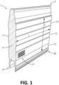
- Figure 1 illustrates a composite building panel 1 according to a preferred embodiment of the invention.
- the panel 1 includes an outer shell 3 which is completely filled with a suitable concrete infill material 5.
- the panel is rectangular shaped, and includes a tongue portion 7 extending outwardly from one side edge of the panel 1 and a correspondingly configured groove portion 9 extending outwardly from an opposite side edge, whereby the tongue 7 of one panel can be received in the groove 9 of a like panel for interlocking like panels together to form a wall.
- the tongue 7 and groove 9 are sized so that the tongue 7 is a tight fit into groove 9.
- the tongue 7 extends outwardly from the side edge of the panel 1 and has a forward portion 15 ( Figure 6 ) with parallel sides 17 which are substantially straight and substantially parallel to a central plane of the panel 1, thereby creating a square or rectangular profile.
- the tongue 7 extends along a central plane of the panel 1, i.e. the parallel sides 17 are equidistant from the central plane, though it will be appreciated that in other embodiments, the tongue 7 may be offset to one side of the central plane.
- the parallel sides 17 may be 12 to 30mm long.
- the tongue 7 has an intermediate portion 19 with side walls 20 that taper outwardly from the parallel sides 17 toward respective side faces 21 of the panel 1. It will be appreciated that the intermediate potion 19 may not extend all the way to the side faces 21. In the illustrated embodiment, walls 20 transition into an "S" shape before reaching the side faces 21. In this regard, a rearward portion 22 also with parallel sides 24 is disposed between the intermediate portion 20 and the side faces 13. Importantly, inner faces 23 ( Figure 2 ) of the groove 9 are configured for close engagement of the forward, intermediate and rear portions 15, 19, 22 of the tongue 7.
- This straight/wedge/straight wall configuration on the tongue can result in superior fitment of like panels.
- the initial straight section, forward portion 15, allows for an improved structural interlock between the panels.
- the wedge, intermediate portion 19, allows for two like panels to fit snugly together, providing a good air seal.
- Rearward portion 22 also provides an improved structural interlock, as well as a flat face that allows screws to be used to secure two like panels together. The combination of these features provides a greatly improved connection over the prior art.
- the intermediate portion 19 is between 20 and 45mm long, with side walls 20 having a taper angle in the order of 3 to 30 degrees.
- Rear portion 24 is also preferably between 12 and 30mm long.
- the described forward portion 15 allows for positive engagement of the tongue 7 with the corresponding section of inner face 23 of groove 9 to prevent buckling of the wall.
- Figure 6 illustrates how this can be achieved.
- panel 1A tends to rotate counter clockwise and panel 1b tends to rotate clockwise as shown as arrows R1 and R2.
- This causes increased surface pressure at locations X1 and X2, as well as along the tapered portion, forcing the top corner edge of the tongue 7 at the parallel portion into the corresponding corner of the groove 9, which acts to counter rotation of the panels and prevent buckling and/or bending of the wall.
- the tapered walls of the intermediate portion 19 of the tongue 7 act to transfer a percentage of the force along the joint.
- a face of the tapered portion 20 bears against a corresponding face of the groove 9, resulting in forces each in a direction normal to their respective surfaces.
- This force is at an angle to a central plane of the panel 1 and includes vector components acting in vertical and horizontal directions, thereby creating a "sideways" force that forces the end of the tongue 7 into the groove 9 at location X1 and resists pulling apart of the panels.
- a frictional resistance to pulling out is also created.
- panel 1 takes the benefits of panels having a generally square tongue/groove and combines them with a tapered tongue/groove (whereas previous panels had either configuration) to result in a panel providing a longer engagement area and having greatly improved buckling, pulling out resistance and fire resistance.
- Panel 1 provides a deep square joint so that in the event of fire, even as gaps open between panels, the tongue and groove features do not provide a clear path for a fire to propagate, thereby reducing fire spread within a building. Previous catastrophic fires have occurred when panels "open up” and allow a direct propagation path for a fire, resulting a rapid spreading of fire throughout the building. If this event can be delayed or substantially avoided, the fire resistance of a building can be increased.
- the shell 3 is formed from a sheet material, which is preferably sheet metal, and which is preferably 0.2 to 0.7mm thick.
- the shell 3 is formed from multiple parts that come together with a male/female interlocking fit. The location of the edges of each sheet is selected to create a stiffer panel at the point where loading is high, particularly near the tongue portion 7 and groove portion 9.
- the shell 3 is formed of two sheets 3a, 3b, with each sheet overlapping the other at the tongue portion 7 and the groove portion 9.
- the panels may be secured together at location Y, a position through which a central plane extends, using a joint such as a stitch, which may be provided along the tongue 7.
- each sheet extends a distance W1 from a tip of the tongue portion 7 along the side of each of the parallel wall portions 17 so that both corners of the tongue portion have a twin walled shell.
- distance W1 is 5 to 10 mm. This provides that at the point of stress concentration X1 additional material is provided to resist deformation under buckling load, thereby strengthening the tongue portion 7 and the joint and further preventing buckling of the wall.
- the corners of the tongue portion are offset from a central plane of the panel 10, providing additional clearance here provided increased strength to the panel.
- sheets 3a, 3b also overlap so as to provide additional strength to the groove portion 9 at point of stress concentration X1.
- the sheets overlap a distance W2 along side walls of the groove, that distance preferably being 5 to 10mm.
- the overlap of the sheets 3a, 3b in the groove portion 9 also act to resist deformation under buckling load, thereby strengthening the groove portion 9 and the joint and further preventing buckling of the wall.
- the overlapping sheets 3a, 3b in the tongue portion 7 and the groove portion 9 react against a corresponding surface of each other to resist shear movement.
- the panel 1 can resist compression.
- the infill material resists compression so that the sheets 3a, 3b cannot buckle and are forced to move over each other.
- the shell 3 is folded over itself to provide additional material to resist deformation.
- three layers of steel are provided to resist deformation.
- the overlapping areas are only small in size, owing to the additional material thickness they make a great contribution to the strength of the panel thereby resisting stretching when tensile loads are applied.
- the two sheets 3a, 3b are joined or stitched using common joining techniques such as punching, coining or riveting.
- common joining techniques such as punching, coining or riveting.
- the composite building panel 1 includes a plurality of longitudinal grooves 13, though it will be appreciated that such grooves may be omitted.
- panels of typical width i.e. in the range of 200mm to 400mm, will have three grooves 13.
- Grooves 13 are provided to stiffen panel 1 and resist bending.
- ripples or folds 25 may also be formed in the shell 3.
- Ripples 25 are provided near the groove portion 9 to further enhance the strength of the panel, particularly to prevent opening of the groove portion 9.
- the ripples 25 are preferably between 0.3mm and 0.5mm thick. Further ripples may also be disposed between ribs 13 and also near the tongue 7.
- Ripples 25 are provided near the groove 9 near an edge of the material, this point being one where stretching of the panel 1 is at a maximum. Previous panels have tended to buckle at this location, which may now be avoided.
- the sides of the panel 1 between the tongue portion 7 and the groove portion 9 can include an embossed repeating pattern (not shown) to improve the failure resistance of the composite building panel resulting from loads imposed upon the panel by excessive vibration, for example during major geological events, such as earthquakes.
- embossing has been used for decorative purposes and the improve the visual appearance by reducing bubbling oil canning.
- embossing is used to improve the strength of the panel.
- the repeating pattern can be any geometric shape, particular circular or rectilinear, however any suitable pattern could be used, and still fit within the scope of the present invention.
- the geometric shapes are preferably spaced so that between them further strengthening cross ribs 11 are formed extending straight across the panel in horizontal and vertical directions, as partially illustrated in Figure 1 .
- the embossed repeating pattern may extend partially or substantially across the entirety of the sides of the panel, in which case the patterns would extend from the tongue portion 7 to the groove portion 19 and across ribs 13, i.e. the area shown in Figure 1 by lines L.
- the cross ribs 11 can extend diagonally across the face of the panel.
- the cross ribs are between 0.3 and 0.8mm deep.
- an embossed repeating pattern is included on both the exterior surface of the outer shell 3 and on the interior surface of the outer shell 3.
- the embossed repeating pattern that is included on the interior surface increases the grip between the concrete infill material 5 and the outer shell 3. This significantly reduces the likelihood of slippage between the outer shell 3 and the concrete infill material 5, when the composite building panel 1 is under severe vibratory load, like that experienced in an earth tremor or earthquake.
- the presence of the embossed repeating pattern on the exterior surface of the outer shell enables the outer shell 3 to withstand the successive severe compressive and strain loads generated by earth tremors and earthquakes without buckling, bulging or tearing.
- the embossed pattern allows the thickness of the shell material to be thinner than it would otherwise need to be. This reduces material cost, and the weight of the composite building panel. The thinner material also reduces the energy required to perform the embossing.
- the combination of the enhanced grip between the in-fill material and the inner wall of the shell, and the enhanced strength, also provided by the embossing, enables the composite building panel to mitigate the risk of catastrophic failure due to the initial shock loads caused by geological event, such as an earthquake, and also subsequent repeat aftershock events.
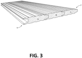
- a plurality of like panels 1 may be interconnected as shown in Figure 3 to form a wall.
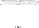
- a first wall 1A may be advanced toward a second wall 1B, or vice versa, as shown in Figure 4 .
- Either the first or second walls may be secured within a building (using any suitable conventional means) prior to the other wall being brought into engagement with it. Once engaged, the other wall may also be secured within the building ready for panel 1C to be installed in the wall. It will be appreciated that many panels may be interconnected to form a long wall.
- the above described panel includes numerous unique features that act together to more evenly distribute loads, such as buckling loads in particular, over the panel and move stress away from a single point.
- loads such as buckling loads in particular
- the result of this interaction of the features is that the panel provides greater strength resistance to buckling and pull out loads, and greater fire resistance.
Landscapes
- Engineering & Computer Science (AREA)
- Architecture (AREA)
- Civil Engineering (AREA)
- Structural Engineering (AREA)
- Physics & Mathematics (AREA)
- Electromagnetism (AREA)
- Building Environments (AREA)
- Finishing Walls (AREA)
- Laminated Bodies (AREA)
Description
- The present invention relates to composite building panels, particularly to composite building panels of the type that have an outer shell and a concrete infill material. The present invention also relates to shells for composite building panels.
- Composite building panels of the type that typically have a sheet metal outer shell that is then infilled with a concrete material are well known. Typically, these panels are rectangular in side profile and include along side edges corresponding tongue and grove features to allow for interlocking of like panels to form a wall.
- Such panels are very effective at resisting fire and have a very long time to complete failure once compromised as they maintain their structural integrity. Even if significant cracks occur in a wall made of such panels (which typically occur at the join) and flames can pass through, the remainder of the wall will remain in place so that only a small amount of flames are able to pass through, thereby restricting the spread of fire. Accordingly, a fire can burn within the building without catastrophic failure and even during a large scale fire, the wall contributes to the structural integrity of the building even when damaged. This is in contrast to plaster panels having a fire resistant coating, which tend to reach catastrophic failure very quickly once the coating has been damaged and the core of the material is exposed to the fire and heat.
- It has been observed that in most building fires there is a limited availability of fuel so that if the walls can remain in place without failure, the fire will eventually burn out without catastrophic building failure. This is particularly true in apartment complexes where previous fires have led to wall failure and then spread quickly through the building, leading to large human and financial cost.
- Furthermore, due to their strength composite panels having a sheet metal outer shell and concrete infill are better able to resist seismic loading without catastrophic failure compared to other commonly used internal wall systems. Even if a small amount of damage occurs during the seismic event the fire rating of the wall remains high, which is important as fires often follow seismic events.
- Previous composite panels, such as those described in
Australian patent no. 707873 US8677713 . - Also, other previous panels have had a tongue with a general wedge shape that, when engaged with a corresponding groove under force, acts to open up the groove under buckling loads or when a force is applied to one side, thereby limiting the strength of the wall. The result is that the weakest point of a wall made with such panels is the interface or join between two adjacent panels.
- It is also known to add grooves or ridges within the structure of the panel for decorative purposes and to improve the visual appearance by preventing bubbling and/or oil canning. It has been discovered that composite building panels of this kind can suffer from a failure problem when subjected to a sudden and sever vibratory load. This type of load can occur when a building that has been constructed from these types of composite building panels is subjected to an earth tremor or earthquake.
- While subjected to a severe vibratory load, the interface between the inner wall of the outer shell and the concrete infill material may slip, relative to one another. This can impose excessive compressive and/or strain load on the concrete material, causing the concrete material to lose its structural integrity and for the entire panel to fail, sometimes catastrophically.
- In another mode of failure, as the composite building panel is subjected to the tensile and compressive loads imposed upon it by a geological event, the outer shell may buckle and/or rupture, and this may also cause the concrete infill material to catastrophically fail. Other typical modes of failure attributed to geological events are caused by the likely aftershocks that occur.
- There is a need to address the above, and/or at least provide a useful alternative.
- According to the invention there is provided an outer shell with the features of claim 1.
- According to preferred embodiments of the invention, substantially the entire exterior and interior surface of the shell, excluding the tongue and groove, includes an embossed pattern. The embossed pattern can be a repeating pattern. The repeat pattern is preferably a geometric shape.
- Preferably, the embossed pattern on the interior surface of the shell provides increased grip between an infill material and the inner surface of the shell.
- The shell can be fabricated from sheet metal. The shell preferably is fabricated from two sheets, the sheets overlapping each other at the tongue portion and the groove portion to provide additional strength at the tongue portion and groove portion. In preferred embodiments, an end of each sheet extends 5 to 10mm along a side of the parallel portion or a corresponding portion of the groove portion. More preferably, the sheets overlap on the parallel portion and the groove portion so as to provide for engagement of four layers of sheet material at corners of the groove portion/tongue portion.
- According to the invention there is also provided a composite building panel having an outer shell of the above described type and a concrete infill material.
- In preferred embodiments, the infill material fills the entire volume of the shell.
- In order that the invention may be more easily understood, an embodiment will now be described, by way of example only, with reference to the accompanying drawings, in which:
- Figure 1:
- is a perspective view of a composite building panel according to a preferred embodiment of the invention;
- Figure 2:
- is a plan view of the panel of
Figure 1 ; - Figure 3:
- is a perspective view of three like panels interconnected;
- Figure 4:
- is a plan view of two like panels being brought into engagement;
- Figure 5:
- is a plan view of the two panels in an engaged condition; and
- Figure 6:
- is a close view of the panels of
Figure 5 ; - Figure 7:
- is a close view of a tongue portion of a shell for use in the panel;
- Figure 8:
- is a close view of a groove portion of the shell; and
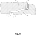
- Figure 9:
- is a very close exploded view of a tongue portion and groove portion.
-
Figure 1 illustrates a composite building panel 1 according to a preferred embodiment of the invention. - The panel 1 includes an
outer shell 3 which is completely filled with a suitableconcrete infill material 5. In this embodiment the panel is rectangular shaped, and includes atongue portion 7 extending outwardly from one side edge of the panel 1 and a correspondingly configuredgroove portion 9 extending outwardly from an opposite side edge, whereby thetongue 7 of one panel can be received in thegroove 9 of a like panel for interlocking like panels together to form a wall. Preferably, thetongue 7 andgroove 9 are sized so that thetongue 7 is a tight fit intogroove 9. - The
tongue 7 extends outwardly from the side edge of the panel 1 and has a forward portion 15 (Figure 6 ) withparallel sides 17 which are substantially straight and substantially parallel to a central plane of the panel 1, thereby creating a square or rectangular profile. In the illustrated embodiment, thetongue 7 extends along a central plane of the panel 1, i.e. theparallel sides 17 are equidistant from the central plane, though it will be appreciated that in other embodiments, thetongue 7 may be offset to one side of the central plane. Theparallel sides 17 may be 12 to 30mm long. - The
tongue 7 has an intermediate portion 19 withside walls 20 that taper outwardly from theparallel sides 17 toward respective side faces 21 of the panel 1. It will be appreciated that the intermediate potion 19 may not extend all the way to the side faces 21. In the illustrated embodiment,walls 20 transition into an "S" shape before reaching the side faces 21. In this regard, arearward portion 22 also withparallel sides 24 is disposed between theintermediate portion 20 and the side faces 13. Importantly, inner faces 23 (Figure 2 ) of thegroove 9 are configured for close engagement of the forward, intermediate andrear portions tongue 7. - This straight/wedge/straight wall configuration on the tongue can result in superior fitment of like panels. In this regard, the initial straight section,
forward portion 15, allows for an improved structural interlock between the panels. The wedge, intermediate portion 19, allows for two like panels to fit snugly together, providing a good air seal.Rearward portion 22 also provides an improved structural interlock, as well as a flat face that allows screws to be used to secure two like panels together. The combination of these features provides a greatly improved connection over the prior art. - Preferably, the intermediate portion 19 is between 20 and 45mm long, with
side walls 20 having a taper angle in the order of 3 to 30 degrees.Rear portion 24 is also preferably between 12 and 30mm long. - With previous panels with a tapered tongue and corresponding groove, when interlocked and a force is applied to one side or a buckling load otherwise induced, the groove of one panel tends to open up, which can allow the tongue to escape and the wall to fail, thereby limiting the strength of the wall. This is particularly an issue with a tongue/groove connection that is not very deep.
- With the present panel 1, the described
forward portion 15 allows for positive engagement of thetongue 7 with the corresponding section ofinner face 23 ofgroove 9 to prevent buckling of the wall.Figure 6 illustrates how this can be achieved. In particular, under sideload L panel 1A tends to rotate counter clockwise and panel 1b tends to rotate clockwise as shown as arrows R1 and R2. This causes increased surface pressure at locations X1 and X2, as well as along the tapered portion, forcing the top corner edge of thetongue 7 at the parallel portion into the corresponding corner of thegroove 9, which acts to counter rotation of the panels and prevent buckling and/or bending of the wall. - As the
tongue 7 is deeply received intogroove 9, it is possible to provide greater resistance to torque resulting from load L than previously possible. - Furthermore, the tapered walls of the intermediate portion 19 of the
tongue 7 act to transfer a percentage of the force along the joint. In this regard, under load L a face of the taperedportion 20 bears against a corresponding face of thegroove 9, resulting in forces each in a direction normal to their respective surfaces. This force is at an angle to a central plane of the panel 1 and includes vector components acting in vertical and horizontal directions, thereby creating a "sideways" force that forces the end of thetongue 7 into thegroove 9 at location X1 and resists pulling apart of the panels. Also, owing to the engagement between the faces a frictional resistance to pulling out is also created. - By providing a panel with a greater resistance to buckling loads, a wall of increased strength and greater fire resistance can be obtained.
- Advantageously, panel 1 takes the benefits of panels having a generally square tongue/groove and combines them with a tapered tongue/groove (whereas previous panels had either configuration) to result in a panel providing a longer engagement area and having greatly improved buckling, pulling out resistance and fire resistance.
- Panel 1 provides a deep square joint so that in the event of fire, even as gaps open between panels, the tongue and groove features do not provide a clear path for a fire to propagate, thereby reducing fire spread within a building. Previous catastrophic fires have occurred when panels "open up" and allow a direct propagation path for a fire, resulting a rapid spreading of fire throughout the building. If this event can be delayed or substantially avoided, the fire resistance of a building can be increased.
- The
shell 3 is formed from a sheet material, which is preferably sheet metal, and which is preferably 0.2 to 0.7mm thick. Theshell 3 is formed from multiple parts that come together with a male/female interlocking fit. The location of the edges of each sheet is selected to create a stiffer panel at the point where loading is high, particularly near thetongue portion 7 andgroove portion 9. - As illustrated in
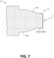
Figures 7 and8 , theshell 3 is formed of twosheets tongue portion 7 and thegroove portion 9. The panels may be secured together at location Y, a position through which a central plane extends, using a joint such as a stitch, which may be provided along thetongue 7. - At the
tongue portion 7, as illustrated inFigure 7 , an end of each sheet extends a distance W1 from a tip of thetongue portion 7 along the side of each of theparallel wall portions 17 so that both corners of the tongue portion have a twin walled shell. Preferably, distance W1 is 5 to 10 mm. This provides that at the point of stress concentration X1 additional material is provided to resist deformation under buckling load, thereby strengthening thetongue portion 7 and the joint and further preventing buckling of the wall. As the corners of the tongue portion are offset from a central plane of thepanel 10, providing additional clearance here provided increased strength to the panel. - At the
groove portion 9, as shown infigure 8 ,sheets groove portion 9 at point of stress concentration X1. Again, the sheets overlap a distance W2 along side walls of the groove, that distance preferably being 5 to 10mm. The overlap of thesheets groove portion 9 also act to resist deformation under buckling load, thereby strengthening thegroove portion 9 and the joint and further preventing buckling of the wall. - The overlapping
sheets tongue portion 7 and thegroove portion 9 react against a corresponding surface of each other to resist shear movement. In this regard, as the panel 1 is filled with concrete it can resist compression. As thetongue portion 7 andgroove portion 9 are pressed together, the infill material resists compression so that thesheets - As can be seen in
Figures 8 and9 , by overlapping the shell at thetongue portion 7 and thegroove portion 9, the result will be 4 layers of material in engagement with each other at critical loading points when the panels are interconnected. InFigure 8 , these layers are urged against each other as the two panels are pushed together. Although the overlapping areas are only small in size, owing to the additional material thickness they make a great contribution to the strength of the panel, thereby resisting stretching when tensile loads are applied. - Also, with the described sheet overlapping, on the
tongue 7 there is achieved three points of force transfer, one at the central stitch and one at either side of the panel along the overlapping edge of the sheet. - Furthermore, at location X3, the
shell 3 is folded over itself to provide additional material to resist deformation. In conjunction with the single wall of theshell 3 on therearward portion 22, against which the shell bears, three layers of steel are provided to resist deformation. Although the overlapping areas are only small in size, owing to the additional material thickness they make a great contribution to the strength of the panel thereby resisting stretching when tensile loads are applied. - Along a side edge of the panel 1 the two
sheets sheets sheets - As illustrated in
Figure 2 , the composite building panel 1 includes a plurality oflongitudinal grooves 13, though it will be appreciated that such grooves may be omitted. Preferably, panels of typical width, i.e. in the range of 200mm to 400mm, will have threegrooves 13.Grooves 13 are provided to stiffen panel 1 and resist bending. - To further stiffen the panel, ripples or folds 25 may also be formed in the
shell 3.Ripples 25 are provided near thegroove portion 9 to further enhance the strength of the panel, particularly to prevent opening of thegroove portion 9. Theripples 25 are preferably between 0.3mm and 0.5mm thick. Further ripples may also be disposed betweenribs 13 and also near thetongue 7.Ripples 25 are provided near thegroove 9 near an edge of the material, this point being one where stretching of the panel 1 is at a maximum. Previous panels have tended to buckle at this location, which may now be avoided. - In some embodiments, the sides of the panel 1 between the
tongue portion 7 and thegroove portion 9 can include an embossed repeating pattern (not shown) to improve the failure resistance of the composite building panel resulting from loads imposed upon the panel by excessive vibration, for example during major geological events, such as earthquakes. - Previously, embossing has been used for decorative purposes and the improve the visual appearance by reducing bubbling oil canning. With the present invention, embossing is used to improve the strength of the panel.
- The repeating pattern can be any geometric shape, particular circular or rectilinear, however any suitable pattern could be used, and still fit within the scope of the present invention. The geometric shapes are preferably spaced so that between them further strengthening
cross ribs 11 are formed extending straight across the panel in horizontal and vertical directions, as partially illustrated inFigure 1 . It will be appreciated that the embossed repeating pattern may extend partially or substantially across the entirety of the sides of the panel, in which case the patterns would extend from thetongue portion 7 to the groove portion 19 and acrossribs 13, i.e. the area shown inFigure 1 by lines L. In other embodiments, thecross ribs 11 can extend diagonally across the face of the panel. Preferably the cross ribs are between 0.3 and 0.8mm deep. In the form of the invention illustrated inFigure 1 , an embossed repeating pattern is included on both the exterior surface of theouter shell 3 and on the interior surface of theouter shell 3. - The embossed repeating pattern that is included on the interior surface increases the grip between the
concrete infill material 5 and theouter shell 3. This significantly reduces the likelihood of slippage between theouter shell 3 and theconcrete infill material 5, when the composite building panel 1 is under severe vibratory load, like that experienced in an earth tremor or earthquake. - The presence of the embossed repeating pattern on the exterior surface of the outer shell enables the
outer shell 3 to withstand the successive severe compressive and strain loads generated by earth tremors and earthquakes without buckling, bulging or tearing. - The embossed pattern allows the thickness of the shell material to be thinner than it would otherwise need to be. This reduces material cost, and the weight of the composite building panel. The thinner material also reduces the energy required to perform the embossing.
- The combination of the enhanced grip between the in-fill material and the inner wall of the shell, and the enhanced strength, also provided by the embossing, enables the composite building panel to mitigate the risk of catastrophic failure due to the initial shock loads caused by geological event, such as an earthquake, and also subsequent repeat aftershock events.
- A plurality of like panels 1 may be interconnected as shown in
Figure 3 to form a wall. In this regard, afirst wall 1A may be advanced toward asecond wall 1B, or vice versa, as shown inFigure 4 . Either the first or second walls may be secured within a building (using any suitable conventional means) prior to the other wall being brought into engagement with it. Once engaged, the other wall may also be secured within the building ready for panel 1C to be installed in the wall. It will be appreciated that many panels may be interconnected to form a long wall. - The above described panel includes numerous unique features that act together to more evenly distribute loads, such as buckling loads in particular, over the panel and move stress away from a single point. The result of this interaction of the features is that the panel provides greater strength resistance to buckling and pull out loads, and greater fire resistance.
- While the above description includes the preferred embodiments of the invention, it is to be understood that many variations, alterations, modifications and/or additions may be introduced into the constructions and arrangements of parts previously described without departing from the scope of the invention defined in the appended claims.
- Throughout this specification and the claims which follow, unless the context requires otherwise, the word "comprise", and variations such as "comprises" and "comprising", will be understood to imply the inclusion of a stated integer or step or group of integers or steps but not the exclusion of any other integer or step or group of integers or steps.
- The reference in this specification to any prior publication (or information derived from it), or to any matter which is known, is not, and should not be taken as an acknowledgment or admission or any form of suggestion that that prior publication (or information derived from it) or known matter forms part of the common general knowledge in the field of endeavour to which this specification relates.
Claims (12)
- An outer shell (3) for a composite building panel, the shell having a tongue (7) and correspondingly shaped groove (9) formed on opposite side edges thereof for interlocking like panels to form a wall, wherein the tongue extends outwardly from one of the said side edges of the panel and has a forward portion (15) with parallel sides which are substantially straight and substantially parallel to a central plane of the panel, an intermediate portion (19) including tapering walls which taper outwardly from the parallel sides away from the central plane towards side faces of the panel, and a rearward portion (22) also with parallel sides extending from the intermediate portion to the side faces of the panel, wherein inner faces of the groove (9) have parallel sides and a tapered intermediate portion that are configured for engagement with the tongue (7) of a like panel by abutting against_corresponding forward and rearward portions and a tapered intermediate portion (19) of the tongue of the like panel.
- An outer shell according to claim 1, wherein substantially all of an exterior and interior surface of the shell, excluding the tongue and groove, includes an embossed pattern.
- An outer shell according to claim 2, wherein the embossed pattern is a repeating pattern.
- An outer shell according to claim 3, wherein the repeating pattern is a geometric shape.
- An outer shell according to claim 2, wherein the embossed pattern on the interior surface of the shell provides increased grip between an infill material and the inner surface of the shell.
- An outer shell according to claim 1, further comprising longitudinal folds (25) formed on the side face adjacent the groove and or the tongue for strengthening the shell around the groove.
- An outer shell according to claim 1, wherein the shell is fabricated from sheet metal.
- An outer shell according to claim 1, wherein the shell is fabricated from two sheets, the sheets overlapping each other at the tongue portion and the groove portion to provide additional strength at the tongue portion and groove portion.
- An outer shell according to claim 8, wherein the overlapping on the tongue portion and the groove portion are configured to lie adjacent each other in use to provide four layers of material at a corner interface.
- An outer shell according to claim 9, wherein an end of each sheet extends 5 to 10mm along a side of a respective parallel portion or a corresponding portion of the groove portion.
- A composite building panel having an outer shell according to any preceding claim and a concrete infill material.
- A composite building panel according to claim 11, wherein the infill material fills the entire volume of the shell.
Applications Claiming Priority (2)
| Application Number | Priority Date | Filing Date | Title |
|---|---|---|---|
| AU2018900228A AU2018900228A0 (en) | 2018-01-24 | Composite Building Panel and Shell | |
| PCT/AU2019/050042 WO2019144182A1 (en) | 2018-01-24 | 2019-01-23 | Composite building panel and shell |
Publications (4)
| Publication Number | Publication Date |
|---|---|
| EP3743571A1 EP3743571A1 (en) | 2020-12-02 |
| EP3743571A4 EP3743571A4 (en) | 2021-10-27 |
| EP3743571C0 EP3743571C0 (en) | 2023-07-26 |
| EP3743571B1 true EP3743571B1 (en) | 2023-07-26 |
Family
ID=67299165
Family Applications (1)
| Application Number | Title | Priority Date | Filing Date |
|---|---|---|---|
| EP19743095.2A Active EP3743571B1 (en) | 2018-01-24 | 2019-01-23 | Composite building panel and shell |
Country Status (9)
| Country | Link |
|---|---|
| US (1) | US10590646B2 (en) |
| EP (1) | EP3743571B1 (en) |
| CN (1) | CN111630232B (en) |
| AU (1) | AU2019210700A1 (en) |
| CA (1) | CA3087457A1 (en) |
| ES (1) | ES2960450T3 (en) |
| IL (1) | IL276264B (en) |
| PL (1) | PL3743571T3 (en) |
| WO (1) | WO2019144182A1 (en) |
Families Citing this family (5)
| Publication number | Priority date | Publication date | Assignee | Title |
|---|---|---|---|---|
| USD898952S1 (en) * | 2018-08-23 | 2020-10-13 | Doug Spear | Tongue and groove for wall panel |
| US11479015B2 (en) * | 2020-02-14 | 2022-10-25 | Divergent Technologies, Inc. | Custom formed panels for transport structures and methods for assembling same |
| WO2021245443A1 (en) * | 2020-06-03 | 2021-12-09 | Arcelormittal | Building envelope |
| USD1000643S1 (en) * | 2020-07-23 | 2023-10-03 | Korok Building Systems NZ Limited | Wall panel |
| US11441309B1 (en) * | 2021-03-26 | 2022-09-13 | Signature Wall Solutions, Inc. | Wall system |
Family Cites Families (34)
| Publication number | Priority date | Publication date | Assignee | Title |
|---|---|---|---|---|
| US2975874A (en) * | 1958-04-01 | 1961-03-21 | Pagan Alberto | Girder made up of structural members |
| US3742672A (en) * | 1971-12-30 | 1973-07-03 | United Mcgill Corp | Modular building panel having interlocking edge structure |
| AT341738B (en) * | 1974-12-24 | 1978-02-27 | Hoesch Werke Ag | CONNECTING ELEMENT WITH SLOT AND SPRING CONNECTION |
| IT1038127B (en) * | 1975-05-14 | 1979-11-20 | Sips | THERMAL INSULATION PANEL PROVIDED WITH SHAPED COVERINGS CONNECTED BY APPROPRIATE INTERLOCKING ELEMENTS AND PRESENTING THE INGLOBATING EDGES OF THE SEALING GASKETS |
| DE2551905A1 (en) * | 1975-11-19 | 1977-08-25 | Hunter Douglas Ind Bv | PREFABRICATED WALL ELEMENT |
| US4186539A (en) * | 1978-02-09 | 1980-02-05 | United Mcgill Corporation | Interlocking modular building panel with sealing strip |
| US4589240A (en) * | 1984-09-19 | 1986-05-20 | Raynor Manufacturing Company | Foam core panel with interlocking skins and thermal break |
| FI91181C (en) * | 1992-07-01 | 1994-05-25 | Rautaruukki Oy | Reinforced concrete composite structure |
| US5293728A (en) * | 1992-09-17 | 1994-03-15 | Texas Aluminum Industries, Inc. | Insulated panel |
| US5274979A (en) * | 1992-12-22 | 1994-01-04 | Tsai Jui Hsing | Insulating plate unit |
| US7131242B2 (en) * | 1995-03-07 | 2006-11-07 | Pergo (Europe) Ab | Flooring panel or wall panel and use thereof |
| CA2170681A1 (en) * | 1996-02-29 | 1997-08-30 | Vittorio De Zen | Insulated wall and components therefor |
| AUPO013296A0 (en) * | 1996-05-29 | 1996-06-27 | Boral Australian Gypsum Limited | A building panel |
| AUPO389996A0 (en) | 1996-11-28 | 1996-12-19 | Verzantyoort, Timothy Wilhelmus | Building element |
| SE513151C2 (en) | 1998-02-04 | 2000-07-17 | Perstorp Flooring Ab | Guide heel at the joint including groove and spring |
| US6122879A (en) * | 1999-04-07 | 2000-09-26 | Worldwide Refrigeration Industries, Inc. | Snap together insulated panels |
| US6247281B1 (en) * | 1999-09-02 | 2001-06-19 | Gary Lin | Wall plank structure |
| US6223493B1 (en) | 1999-12-01 | 2001-05-01 | John Robert Ruggeri | Self-aligning building blocks |
| MD2287C2 (en) * | 2000-03-07 | 2004-06-30 | Е.Ф.П. ФЛОР ПРОДАКТС Фюсбёден Гм0 | Panel, in particular floor panel |
| US6415576B1 (en) * | 2000-09-25 | 2002-07-09 | Gustav M. Stromback | Reinforcing ridge apparatus and method |
| DE10101202B4 (en) * | 2001-01-11 | 2007-11-15 | Witex Ag | parquet board |
| US20040211144A1 (en) * | 2001-06-27 | 2004-10-28 | Stanchfield Oliver O. | Flooring panel or wall panel and use thereof |
| EP1361320A1 (en) * | 2002-05-10 | 2003-11-12 | Tarkett Sommer S.A. | Floorboard |
| US6739106B2 (en) * | 2002-09-12 | 2004-05-25 | Royal Group Technologies Limited | Reversible plastic building board with different colored sides |
| US7377082B1 (en) * | 2004-11-17 | 2008-05-27 | Edwards Richard D | Insulative panel incorporating a support beam |
| US7540123B1 (en) * | 2006-03-09 | 2009-06-02 | Thomas Middleton Semmes | Base for rooftop air conditioning units |
| IE86252B1 (en) * | 2007-12-14 | 2013-08-14 | Kingspan Res And Dev Ltd | A panel |
| CA2648822C (en) * | 2008-10-20 | 2014-12-09 | Arthur George Paetkau | Prefabricated building panels and structures, building, methods and systems relating to same |
| US8286399B2 (en) * | 2010-01-20 | 2012-10-16 | Hill Phoenix, Inc. | Structural insulated panel system |
| CA2766628C (en) * | 2012-01-30 | 2017-03-07 | Yvan Bergeron | Load bearing wall system |
| US8677713B1 (en) * | 2013-03-06 | 2014-03-25 | Epi 04, Inc. | Extruded wall panel system and method of forming |
| CN203742008U (en) * | 2013-10-31 | 2014-07-30 | 北京北鹏新型建材有限公司 | Composite heat preservation board used for building |
| CN104234354A (en) * | 2014-09-17 | 2014-12-24 | 广州市科帮机械设备有限公司 | Strong-strength machine-made handmade sandwich board |
| WO2018085881A1 (en) | 2016-11-10 | 2018-05-17 | Speedpanel Holdings Pty Ltd | Improved composite building panel |
-
2018
- 2018-09-17 US US16/132,959 patent/US10590646B2/en active Active
-
2019
- 2019-01-23 WO PCT/AU2019/050042 patent/WO2019144182A1/en unknown
- 2019-01-23 CA CA3087457A patent/CA3087457A1/en active Pending
- 2019-01-23 IL IL276264A patent/IL276264B/en unknown
- 2019-01-23 AU AU2019210700A patent/AU2019210700A1/en active Pending
- 2019-01-23 CN CN201980009892.2A patent/CN111630232B/en active Active
- 2019-01-23 EP EP19743095.2A patent/EP3743571B1/en active Active
- 2019-01-23 ES ES19743095T patent/ES2960450T3/en active Active
- 2019-01-23 PL PL19743095.2T patent/PL3743571T3/en unknown
Also Published As
| Publication number | Publication date |
|---|---|
| IL276264A (en) | 2020-09-30 |
| EP3743571A1 (en) | 2020-12-02 |
| WO2019144182A1 (en) | 2019-08-01 |
| CA3087457A1 (en) | 2019-08-01 |
| EP3743571C0 (en) | 2023-07-26 |
| EP3743571A4 (en) | 2021-10-27 |
| CN111630232A (en) | 2020-09-04 |
| IL276264B (en) | 2022-09-01 |
| US20190226204A1 (en) | 2019-07-25 |
| AU2019210700A1 (en) | 2020-08-13 |
| US10590646B2 (en) | 2020-03-17 |
| ES2960450T3 (en) | 2024-03-04 |
| PL3743571T3 (en) | 2024-01-15 |
| CN111630232B (en) | 2022-01-28 |
Similar Documents
| Publication | Publication Date | Title |
|---|---|---|
| EP3743571B1 (en) | Composite building panel and shell | |
| US10316519B2 (en) | Structural panel systems with a nested sidelap and method of securing | |
| JP6202465B2 (en) | Joint structure of wood members | |
| US20090193735A1 (en) | Shear lock modular building panel assembly | |
| CA2578627A1 (en) | Interlocking joint for a wall or door of a trailer | |
| US20140123587A1 (en) | Framework connecting device of prefabricated building structure | |
| AU2013384149A1 (en) | Teardrop and offset notch bridging connector | |
| JP4335006B2 (en) | Structure including structure sandwich plate member and connecting member, and method for manufacturing parts of the structure | |
| US8677708B2 (en) | Wall, roof and building structures | |
| JP6536323B2 (en) | Longitudinal structure of steel sheet pile and steel sheet pile wall | |
| KR20190113149A (en) | Precast concrete segment panel, precast concrete load-bearing walls and reinforcing method of using precast concrete load-bearing walls | |
| KR100672087B1 (en) | Closed Section Type Stud Member and Wall Pannel System using The Same | |
| JP6784307B2 (en) | Bearing wall | |
| JP2005325637A (en) | Bearing wall frame | |
| KR102141798B1 (en) | Shape steel load-bearing walls and reinforcing method of using shape steel load-bearing walls | |
| JP7380642B2 (en) | Yamagata composite construction material | |
| JP7424343B2 (en) | Composite construction material | |
| KR20190070747A (en) | Earthquake-resistance block and wall assembly | |
| AU749290B2 (en) | Fastening system for structural framing elements | |
| JP5737058B2 (en) | H-shaped sheet pile | |
| EP2253856A1 (en) | Nail Plate | |
| KR100510776B1 (en) | Arcade type lagging panel used at a sheathing work and the method installing the same | |
| KR102045623B1 (en) | Connecting structure of structural member | |
| JP2006291459A (en) | Composite-structure shaft member of steel and concrete | |
| JP6841497B2 (en) | Connecting structure of the building frame |
Legal Events
| Date | Code | Title | Description |
|---|---|---|---|
| STAA | Information on the status of an ep patent application or granted ep patent |
Free format text: STATUS: THE INTERNATIONAL PUBLICATION HAS BEEN MADE |
|
| PUAI | Public reference made under article 153(3) epc to a published international application that has entered the european phase |
Free format text: ORIGINAL CODE: 0009012 |
|
| STAA | Information on the status of an ep patent application or granted ep patent |
Free format text: STATUS: REQUEST FOR EXAMINATION WAS MADE |
|
| 17P | Request for examination filed |
Effective date: 20200804 |
|
| AK | Designated contracting states |
Kind code of ref document: A1 Designated state(s): AL AT BE BG CH CY CZ DE DK EE ES FI FR GB GR HR HU IE IS IT LI LT LU LV MC MK MT NL NO PL PT RO RS SE SI SK SM TR |
|
| AX | Request for extension of the european patent |
Extension state: BA ME |
|
| DAV | Request for validation of the european patent (deleted) | ||
| DAX | Request for extension of the european patent (deleted) | ||
| A4 | Supplementary search report drawn up and despatched |
Effective date: 20210928 |
|
| RIC1 | Information provided on ipc code assigned before grant |
Ipc: E04F 13/08 20060101ALI20210922BHEP Ipc: E04C 2/38 20060101ALI20210922BHEP Ipc: E04C 2/34 20060101ALI20210922BHEP Ipc: E04C 2/28 20060101ALI20210922BHEP Ipc: E04B 2/18 20060101ALI20210922BHEP Ipc: E04B 2/72 20060101AFI20210922BHEP |
|
| GRAP | Despatch of communication of intention to grant a patent |
Free format text: ORIGINAL CODE: EPIDOSNIGR1 |
|
| STAA | Information on the status of an ep patent application or granted ep patent |
Free format text: STATUS: GRANT OF PATENT IS INTENDED |
|
| INTG | Intention to grant announced |
Effective date: 20230224 |
|
| GRAS | Grant fee paid |
Free format text: ORIGINAL CODE: EPIDOSNIGR3 |
|
| GRAA | (expected) grant |
Free format text: ORIGINAL CODE: 0009210 |
|
| STAA | Information on the status of an ep patent application or granted ep patent |
Free format text: STATUS: THE PATENT HAS BEEN GRANTED |
|
| AK | Designated contracting states |
Kind code of ref document: B1 Designated state(s): AL AT BE BG CH CY CZ DE DK EE ES FI FR GB GR HR HU IE IS IT LI LT LU LV MC MK MT NL NO PL PT RO RS SE SI SK SM TR |
|
| REG | Reference to a national code |
Ref country code: CH Ref legal event code: EP |
|
| REG | Reference to a national code |
Ref country code: IE Ref legal event code: FG4D |
|
| REG | Reference to a national code |
Ref country code: DE Ref legal event code: R096 Ref document number: 602019033565 Country of ref document: DE |
|
| U01 | Request for unitary effect filed |
Effective date: 20230821 |
|
| U07 | Unitary effect registered |
Designated state(s): AT BE BG DE DK EE FI FR IT LT LU LV MT NL PT SE SI Effective date: 20230825 |
|
| REG | Reference to a national code |
Ref country code: LT Ref legal event code: MG9D |
|
| PG25 | Lapsed in a contracting state [announced via postgrant information from national office to epo] |
Ref country code: GR Free format text: LAPSE BECAUSE OF FAILURE TO SUBMIT A TRANSLATION OF THE DESCRIPTION OR TO PAY THE FEE WITHIN THE PRESCRIBED TIME-LIMIT Effective date: 20231027 |
|
| PG25 | Lapsed in a contracting state [announced via postgrant information from national office to epo] |
Ref country code: IS Free format text: LAPSE BECAUSE OF FAILURE TO SUBMIT A TRANSLATION OF THE DESCRIPTION OR TO PAY THE FEE WITHIN THE PRESCRIBED TIME-LIMIT Effective date: 20231126 |
|
| PG25 | Lapsed in a contracting state [announced via postgrant information from national office to epo] |
Ref country code: RS Free format text: LAPSE BECAUSE OF FAILURE TO SUBMIT A TRANSLATION OF THE DESCRIPTION OR TO PAY THE FEE WITHIN THE PRESCRIBED TIME-LIMIT Effective date: 20230726 Ref country code: NO Free format text: LAPSE BECAUSE OF FAILURE TO SUBMIT A TRANSLATION OF THE DESCRIPTION OR TO PAY THE FEE WITHIN THE PRESCRIBED TIME-LIMIT Effective date: 20231026 Ref country code: IS Free format text: LAPSE BECAUSE OF FAILURE TO SUBMIT A TRANSLATION OF THE DESCRIPTION OR TO PAY THE FEE WITHIN THE PRESCRIBED TIME-LIMIT Effective date: 20231126 Ref country code: HR Free format text: LAPSE BECAUSE OF FAILURE TO SUBMIT A TRANSLATION OF THE DESCRIPTION OR TO PAY THE FEE WITHIN THE PRESCRIBED TIME-LIMIT Effective date: 20230726 Ref country code: GR Free format text: LAPSE BECAUSE OF FAILURE TO SUBMIT A TRANSLATION OF THE DESCRIPTION OR TO PAY THE FEE WITHIN THE PRESCRIBED TIME-LIMIT Effective date: 20231027 |
|
| U20 | Renewal fee paid [unitary effect] |
Year of fee payment: 6 Effective date: 20240124 |
|
| REG | Reference to a national code |
Ref country code: ES Ref legal event code: FG2A Ref document number: 2960450 Country of ref document: ES Kind code of ref document: T3 Effective date: 20240304 |
|
| PGFP | Annual fee paid to national office [announced via postgrant information from national office to epo] |
Ref country code: ES Payment date: 20240228 Year of fee payment: 6 Ref country code: IE Payment date: 20240119 Year of fee payment: 6 |
|
| PG25 | Lapsed in a contracting state [announced via postgrant information from national office to epo] |
Ref country code: SM Free format text: LAPSE BECAUSE OF FAILURE TO SUBMIT A TRANSLATION OF THE DESCRIPTION OR TO PAY THE FEE WITHIN THE PRESCRIBED TIME-LIMIT Effective date: 20230726 Ref country code: RO Free format text: LAPSE BECAUSE OF FAILURE TO SUBMIT A TRANSLATION OF THE DESCRIPTION OR TO PAY THE FEE WITHIN THE PRESCRIBED TIME-LIMIT Effective date: 20230726 Ref country code: CZ Free format text: LAPSE BECAUSE OF FAILURE TO SUBMIT A TRANSLATION OF THE DESCRIPTION OR TO PAY THE FEE WITHIN THE PRESCRIBED TIME-LIMIT Effective date: 20230726 Ref country code: SK Free format text: LAPSE BECAUSE OF FAILURE TO SUBMIT A TRANSLATION OF THE DESCRIPTION OR TO PAY THE FEE WITHIN THE PRESCRIBED TIME-LIMIT Effective date: 20230726 |
|
| PGFP | Annual fee paid to national office [announced via postgrant information from national office to epo] |
Ref country code: GB Payment date: 20240123 Year of fee payment: 6 |