EP3743262B1 - Additively manufactured structure and method for making the same - Google Patents
Additively manufactured structure and method for making the same Download PDFInfo
- Publication number
- EP3743262B1 EP3743262B1 EP19704165.0A EP19704165A EP3743262B1 EP 3743262 B1 EP3743262 B1 EP 3743262B1 EP 19704165 A EP19704165 A EP 19704165A EP 3743262 B1 EP3743262 B1 EP 3743262B1
- Authority
- EP
- European Patent Office
- Prior art keywords
- layer structure
- forming
- support structure
- layer
- support
- Prior art date
- Legal status (The legal status is an assumption and is not a legal conclusion. Google has not performed a legal analysis and makes no representation as to the accuracy of the status listed.)
- Active
Links
Images









Classifications
-
- B—PERFORMING OPERATIONS; TRANSPORTING
- B29—WORKING OF PLASTICS; WORKING OF SUBSTANCES IN A PLASTIC STATE IN GENERAL
- B29C—SHAPING OR JOINING OF PLASTICS; SHAPING OF MATERIAL IN A PLASTIC STATE, NOT OTHERWISE PROVIDED FOR; AFTER-TREATMENT OF THE SHAPED PRODUCTS, e.g. REPAIRING
- B29C64/00—Additive manufacturing, i.e. manufacturing of three-dimensional [3D] objects by additive deposition, additive agglomeration or additive layering, e.g. by 3D printing, stereolithography or selective laser sintering
- B29C64/10—Processes of additive manufacturing
- B29C64/106—Processes of additive manufacturing using only liquids or viscous materials, e.g. depositing a continuous bead of viscous material
- B29C64/118—Processes of additive manufacturing using only liquids or viscous materials, e.g. depositing a continuous bead of viscous material using filamentary material being melted, e.g. fused deposition modelling [FDM]
-
- B—PERFORMING OPERATIONS; TRANSPORTING
- B29—WORKING OF PLASTICS; WORKING OF SUBSTANCES IN A PLASTIC STATE IN GENERAL
- B29C—SHAPING OR JOINING OF PLASTICS; SHAPING OF MATERIAL IN A PLASTIC STATE, NOT OTHERWISE PROVIDED FOR; AFTER-TREATMENT OF THE SHAPED PRODUCTS, e.g. REPAIRING
- B29C64/00—Additive manufacturing, i.e. manufacturing of three-dimensional [3D] objects by additive deposition, additive agglomeration or additive layering, e.g. by 3D printing, stereolithography or selective laser sintering
- B29C64/10—Processes of additive manufacturing
- B29C64/106—Processes of additive manufacturing using only liquids or viscous materials, e.g. depositing a continuous bead of viscous material
- B29C64/112—Processes of additive manufacturing using only liquids or viscous materials, e.g. depositing a continuous bead of viscous material using individual droplets, e.g. from jetting heads
-
- B—PERFORMING OPERATIONS; TRANSPORTING
- B29—WORKING OF PLASTICS; WORKING OF SUBSTANCES IN A PLASTIC STATE IN GENERAL
- B29C—SHAPING OR JOINING OF PLASTICS; SHAPING OF MATERIAL IN A PLASTIC STATE, NOT OTHERWISE PROVIDED FOR; AFTER-TREATMENT OF THE SHAPED PRODUCTS, e.g. REPAIRING
- B29C64/00—Additive manufacturing, i.e. manufacturing of three-dimensional [3D] objects by additive deposition, additive agglomeration or additive layering, e.g. by 3D printing, stereolithography or selective laser sintering
- B29C64/10—Processes of additive manufacturing
- B29C64/188—Processes of additive manufacturing involving additional operations performed on the added layers, e.g. smoothing, grinding or thickness control
- B29C64/194—Processes of additive manufacturing involving additional operations performed on the added layers, e.g. smoothing, grinding or thickness control during lay-up
-
- B—PERFORMING OPERATIONS; TRANSPORTING
- B29—WORKING OF PLASTICS; WORKING OF SUBSTANCES IN A PLASTIC STATE IN GENERAL
- B29C—SHAPING OR JOINING OF PLASTICS; SHAPING OF MATERIAL IN A PLASTIC STATE, NOT OTHERWISE PROVIDED FOR; AFTER-TREATMENT OF THE SHAPED PRODUCTS, e.g. REPAIRING
- B29C64/00—Additive manufacturing, i.e. manufacturing of three-dimensional [3D] objects by additive deposition, additive agglomeration or additive layering, e.g. by 3D printing, stereolithography or selective laser sintering
- B29C64/20—Apparatus for additive manufacturing; Details thereof or accessories therefor
- B29C64/205—Means for applying layers
- B29C64/209—Heads; Nozzles
-
- B—PERFORMING OPERATIONS; TRANSPORTING
- B29—WORKING OF PLASTICS; WORKING OF SUBSTANCES IN A PLASTIC STATE IN GENERAL
- B29C—SHAPING OR JOINING OF PLASTICS; SHAPING OF MATERIAL IN A PLASTIC STATE, NOT OTHERWISE PROVIDED FOR; AFTER-TREATMENT OF THE SHAPED PRODUCTS, e.g. REPAIRING
- B29C64/00—Additive manufacturing, i.e. manufacturing of three-dimensional [3D] objects by additive deposition, additive agglomeration or additive layering, e.g. by 3D printing, stereolithography or selective laser sintering
- B29C64/20—Apparatus for additive manufacturing; Details thereof or accessories therefor
- B29C64/245—Platforms or substrates
-
- B—PERFORMING OPERATIONS; TRANSPORTING
- B29—WORKING OF PLASTICS; WORKING OF SUBSTANCES IN A PLASTIC STATE IN GENERAL
- B29C—SHAPING OR JOINING OF PLASTICS; SHAPING OF MATERIAL IN A PLASTIC STATE, NOT OTHERWISE PROVIDED FOR; AFTER-TREATMENT OF THE SHAPED PRODUCTS, e.g. REPAIRING
- B29C64/00—Additive manufacturing, i.e. manufacturing of three-dimensional [3D] objects by additive deposition, additive agglomeration or additive layering, e.g. by 3D printing, stereolithography or selective laser sintering
- B29C64/30—Auxiliary operations or equipment
- B29C64/364—Conditioning of environment
-
- B—PERFORMING OPERATIONS; TRANSPORTING
- B29—WORKING OF PLASTICS; WORKING OF SUBSTANCES IN A PLASTIC STATE IN GENERAL
- B29C—SHAPING OR JOINING OF PLASTICS; SHAPING OF MATERIAL IN A PLASTIC STATE, NOT OTHERWISE PROVIDED FOR; AFTER-TREATMENT OF THE SHAPED PRODUCTS, e.g. REPAIRING
- B29C64/00—Additive manufacturing, i.e. manufacturing of three-dimensional [3D] objects by additive deposition, additive agglomeration or additive layering, e.g. by 3D printing, stereolithography or selective laser sintering
- B29C64/30—Auxiliary operations or equipment
- B29C64/386—Data acquisition or data processing for additive manufacturing
- B29C64/393—Data acquisition or data processing for additive manufacturing for controlling or regulating additive manufacturing processes
-
- B—PERFORMING OPERATIONS; TRANSPORTING
- B29—WORKING OF PLASTICS; WORKING OF SUBSTANCES IN A PLASTIC STATE IN GENERAL
- B29C—SHAPING OR JOINING OF PLASTICS; SHAPING OF MATERIAL IN A PLASTIC STATE, NOT OTHERWISE PROVIDED FOR; AFTER-TREATMENT OF THE SHAPED PRODUCTS, e.g. REPAIRING
- B29C64/00—Additive manufacturing, i.e. manufacturing of three-dimensional [3D] objects by additive deposition, additive agglomeration or additive layering, e.g. by 3D printing, stereolithography or selective laser sintering
- B29C64/40—Structures for supporting 3D objects during manufacture and intended to be sacrificed after completion thereof
-
- B—PERFORMING OPERATIONS; TRANSPORTING
- B33—ADDITIVE MANUFACTURING TECHNOLOGY
- B33Y—ADDITIVE MANUFACTURING, i.e. MANUFACTURING OF THREE-DIMENSIONAL [3D] OBJECTS BY ADDITIVE DEPOSITION, ADDITIVE AGGLOMERATION OR ADDITIVE LAYERING, e.g. BY 3D PRINTING, STEREOLITHOGRAPHY OR SELECTIVE LASER SINTERING
- B33Y10/00—Processes of additive manufacturing
-
- B—PERFORMING OPERATIONS; TRANSPORTING
- B33—ADDITIVE MANUFACTURING TECHNOLOGY
- B33Y—ADDITIVE MANUFACTURING, i.e. MANUFACTURING OF THREE-DIMENSIONAL [3D] OBJECTS BY ADDITIVE DEPOSITION, ADDITIVE AGGLOMERATION OR ADDITIVE LAYERING, e.g. BY 3D PRINTING, STEREOLITHOGRAPHY OR SELECTIVE LASER SINTERING
- B33Y30/00—Apparatus for additive manufacturing; Details thereof or accessories therefor
-
- B—PERFORMING OPERATIONS; TRANSPORTING
- B33—ADDITIVE MANUFACTURING TECHNOLOGY
- B33Y—ADDITIVE MANUFACTURING, i.e. MANUFACTURING OF THREE-DIMENSIONAL [3D] OBJECTS BY ADDITIVE DEPOSITION, ADDITIVE AGGLOMERATION OR ADDITIVE LAYERING, e.g. BY 3D PRINTING, STEREOLITHOGRAPHY OR SELECTIVE LASER SINTERING
- B33Y50/00—Data acquisition or data processing for additive manufacturing
- B33Y50/02—Data acquisition or data processing for additive manufacturing for controlling or regulating additive manufacturing processes
-
- B—PERFORMING OPERATIONS; TRANSPORTING
- B33—ADDITIVE MANUFACTURING TECHNOLOGY
- B33Y—ADDITIVE MANUFACTURING, i.e. MANUFACTURING OF THREE-DIMENSIONAL [3D] OBJECTS BY ADDITIVE DEPOSITION, ADDITIVE AGGLOMERATION OR ADDITIVE LAYERING, e.g. BY 3D PRINTING, STEREOLITHOGRAPHY OR SELECTIVE LASER SINTERING
- B33Y80/00—Products made by additive manufacturing
-
- B—PERFORMING OPERATIONS; TRANSPORTING
- B62—LAND VEHICLES FOR TRAVELLING OTHERWISE THAN ON RAILS
- B62D—MOTOR VEHICLES; TRAILERS
- B62D29/00—Superstructures, understructures, or sub-units thereof, characterised by the material thereof
- B62D29/04—Superstructures, understructures, or sub-units thereof, characterised by the material thereof predominantly of synthetic material
- B62D29/041—Understructures
-
- B—PERFORMING OPERATIONS; TRANSPORTING
- B29—WORKING OF PLASTICS; WORKING OF SUBSTANCES IN A PLASTIC STATE IN GENERAL
- B29L—INDEXING SCHEME ASSOCIATED WITH SUBCLASS B29C, RELATING TO PARTICULAR ARTICLES
- B29L2031/00—Other particular articles
- B29L2031/30—Vehicles, e.g. ships or aircraft, or body parts thereof
- B29L2031/3005—Body finishings
-
- B—PERFORMING OPERATIONS; TRANSPORTING
- B29—WORKING OF PLASTICS; WORKING OF SUBSTANCES IN A PLASTIC STATE IN GENERAL
- B29L—INDEXING SCHEME ASSOCIATED WITH SUBCLASS B29C, RELATING TO PARTICULAR ARTICLES
- B29L2031/00—Other particular articles
- B29L2031/30—Vehicles, e.g. ships or aircraft, or body parts thereof
- B29L2031/3044—Bumpers
-
- Y—GENERAL TAGGING OF NEW TECHNOLOGICAL DEVELOPMENTS; GENERAL TAGGING OF CROSS-SECTIONAL TECHNOLOGIES SPANNING OVER SEVERAL SECTIONS OF THE IPC; TECHNICAL SUBJECTS COVERED BY FORMER USPC CROSS-REFERENCE ART COLLECTIONS [XRACs] AND DIGESTS
- Y02—TECHNOLOGIES OR APPLICATIONS FOR MITIGATION OR ADAPTATION AGAINST CLIMATE CHANGE
- Y02P—CLIMATE CHANGE MITIGATION TECHNOLOGIES IN THE PRODUCTION OR PROCESSING OF GOODS
- Y02P10/00—Technologies related to metal processing
- Y02P10/25—Process efficiency
Definitions
- the first support structure is not in contact with the at least one first layer structure during the forming the second layer structure.
- the distance d can be spacing between any points on the first layer structure 210 and the support structure 240. As illustratively shown in Fig. 3 , the distance d can be size of a gap 242 between the interfacing sides 246, 216. Stated somewhat differently, the distance d can be the spacing measured between regions of the support structure 240 and the first layer structure 210 that subsequent layers can be printed on.
- a second layer structure 220 is shown as being disposed on the support structure 240 and the first layer structure 210.
- the second layer structure 220 is shown as including one or more layers (or second layers) 222 being stacked in the z direction.
- the second layer structure 220 can be manufactured using the same additive manufacturing techniques that manufactures the first layer structure 210.
- the support structure 240 is shown as being removed from the second layer structure 220.
- the portion of the second layer structure 220 that extends beyond the first layer structure 210 is an overhang structure 224.
- the first layer structures 210 in each printing process can have different degrees of deformation, resulting in different shapes and/or thicknesses.
- size, thickness, and/or shape of the support structure 240 can advantageously be adjusted to precisely match, and/or be aligned with, geometry of each of the first layer structures 210.
- the first layer structure 210 can be printed, at 310.
- the second layer structure 220 can be printed, at 330, on the first layer structure 210 and the support structure 240A.
- the third layer structure 230 can be printed, at 332, on the second layer structure 220 and the support structure 240B.
- the support structures 240A, 240B can be removed, at 340, from the second and third layer structures 220, 230.
- the printing at 330 can be repeatedly performed, as shown at 332, by positioning additional support structures 240 to print on, to create multiple overhang structures at different height and/or distances from the print bed 140 (shown in Fig. 16 ). Although shown as being repeatedly performed once in Fig. 17 , the printing at 330 can be repeatedly performed for any number of times, without limitation.
- the second layer structure 220 is shown as being formed on the first layer structure 210 and the support structure 240A.
- a portion of the second layer structure 220 can include the suspension assembly mount location 422 (shown in Fig. 19 and out of view in Fig. 21 ).
- the processor 510 can execute instructions for implementing the control system 500 and/or computerized model of the structure 200 (shown in Fig. 5 ).
- the instructions includes one or more additive manufacturing software programs.
- the programs can operate to control the system 100 with multiple printing options, settings and techniques for implementing additive printing of large components.
Landscapes
- Engineering & Computer Science (AREA)
- Chemical & Material Sciences (AREA)
- Materials Engineering (AREA)
- Manufacturing & Machinery (AREA)
- Mechanical Engineering (AREA)
- Optics & Photonics (AREA)
- Physics & Mathematics (AREA)
- Health & Medical Sciences (AREA)
- Environmental & Geological Engineering (AREA)
- Toxicology (AREA)
- Architecture (AREA)
- Structural Engineering (AREA)
- Combustion & Propulsion (AREA)
- Transportation (AREA)
- Printing Plates And Materials Therefor (AREA)
Description
- This application claims priority to
United States provisional patent application, Serial No. 62/620,891, filed on January 23, 2018 - The following United States patent application is fully owned by the assignee of the present application and is filed on the same date herewith.
- "ADDITIVELY MANUFACTURED STRUCTURE AND METHOD FOR MAKING THE SAME," Attorney Matter No. 36681.4002, filed on January 23, 2019.
- The disclosed embodiments relate generally to additive manufacturing and more particularly, but not exclusively, to additively manufactured structures and methods for making the same.
- Three-dimensional (3D) printing, also known as additive manufacturing, is a technique that deposits materials only where needed, thus resulting in significantly less material wastage than traditional manufacturing techniques, which typically form parts by reducing or removing material from a bulk material. In typical additive manufacturing processes, a 3D object is created by forming layers of material under computer control. While the first three-dimensional (3D) printed articles were generally models, the industry is quickly advancing by creating 3D printed articles that may be functional parts in more complex systems, such as hinges, tools, structural elements.
- Additive manufacturing for making a 3D article on a large scale (i.e., typically with at least one dimension greater than 152.4 cm (5 feet)) can be referred to as large-scale additive manufacturing. A system (or technique) for large scale additive manufacturing can be referred to as large scale additive manufacturing system (or technique). Exemplary large scale additive manufacturing systems include, for example, the Big Area Additive Manufacturing (BAAM) 100 ALPHA available from Cincinnati Incorporated located in Harrison, Ohio, or the Large Scale Additive Manufacturing (LSAM) machine available from Thermwood Corporation located in Dale, Indiana. Exemplary systems that use extrusion deposition for large scale additive manufacturing includes the BAAM 100 ALPHA and the LSAM machine.
- Large-scale additive manufacturing has recently become an area of greater research, use, and technology advancement because of improvements in material properties and increased needs of customized large structures. For example, Local Motors located in Phoenix, Arizona was the first to use large-scale additive manufacturing, or large-scale extrusion deposition, to print a vehicle. However, large-scale additive manufacturing also faces great challenges that cannot be resolved by directly adopting technology used in smaller-scale additive manufacturing. One of the challenges is making overhang or bridge structures that are not subject to failures such as deformation (such as drooping) or breaking under gravity. An overhang structure can include a portion of a printed structure that extends from a main part of the printed structure and into empty space in a direction at least partially orthogonal to gravity. A bridge structure can include an exemplary overhang structure having two opposing end regions each connected to a printed structure.
- Inventors of the present disclosure have discovered that, although smaller-scale additive manufacturing may encounter the difficulty of making overhang structures, the difficulty is especially severe and presents unique challenges in large-scale additive manufacturing. For example, in a large-scale extrusion deposition process, an extruded bead at large scale can hold heat much longer and remain in a rubbery or molten state long after the nozzle has attempted to deposit the bead in a desired location. During solidification of the bead, the bead may not be able to maintain dimension under the weight of the bead itself and/or under the weight of material printed on top of the bead. Further, the inventors have considered using a rapid solidification process to speed up the solidification, such as spraying the bead with liquid nitrogen, but considered that the rapid solidification process may reduce inter-laminar adhesion between printed layers and weaken strength of the large-scale printed structure. In contrast, in a small-scale extrusion deposition process, fans can be used to rapidly solidify material leaving the nozzle, and overhangs can therefore be printed more easily.
- The inventors have further discovered that, in a large-scale extrusion deposition process, the overhang structure is usually of large scale. For example, in printing a vehicle using large-scale additive manufacturing, it may be necessary to print structures such as fenders and raised flat planes, and printing such structures presents problems. The amount of deformation of the overhang structure can be significant. Due to a great weight, breakage of the overhang structure is likely to occur. In contrast, in a smaller-scale extrusion deposition process, the overhang structure is smaller. Accordingly, amount of deformation of the overhang structure can be very small or negligible. With a low weight, the overhang structure can be less likely to break.
- The inventors have further discovered that methods for making structures in smaller-scale additive manufacturing often do not apply to large-scale additive manufacturing. In one example, a support structure can be printed concurrently with the main part, and the overhang structure is subsequently printed on the support structure. However, in large-scale additive manufacturing, such a support structure costs significant resources such as material, print time, and energy consumption. Furthermore, properties of the support structure cannot be selected with flexibility, so removal of the support structure can be difficult. Even if the support structure is successfully removed without being damaged, the support structure is not reused, resulting in large quantities of waste.
- In another example, an infill structure is positioned adjacent to the main part such that the overhang structure is subsequently printed on the infill structure. The infill structure remains as a part of the printed structure and is not removed. In large-scale additive manufacturing, size of the infill structure can be large and requirement on mechanical strength of the infill structure is high, so the infill structure cannot have very low density. The weight that the infill structure adds to the printed structure is significant, sometimes making the printed structure impractical to use.
- Therefore, as discovered by the inventors, for making the overhang structure, the problem in large-scale additive manufacturing is different from and/or greater than the problem in smaller-scale additive manufacturing. Further, any methods for solving the problem in smaller-scale additive manufacturing may not be effective or practical in large-scale additive manufacturing.
- In view of the foregoing, there is a need for improvements and/or alternative or additional solutions to improve additive manufacturing processes for making overhang structures and to produce overhang structures that are currently not possible to be made by additive manufacturing.
-
WO 2016/136166 A1 relates to printing a three dimensional (3D) object using a 3D printer depositing a stack of layers of print material. It discloses the preamble of claim 1. - The present disclosure relates to methods for making addively manufactured structures in accordance with claim 1.
- In accordance with a first aspect disclosed herein, there is set forth a method for additive manufacturing, including:
- forming at least one first layer structure;
- forming a second layer structure on the first layer structure and a first support structure; and
- removing the first support structure from the second layer structure.
- In some embodiments of the disclosed method, the forming the second layer structure includes forming an overhang structure at least partially supported by the first support structure during the forming.
- In some embodiments of the disclosed method, the forming the at least one first layer structure includes forming two first layer structures, the first support structure being located between the two first layer structures.
- In some embodiments of the disclosed method, the forming the second layer structure includes forming the second layer structure bridging the two first layer structures and at least partially supported by the first support structure during the forming the second layer structure.
- In some embodiments of the disclosed method, a gap exists between the first support structure and the at least one first layer structure during the forming the second layer structure.
- In some embodiments of the disclosed method, the first support structure is not in contact with the at least one first layer structure during the forming the second layer structure.
- In some embodiments of the disclosed method, the forming the second layer structure includes forming the second layer structure that bridges the first support structure and the at least one first layer structure.
- In some embodiments of the disclosed method:
- the forming the at least one first layer structure includes printing one or more first layers in a printing direction, the one or more first layers being stacked in a stacking direction perpendicular to the printing direction; and
- the forming the second layer structure includes printing one or more second layers in the printing direction, the one or more second layers being stacked in the stacking direction.
- In some embodiments of the disclosed method, the forming the at least one first layer structure includes forming a first layer structure having a side wall at a side angle relative to the printing direction, the side angle ranging from 35 degrees to 90 degrees.
- In some embodiments of the disclosed method, the forming the at least one first layer structure includes forming a first layer structure having the side wall with the side angle varying along the side wall.
- In some embodiments of the disclosed method, the forming the at least one first layer structure includes forming the first layer structure having the side wall that is curved, with the side angle decreasing along the stacking direction.
- In some embodiments of the disclosed method, the method further includes positioning the first support structure at a selected distance from the at least one first layer structure after the forming the at least one first layer structure and before the forming the second layer structure.
- In some embodiments of the disclosed method, the at least one first layer structure and the first support structure respectively have interfacing sides proximal to the second layer structure, and the positioning includes positioning the first support structure such that the interfacing sides are coplanar.
- In some embodiments of the disclosed method, the first support structure includes a base having a top surface that is to receive the second layer structure, the method further including depositing, before the forming the second layer structure, a release layer on the top surface of the base.
- In some embodiments of the disclosed method, the depositing the release layer includes depositing soapstone on the top surface of the base.
- In some embodiments of the disclosed method, the first support structure includes a base having a top surface that is to receive the second layer structure, the method further including:
- forming the base via additive manufacturing; and
- cooling, before the forming the second layer structure, the top surface of the base.
- In some embodiments of the disclosed method, the cooling includes spraying compressed air onto the top surface of the base before the forming the second layer structure.
- In some embodiments of the disclosed method, the method further includes depositing a release layer on the top surface of the base before the forming the second layer structure.
- In some embodiments of the disclosed method, the second layer structure is made of a first material and the first support structure is made of a second material different from the first material.
- In some embodiments of the disclosed method, the method further includes making the first support structure at least partially made of foam.
- In some embodiments of the disclosed method, the first support structure includes a base and one or more offset layers on the base, the method further including adjusting a height of the first support structure via the one or more offset layers before the forming the second layer structure.
- According to the invention, the method further includes:
- forming, before the removing the first support structure, a third layer structure on the second layer structure and a second support structure, the second support structure being located at least partially on the first support structure; and
- removing the second support structure from the third layer structure.
- In the method according to the invention:
- the forming the at least one first layer structure includes forming a chassis bottom;
- the forming the second layer structure includes forming a fender and a suspension assembly mount location each connected to the chassis bottom, the fender defining a fender top opening; and
- the forming the third layer structure includes forming a fender top on the second support structure and covering the fender top opening.
- In some embodiments of the disclosed method, the method further includes positioning the first support structure in a slot defined in the chassis bottom before the forming the second layer structure.
- In some embodiments of the disclosed method, the method further includes positioning the second support structure on the first support structure and aligned with the fender top opening before the forming the third layer structure.
- In some embodiments of the disclosed method, the at least one first layer structure or the second support structure is greater than 152.4 cm (5 feet) in at least one dimension.
-
-
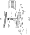
Fig. 1 is an exemplary diagram illustrating a system for additive manufacturing. -
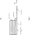
Fig. 2 is an exemplary cross-sectional diagram illustrating an embodiment of a structure during manufacturing using the system ofFig. 1 , wherein the structure includes a first layer structure. -
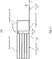
Fig. 3 is an exemplary cross-sectional diagram illustrating an alternative embodiment of the structure ofFig. 2 during manufacturing, wherein a support structure is positioned adjacent to the structure. -
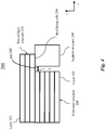
Fig. 4 is an exemplary cross-sectional diagram illustrating an alternative embodiment of the structure ofFig. 3 during manufacturing, wherein a second layer structure is printed on the support structure. -
Fig. 5 is an exemplary cross-sectional diagram illustrating an alternative embodiment of the structure ofFig. 4 during manufacturing, wherein the support structure is removed from the second layer structure. -
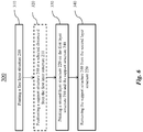
Fig. 6 is an exemplary top-level flow chart illustrating an embodiment of a method for additive manufacturing based on the system ofFig. 1 . -
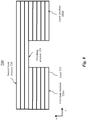
Fig. 7 is an exemplary cross-sectional diagram illustrating an alternative embodiment of the structure ofFig. 4 , wherein the support structure is between two first layer structures. -
Fig. 8 is an exemplary cross-sectional diagram illustrating an alternative embodiment of the structure ofFig. 7 , wherein the support structure is removed from the second layer structure. -
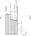
Fig. 9 is an exemplary cross-sectional diagram illustrating an alternative embodiment of the structure ofFig. 5 , wherein the first layer structure has a tilted sidewall. -
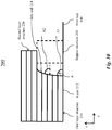
Fig. 10 is an exemplary cross-sectional diagram illustrating another alternative embodiment of the structure ofFig. 5 , wherein the first layer structure has a curved sidewall. -
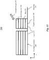
Fig. 11 is an exemplary cross-sectional diagram illustrating another alternative embodiment of the structure ofFig. 5 , wherein the second layer structure has a slant angle. -
Fig. 12 is an exemplary cross-sectional diagram illustrating an alternative embodiment of the structure ofFig. 3 , wherein the support structure includes a release layer. -
Fig. 13 is an exemplary cross-sectional diagram illustrating an alternative embodiment of the structure ofFig. 3 , wherein compressed gas is sprayed onto the support structure. -
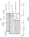
Fig. 14 is an exemplary cross-sectional diagram illustrating an alternative embodiment of the structure ofFig. 13 , wherein the support structure includes a release layer. -
Fig. 15 is an exemplary cross-sectional diagram illustrating another alternative embodiment of the structure ofFig. 3 , wherein the support structure includes one or more offset layers. -
Fig. 16 is an exemplary cross-sectional diagram illustrating an alternative embodiment of the structure ofFig. 4 , wherein the structure includes a third layer structure. -
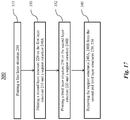
Fig. 17 is an exemplary flow chart illustrating an alternative embodiment of the method for additive manufacturing ofFig. 6 . -
Fig. 18 is an exemplary perspective diagram illustrating an embodiment of a vehicle body manufactured using the method ofFig. 17 . -
Fig. 19 is an exemplary detail drawing illustrating an embodiment of a chassis of the vehicle body ofFig. 18 . -
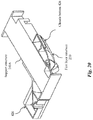
Fig. 20 is an exemplary detail drawing illustrating an alternative embodiment of the chassis ofFig. 19 during manufacturing, wherein a first layer structure is printed. -
Fig. 21 is an exemplary detail drawing illustrating an alternative embodiment of the chassis ofFig. 20 during manufacturing, wherein a second layer structure is printed. -
Fig. 22 is an exemplary detail drawing illustrating an alternative embodiment of the chassis ofFig. 21 during manufacturing, wherein a third layer structure is printed. -
Fig. 23 is an exemplary detail drawing illustrating an alternative embodiment of the chassis ofFig. 22 during manufacturing, wherein support structures are removed from the chassis. -
Fig. 24 is an exemplary diagram illustrating an embodiment of a control system for controlling the system ofFig. 1 . - It should be noted that the figures are not drawn to scale and that elements of similar structures or functions are generally represented by like reference numerals for illustrative purposes throughout the figures. It also should be noted that the figures are only intended to facilitate the description of the preferred embodiments. The figures do not illustrate every aspect of the described embodiments and do not limit the scope of the present disclosure.
-
Fig. 1 shows anexemplary system 100 for additive manufacturing. Thesystem 100 can print 3D articles via extrusion deposition (or material extrusion). Aprint head 120 is shown as including a nozzle configured to deposit one or more polymer layers onto aprint bed 140 to form the 3D printed article. Theprint bed 140 can include a heated table and/or previously deposited layers. The stacking direction of the layers is z-direction and the printing direction is the x-direction. - Although
Fig. 1 shows additive manufacturing as being implemented by thesystem 100 using extrusion deposition, any other systems or processes for implementing additive manufacturing can be used in the present disclosure. Exemplary processes for additive manufacturing can include binder jetting, directed energy deposition, material jetting, powder bed fusion, sheet lamination, vat photopolymerization, stereolithography, or a combination thereof. - Since currently-available methods and systems are incapable of producing large-scale additively manufactured parts with strong overhang structures, additively manufactured structures with strong overhang structures and method for making the same can prove desirable and provide a basis for a wide range of applications, such as additive manufacturing for vehicles and/or architectural structures.
- Although the structures and methods as set forth in the present disclosure are applied to solve technical problems in large-scale additive manufacturing, the structures and methods can be applied to any smaller-scale additive manufacturing, such as medium-scale and/or small-scale additive manufacturing, without limitation.
- Turning to
Fig. 2 , a cross section of astructure 200 is shown. Thestructure 200 can include afirst layer structure 210 including one or more layers (or first layers) 212 being stacked in the z direction. Thefirst layer structure 210 can be manufactured using additive manufacturing. - The
first layer structure 210 is shown as having asidewall 214. Thesidewall 214 is shown as being at a side angle A relative to the x-direction. Stated somewhat differently, thesidewall 214 is at the side angle A relative to theprint bed 140. - Turning to
Fig. 3 , asupport structure 240 is positioned at a distance d from thesidewall 214. AlthoughFig. 3 shows thesupport structure 240 and thefirst layer structure 210 as being placed on theprint bed 140, thesupport structure 240 and/or thefirst layer structure 210 can be positioned on any uniform and/or different planes, without limitation. - The
support structure 240 is shown as having an interfacingside 246 that is distal to theprint bed 140. Thefirst layer structure 210 can include aninterfacing side 216 distal to theprint bed 140. As shown inFig. 3 for illustrative purposes, the interfacingside side side print bed 140. - The distance d can be spacing between any points on the
first layer structure 210 and thesupport structure 240. As illustratively shown inFig. 3 , the distance d can be size of agap 242 between the interfacingsides support structure 240 and thefirst layer structure 210 that subsequent layers can be printed on. -
Fig. 3 shows thegap 242 to be uniform for illustrative purposes only. Thegap 242 can be uniform and/or different at various locations along thesidewall 214. For example, thesidewall 214 can have a curved, slanted and/or irregular shape, resulting in anon-uniform gap 242 and a non-uniform distance d along thesidewall 214. In one example, the distance d can be zero and/or non-zero at different locations. In other words, thesidewall 214 can be partially in contact with thesupport structure 240. - The
support structure 240 can have any selected shape and size. Thesupport structure 240 can be made using any suitable materials and processes. In one embodiment, thesupport structure 240 can be made using 3D printing. Advantageously, 3D printing can make thesupport structure 240 that has complex contour. In one example, thesupport structure 240 can be printed on theprint bed 140 and placed upside down during usage. Advantageously, thesupport structure 240 can provide theinterfacing side 246 that is planar. - Additionally and/or alternatively, the
support structure 240 can be at least partially made of foam. The foam can be machined to obtain selected size and shape. Advantageously, thesupport structure 240 can be made in a less expensive manner. - Although
Fig. 3 shows thefirst layer structure 210 and thesupport structure 240 having thegap 242 in a plane defined by z- and x-directions, thefirst layer structure 210 and thesupport structure 240 can be separated and/or in contact in a plane defined by z- and y-directions and/or any other planes, without limitation. - Turning to
Fig. 4 , asecond layer structure 220 is shown as being disposed on thesupport structure 240 and thefirst layer structure 210. Thesecond layer structure 220 is shown as including one or more layers (or second layers) 222 being stacked in the z direction. In one embodiment, thesecond layer structure 220 can be manufactured using the same additive manufacturing techniques that manufactures thefirst layer structure 210. - The
second layer structure 220 is shown as spanning thegap 242. The distance d can be any suitable lengths. A small distance d can advantageously reduce possibility of deformation of thesecond layer structure 220 that spans the gap. The distance d can be determined by bridging capability of thesecond layer structure 220, that is, ability of the material of thesecond layer structure 220 to overhang without any support in a vertical direction from space below thesecond layer structure 220. In one embodiment, the distance d can be zero. Advantageously, thesecond layer structure 220 can be fully supported during printing and deformation can be reduced or prevented. - Turning to
Fig. 5 , thesupport structure 240 is shown as being removed from thesecond layer structure 220. The portion of thesecond layer structure 220 that extends beyond thefirst layer structure 210 is anoverhang structure 224. - The
overhang structure 224 can maintain shape before and after removal of thesupport structure 240. Stated somewhat differently, even though being unsupported and positioned on empty space, theoverhang structure 224 does not deform or break away from thesecond layer structure 220 under gravity. - Turning to
Fig. 6 , anexemplary method 300 of manufacturing the structure 200 (shown inFig. 5 ) is shown. Thefirst layer structure 210 can be printed, at 310. Thesecond layer structure 220 can be printed, at 330, on thesupport structure 240 and thefirst layer structure 210. - The
support structure 240 can be removed, at 340, from thesecond layer structure 220. Removing thesupport structure 240 from thesecond layer structure 220 can include detaching thesupport structure 240 from direct contact with thesecond layer structure 220. Thesupport structure 240 can be removed at any suitable time. In one embodiment, thesecond layer structure 220 can be cooled to room temperature and/or solidified before thesupport structure 240 is removed from thesecond layer structure 220. Advantageously, thesupport structure 240 can provide support to thesecond layer structure 220 during the cooling and/or solidification to avoid deformation of thesecond layer structure 220. Upon completion of the cooling and/or solidification, thesecond layer structure 220 can gain sufficient structural strength and does not deform even after thesupport structure 240 is removed. - Advantageously, the
support structure 240 can be reused for repeatedly making thestructure 200. The reuse can significantly save material, printing time and energy. Furthermore, because thesupport structure 240 can be separated from thestructure 200, thesupport structure 240 can be made with materials with a high density to provide sufficient strength to support thesecond layer structure 220 but still does not increase weight of thestructure 200. - Optionally, the
support structure 240 can be positioned, at 320, at the selected distance d from thefirst layer structure 210. In one embodiment, thesupport structure 240 can be positioned after printing thefirst layer structure 210 and before printing thesecond layer structure 220. For example, the printing process can have a pause or time interval after printing thefirst layer structure 210 and before printing thesecond layer structure 220. Thesupport structure 240 can be positioned during the time interval manually by an operator and/or in a machine-assisted manner (for example, robotically). Advantageously, thesupport structure 240 does not impede the process of printing thefirst layer structure 210. Additionally and/or alternatively, thesupport structure 240 can be placed prior to finishing the printing of thefirst layer structure 210. The process of positioning thesupport structure 240 can be significantly shorter than the process of printing thefirst layer structure 210. - Turning to
Fig. 7 , thefirst layer structure 210 is shown as includingfirst layer structures first layer structures more layers 212 being stacked in the z direction. Thefirst layer structures layers 212. In one embodiment, thefirst layer structures layers 212. Advantageously thefirst layer structures first layer structures -
Fig. 7 shows thesupport structure 240 as being located between thefirst layer structures support structure 240 is shown as being at distances d1, d2 from thefirst layer structures Fig. 7 shows thesecond layer structure 220 as being disposed on thefirst layer structures support structure 240. - Turning to
Fig. 8 , thesupport structure 240 is shown as being removed from thesecond layer structure 220. Theoverhang structure 224 is shown as spanning between thefirst layer structures overhang structure 224 can maintain shape before and after removal of thesupport structure 240. Stated somewhat differently, theoverhang structure 224 can bridge thefirst layer structures - Turning to
Fig. 9 , theside wall 214 of thefirst layer structure 210 is shown as being a surface that tilts away from the z-direction. Stated somewhat differently, the side angle A is not a right angle.Fig. 9 shows the side angle A as being smaller than 90 degrees. - The side angle A can have any suitable values. The minimum value of the side angle A can be determined by the printing process. In one embodiment, when beads (not shown) for printing the
first layer structure 210 are wide, the side angle A can be small. For example, when the beads have a great aspect ratio, the side angle A can be small. The aspect ratio can include a width (or size in x-direction) to height (or size in z-direction) ratio of the bead. Additionally and/or alternatively, when there is great solidification time between thelayers 212, the side angle A can be small. An exemplary side angle A can range from 35 degrees to 90 degrees, from 40 degrees to 90 degrees, or from 45 degrees to 90 degrees. - Turning to
Fig. 10 , theside wall 214 of thefirst layer structure 210 is shown as including a curved surface tilting away from the z-direction. Theside wall 214 can have a plurality of side angles A at respective locations along theside wall 214. As illustrated inFig. 10 , the side angles A are shown as including a side angle A1 at an end region of theside wall 214 and a side angle A2 at a middle region of theside wall 214. - The minimum value of each of the side angles A1, A2 can be determined by the bridging capability of the
first layer structure 210. In one embodiment, when beads (not shown) for printing thefirst layer structure 210 are wide, the side angles A1, A2 can be small. For example, when the beads have a great aspect ratio, the side angles A1, A2 can be small. The aspect ratio can include a width (or size in x-direction) to height (or size in z-direction) ratio of the bead. Additionally and/or alternatively, when there is great solidification time between thelayers 212, the side angles A1, A2 can be small. Exemplary side angles A1, A2 can each range from 35 degrees to 90 degrees, from 40 degrees to 90 degrees, or from 45 degrees to 90 degrees. - Although the
side wall 214 is shown as being straight inFig. 9 and curved inFig. 10 , theside wall 214 can be straight, curved, or a combination thereof, without limitation. - Turning to
Fig. 11 , the interfacingside 246 is shown as interfacing with thesecond layer structure 220. Morphology and/or shape of theinterfacing side 246 can determine thesecond layer structure 220 that is printed on thesupport structure 240. -
Fig. 11 shows a slant angle B as existing between the interfacingside 246 and theprint bed 140. Effectively, theoverhang structure 224 formed on thesupport structure 240 can have a side wall at the slant angle B relative to theprint bed 140. - The slant angle B can have any suitable values. In one embodiment, the slant angle B can have a value that is difficult and/or impossible to achieve in 3D printing without using the
support structure 240. An exemplary slant angle B can range from 0 degrees to 45 degrees. Advantageously, when thesecond layer structure 220 is made of a material that has limited bridging capability and cannot form the slant angle B at a small value without any support, thesupport structure 240 can provide support to make such small slant angle B feasible. - In one embodiment, the slant angle B can be zero. The interfacing
side 246 can thus be parallel to theprint bed 140. For example, the interfacingside 246 can be co-planar with the interfacing side 216 (shown inFig. 3 ) of thefirst layer structure 210. - Turning to
Fig. 12 , thesupport structure 240 is shown as including arelease layer 244 disposed on abase 241 and providing theinterfacing side 246. Therelease layer 244 can be disposed before the second layer structure 220 (shown inFig. 4 ) is printed on thesupport structure 240. - The
release layer 244 can be used to prevent tight bonding between thesecond layer structure 220 and thesupport structure 240. Advantageously, after thesecond layer structure 220 is cooled and/or solidified, thesupport structure 240 can be removed from thesecond layer structure 220 without damaging thesecond layer structure 220. Additionally and/or alternatively, therelease layer 244 can be used for providing sufficient adhesion between thesecond layer structure 220 and thesupport structure 240 during printing of thesecond layer structure 220. Advantageously, thesecond layer structure 220 can be fixed to thesupport structure 240 to prevent positional shift between thesecond layer structure 220 and thesupport structure 240. Anexemplary release layer 244 can include a non-sticking material. For example, therelease layer 244 can include talcum powder, mica dust, oil, such as cooking oil, and/or mold release material. Alternatively and/or additionally, therelease layer 244 can be at least partially made of soapstone. For example, therelease layer 244 can be applied by using a soapstone marker. Advantageously, application of therelease layer 244 can be a cleaner process than applying loose powder. - Additionally and/or alternatively, the
release layer 244 can include a sheet and/or a coating providing the properties as set forth above. Exemplary sheet can include acrylonitrile butadiene styrene (ABS) sheet, other thermoplastic sheets, cloth fabric coated in contact adhesive, bead boards, medium-density fibreboard (MDF) board covered in wood glue (or bead board without the pellets sprinkled on top of the bead board), foam inserts, cardboard, or a combination thereof. - Although
Fig. 12 shows therelease layer 244, desired surface interaction between thesecond layer structure 220 and thesupport structure 240 can be achieved without therelease layer 244. In one embodiment, thesecond layer structure 220 and thesupport structure 240 can be made of materials that are different. For example, thesecond layer structure 220 and thesupport structure 240 can be made of first and second materials, respectively. The first and second materials can have chemical and/or physical properties of sufficient difference to achieve advantageous interface interactions that are the same as and/or greater than the interactions provided by talcum powder. - In one embodiment, each of the first and second materials can include ABS, carbon fiber-filled ABS (CF/ABS), polycarbonate, polyamide, poly(p-phenylene oxide) (PPO), poly(p-phenylene ether) (PPE), or a combination thereof. For example, the CF/ABS can include discontinuous carbon fiber composite such as 20% chopped carbon fiber-filled acrylonitrile butadiene styrene (20% CF/ABS). Additionally and/or alternatively, the first material can include ABS and/or co-polyester, and can be filled with carbon fibers and/or graphene nanofillers. The second material can be different from the first material. In one example, the first material can include ABS, and the second material can include PPO.
- Additionally and/or alternatively, the first and second materials can have different temperatures during printing of the
second layer structure 220 on thesupport structure 240. The temperature difference between the first and second materials can facilitate release between the first and second materials when the first material is the same as, or different from, the second material. For example, the first and second materials can include the same materials but a temperature of the second material can be lower than a temperature of the first material during printing of thesecond layer structure 220. Advantageously, desired release properties between thesecond layer structure 220 and thesupport structure 240 can be achieved. - Turning to
Fig. 13 , thesupport structure 240 is shown as including one ormore layers 212 being stacked in the z direction. In one embodiment, thesupport structure 240 can be made using additive manufacturing. For example, thesupport structure 240 can be made using 3D printing and concurrently with thefirst layer structure 210. Stated somewhat differently, a computerized model can be generated to include thefirst layer structure 210 and thesupport structure 240, and thefirst layer structure 210 and thesupport structure 240 can be printed in one printing process. -
Fig. 13 shows thatcompressed gas 243 can optionally be sprayed on thesupport structure 240 to reduce the temperature of thesupport structure 240 during and/or before the printing of the second layer structure 220 (shown inFig. 4 ). Thecompressed gas 243 can include any gas kept under a pressure that is greater than atmospheric pressure. Exemplarycompressed gas 243 can include compressed air, liquid nitrogen, or a combination thereof. - The newly printed
support structure 240 can have theinterfacing side 246 that is at a high temperature. Thecompressed gas 243 can cool down theinterfacing side 246. Thesecond layer structure 220 can, at a temperature higher than the temperature of theinterfacing side 246, be printed on thesupport structure 240 and be easily released subsequently even though the release layer 244 (shown inFig. 12 ) is not applied to thesupport structure 240. Advantageously, thefirst layer structure 210 is not cooled down by thecompressed gas 243, so good adhesion between the first andsecond layer structures - Turning to
Fig. 14 , thecompressed gas 243 is shown as being, optionally, sprayed on thesupport structure 240 to reduce the temperature of thesupport structure 240. For example, thesupport structure 240 can be made via additive manufacturing, and the newly printedsupport structure 240 can be at a high temperature. Thecompressed gas 243 can reduce the temperature of thesupport structure 240. - The
release layer 244 can be applied to thesupport structure 240. Therelease layer 244 can be made of soapstone, talcum powder and/or any other materials that can facilitate release of thesupport structure 240. Thesecond layer structure 220 can, at a temperature higher than the temperature of thesupport structure 240, be printed on thesupport structure 240. Advantageously, thesecond layer structure 220 can be more easily released from thesupport structure 240. - Turning to
Fig. 15 , thesupport structure 240 is shown as including one or more offsetlayers 248 disposed distal to theprint bed 140. The offset layers 248 can have uniform and/or different thicknesses and/or morphologies. The offset layers 248 can be selected to tune a height and/or shape of thesupport structure 240 such that the interfacingside 246 can be at a desired position relative to thefirst layer structure 210. For example, the offsetlayers 248 can be selected such that the interfacingside 246 of thesupport structure 240 is co-planar with the interfacingside 216 of thefirst layer structure 210. - When the
support structure 240 is re-used in multiple printing processes, thefirst layer structures 210 in each printing process can have different degrees of deformation, resulting in different shapes and/or thicknesses. By fixing selected offsetlayers 248 on thesupport structure 240, size, thickness, and/or shape of thesupport structure 240 can advantageously be adjusted to precisely match, and/or be aligned with, geometry of each of thefirst layer structures 210. - The offset layers 248 can be made of a third material. The second and third materials can be uniform and/or different. For example, the offset
layers 248 can be made of foam and can be shaped to be similar to a shim. - Although
Fig. 15 shows two offsetlayers 248 for illustrative purposes only, thesupport structure 240 can include one or more offsetlayers 248 having uniform and/or different geometry, without limitation. AlthoughFig. 15 shows the offsetlayers 248 being stacked in z-direction, the offsetlayers 248 can be arranged in any directions, without limitation. - Turning to
Fig. 16 , thesupport structure 240 is shown as including a support structure (or a first support structure) 240A and a support structure (or a second support structure) 240B stacked on thesupport structure 240A. Thesupport structure 240B is shown as having an interfacingside 246B that is more distal to theprint bed 140 than an interfacingside 246A of thesupport structure 240A. Thestructure 200 is shown as including athird layer structure 230 formed on thesecond layer structure 220 and on thesupport structure 240B. Thethird layer structure 230 is shown as including one or more layers (or third layers) 232 being stacked in the z direction. Upon removal of thesupport structure 240,overhang structures - Although
Fig. 16 shows thesupport structure 240B as being stacked on thesupport structure 240A, thesupport structure 240B can be located on any surface, such as theprint bed 140 and/or on any previously-printed layers, without limitation. AlthoughFig. 16 showssupport structures support structures 240 of uniform and/or different thicknesses and/or shapes can be used. - Turning to
Fig. 17 , theexemplary method 300 of manufacturing the structure 200 (shown inFig. 16 ) is shown. Thefirst layer structure 210 can be printed, at 310. Thesecond layer structure 220 can be printed, at 330, on thefirst layer structure 210 and thesupport structure 240A. Thethird layer structure 230 can be printed, at 332, on thesecond layer structure 220 and thesupport structure 240B. Thesupport structures third layer structures - Stated somewhat differently, the printing at 330 can be repeatedly performed, as shown at 332, by positioning
additional support structures 240 to print on, to create multiple overhang structures at different height and/or distances from the print bed 140 (shown inFig. 16 ). Although shown as being repeatedly performed once inFig. 17 , the printing at 330 can be repeatedly performed for any number of times, without limitation. - Turning to
Fig. 18 , anexemplary automobile body 400 is shown as including achassis 420 at a bottom of thebody 400. Thechassis 420 can be made via additive manufacturing by using the disclosed method 300 (shown inFig. 17 ). - The
chassis 420 is shown as including achassis bottom 426. Thechassis 420 further includes a suspension assembly mount location 422 and afender 428 each raising above thechassis bottom 426. Stated somewhat differently, the suspension assembly mount location 422 and thefender 428 can both be farther from ground than thechassis bottom 426. Thefender 428 is shown as including afender top 424 that raises farther from ground than the suspension assembly mount location 422.Fig. 19 shows a close-up view of thechassis 420. - Turning to
Fig. 20 , at least a portion of thechassis 420 is shown as being made during a printing process. Thefirst layer structure 210 is printed and is shown as including thechassis bottom 426. Thesupport structure 240A is shown as being inserted in thefirst layer structure 210. Stated somewhat differently, the chassis bottom is shown as including twofirst layer structures 210; thesupport structure 240A can be inserted between the twofirst layer structures 210. A surface of thesupport structure 240A can be coplanar with a surface of thechassis bottom 426. - The
support structure 240A can be inserted in thefirst layer structure 210 during the printing process and can take a short time without significantly affecting speed of production. For example, the printing can be paused for a time interval ranging from 30 seconds to 60 seconds, and thesupport structure 240A can be inserted during the time interval. - Turning to
Fig. 21 , thesecond layer structure 220 is shown as being formed on thefirst layer structure 210 and thesupport structure 240A. A portion of thesecond layer structure 220 can include the suspension assembly mount location 422 (shown inFig. 19 and out of view inFig. 21 ). -
Fig. 21 shows thesecond layer structure 220 as defining afender top opening 423. Directly printing the fender top 424 (shown inFig. 19 ) can require significant bridging capability that the printing material may not possess. In one embodiment, height of thesecond layer structure 220 can at least partially be determined by the size of the portion of thefender 428 that can be printed with the bridging capability of the printing material. When the printing material has great bridging capability, thesecond layer structure 220 can include a significant portion of thefender 428, and the fender top opening 423 can be small. - Turning to
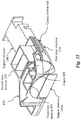
Fig. 22 , thethird layer structure 230 is shown as being formed on thesecond layer structure 220 and thesupport structure 240B. The first, second and third layer structures 210-230 are shown in wire-frame for easy viewing.Fig. 20 shows thesupport structure 240B as including a rectangular box or rectangular hexahedron and being stacked on thesupport structure 240A. Thethird layer structure 230 includes thefender top 424 that is printed on thesupport structure 240B. - The
support structure 240B can be positioned in the fender top opening 423 (shown inFig. 21 ) during the printing process and can take a short time without significantly affecting speed of production. For example, the printing can be paused for a time interval ranging from 30 seconds to 60 seconds, and thesupport structure 240B can be inserted during the time interval. - Turning to
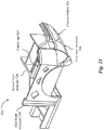
Fig. 23 , thesupport structures Fig. 22 ) are shown as having been removed from the second andthird layer structures chassis 420 can thus be formed. - The disclosed embodiments further disclose a structure 200 (shown in
Fig. 5 ) that is made via additive manufacturing. Thestructure 200 can include the first layer structure 210 (shown inFig. 5 ) having the sidewall 214 (shown inFig. 5 ). Thestructure 200 can include the second layer structure 220 (shown inFig. 5 ) stacked on thefirst layer structure 210 in the z-direction. Stated somewhat differently, the first andsecond structures second layer structure 220 can include the overhang structure 224 (shown inFig. 5 ) extending beyond thesidewall 214 and unsupported in the stacking direction. The disclosed embodiments further discloses thestructure 200 as shown inFigs. 7-11 ,16 and18-23 . - Turning to
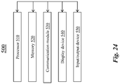
Fig. 24 , acontrol system 500 for additive manufacturing is shown. Thecontrol system 500 can be configured for controlling the print head 120 (shown inFig. 1 ). Thecontrol system 500 can include aprocessor 510. Theprocessor 510 can include one or more general-purpose microprocessors (for example, single or multi-core processors), application-specific integrated circuits, application-specific instruction-set processors, graphics processing units, physics processing units, digital signal processing units, coprocessors, network processing units, encryption processing units, and the like. - The
processor 510 can execute instructions for implementing thecontrol system 500 and/or computerized model of the structure 200 (shown inFig. 5 ). In an un-limiting example, the instructions includes one or more additive manufacturing software programs. The programs can operate to control thesystem 100 with multiple printing options, settings and techniques for implementing additive printing of large components. - The programs can include a computer-aided design (CAD) program to generate a 3D computer model of the
structure 200. Additionally and/or alternatively, the 3D computer model can be imported from another computer system (not shown). The 3D computer model can be solid, surface or mesh file format in an industry standard. - The programs can load the 3D computer model, create a print model and generate the machine code for controlling the
system 100 to print thestructure 200. Exemplary programs can include LSAM Print 3D, available from Thermwood Corporation located in Dale, Indiana. Additionally and/or alternatively, exemplary programs can include Unfolder Module Software, Bend Simulation Software, Laser Programming and/or Nesting Software available from Cincinnati Incorporated located in Harrison, Ohio. - As shown in
Fig. 24 , thecontrol system 500 can include one or more additional hardware components as desired. Exemplary additional hardware components include, but are not limited to, a memory 520 (alternatively referred to herein as a non-transitory computer readable medium).Exemplary memory 520 can include, for example, random access memory (RAM), static RAM, dynamic RAM, read-only memory (ROM), programmable ROM, erasable programmable ROM, electrically erasable programmable ROM, flash memory, secure digital (SD) card, and/or the like. Instructions for implementing thecontrol system 500 and/or computerized model of thestructure 200 can be stored on thememory 520 to be executed by theprocessor 510. - Additionally and/or alternatively, the
control system 500 can include acommunication module 530. Thecommunication module 530 can include any conventional hardware and software that operates to exchange data and/or instruction between thecontrol system 500 and another computer system (not shown) using any wired and/or wireless communication methods. For example, thecontrol system 500 can receive computer-design data corresponding to thestructure 200 via thecommunication module 530. Exemplary communication methods include, for example, radio, Wireless Fidelity (Wi-Fi), cellular, satellite, broadcasting, or a combination thereof. - Additionally and/or alternatively, the
control system 500 can include adisplay device 540. Thedisplay device 540 can include any device that operates to present programming instructions for operating thecontrol system 500 and/or present data related to theprint head 120. Additionally and/or alternatively, thecontrol system 500 can include one or more input/output devices 550 (for example, buttons, a keyboard, keypad, trackball), as desired. - The
processor 510, thememory 520, thecommunication module 530, thedisplay device 540, and/or the input/output device 550 can be configured to communicate, for example, using hardware connectors and buses and/or in a wireless manner. - The disclosed embodiments are susceptible to various modifications and alternative forms, and specific examples thereof have been shown by way of example in the drawings and are herein described in detail. It should be understood, however, that the disclosed embodiments are not to be limited to the particular forms or methods disclosed, the scope of protection being defined by the claims.
Claims (15)
- A method for additive manufacturing, comprising:forming at least one first layer structure (210);forming a second layer structure (220) on the first layer structure (210) and a first support structure (240A);removing the first support structure (240A) from the second layer structure (220);characterized byforming, before said removing the first support structure (240A), a third layer structure (230) on the second layer structure (220) and a second support structure (240B), the second support structure (240B) being located at least partially on the first support structure (240A); andremoving the second support structure (240B) from the third layer structure (230),whereinsaid forming the at least one first layer structure (210) includes forming a chassis bottom (426);said forming the second layer structure (220) includes forming a fender (428) and a suspension assembly mount location (422) each connected to the chassis bottom (426), the fender (428) defining a fender top opening (423); andsaid forming the third layer structure (230) includes forming a fender top (424) on the second support structure (240B) and covering the fender top opening (423).
- The method of claim 1, wherein said forming the second layer structure includes forming an overhang structure (224) at least partially supported by the first support structure during said forming.
- The method of claim 1 or claim 2, wherein said forming the at least one first layer structure includes forming two first layer structures (210A, 210B) the first support structure being located between the two first layer structures.
- The method of claim 3, wherein said forming the second layer structure includes forming the second layer structure bridging the two first layer structures and at least partially supported by the first support structure during said forming the second layer structure.
- The method of any one of claims 1-4, wherein a gap exists between the first support structure and the at least one first layer structure during said forming the second layer structure.
- The method of any one of claims 1-5, wherein the first support structure is not in contact with the at least one first layer structure during said forming the second layer structure.
- The method of claim 6, wherein said forming the second layer structure includes forming the second layer structure that bridges the first support structure and the at least one first layer structure.
- The method of any one of claims 1-7, wherein:said forming the at least one first layer structure includes printing one or more first layers in a printing direction, the one or more first layers being stacked in a stacking direction perpendicular to the printing direction; andsaid forming the second layer structure includes printing one or more second layers in the printing direction, the one or more second layers being stacked in the stacking direction.
- The method of claim 8, wherein said forming the at least one first layer structure includes forming a first layer structure having a side wall at a side angle relative to the printing direction, the side angle ranging from 35 degrees to 90 degrees.
- The method of claim 8 or claim 9, wherein said forming the at least one first layer structure includes forming a first layer structure having the side wall (214) with the side angle varying along the side wall.
- The method of claim 10, wherein said forming the at least one first layer structure includes forming the first layer structure having the side wall that is curved, with the side angle decreasing along the stacking direction.
- The method of any one of claims 1-11, further comprising positioning the first support structure at a selected distance from the at least one first layer structure after said forming the at least one first layer structure and before said forming the second layer structure.
- The method of claim 12, wherein the at least one first layer structure and the first support structure respectively have interfacing sides (246, 216), proximal to the second layer structure, and said positioning includes positioning the first support structure such that the interfacing sides are coplanar.
- The method of any one of claims 1-13, further comprising positioning the first support structure in a slot defined in the chassis bottom before said forming the second layer structure.
- The method of any one of claims 1-14, further comprising positioning the second support structure on the first support structure and aligned with the fender top opening before said forming the third layer structure.
Priority Applications (1)
| Application Number | Priority Date | Filing Date | Title |
|---|---|---|---|
| EP21203820.2A EP3964351A1 (en) | 2018-01-23 | 2019-01-23 | Additively manufactured structure and method for making the same |
Applications Claiming Priority (2)
| Application Number | Priority Date | Filing Date | Title |
|---|---|---|---|
| US201862620891P | 2018-01-23 | 2018-01-23 | |
| PCT/US2019/014792 WO2019147700A1 (en) | 2018-01-23 | 2019-01-23 | Additively manufactured structure and method for making the same |
Related Child Applications (2)
| Application Number | Title | Priority Date | Filing Date |
|---|---|---|---|
| EP21203820.2A Division-Into EP3964351A1 (en) | 2018-01-23 | 2019-01-23 | Additively manufactured structure and method for making the same |
| EP21203820.2A Division EP3964351A1 (en) | 2018-01-23 | 2019-01-23 | Additively manufactured structure and method for making the same |
Publications (2)
| Publication Number | Publication Date |
|---|---|
| EP3743262A1 EP3743262A1 (en) | 2020-12-02 |
| EP3743262B1 true EP3743262B1 (en) | 2021-12-01 |
Family
ID=65352185
Family Applications (2)
| Application Number | Title | Priority Date | Filing Date |
|---|---|---|---|
| EP19704165.0A Active EP3743262B1 (en) | 2018-01-23 | 2019-01-23 | Additively manufactured structure and method for making the same |
| EP21203820.2A Withdrawn EP3964351A1 (en) | 2018-01-23 | 2019-01-23 | Additively manufactured structure and method for making the same |
Family Applications After (1)
| Application Number | Title | Priority Date | Filing Date |
|---|---|---|---|
| EP21203820.2A Withdrawn EP3964351A1 (en) | 2018-01-23 | 2019-01-23 | Additively manufactured structure and method for making the same |
Country Status (9)
| Country | Link |
|---|---|
| US (1) | US11584065B2 (en) |
| EP (2) | EP3743262B1 (en) |
| JP (2) | JP2021511990A (en) |
| KR (1) | KR20200118819A (en) |
| CN (1) | CN111989211A (en) |
| CA (1) | CA3089364C (en) |
| DK (1) | DK3743262T3 (en) |
| MX (1) | MX2020007791A (en) |
| WO (1) | WO2019147700A1 (en) |
Cited By (1)
| Publication number | Priority date | Publication date | Assignee | Title |
|---|---|---|---|---|
| WO2023117702A1 (en) * | 2021-12-21 | 2023-06-29 | REHAU Industries SE & Co. KG | Method for producing a component by means of additive manufacturing |
Families Citing this family (21)
| Publication number | Priority date | Publication date | Assignee | Title |
|---|---|---|---|---|
| US10967576B2 (en) | 2017-11-10 | 2021-04-06 | Local Motors IP, LLC | Additive manufactured structure having a plurality of layers in a stacking direction and method for making the same |
| JP2022501209A (en) | 2018-04-23 | 2022-01-06 | ローカル モーターズ アイピー, エルエルシーLocal Motors Ip, Llc | Methods and equipment for additive manufacturing |
| US11731342B2 (en) | 2018-04-23 | 2023-08-22 | Rapidflight Holdings, Llc | Additively manufactured structure and method for making the same |
| EP3797026A4 (en) | 2018-05-22 | 2022-03-02 | Mantle Inc. | METHOD AND SYSTEM FOR AUTOMATIC TOOLWAY GENERATION |
| EP3833533B1 (en) * | 2018-08-09 | 2024-06-26 | University of Maine System Board of Trustees | Non-orthogonal additive manufacturing and the treatment of parts manufactured thereof |
| KR102035454B1 (en) * | 2019-04-24 | 2019-10-22 | 전자부품연구원 | 3D Print Slicing Method for Resolving Quantization Error |
| WO2021029868A1 (en) | 2019-08-12 | 2021-02-18 | Local Motors IP, LLC | Additively manufactured structure and method for making the same |
| US11813790B2 (en) * | 2019-08-12 | 2023-11-14 | Rapidflight Holdings, Llc | Additively manufactured structure and method for making the same |
| CN110605391B (en) * | 2019-09-09 | 2021-08-27 | 江西宝航新材料有限公司 | 3D printing additive manufacturing method of pot-shaped thin-walled workpiece |
| WO2021067450A1 (en) * | 2019-09-30 | 2021-04-08 | Evolve Additive Solutions, Inc. | Additive manufacturing system and method with improved surface finish |
| CN111361152B (en) * | 2020-04-07 | 2025-04-22 | 上海市机械施工集团有限公司 | Platform device suitable for 3D printing and manufacturing process of upper printing plate thereof |
| DE102020209968A1 (en) | 2020-08-06 | 2022-02-10 | Robert Bosch Gesellschaft mit beschränkter Haftung | Method of making an electrical and a mechanical connection |
| DE102020209967A1 (en) | 2020-08-06 | 2022-02-10 | Robert Bosch Gesellschaft mit beschränkter Haftung | Process for manufacturing a housing for an energy converter |
| JP7534636B2 (en) * | 2021-01-29 | 2024-08-15 | キョーラク株式会社 | Manufacturing method of the object |
| JP7793945B2 (en) * | 2021-11-08 | 2026-01-06 | 株式会社大林組 | Structure and method for forming the structure |
| CN114559660B (en) * | 2022-03-01 | 2023-06-30 | 深圳市创想三维科技股份有限公司 | Model supporting point setting method and device, electronic equipment and readable storage medium |
| WO2023220447A2 (en) * | 2022-05-13 | 2023-11-16 | Firestorm Labs, Inc. | Mission-adaptable aerial vehicle and methods for in-field assembly and use |
| WO2023236963A1 (en) * | 2022-06-09 | 2023-12-14 | 影石创新科技股份有限公司 | Unmanned aerial vehicle |
| DE102022121548A1 (en) * | 2022-08-25 | 2024-03-07 | Tesa Se | Method for printing three-dimensional structures with reduced processing effort |
| WO2025193944A1 (en) | 2024-03-13 | 2025-09-18 | Firestorm Labs, Inc. | Additive manufactured integral fastening system for mission adaptable unmanned aerial vehicles |
| USD1127682S1 (en) | 2024-04-09 | 2026-05-26 | Firestorm Labs, Inc. | Aerial vehicle |
Family Cites Families (23)
| Publication number | Priority date | Publication date | Assignee | Title |
|---|---|---|---|---|
| US5503785A (en) * | 1994-06-02 | 1996-04-02 | Stratasys, Inc. | Process of support removal for fused deposition modeling |
| BR112013031799A2 (en) | 2011-06-15 | 2016-12-20 | Dsm Ip Assets Bv | substrate-based additive manufacturing apparatus and process |
| KR101567267B1 (en) * | 2012-06-19 | 2015-11-06 | 캐논 가부시끼가이샤 | Manufacturing method of structure and manufacturing apparatus |
| US9327350B2 (en) | 2012-08-16 | 2016-05-03 | Stratasys, Inc. | Additive manufacturing technique for printing three-dimensional parts with printed receiving surfaces |
| US9744722B2 (en) | 2012-11-21 | 2017-08-29 | Stratasys, Inc. | Additive manufacturing with polyamide consumable materials |
| US9555582B2 (en) * | 2013-05-07 | 2017-01-31 | Google Technology Holdings LLC | Method and assembly for additive manufacturing |
| US10981680B2 (en) | 2013-10-07 | 2021-04-20 | Shay C. Colson | 3-D printed package customization |
| JP6273849B2 (en) * | 2014-01-15 | 2018-02-07 | セイコーエプソン株式会社 | Three-dimensional structure manufacturing method, three-dimensional structure manufacturing apparatus, and ink set |
| JP2015168202A (en) * | 2014-03-10 | 2015-09-28 | 株式会社リコー | Three-dimensional structure molding system, three-dimensional structure molding control method, and three-dimensional structure molding control program |
| WO2015200280A1 (en) * | 2014-06-23 | 2015-12-30 | Applied Cavitation, Inc. | Systems and methods for additive manufacturing using ceramic materials |
| EP4273263A3 (en) | 2014-07-30 | 2024-01-31 | President and Fellows of Harvard College | Systems and methods for determining nucleic acids |
| US20160207263A1 (en) * | 2015-01-16 | 2016-07-21 | Mark Christopher Gordon | Targeted cooling in a 3d printing system |
| US20160250808A1 (en) * | 2015-02-26 | 2016-09-01 | Mitsubishi Electric Research Laboratories, Inc. | System and Method for Printing Three Dimensional Objects |
| WO2017025956A1 (en) | 2015-08-10 | 2017-02-16 | Stratasys Ltd. | 3d printing using preformed reuseable support structure |
| JP6504064B2 (en) * | 2016-01-21 | 2019-04-24 | トヨタ自動車株式会社 | Method of manufacturing metal member |
| JP6720608B2 (en) * | 2016-03-18 | 2020-07-08 | セイコーエプソン株式会社 | Method for manufacturing three-dimensional model |
| US9718498B1 (en) | 2016-04-08 | 2017-08-01 | Ford Global Technologies, Llc | Vehicular body structure |
| EP3442775B1 (en) * | 2016-04-15 | 2022-07-06 | Materialise NV | Optimized three dimensional printing using ready-made supports |
| US10525628B2 (en) | 2016-04-28 | 2020-01-07 | Wisconsin Alumni Research Foundation | Systems and methods for controlling support structures in manufacturing |
| KR20200016410A (en) * | 2016-08-30 | 2020-02-14 | 리즈 인코포레이티드 | Method of fabricating a three-dimensional object with removable support structure |
| JP6908705B2 (en) * | 2016-12-06 | 2021-07-28 | マークフォージド,インコーポレーテッド | Addition manufacturing by supplying heat bending material |
| CN106626369B (en) | 2017-02-19 | 2019-10-08 | 荆门米丰信息科技有限公司 | Three-dimensional printer and its forming method with backing material molding function |
| US10751800B2 (en) * | 2017-07-25 | 2020-08-25 | Divergent Technologies, Inc. | Methods and apparatus for additively manufactured exoskeleton-based transport structures |
-
2019
- 2019-01-23 WO PCT/US2019/014792 patent/WO2019147700A1/en not_active Ceased
- 2019-01-23 US US16/255,605 patent/US11584065B2/en active Active
- 2019-01-23 CN CN201980019811.7A patent/CN111989211A/en active Pending
- 2019-01-23 KR KR1020207024115A patent/KR20200118819A/en not_active Abandoned
- 2019-01-23 MX MX2020007791A patent/MX2020007791A/en unknown
- 2019-01-23 CA CA3089364A patent/CA3089364C/en active Active
- 2019-01-23 EP EP19704165.0A patent/EP3743262B1/en active Active
- 2019-01-23 DK DK19704165.0T patent/DK3743262T3/en active
- 2019-01-23 JP JP2020561590A patent/JP2021511990A/en active Pending
- 2019-01-23 EP EP21203820.2A patent/EP3964351A1/en not_active Withdrawn
-
2022
- 2022-10-31 JP JP2022174527A patent/JP2023011787A/en active Pending
Cited By (1)
| Publication number | Priority date | Publication date | Assignee | Title |
|---|---|---|---|---|
| WO2023117702A1 (en) * | 2021-12-21 | 2023-06-29 | REHAU Industries SE & Co. KG | Method for producing a component by means of additive manufacturing |
Also Published As
| Publication number | Publication date |
|---|---|
| WO2019147700A1 (en) | 2019-08-01 |
| JP2021511990A (en) | 2021-05-13 |
| EP3743262A1 (en) | 2020-12-02 |
| CA3089364A1 (en) | 2019-08-01 |
| CA3089364C (en) | 2022-11-22 |
| EP3964351A1 (en) | 2022-03-09 |
| US20190224909A1 (en) | 2019-07-25 |
| CN111989211A (en) | 2020-11-24 |
| MX2020007791A (en) | 2020-11-11 |
| US11584065B2 (en) | 2023-02-21 |
| DK3743262T3 (en) | 2022-02-21 |
| KR20200118819A (en) | 2020-10-16 |
| JP2023011787A (en) | 2023-01-24 |
Similar Documents
| Publication | Publication Date | Title |
|---|---|---|
| CA3089364C (en) | Additively manufactured structure and method for making the same | |
| US11813790B2 (en) | Additively manufactured structure and method for making the same | |
| CA3100846C (en) | Additively manufactured structure and method for making the same | |
| EP3784472B1 (en) | Method for additive manufacturing | |
| EP1486318B1 (en) | Method and apparatus for producing an object by solid freeform fabrication | |
| CN101219460A (en) | Process for making reusable tooling | |
| JP2015009495A (en) | Three-dimensional shaped-body and support formation method | |
| CN107790628A (en) | A kind of manufacturing process and device of air blowing solidification method 3D printing casting sand type | |
| KR20010094830A (en) | Variable lamination manufacturing method and apparatus by using linear heat cutting system | |
| JP2015006785A (en) | 3d printer and printing method thereof | |
| US20240359398A1 (en) | Foaming tool | |
| KR20160148075A (en) | An Manufacturing Method of 3 Dimensional Shape | |
| HK40041687A (en) | Additively manufactured structure and method for making the same | |
| HK40041687B (en) | Additively manufactured structure and method for making the same | |
| EP4117919A1 (en) | Additively manufactured structure and method for making the same | |
| CN117120244A (en) | Extrusion-based additive manufacturing: methods, 3D printing systems and 3D parts | |
| US20230191698A1 (en) | Wax base for an object in additive manufacturing | |
| CN102170754B (en) | Method for manufacturing circuit board with superouter fitting | |
| CN111823584B (en) | A hybrid 3D printer and printing method thereof | |
| KR20170099419A (en) | An Manufacturing Method of 3 Dimensional Shape | |
| CN113183417A (en) | Die gas circuit and die | |
| EP4090513A1 (en) | A method for making a case for a mobile device with a screen | |
| JP2007055236A (en) | Manufacturing method of rigid polyurethane foam panel | |
| JP2001079950A (en) | Method for producing foamable base material for reinforcing hollow structures | |
| KR20150120021A (en) | Method for making cavity mold and cavity mold made by the same method |
Legal Events
| Date | Code | Title | Description |
|---|---|---|---|
| STAA | Information on the status of an ep patent application or granted ep patent |
Free format text: STATUS: UNKNOWN |
|
| STAA | Information on the status of an ep patent application or granted ep patent |
Free format text: STATUS: THE INTERNATIONAL PUBLICATION HAS BEEN MADE |
|
| PUAI | Public reference made under article 153(3) epc to a published international application that has entered the european phase |
Free format text: ORIGINAL CODE: 0009012 |
|
| STAA | Information on the status of an ep patent application or granted ep patent |
Free format text: STATUS: REQUEST FOR EXAMINATION WAS MADE |
|
| 17P | Request for examination filed |
Effective date: 20200824 |
|
| AK | Designated contracting states |
Kind code of ref document: A1 Designated state(s): AL AT BE BG CH CY CZ DE DK EE ES FI FR GB GR HR HU IE IS IT LI LT LU LV MC MK MT NL NO PL PT RO RS SE SI SK SM TR |
|
| AX | Request for extension of the european patent |
Extension state: BA ME |
|
| DAV | Request for validation of the european patent (deleted) | ||
| GRAP | Despatch of communication of intention to grant a patent |
Free format text: ORIGINAL CODE: EPIDOSNIGR1 |
|
| STAA | Information on the status of an ep patent application or granted ep patent |
Free format text: STATUS: GRANT OF PATENT IS INTENDED |
|
| INTG | Intention to grant announced |
Effective date: 20210630 |
|
| REG | Reference to a national code |
Ref country code: HK Ref legal event code: DE Ref document number: 40041687 Country of ref document: HK |
|
| RIN1 | Information on inventor provided before grant (corrected) |
Inventor name: ROWE, KYLE Inventor name: NOVIKOV, TIMOFEI Inventor name: HILL, CHARLES Inventor name: BEDSOLE, ROBERT Inventor name: FIECHTER, ALEXIS Inventor name: RIHA, DAVID |
|
| GRAS | Grant fee paid |
Free format text: ORIGINAL CODE: EPIDOSNIGR3 |
|
| GRAA | (expected) grant |
Free format text: ORIGINAL CODE: 0009210 |
|
| STAA | Information on the status of an ep patent application or granted ep patent |
Free format text: STATUS: THE PATENT HAS BEEN GRANTED |
|
| AK | Designated contracting states |
Kind code of ref document: B1 Designated state(s): AL AT BE BG CH CY CZ DE DK EE ES FI FR GB GR HR HU IE IS IT LI LT LU LV MC MK MT NL NO PL PT RO RS SE SI SK SM TR |
|
| REG | Reference to a national code |
Ref country code: GB Ref legal event code: FG4D |
|
| REG | Reference to a national code |
Ref country code: AT Ref legal event code: REF Ref document number: 1451345 Country of ref document: AT Kind code of ref document: T Effective date: 20211215 Ref country code: CH Ref legal event code: EP |
|
| REG | Reference to a national code |
Ref country code: IE Ref legal event code: FG4D |
|
| REG | Reference to a national code |
Ref country code: DE Ref legal event code: R096 Ref document number: 602019009752 Country of ref document: DE |
|
| REG | Reference to a national code |
Ref country code: DK Ref legal event code: T3 Effective date: 20220216 |
|
| REG | Reference to a national code |
Ref country code: SE Ref legal event code: TRGR |
|
| REG | Reference to a national code |
Ref country code: LT Ref legal event code: MG9D |
|
| REG | Reference to a national code |
Ref country code: NL Ref legal event code: MP Effective date: 20211201 |
|
| PG25 | Lapsed in a contracting state [announced via postgrant information from national office to epo] |
Ref country code: RS Free format text: LAPSE BECAUSE OF FAILURE TO SUBMIT A TRANSLATION OF THE DESCRIPTION OR TO PAY THE FEE WITHIN THE PRESCRIBED TIME-LIMIT Effective date: 20211201 Ref country code: LT Free format text: LAPSE BECAUSE OF FAILURE TO SUBMIT A TRANSLATION OF THE DESCRIPTION OR TO PAY THE FEE WITHIN THE PRESCRIBED TIME-LIMIT Effective date: 20211201 Ref country code: FI Free format text: LAPSE BECAUSE OF FAILURE TO SUBMIT A TRANSLATION OF THE DESCRIPTION OR TO PAY THE FEE WITHIN THE PRESCRIBED TIME-LIMIT Effective date: 20211201 Ref country code: BG Free format text: LAPSE BECAUSE OF FAILURE TO SUBMIT A TRANSLATION OF THE DESCRIPTION OR TO PAY THE FEE WITHIN THE PRESCRIBED TIME-LIMIT Effective date: 20220301 |
|
| PG25 | Lapsed in a contracting state [announced via postgrant information from national office to epo] |
Ref country code: PL Free format text: LAPSE BECAUSE OF FAILURE TO SUBMIT A TRANSLATION OF THE DESCRIPTION OR TO PAY THE FEE WITHIN THE PRESCRIBED TIME-LIMIT Effective date: 20211201 Ref country code: NO Free format text: LAPSE BECAUSE OF FAILURE TO SUBMIT A TRANSLATION OF THE DESCRIPTION OR TO PAY THE FEE WITHIN THE PRESCRIBED TIME-LIMIT Effective date: 20220301 Ref country code: LV Free format text: LAPSE BECAUSE OF FAILURE TO SUBMIT A TRANSLATION OF THE DESCRIPTION OR TO PAY THE FEE WITHIN THE PRESCRIBED TIME-LIMIT Effective date: 20211201 Ref country code: HR Free format text: LAPSE BECAUSE OF FAILURE TO SUBMIT A TRANSLATION OF THE DESCRIPTION OR TO PAY THE FEE WITHIN THE PRESCRIBED TIME-LIMIT Effective date: 20211201 Ref country code: GR Free format text: LAPSE BECAUSE OF FAILURE TO SUBMIT A TRANSLATION OF THE DESCRIPTION OR TO PAY THE FEE WITHIN THE PRESCRIBED TIME-LIMIT Effective date: 20220302 |
|
| PGFP | Annual fee paid to national office [announced via postgrant information from national office to epo] |
Ref country code: IT Payment date: 20220131 Year of fee payment: 4 |
|
| PG25 | Lapsed in a contracting state [announced via postgrant information from national office to epo] |
Ref country code: NL Free format text: LAPSE BECAUSE OF FAILURE TO SUBMIT A TRANSLATION OF THE DESCRIPTION OR TO PAY THE FEE WITHIN THE PRESCRIBED TIME-LIMIT Effective date: 20211201 |
|
| PG25 | Lapsed in a contracting state [announced via postgrant information from national office to epo] |
Ref country code: SM Free format text: LAPSE BECAUSE OF FAILURE TO SUBMIT A TRANSLATION OF THE DESCRIPTION OR TO PAY THE FEE WITHIN THE PRESCRIBED TIME-LIMIT Effective date: 20211201 Ref country code: SK Free format text: LAPSE BECAUSE OF FAILURE TO SUBMIT A TRANSLATION OF THE DESCRIPTION OR TO PAY THE FEE WITHIN THE PRESCRIBED TIME-LIMIT Effective date: 20211201 Ref country code: RO Free format text: LAPSE BECAUSE OF FAILURE TO SUBMIT A TRANSLATION OF THE DESCRIPTION OR TO PAY THE FEE WITHIN THE PRESCRIBED TIME-LIMIT Effective date: 20211201 Ref country code: PT Free format text: LAPSE BECAUSE OF FAILURE TO SUBMIT A TRANSLATION OF THE DESCRIPTION OR TO PAY THE FEE WITHIN THE PRESCRIBED TIME-LIMIT Effective date: 20220401 Ref country code: ES Free format text: LAPSE BECAUSE OF FAILURE TO SUBMIT A TRANSLATION OF THE DESCRIPTION OR TO PAY THE FEE WITHIN THE PRESCRIBED TIME-LIMIT Effective date: 20211201 Ref country code: EE Free format text: LAPSE BECAUSE OF FAILURE TO SUBMIT A TRANSLATION OF THE DESCRIPTION OR TO PAY THE FEE WITHIN THE PRESCRIBED TIME-LIMIT Effective date: 20211201 Ref country code: CZ Free format text: LAPSE BECAUSE OF FAILURE TO SUBMIT A TRANSLATION OF THE DESCRIPTION OR TO PAY THE FEE WITHIN THE PRESCRIBED TIME-LIMIT Effective date: 20211201 |
|
| PG25 | Lapsed in a contracting state [announced via postgrant information from national office to epo] |
Ref country code: MC Free format text: LAPSE BECAUSE OF FAILURE TO SUBMIT A TRANSLATION OF THE DESCRIPTION OR TO PAY THE FEE WITHIN THE PRESCRIBED TIME-LIMIT Effective date: 20211201 |
|
| REG | Reference to a national code |
Ref country code: CH Ref legal event code: PL |
|
| REG | Reference to a national code |
Ref country code: DE Ref legal event code: R097 Ref document number: 602019009752 Country of ref document: DE |
|
| PG25 | Lapsed in a contracting state [announced via postgrant information from national office to epo] |
Ref country code: IS Free format text: LAPSE BECAUSE OF FAILURE TO SUBMIT A TRANSLATION OF THE DESCRIPTION OR TO PAY THE FEE WITHIN THE PRESCRIBED TIME-LIMIT Effective date: 20220401 |
|
| REG | Reference to a national code |
Ref country code: BE Ref legal event code: MM Effective date: 20220131 |
|
| PLBE | No opposition filed within time limit |
Free format text: ORIGINAL CODE: 0009261 |
|
| STAA | Information on the status of an ep patent application or granted ep patent |
Free format text: STATUS: NO OPPOSITION FILED WITHIN TIME LIMIT |
|
| PG25 | Lapsed in a contracting state [announced via postgrant information from national office to epo] |
Ref country code: LU Free format text: LAPSE BECAUSE OF NON-PAYMENT OF DUE FEES Effective date: 20220123 Ref country code: AL Free format text: LAPSE BECAUSE OF FAILURE TO SUBMIT A TRANSLATION OF THE DESCRIPTION OR TO PAY THE FEE WITHIN THE PRESCRIBED TIME-LIMIT Effective date: 20211201 |
|
| PGFP | Annual fee paid to national office [announced via postgrant information from national office to epo] |
Ref country code: SE Payment date: 20220714 Year of fee payment: 4 Ref country code: DK Payment date: 20220714 Year of fee payment: 4 Ref country code: DE Payment date: 20220630 Year of fee payment: 4 |
|
| 26N | No opposition filed |
Effective date: 20220902 |
|
| PG25 | Lapsed in a contracting state [announced via postgrant information from national office to epo] |
Ref country code: SI Free format text: LAPSE BECAUSE OF FAILURE TO SUBMIT A TRANSLATION OF THE DESCRIPTION OR TO PAY THE FEE WITHIN THE PRESCRIBED TIME-LIMIT Effective date: 20211201 Ref country code: BE Free format text: LAPSE BECAUSE OF NON-PAYMENT OF DUE FEES Effective date: 20220131 |
|
| PGFP | Annual fee paid to national office [announced via postgrant information from national office to epo] |
Ref country code: FR Payment date: 20220708 Year of fee payment: 4 |
|
| PG25 | Lapsed in a contracting state [announced via postgrant information from national office to epo] |
Ref country code: LI Free format text: LAPSE BECAUSE OF NON-PAYMENT OF DUE FEES Effective date: 20220131 Ref country code: CH Free format text: LAPSE BECAUSE OF NON-PAYMENT OF DUE FEES Effective date: 20220131 |
|
| PG25 | Lapsed in a contracting state [announced via postgrant information from national office to epo] |
Ref country code: IE Free format text: LAPSE BECAUSE OF NON-PAYMENT OF DUE FEES Effective date: 20220123 |
|
| REG | Reference to a national code |
Ref country code: AT Ref legal event code: UEP Ref document number: 1451345 Country of ref document: AT Kind code of ref document: T Effective date: 20211201 |
|
| REG | Reference to a national code |
Ref country code: DE Ref legal event code: R119 Ref document number: 602019009752 Country of ref document: DE |
|
| REG | Reference to a national code |
Ref country code: DK Ref legal event code: EBP Effective date: 20230131 |
|
| REG | Reference to a national code |
Ref country code: SE Ref legal event code: EUG |
|
| GBPC | Gb: european patent ceased through non-payment of renewal fee |
Effective date: 20230123 |
|
| PG25 | Lapsed in a contracting state [announced via postgrant information from national office to epo] |
Ref country code: SE Free format text: LAPSE BECAUSE OF NON-PAYMENT OF DUE FEES Effective date: 20230124 Ref country code: GB Free format text: LAPSE BECAUSE OF NON-PAYMENT OF DUE FEES Effective date: 20230123 Ref country code: DE Free format text: LAPSE BECAUSE OF NON-PAYMENT OF DUE FEES Effective date: 20230801 |
|
| PG25 | Lapsed in a contracting state [announced via postgrant information from national office to epo] |
Ref country code: FR Free format text: LAPSE BECAUSE OF NON-PAYMENT OF DUE FEES Effective date: 20230131 |
|
| PG25 | Lapsed in a contracting state [announced via postgrant information from national office to epo] |
Ref country code: IT Free format text: LAPSE BECAUSE OF NON-PAYMENT OF DUE FEES Effective date: 20230123 Ref country code: DK Free format text: LAPSE BECAUSE OF NON-PAYMENT OF DUE FEES Effective date: 20230131 |
|
| PG25 | Lapsed in a contracting state [announced via postgrant information from national office to epo] |
Ref country code: MK Free format text: LAPSE BECAUSE OF FAILURE TO SUBMIT A TRANSLATION OF THE DESCRIPTION OR TO PAY THE FEE WITHIN THE PRESCRIBED TIME-LIMIT Effective date: 20211201 Ref country code: CY Free format text: LAPSE BECAUSE OF FAILURE TO SUBMIT A TRANSLATION OF THE DESCRIPTION OR TO PAY THE FEE WITHIN THE PRESCRIBED TIME-LIMIT Effective date: 20211201 |
|
| PG25 | Lapsed in a contracting state [announced via postgrant information from national office to epo] |
Ref country code: HU Free format text: LAPSE BECAUSE OF FAILURE TO SUBMIT A TRANSLATION OF THE DESCRIPTION OR TO PAY THE FEE WITHIN THE PRESCRIBED TIME-LIMIT; INVALID AB INITIO Effective date: 20190123 |
|
| PG25 | Lapsed in a contracting state [announced via postgrant information from national office to epo] |
Ref country code: MT Free format text: LAPSE BECAUSE OF FAILURE TO SUBMIT A TRANSLATION OF THE DESCRIPTION OR TO PAY THE FEE WITHIN THE PRESCRIBED TIME-LIMIT Effective date: 20211201 |
|
| REG | Reference to a national code |
Ref country code: AT Ref legal event code: MM01 Ref document number: 1451345 Country of ref document: AT Kind code of ref document: T Effective date: 20240123 |
|
| PG25 | Lapsed in a contracting state [announced via postgrant information from national office to epo] |
Ref country code: AT Free format text: LAPSE BECAUSE OF NON-PAYMENT OF DUE FEES Effective date: 20240123 |
|
| PG25 | Lapsed in a contracting state [announced via postgrant information from national office to epo] |
Ref country code: TR Free format text: LAPSE BECAUSE OF FAILURE TO SUBMIT A TRANSLATION OF THE DESCRIPTION OR TO PAY THE FEE WITHIN THE PRESCRIBED TIME-LIMIT Effective date: 20211201 |
|
| PGFP | Annual fee paid to national office [announced via postgrant information from national office to epo] |
Ref country code: AT Payment date: 20260410 Year of fee payment: 5 |