EP3742981B1 - Ultrasound imaging system providing needle insertion guidance - Google Patents
Ultrasound imaging system providing needle insertion guidance Download PDFInfo
- Publication number
- EP3742981B1 EP3742981B1 EP19700888.1A EP19700888A EP3742981B1 EP 3742981 B1 EP3742981 B1 EP 3742981B1 EP 19700888 A EP19700888 A EP 19700888A EP 3742981 B1 EP3742981 B1 EP 3742981B1
- Authority
- EP
- European Patent Office
- Prior art keywords
- needle
- image
- ultrasound image
- beams
- ultrasound
- Prior art date
- Legal status (The legal status is an assumption and is not a legal conclusion. Google has not performed a legal analysis and makes no representation as to the accuracy of the status listed.)
- Active
Links
- 238000003780 insertion Methods 0.000 title claims description 24
- 230000037431 insertion Effects 0.000 title claims description 24
- 238000012285 ultrasound imaging Methods 0.000 title 1
- 238000002604 ultrasonography Methods 0.000 claims description 87
- 238000000034 method Methods 0.000 claims description 28
- 238000012545 processing Methods 0.000 claims description 23
- 238000003384 imaging method Methods 0.000 claims description 20
- 239000000523 sample Substances 0.000 claims description 18
- 238000004590 computer program Methods 0.000 claims description 2
- 230000006870 function Effects 0.000 description 53
- 230000004044 response Effects 0.000 description 15
- 238000002592 echocardiography Methods 0.000 description 8
- 238000003860 storage Methods 0.000 description 7
- 210000003484 anatomy Anatomy 0.000 description 5
- 230000009467 reduction Effects 0.000 description 5
- 230000005540 biological transmission Effects 0.000 description 4
- 238000004458 analytical method Methods 0.000 description 3
- 230000015572 biosynthetic process Effects 0.000 description 3
- 210000004204 blood vessel Anatomy 0.000 description 3
- 230000008859 change Effects 0.000 description 3
- 230000001427 coherent effect Effects 0.000 description 3
- 230000000295 complement effect Effects 0.000 description 3
- 238000013461 design Methods 0.000 description 3
- 238000001514 detection method Methods 0.000 description 3
- 230000009977 dual effect Effects 0.000 description 3
- 238000001574 biopsy Methods 0.000 description 2
- 230000000875 corresponding effect Effects 0.000 description 2
- 206010011732 Cyst Diseases 0.000 description 1
- 238000003491 array Methods 0.000 description 1
- 230000008901 benefit Effects 0.000 description 1
- 230000017531 blood circulation Effects 0.000 description 1
- 230000003139 buffering effect Effects 0.000 description 1
- 238000004891 communication Methods 0.000 description 1
- 238000013329 compounding Methods 0.000 description 1
- 150000001875 compounds Chemical class 0.000 description 1
- 230000001276 controlling effect Effects 0.000 description 1
- 230000002596 correlated effect Effects 0.000 description 1
- 208000031513 cyst Diseases 0.000 description 1
- 230000007423 decrease Effects 0.000 description 1
- 230000003247 decreasing effect Effects 0.000 description 1
- 230000001066 destructive effect Effects 0.000 description 1
- 238000002059 diagnostic imaging Methods 0.000 description 1
- 238000010586 diagram Methods 0.000 description 1
- 230000003467 diminishing effect Effects 0.000 description 1
- 230000000694 effects Effects 0.000 description 1
- 230000002349 favourable effect Effects 0.000 description 1
- 238000001914 filtration Methods 0.000 description 1
- 238000004519 manufacturing process Methods 0.000 description 1
- 231100000989 no adverse effect Toxicity 0.000 description 1
- 230000003287 optical effect Effects 0.000 description 1
- 230000008569 process Effects 0.000 description 1
- 229910052704 radon Inorganic materials 0.000 description 1
- SYUHGPGVQRZVTB-UHFFFAOYSA-N radon atom Chemical compound [Rn] SYUHGPGVQRZVTB-UHFFFAOYSA-N 0.000 description 1
- 230000007480 spreading Effects 0.000 description 1
- 238000003892 spreading Methods 0.000 description 1
- 239000000126 substance Substances 0.000 description 1
- 210000003813 thumb Anatomy 0.000 description 1
Images


Classifications
-
- A—HUMAN NECESSITIES
- A61—MEDICAL OR VETERINARY SCIENCE; HYGIENE
- A61B—DIAGNOSIS; SURGERY; IDENTIFICATION
- A61B34/00—Computer-aided surgery; Manipulators or robots specially adapted for use in surgery
- A61B34/20—Surgical navigation systems; Devices for tracking or guiding surgical instruments, e.g. for frameless stereotaxis
-
- A—HUMAN NECESSITIES
- A61—MEDICAL OR VETERINARY SCIENCE; HYGIENE
- A61B—DIAGNOSIS; SURGERY; IDENTIFICATION
- A61B8/00—Diagnosis using ultrasonic, sonic or infrasonic waves
- A61B8/08—Detecting organic movements or changes, e.g. tumours, cysts, swellings
- A61B8/0833—Detecting organic movements or changes, e.g. tumours, cysts, swellings involving detecting or locating foreign bodies or organic structures
- A61B8/0841—Detecting organic movements or changes, e.g. tumours, cysts, swellings involving detecting or locating foreign bodies or organic structures for locating instruments
-
- A—HUMAN NECESSITIES
- A61—MEDICAL OR VETERINARY SCIENCE; HYGIENE
- A61B—DIAGNOSIS; SURGERY; IDENTIFICATION
- A61B8/00—Diagnosis using ultrasonic, sonic or infrasonic waves
- A61B8/44—Constructional features of the ultrasonic, sonic or infrasonic diagnostic device
- A61B8/4483—Constructional features of the ultrasonic, sonic or infrasonic diagnostic device characterised by features of the ultrasound transducer
- A61B8/4488—Constructional features of the ultrasonic, sonic or infrasonic diagnostic device characterised by features of the ultrasound transducer the transducer being a phased array
-
- A—HUMAN NECESSITIES
- A61—MEDICAL OR VETERINARY SCIENCE; HYGIENE
- A61B—DIAGNOSIS; SURGERY; IDENTIFICATION
- A61B8/00—Diagnosis using ultrasonic, sonic or infrasonic waves
- A61B8/46—Ultrasonic, sonic or infrasonic diagnostic devices with special arrangements for interfacing with the operator or the patient
- A61B8/461—Displaying means of special interest
- A61B8/463—Displaying means of special interest characterised by displaying multiple images or images and diagnostic data on one display
-
- A—HUMAN NECESSITIES
- A61—MEDICAL OR VETERINARY SCIENCE; HYGIENE
- A61B—DIAGNOSIS; SURGERY; IDENTIFICATION
- A61B8/00—Diagnosis using ultrasonic, sonic or infrasonic waves
- A61B8/54—Control of the diagnostic device
-
- G—PHYSICS
- G01—MEASURING; TESTING
- G01S—RADIO DIRECTION-FINDING; RADIO NAVIGATION; DETERMINING DISTANCE OR VELOCITY BY USE OF RADIO WAVES; LOCATING OR PRESENCE-DETECTING BY USE OF THE REFLECTION OR RERADIATION OF RADIO WAVES; ANALOGOUS ARRANGEMENTS USING OTHER WAVES
- G01S15/00—Systems using the reflection or reradiation of acoustic waves, e.g. sonar systems
- G01S15/88—Sonar systems specially adapted for specific applications
- G01S15/89—Sonar systems specially adapted for specific applications for mapping or imaging
- G01S15/8906—Short-range imaging systems; Acoustic microscope systems using pulse-echo techniques
- G01S15/8909—Short-range imaging systems; Acoustic microscope systems using pulse-echo techniques using a static transducer configuration
- G01S15/8915—Short-range imaging systems; Acoustic microscope systems using pulse-echo techniques using a static transducer configuration using a transducer array
- G01S15/892—Short-range imaging systems; Acoustic microscope systems using pulse-echo techniques using a static transducer configuration using a transducer array the array being curvilinear
-
- G—PHYSICS
- G01—MEASURING; TESTING
- G01S—RADIO DIRECTION-FINDING; RADIO NAVIGATION; DETERMINING DISTANCE OR VELOCITY BY USE OF RADIO WAVES; LOCATING OR PRESENCE-DETECTING BY USE OF THE REFLECTION OR RERADIATION OF RADIO WAVES; ANALOGOUS ARRANGEMENTS USING OTHER WAVES
- G01S7/00—Details of systems according to groups G01S13/00, G01S15/00, G01S17/00
- G01S7/52—Details of systems according to groups G01S13/00, G01S15/00, G01S17/00 of systems according to group G01S15/00
- G01S7/52017—Details of systems according to groups G01S13/00, G01S15/00, G01S17/00 of systems according to group G01S15/00 particularly adapted to short-range imaging
- G01S7/52023—Details of receivers
- G01S7/52036—Details of receivers using analysis of echo signal for target characterisation
-
- A—HUMAN NECESSITIES
- A61—MEDICAL OR VETERINARY SCIENCE; HYGIENE
- A61B—DIAGNOSIS; SURGERY; IDENTIFICATION
- A61B34/00—Computer-aided surgery; Manipulators or robots specially adapted for use in surgery
- A61B34/20—Surgical navigation systems; Devices for tracking or guiding surgical instruments, e.g. for frameless stereotaxis
- A61B2034/2046—Tracking techniques
- A61B2034/2063—Acoustic tracking systems, e.g. using ultrasound
-
- G—PHYSICS
- G01—MEASURING; TESTING
- G01S—RADIO DIRECTION-FINDING; RADIO NAVIGATION; DETERMINING DISTANCE OR VELOCITY BY USE OF RADIO WAVES; LOCATING OR PRESENCE-DETECTING BY USE OF THE REFLECTION OR RERADIATION OF RADIO WAVES; ANALOGOUS ARRANGEMENTS USING OTHER WAVES
- G01S15/00—Systems using the reflection or reradiation of acoustic waves, e.g. sonar systems
- G01S15/88—Sonar systems specially adapted for specific applications
- G01S15/89—Sonar systems specially adapted for specific applications for mapping or imaging
- G01S15/8906—Short-range imaging systems; Acoustic microscope systems using pulse-echo techniques
- G01S15/8909—Short-range imaging systems; Acoustic microscope systems using pulse-echo techniques using a static transducer configuration
- G01S15/8915—Short-range imaging systems; Acoustic microscope systems using pulse-echo techniques using a static transducer configuration using a transducer array
- G01S15/8927—Short-range imaging systems; Acoustic microscope systems using pulse-echo techniques using a static transducer configuration using a transducer array using simultaneously or sequentially two or more subarrays or subapertures
Definitions
- This invention relates to medical ultrasound imaging systems and, in particular, to ultrasound systems which provide image guidance for insertion of biopsy needles and other invasive devices.
- Ultrasound image guidance provides a simple and effective way to insert an invasive device such as a biopsy needle into the body.
- the imaging is used to view both the needle and the target anatomy in the body, and thus the clinician can see and plan the insertion path to the target as the needle is being inserted.
- Major blood vessels and obstacles to smooth insertion such as calcified tissues can be avoided.
- obtaining a clear and complete image of the needle can be problematic due to the physics of ultrasound.
- the clinician observes the target anatomy in the ultrasound image and then inserts the needle adjacent to the ultrasound probe in a direction aimed toward the target and passing through the image field of the probe. This path of travel can be at a relatively steep angle in relation to the ultrasound scanning beams.
- the ultrasound beam angle can pose an additional impediment to clear and complete needle imaging, which is that returning echoes can be at steep angles relative to the probe aperture that give rise to grating lobe (side lobe) artifacts. These artifacts can appear in the image around the actual needle location in the image, making it difficult to discern the needle from the surrounding clutter. It is thus desirable to prevent or eliminate these clutter artifacts during needle insertion guidance.
- US 2014/155738 discloses an apparatus comprising a convex probe, a receiver and an image generating device.
- the convex probe includes a number of transducer elements configured to transmit a number of sets of ultrasound signals.
- Each set of the ultrasound signals includes a non-steered frame and at least one steered frame angled toward the non-steered frame.
- the receiver is coupled to the probe and configured to receive a non-steered echo frame for the non-steered fame and at least one steered echo frame for the at least one steered frame.
- the image generating device is coupled to the receiver and configured to generate a non-steered image using the non-steered echo frame and a needle-enhancement image using the steered echo frame and to combine the non-steered image and the needle-enhancement image into a compound image.
- US 2017/143295 discloses a method of providing an ultrasound image via an ultrasound apparatus including a medical tool that is inserted into an object.
- the method includes: obtaining a plurality of steering images corresponding to a plurality of steering angles, selecting one of the plurality of steering images based on brightness information of the medical tool in each of the plurality of steering images, detecting a steering angle corresponding to the selected steering image, obtaining an ultrasound image including the medical tool by using the detected steering angle, and displaying the obtained ultrasound image on a screen.
- the present disclosure includes methods for operating an ultrasonic imaging system for image guidance of needle insertion.
- the methods can include transmitting unsteered beams from an ultrasound transducer over an image field in a subject, identifying a peak angle of a transmit beam for producing a peak magnitude of echo returns from a needle in the image field, transmitting a plurality of parallel steered beams at the peak angle, and displaying an ultrasound image of the needle in the image field.
- the methods can include identifying a line of needle specular reflections in the ultrasound image, and/or identifying a brightest point along the line of needle specular reflections.
- the identifying the angle of the transmit beam can include identifying the transmit beam which intersects the line of needle specular reflections at the brightest point, wherein the identified transmit beam further exhibits the peak angle.
- the displaying the ultrasound image of the needle can include displaying a needle guide graphic in the image, which can include displaying a graphic line at a location of the needle in the ultrasound image.
- the displaying the needle guide graphic can include displaying needle guide graphic lines on either side of a location of the needle in the ultrasound image.
- the displaying the needle guide graphic can include displaying graphic lines at the location of the needle in the ultrasound image and on either side of a location of the needle in the ultrasound image.
- the present disclosure can include methods for operating an ultrasonic imaging system for image guidance of needle insertion that can include acquiring image data from an image field within a subject using a plurality transducer elements, wherein the image field is suspected of including a needle therein, processing the image data with two different apodization functions adapted to isolate clutter in the image data, using image data processed with the two different apodization functions to produce clutter-reduced image data, and displaying a clutter-reduced ultrasound image of a needle in the image field.
- the processing the image data with two different apodization functions can include forming two ultrasound images from the image data, each using a different apodization function.
- Using image data processed with the two different apodization functions can include combining or correlating image data from the two ultrasound images to produce clutter-reduced image data.
- Processing the image data with two different apodization functions can include processing the image data with complementary apodization functions.
- Processing the image data with complementary apodization functions can include processing the image data with apodization functions which affect side lobe artifact data differently.
- Processing the image data with apodization functions which affect side lobe artifact data differently can include using an apodization function which acts as a notch filter for side lobe or main lobe data.
- Using image data processed with the two different apodization functions can include combining image data with both side lobe and main lobe data with image data having only side lobe or main lobe data.
- an ultrasound system and probe with a convex curved array transducer are used for needle insertion guidance.
- the natural curvature of the array causes its unsteered beams to traverse a wide sector angle which extends beyond the footprint of the probe and quickly captures a needle during initial insertion.
- Images of the needle are analyzed to determine a point where the angle of incidence between an ultrasound beam and the needle shaft are best for needle image acquisition, and a needle image is acquired with beams steered in parallel from the curved array at the optimized beam angle.
- the needle location is indicated in the image with a needle guide graphic.
- the optimized beam angle is periodically updated during the procedure.
- clutter arising due to steep beam steering angles is reduced by producing images of a scan field with two different apodization functions, which are then compared or combined to reduce image clutter.
- a convex curved transducer array 12 is provided in an ultrasound probe 10 for transmitting ultrasonic waves and receiving echo information.
- the curved array transducer is coupled by the probe cable to a transmit/receive (T/R) switch 16 which switches between transmission and reception and protects the main beamformer 20 from high energy transmit signals.
- T/R transmit/receive
- the transmission of ultrasonic beams from the curved array 12 is done under control of a transmit controller 18 coupled to the T/R switch and the beamformer 20, which receives input from the user's operation of the user interface or control panel 38.
- the transmit characteristics controlled by the transmit controller are the amplitude, phase, and polarity of transmit waveforms, as well as the focusing and steering of ultrasound beams effected together with beamformer control.
- Beams formed in the direction of ultrasound transmission may be unsteered (directions orthogonal to the face of the transducer), or steered at different angles relative to the face of the array.
- the echoes received by a contiguous group of transducer elements referred to as the active aperture are beamformed in the beamformer 20 by appropriately delaying them and then combining them to form a coherent echo signal.
- the coherent echo signals undergo signal processing by a signal processor 26, which includes filtering by a digital filter and noise reduction as by spatial or frequency compounding.
- the signal processor can also shift the frequency band to a lower or baseband frequency range.
- the digital filter of the signal processor 26 can be a filter of the type disclosed in U.S. Patent No. 5,833,613 (Averkiou et al. ), for example.
- a clutter processor 50 is coupled to the signal processor to remove sidelobe clutter arising during beam steering as described more fully below.
- the processed echo signals are demodulated into quadrature (I and Q) components by a quadrature demodulator 28, which provides signal phase information.
- the beamformed and processed coherent echo signals are coupled to a B mode processor 52 which produces a B mode tissue image.
- the B mode processor performs amplitude (envelope) detection of quadrature demodulated I and Q signal components by calculating the echo signal amplitude in the form of (I 2 +Q 2 ) 1 ⁇ 2 .
- the quadrature echo signal components are also coupled to a Doppler processor 54, which stores ensembles of echo signals from discrete points in an image field which are then used to estimate the Doppler shift at points in the image with a fast Fourier transform (FFT) processor.
- FFT fast Fourier transform
- the B mode image signals and the Doppler flow values are coupled to a scan converter 32 which converts the B mode and Doppler samples from their acquired R- ⁇ coordinates to Cartesian (x,y) coordinates for display in a desired display format, e.g., a rectilinear display format or a sector display format as shown in FIGURES 3 and 5 .
- a desired display format e.g., a rectilinear display format or a sector display format as shown in FIGURES 3 and 5 .
- Either the B mode image or the Doppler image may be displayed alone, or the two shown together in anatomical registration in which the color Doppler overlay shows the blood flow in tissue and vessel structure in the image.
- the ultrasound image data produced by the scan converter 32 are coupled to an image processor 30 and a 3D image data memory.
- the image processor 30 performs further enhancement, buffering and temporary storage for display of an ultrasound image on an image display 40.
- the 3D image data memory stores image data values at addresses related to their coordinates in 3D space, from which they can be accessed for 3D image formation.
- the 3D image data memory is coupled to a multiplanar reformatter 44 and a volume renderer 42.
- the multiplanar reformatter converts echoes which are received from points in a common plane in a volumetric region of the body into an ultrasonic image of that plane, as described in US Pat. 6,443,896 (Detmer ).
- the volume renderer 42 converts the echo signals of a 3D data set into a projected 3D image as viewed from a given reference point as described in US Pat. 6,530,885 (Entrekin et al. )
- the 2D or 3D images produced from 3D image data are coupled to the image processor 30.
- a graphic display overlay containing textual and other graphic information such as patient ID is produced by a graphics processor 36 for display with the ultrasound images.
- FIGURE 2 illustrates an image field 60 which is scanned by unsteered beams 62 transmitted and received by a curved array transducer.
- the beams are unsteered because their directions are determined by the curved geometry of the array; each beam is directed normal to its point of origin along the face of the array.
- unsteered beams are formed by equally weighting echoes received at symmetrical locations of the active aperture on either side of the point of origin.
- the beams have a symmetrical weighting profile in the beamformer. The same symmetrical weighting profile can be used to form each beam along the array, with the different angular directions of the beams provided by the geometrical array curvature.
- each beam 62 thus causes each beam 62 to be directed at a different angle across the image field, thus scanning a sector-shaped field 60.
- This is advantageous for needle insertion imaging, as only a single weighting table needs to be loaded into the beamformer for scanning and echo formation along each different beam direction.
- the broad sector image field is advantageous for needle insertion imaging, since the needle is inserted into the body at the side of the probe, and in line with the scan plane. The needle is quickly acquired at the edge of the wide image, as it will begin to intersect beams at the side of the sector after just a few millimeters of insertion.
- the angle of the inserted needle relative to the beam angles will cause different degrees of echo detection from different transmit beams depending on the angle of incidence of the beams impinging upon the needle.
- the beams intersecting the needle 70 before and after the central darkened section 72 are at non-orthogonal angles relative to the needle shaft. Echoes from these beams will scatter in directions away from the beam path, and less of their energy will return to the array elements.
- the darkened beams on either side of beam 64 are more orthogonal to the shaft of needle 70, causing more of their energy to be reflected back directly to the array.
- the beam 64 is most optimal as it is nearly orthogonal to the needle at its point of intersection and echoes from this beam will most strongly return to the array from the specular reflecting needle.
- the section 72 of the needle which produces these stronger echo returns will appear most distinctly in the ultrasound image, as clearly shown in the actual ultrasound image 66 of FIGURE 3 . (This image is shown with black-white display reversal for better illustration.)
- the ultrasound system includes a needle location processor 46 which identifies the distinct needle section 72 in the ultrasound image 66, and particularly the angle of the most optimal beam 64.
- the needle location processor uses image processing to search for and identify the straight line of strong echoes from needle section 72 in the image. This can be done using image processing techniques such as Hough transforms, Radon transforms, first- and second-order directional texture analysis, or heuristic criteria such as maximum brightness analysis.
- image processing techniques such as Hough transforms, Radon transforms, first- and second-order directional texture analysis, or heuristic criteria such as maximum brightness analysis.
- the needle location processor commands the transmit controller 18 and beamformer 20 to transmit and receive steered beams from the array 12, all steered at the identified optimal angle of beam 64.
- FIGURE 4 where the array 12 is shown transmitting beams 64' ...64...64", all transmitted and received at the same angle relative to the needle 70, an angle which is nearly orthogonal to the needle. Also shown for comparison are arrows 62 depicting unsteered beam angles from the array 12.
- the steered beams 64' ...64...64" are seen to emanate from the same points along the face F of the array as the unsteered beams, but are steered by phased operation at different respective angles relative to the face F of the array which causes them to all be directed in parallel, and to impinge upon the needle at an orthogonal or nearly orthogonal angle. Imaging the needle with these parallel steered beams will produce relatively strong echo returns from the needle 70, and a sharper, clearer appearance of the needle in the ultrasound image.
- Scanning with parallel steered beams from a curved array is a nonobvious use of a curved array. This is because a curved array has an inherent preferential radial scan pattern due to its curved geometry. A standard flat linear array, by comparison, has no inherent radial scan pattern. Its flat geometry has made it the array of choice for linear as well as phased beam steering. So-called "steered linear" scanning has long been performed by phased operation of flat linear arrays for color Doppler imaging, as exemplified by US Pat. 5,014,710 (Maslak et al. ), as has phased sector scanning.
- a curved array specifically to take advantage of its natural radial scan pattern, not for use in steered parallel beam scanning. Not only is the curved array geometrically unsuited for this mode of operation; phased steering of beams from a curved array quickly gives rise to side lobe artifact clutter due to steep beam steering angles, as discussed in detail below.
- the needle location processor 46 When the needle location processor 46 has operated as described to locate the needle in the ultrasound image as just explained, it further commands the graphics processor 36 to overlay the ultrasound image 66 with a needle location graphic as shown in FIGURE 5 .
- Needle guidance systems of the prior art have generally positioned needle location graphics over the location of the needle itself, as shown by the dotted graphic 80 which is positioned over the needle location in the body. This can pose a difficulty, as the image of the needle is obscured by the graphic. Often, the clinician would prefer to have the needle in the image unobstructed, particularly around the needle tip, which the clinician is usually focused on most intently to guide the insertion.
- a preferred graphic which does not obstruct the needle in the image has graphic lines 82a and 82b which frame the image of the needle between them.
- the graphics 82a, 82b quickly identify the needle location for the clinician without obscuring the image of the needle or the needle tip. Some clinicians may prefer to use both graphics, with the lines 82a, 82b encompassing the needle location and a lighter or broken line graphic 80 specifically identifying the shaft of the needle in the image.
- the direction of insertion can change as the clinician manipulates the needle to avoid piercing blood vessels or work around hard substances in the body. Since the needle orientation can change due to needle manipulation or probe movement, the image processing and optimal beam angle identification and beam steering are repeated periodically by the needle location processor 46, updating the steering angle of beams 64, 64' as needed to maintain the clearest image of the needle as can be afforded by the procedure.
- An ultrasound array like a radio antenna, exhibits an energy profile of the ultrasound energy transmitted or received by the array.
- This antenna pattern for an ultrasound array is known as a lobe pattern.
- the pattern has a main or central lobe which axially aligns with the beam direction, and side lobes which can also be sensitive to off-axis echo reception.
- the clinician would prefer a strong, narrow main lobe in the beam direction, and virtually nonexistent side lobes. This is because energy received in side lobes in the image field can result in the production of artifacts in the image during beamformation, clutter which can obscure the image of the needle.
- the beamformer is programmed on the assumption that all energy is being received from along the beam axis.
- Off-axis energy received from the side lobes will be undesirably beamformed and manifest itself as artifacts in the resultant image.
- Side lobe clutter artifacts are prevented by using a probe with an element pitch (center-to-center spacing) which is less than half of the ultrasound frequency wavelength.
- element pitch center-to-center spacing
- FIGURE 4 it is seen that the outermost needle imaging beams 64' and 64" are at significant nonorthogonal steering angles relative to the face F of the array 12, and these steeper steering angles can be a source of side lobe image clutter.
- side lobe clutter is reduced by a clutter processor 50 in the ultrasound system.
- the clutter processor 50 operates by forming two ultrasound images from the echoes produces from a scan of the image field, each using a different apodization function.
- the pixel values of the two differently apodized images are combined to reduce side lobe clutter artifacts in the final image.
- FIGURE 6 One set of apodization functions for clutter removal is shown in FIGURE 6 .
- an array 12 of transducer elements e extending in a direction y.
- One apodization function is used when beamforming the echo signals received from the image field to form a first image, and the other apodization function is used when beamforming the same echo signals to form a second image. It is seen that apodization function 92 weights the signals from two adjacent elements with a weight of one, then the signals from the next two elements with a weight of zero, then the next two signals with a weight of one, and so on.
- the apodization function 94 is the inverse, with the same alternation of one and zero weights across the aperture.
- the beamformed echo signals of the two images are amplitude detected, producing pixel values for the two images. Pixel values at the same spatial location in the two images are then compared or correlated. If the correlation of the two values is high, such as greater than 50%, one or both of the values are used for that pixel value in the resultant image. If the correlation of the two values is relatively low, such as less than 50%, the values are omitted from the image.
- FIGURES 7a and 7b Preferred apodization functions for clutter reduction of needle images are shown in FIGURES 7a and 7b .
- the graphs of these two drawings are plotted as voltage weighting, v, against distance from the center of the ultrasonic transducer array, y.
- the graph 410 of FIGURE 7a shows an example of a first apodization function in the form of a rectangular apodization function. This apodization function results in signals from all of the elements of the transducer array receive an equal weighting such as one. The results of applying this function to the received echo data are shown in FIGURE 8a .
- FIGURE 8a shows a plot 500 of magnitude, measured in dB, against steering angle ⁇ .
- the plot depicts the summation of all of the echo signals received by each transducer element of a transducer array, across all of the steering angles within the field of view of the array. More specifically, the plot shows the main and side lobe response in image data beamformed using the first apodization function 410 shown in FIGURE 7a .
- This is the response characteristic of a standard unapodized B-mode ultrasound image, which has a high intensity response at a steering angle of 0° 510, the main lobe response 520.
- the main lobe 520 has a finite width that includes a small range of angles either side of zero degrees. Image data with this characteristic also includes multiple signals of diminishing intensity spreading out from the main lobe, the side lobes 530.
- the side lobes are the response of signals with a steering angle outside of the range of the main lobe. Constructive and destructive interference effects at different angles create the peaks and troughs in the side lobes.
- the side lobes contribute the clutter in an ultrasound image, whereas the main lobe provides the desired signals from the ultrasound image target.
- a notch filter is applied as a pass filter to the lobe characteristic 500, signals from the main lobe of the beampattern of the array receive a high weighting, which decreases exponentially towards signals from the more lateral side lobes.
- the results of applying this function to the received echo data are shown in FIGURE 9 .
- the shapes of the apodization functions used may be designed by the user of the ultrasound system or may be preloaded onto the system and selected by the user to perform a desired function. Once the shape of an apodization function has been selected or designed, it may be adjusted through a single control parameter. This parameter is a scaling factor, k, which may be empirically determined by the user through the use of the ultrasound system.
- Linear acoustics dictates that the ultrasound beampattern is equivalent to the Fourier transform of the apodization function used.
- This relationship provides a tool for analysis and beampattern design. More specifically, it is possible to design the apodization function to achieve a desired beampattern.
- the image data produced by use of the apodization function 420 will exhibit a sharp null at the main lobe location and a decreased amplitude at off-axis steering angles, as shown in FIGURE 8b .
- the Fourier transform relationship between the apodization function 420 and the beampattern of the second image data can be used to discern what type of apodization function should be used to achieve the desired beampattern.
- a null 560 is generated at the same steering angle as the main lobe 520 of the image data processed using apodization function 410.
- the second apodization function 420 is acting as a notch filter; however, depending on the application, many different shapes of apodization function may be utilized.
- FIGURE 9 shows a plot 600 depicting a superposition of the plots from FIGURES 8a and 8b , which depict the image data resulting from use of the first and second apodization functions 410 and 420, respectively, for an image pixel.
- the minimum signal magnitude across the steering angles can be found. This is highlighted by dashed lines 630 of the side lobe response. Signals of the desired main lobe 610 fall in the notch of the characteristic of the second apodization function 620. In this way, the clutter signals of the side lobes 630 are selected and isolated from the signals of the main lobe 610.
- the unwanted values from the side lobe response 630 are then subtracted from the image data obtained using the first apodization function 410 with the response shown in FIGURE 8a .
- the result is signals mainly returned from the main lobe response 520, and the signals of the side lobes 530 of the lobe pattern have been substantially eliminated, meaning that the resulting signal used for imaging is primarily signals from the main lobe response of the lobe characteristic. In this way, sidelobe clutter is substantially removed from the ultrasound image.
- the shape of the second apodization function shown in graph 420 of FIGURE 7b , may be altered to change the width of the null function 560 in the second image data. In this way, the angular spread of the remaining signals may be controlled. By reducing the width of this notch function, the spatial resolution of the final ultrasound image may be increased.
- FIGURE 10 An ultrasound image-guided needle insertion procedure in accordance with the present invention is outlined in FIGURE 10 .
- a clinician begins the procedure by positioning a curved array transducer probe on the body of a subject, manipulating the probe until the target anatomy for the procedure is in the field of view.
- the target anatomy may be a cyst which is to be biopsied using a needle, for instance.
- the clinician starts inserting the needle in-line with the plane of the image, as stated in step 102.
- the curved array transducer transmits unsteered beams over the field of view to image the field and capture the insertion of the needle as stated in step 104.
- the needle location processor of the ultrasound system identifies the line of specular needle reflections in the image, where the radially directed beams from the curved array are intersecting the needle around the most favorable angle.
- the needle location processor identifies the brightest point along the needle reflection line, which identifies the angle of the transmit beam which produced that bright point as stated in step 110.
- the needle location processor then causes the transmit controller to control the curved array transducer to transmit parallel steered beams toward the needle at the identified beam angle as stated in step 112. Scanning with the parallel steered beams produces the strongest image of the needle, and a needle guide graphic is displayed with the image in step 114, preferably on either side of the location of the needle in the ultrasound image. Clutter reduction may then be performed using one of the dual apodization processing techniques explained above.
- an ultrasound system suitable for use in an implementation of the present invention may be implemented in hardware, software or a combination thereof.
- the various embodiments and/or components of an ultrasound system for example, the needle location processor 46 and the clutter processor 50, or components and controllers therein, also may be implemented as part of one or more computers or microprocessors.
- the computer or processor may include a computing device, an input device, a display unit and an interface, for example, for accessing the Internet.
- the computer or processor may include a microprocessor.
- the microprocessor may be connected to a communication bus, for example, to access a PACS system or the data network for importing images.
- the computer or processor may also include a memory.
- the memory devices such as the 3D image data memory 48 may include Random Access Memory (RAM) and Read Only Memory (ROM).
- the computer or processor further may include a storage device, which may be a hard disk drive or a removable storage drive such as a floppy disk drive, optical disk drive, solid-state thumb drive, and the like.
- the storage device may also be other similar means for loading computer programs or other instructions into the computer or processor.
- the term "computer” or “module” or “processor” or “workstation” may include any processor-based or microprocessor-based system including systems using microcontrollers, reduced instruction set computers (RISC), ASICs, logic circuits, and any other circuit or processor capable of executing the functions described herein.
- RISC reduced instruction set computers
- ASIC application specific integrated circuit
- logic circuits logic circuits, and any other circuit or processor capable of executing the functions described herein.
- the above examples are exemplary only, and are thus not intended to limit in any way the definition and/or meaning of these terms.
- the computer or processor executes a set of instructions that are stored in one or more storage elements, in order to process input data.
- the storage elements may also store data or other information as desired or needed.
- the storage element may be in the form of an information source or a physical memory element within a processing machine.
- the set of instructions of an ultrasound system including those controlling the acquisition, processing, and transmission of ultrasound images as described above may include various commands that instruct a computer or processor as a processing machine to perform specific operations such as the methods and processes of the various embodiments of the invention.
- the set of instructions may be in the form of a software program.
- the software may be in various forms such as system software or application software and which may be embodied as a tangible and non-transitory computer readable medium. Further, the software may be in the form of a collection of separate programs or modules such as a needle location module, a clutter module, a program module within a larger program or a portion of a program module.
- the software also may include modular programming in the form of object-oriented programming.
- the processing of input data by the processing machine may be in response to operator commands, or in response to results of previous processing, or in response to a request made by another processing machine.
Landscapes
- Health & Medical Sciences (AREA)
- Life Sciences & Earth Sciences (AREA)
- Engineering & Computer Science (AREA)
- Physics & Mathematics (AREA)
- Surgery (AREA)
- Veterinary Medicine (AREA)
- Public Health (AREA)
- Nuclear Medicine, Radiotherapy & Molecular Imaging (AREA)
- Biomedical Technology (AREA)
- Heart & Thoracic Surgery (AREA)
- Medical Informatics (AREA)
- Molecular Biology (AREA)
- General Health & Medical Sciences (AREA)
- Animal Behavior & Ethology (AREA)
- Radiology & Medical Imaging (AREA)
- Pathology (AREA)
- Biophysics (AREA)
- Radar, Positioning & Navigation (AREA)
- Remote Sensing (AREA)
- Gynecology & Obstetrics (AREA)
- Acoustics & Sound (AREA)
- Computer Networks & Wireless Communication (AREA)
- General Physics & Mathematics (AREA)
- Robotics (AREA)
- Ultra Sonic Daignosis Equipment (AREA)
Description
- This invention relates to medical ultrasound imaging systems and, in particular, to ultrasound systems which provide image guidance for insertion of biopsy needles and other invasive devices.
- Ultrasound image guidance provides a simple and effective way to insert an invasive device such as a biopsy needle into the body. The imaging is used to view both the needle and the target anatomy in the body, and thus the clinician can see and plan the insertion path to the target as the needle is being inserted. Major blood vessels and obstacles to smooth insertion such as calcified tissues can be avoided. But obtaining a clear and complete image of the needle can be problematic due to the physics of ultrasound. During the procedure the clinician observes the target anatomy in the ultrasound image and then inserts the needle adjacent to the ultrasound probe in a direction aimed toward the target and passing through the image field of the probe. This path of travel can be at a relatively steep angle in relation to the ultrasound scanning beams. While a metallic needle is a strong reflector of ultrasound and thus presumed to show up clearly in the image, the steep angular relationship can cause the ultrasound energy to glance off and travel deeper into the body rather than be reflected directly back to the probe for image acquisition. Hence, the angular relationship between the needle shaft and the ultrasound beam direction can make needle imaging problematic. It is desirable to design the imaging system so that clear and complete images of a needle are obtained during insertion, so that the clinician can constantly know the location and position of the needle in the body.
- The ultrasound beam angle can pose an additional impediment to clear and complete needle imaging, which is that returning echoes can be at steep angles relative to the probe aperture that give rise to grating lobe (side lobe) artifacts. These artifacts can appear in the image around the actual needle location in the image, making it difficult to discern the needle from the surrounding clutter. It is thus desirable to prevent or eliminate these clutter artifacts during needle insertion guidance.
-
US 2014/155738 discloses an apparatus comprising a convex probe, a receiver and an image generating device. The convex probe includes a number of transducer elements configured to transmit a number of sets of ultrasound signals. Each set of the ultrasound signals includes a non-steered frame and at least one steered frame angled toward the non-steered frame. The receiver is coupled to the probe and configured to receive a non-steered echo frame for the non-steered fame and at least one steered echo frame for the at least one steered frame. The image generating device is coupled to the receiver and configured to generate a non-steered image using the non-steered echo frame and a needle-enhancement image using the steered echo frame and to combine the non-steered image and the needle-enhancement image into a compound image. -
US 2017/143295 discloses a method of providing an ultrasound image via an ultrasound apparatus including a medical tool that is inserted into an object. The method includes: obtaining a plurality of steering images corresponding to a plurality of steering angles, selecting one of the plurality of steering images based on brightness information of the medical tool in each of the plurality of steering images, detecting a steering angle corresponding to the selected steering image, obtaining an ultrasound image including the medical tool by using the detected steering angle, and displaying the obtained ultrasound image on a screen. - The invention is defined by the claims.
- In some aspects, the present disclosure includes methods for operating an ultrasonic imaging system for image guidance of needle insertion. The methods can include transmitting unsteered beams from an ultrasound transducer over an image field in a subject, identifying a peak angle of a transmit beam for producing a peak magnitude of echo returns from a needle in the image field, transmitting a plurality of parallel steered beams at the peak angle, and displaying an ultrasound image of the needle in the image field. In certain aspects, the methods can include identifying a line of needle specular reflections in the ultrasound image, and/or identifying a brightest point along the line of needle specular reflections. In some aspects, the identifying the angle of the transmit beam can include identifying the transmit beam which intersects the line of needle specular reflections at the brightest point, wherein the identified transmit beam further exhibits the peak angle. The displaying the ultrasound image of the needle can include displaying a needle guide graphic in the image, which can include displaying a graphic line at a location of the needle in the ultrasound image. The displaying the needle guide graphic can include displaying needle guide graphic lines on either side of a location of the needle in the ultrasound image. The displaying the needle guide graphic can include displaying graphic lines at the location of the needle in the ultrasound image and on either side of a location of the needle in the ultrasound image.
- In some aspects provided for illustration purposes and not within the scope of the claims, the present disclosure can include methods for operating an ultrasonic imaging system for image guidance of needle insertion that can include acquiring image data from an image field within a subject using a plurality transducer elements, wherein the image field is suspected of including a needle therein, processing the image data with two different apodization functions adapted to isolate clutter in the image data, using image data processed with the two different apodization functions to produce clutter-reduced image data, and displaying a clutter-reduced ultrasound image of a needle in the image field. The processing the image data with two different apodization functions can include forming two ultrasound images from the image data, each using a different apodization function. Using image data processed with the two different apodization functions can include combining or correlating image data from the two ultrasound images to produce clutter-reduced image data. Processing the image data with two different apodization functions can include processing the image data with complementary apodization functions. Processing the image data with complementary apodization functions can include processing the image data with apodization functions which affect side lobe artifact data differently. Processing the image data with apodization functions which affect side lobe artifact data differently can include using an apodization function which acts as a notch filter for side lobe or main lobe data. Using image data processed with the two different apodization functions can include combining image data with both side lobe and main lobe data with image data having only side lobe or main lobe data.
- In the drawings:
-
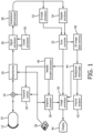
FIGURE 1 illustrates an ultrasound system configured in accordance with the principles of the present invention. -
FIGURE 2 illustrates the angles of incidence between a needle and unsteered beams from a curved array transducer. -
FIGURE 3 is an ultrasound image of insertion of a needle into a subject at the insertion angle shown inFIGURE 2 . -
FIGURE 4 illustrates acquisition of a needle image by steering beams in parallel at an optimal angle from a curved array transducer. -
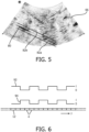
FIGURE 5 is an ultrasound image of a needle with its location indicated by a needle guide graphic. -
FIGURE 6 illustrates a first dual apodization technique, which is not within the scope of the claims, which can be used to reduce clutter arising due to beam steering in needle guidance imaging. -
FIGURES 7a and 7b illustrate a second dual apodization technique, which is not within the scope of the claims, which can be used to reduce clutter arising due to beam steering in needle guidance imaging. -
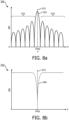
FIGURES 8a and 8b illustrate the sidelobe energy resulting from use of the two apodization functions ofFIGURES 7a and 7b . -
FIGURE 9 illustrates the reduction of sidelobe clutter achieved by a combination of the two apodization functions ofFIGURES 7a and 7b . -
FIGURE 10 is a flowchart of an ultrasound image guided needle insertion procedure conducted in accordance with the principles of the present invention. - In accordance with the principles of the present invention an ultrasound system and probe with a convex curved array transducer are used for needle insertion guidance. The natural curvature of the array causes its unsteered beams to traverse a wide sector angle which extends beyond the footprint of the probe and quickly captures a needle during initial insertion. Images of the needle are analyzed to determine a point where the angle of incidence between an ultrasound beam and the needle shaft are best for needle image acquisition, and a needle image is acquired with beams steered in parallel from the curved array at the optimized beam angle. The needle location is indicated in the image with a needle guide graphic. The optimized beam angle is periodically updated during the procedure. In accordance with an aspect of the present disclosure not within the scope of the claims, clutter arising due to steep beam steering angles is reduced by producing images of a scan field with two different apodization functions, which are then compared or combined to reduce image clutter.
- Referring now to
FIGURE 1 , an ultrasonic diagnostic imaging system constructed in accordance with the principles of the present invention is shown in block diagram form. A convexcurved transducer array 12 is provided in anultrasound probe 10 for transmitting ultrasonic waves and receiving echo information. The curved array transducer is coupled by the probe cable to a transmit/receive (T/R)switch 16 which switches between transmission and reception and protects themain beamformer 20 from high energy transmit signals. The transmission of ultrasonic beams from thecurved array 12 is done under control of atransmit controller 18 coupled to the T/R switch and thebeamformer 20, which receives input from the user's operation of the user interface orcontrol panel 38. Among the transmit characteristics controlled by the transmit controller are the amplitude, phase, and polarity of transmit waveforms, as well as the focusing and steering of ultrasound beams effected together with beamformer control. Beams formed in the direction of ultrasound transmission may be unsteered (directions orthogonal to the face of the transducer), or steered at different angles relative to the face of the array. The echoes received by a contiguous group of transducer elements referred to as the active aperture are beamformed in thebeamformer 20 by appropriately delaying them and then combining them to form a coherent echo signal. - The coherent echo signals undergo signal processing by a
signal processor 26, which includes filtering by a digital filter and noise reduction as by spatial or frequency compounding. The signal processor can also shift the frequency band to a lower or baseband frequency range. The digital filter of thesignal processor 26 can be a filter of the type disclosed inU.S. Patent No. 5,833,613 (Averkiou et al. ), for example. In accordance with one aspect of the present disclosure not within the scope of the claims, aclutter processor 50 is coupled to the signal processor to remove sidelobe clutter arising during beam steering as described more fully below. The processed echo signals are demodulated into quadrature (I and Q) components by aquadrature demodulator 28, which provides signal phase information. - The beamformed and processed coherent echo signals are coupled to a
B mode processor 52 which produces a B mode tissue image. The B mode processor performs amplitude (envelope) detection of quadrature demodulated I and Q signal components by calculating the echo signal amplitude in the form of (I2+Q2)½. The quadrature echo signal components are also coupled to aDoppler processor 54, which stores ensembles of echo signals from discrete points in an image field which are then used to estimate the Doppler shift at points in the image with a fast Fourier transform (FFT) processor. For a color Doppler image, the estimated Doppler flow values at each point in a blood vessel are wall filtered and converted to color values using a look-up table. The B mode image signals and the Doppler flow values are coupled to ascan converter 32 which converts the B mode and Doppler samples from their acquired R-θ coordinates to Cartesian (x,y) coordinates for display in a desired display format, e.g., a rectilinear display format or a sector display format as shown inFIGURES 3 and5 . Either the B mode image or the Doppler image may be displayed alone, or the two shown together in anatomical registration in which the color Doppler overlay shows the blood flow in tissue and vessel structure in the image. - The ultrasound image data produced by the
scan converter 32 are coupled to animage processor 30 and a 3D image data memory. Theimage processor 30 performs further enhancement, buffering and temporary storage for display of an ultrasound image on animage display 40. The 3D image data memory stores image data values at addresses related to their coordinates in 3D space, from which they can be accessed for 3D image formation. The 3D image data memory is coupled to amultiplanar reformatter 44 and avolume renderer 42. The multiplanar reformatter converts echoes which are received from points in a common plane in a volumetric region of the body into an ultrasonic image of that plane, as described inUS Pat. 6,443,896 (Detmer ). Thevolume renderer 42 converts the echo signals of a 3D data set into a projected 3D image as viewed from a given reference point as described inUS Pat. 6,530,885 (Entrekin et al. ) The 2D or 3D images produced from 3D image data are coupled to theimage processor 30. A graphic display overlay containing textual and other graphic information such as patient ID is produced by agraphics processor 36 for display with the ultrasound images. -
FIGURE 2 illustrates animage field 60 which is scanned byunsteered beams 62 transmitted and received by a curved array transducer. The beams are unsteered because their directions are determined by the curved geometry of the array; each beam is directed normal to its point of origin along the face of the array. In beam formation, unsteered beams are formed by equally weighting echoes received at symmetrical locations of the active aperture on either side of the point of origin. The beams have a symmetrical weighting profile in the beamformer. The same symmetrical weighting profile can be used to form each beam along the array, with the different angular directions of the beams provided by the geometrical array curvature. The natural curvature of the array thus causes eachbeam 62 to be directed at a different angle across the image field, thus scanning a sector-shapedfield 60. This is advantageous for needle insertion imaging, as only a single weighting table needs to be loaded into the beamformer for scanning and echo formation along each different beam direction. The broad sector image field is advantageous for needle insertion imaging, since the needle is inserted into the body at the side of the probe, and in line with the scan plane. The needle is quickly acquired at the edge of the wide image, as it will begin to intersect beams at the side of the sector after just a few millimeters of insertion. - But the angle of the inserted needle relative to the beam angles will cause different degrees of echo detection from different transmit beams depending on the angle of incidence of the beams impinging upon the needle. In the illustration the beams intersecting the
needle 70 before and after the centraldarkened section 72 are at non-orthogonal angles relative to the needle shaft. Echoes from these beams will scatter in directions away from the beam path, and less of their energy will return to the array elements. The darkened beams on either side ofbeam 64 are more orthogonal to the shaft ofneedle 70, causing more of their energy to be reflected back directly to the array. Thebeam 64 is most optimal as it is nearly orthogonal to the needle at its point of intersection and echoes from this beam will most strongly return to the array from the specular reflecting needle. Thus thesection 72 of the needle which produces these stronger echo returns will appear most distinctly in the ultrasound image, as clearly shown in theactual ultrasound image 66 ofFIGURE 3 . (This image is shown with black-white display reversal for better illustration.) - In accordance with the present invention, the ultrasound system includes a
needle location processor 46 which identifies thedistinct needle section 72 in theultrasound image 66, and particularly the angle of the mostoptimal beam 64. The needle location processor uses image processing to search for and identify the straight line of strong echoes fromneedle section 72 in the image. This can be done using image processing techniques such as Hough transforms, Radon transforms, first- and second-order directional texture analysis, or heuristic criteria such as maximum brightness analysis. When this echo return section is identified in the image, the point along the section of the strongest echo return denotes the point where the optimal unsteered beam intersects the needle, and the identity of the beam is thus determined by simple geometry. Withbeam 64 thereby identified as the unsteered beam with the optimal angle for imaging the needle most strongly, the needle location processor commands the transmitcontroller 18 andbeamformer 20 to transmit and receive steered beams from thearray 12, all steered at the identified optimal angle ofbeam 64. This is shown inFIGURE 4 , where thearray 12 is shown transmitting beams 64' ...64...64", all transmitted and received at the same angle relative to theneedle 70, an angle which is nearly orthogonal to the needle. Also shown for comparison arearrows 62 depicting unsteered beam angles from thearray 12. The steered beams 64' ...64...64" are seen to emanate from the same points along the face F of the array as the unsteered beams, but are steered by phased operation at different respective angles relative to the face F of the array which causes them to all be directed in parallel, and to impinge upon the needle at an orthogonal or nearly orthogonal angle. Imaging the needle with these parallel steered beams will produce relatively strong echo returns from theneedle 70, and a sharper, clearer appearance of the needle in the ultrasound image. - Scanning with parallel steered beams from a curved array is a nonobvious use of a curved array. This is because a curved array has an inherent preferential radial scan pattern due to its curved geometry. A standard flat linear array, by comparison, has no inherent radial scan pattern. Its flat geometry has made it the array of choice for linear as well as phased beam steering. So-called "steered linear" scanning has long been performed by phased operation of flat linear arrays for color Doppler imaging, as exemplified by
US Pat. 5,014,710 (Maslak et al. ), as has phased sector scanning. One skilled in ultrasonic imaging would choose a curved array specifically to take advantage of its natural radial scan pattern, not for use in steered parallel beam scanning. Not only is the curved array geometrically unsuited for this mode of operation; phased steering of beams from a curved array quickly gives rise to side lobe artifact clutter due to steep beam steering angles, as discussed in detail below. - When the
needle location processor 46 has operated as described to locate the needle in the ultrasound image as just explained, it further commands thegraphics processor 36 to overlay theultrasound image 66 with a needle location graphic as shown inFIGURE 5 . Needle guidance systems of the prior art have generally positioned needle location graphics over the location of the needle itself, as shown by the dotted graphic 80 which is positioned over the needle location in the body. This can pose a difficulty, as the image of the needle is obscured by the graphic. Often, the clinician would prefer to have the needle in the image unobstructed, particularly around the needle tip, which the clinician is usually focused on most intently to guide the insertion. A preferred graphic which does not obstruct the needle in the image hasgraphic lines graphics lines - As needle insertion progresses, the direction of insertion can change as the clinician manipulates the needle to avoid piercing blood vessels or work around hard substances in the body. Since the needle orientation can change due to needle manipulation or probe movement, the image processing and optimal beam angle identification and beam steering are repeated periodically by the
needle location processor 46, updating the steering angle ofbeams 64, 64' as needed to maintain the clearest image of the needle as can be afforded by the procedure. - An ultrasound array, like a radio antenna, exhibits an energy profile of the ultrasound energy transmitted or received by the array. This antenna pattern for an ultrasound array is known as a lobe pattern. The pattern has a main or central lobe which axially aligns with the beam direction, and side lobes which can also be sensitive to off-axis echo reception. In most instances, the clinician would prefer a strong, narrow main lobe in the beam direction, and virtually nonexistent side lobes. This is because energy received in side lobes in the image field can result in the production of artifacts in the image during beamformation, clutter which can obscure the image of the needle. The beamformer is programmed on the assumption that all energy is being received from along the beam axis. Off-axis energy received from the side lobes will be undesirably beamformed and manifest itself as artifacts in the resultant image. Side lobe clutter artifacts are prevented by using a probe with an element pitch (center-to-center spacing) which is less than half of the ultrasound frequency wavelength. When the beams of the curved array are unsteered, a half-wavelength element pitch will avoid the appearance of side lobe clutter. But when beams are steered at increasing nonorthogonal angles to the face of the array, side lobes become larger and the likelihood of side lobe artifacts increases, particularly in the case of a curved array where the array curvature causes the steered angles at the face of the array to be steeper than would be the case with a flat linear array. In
FIGURE 4 it is seen that the outermost needle imaging beams 64' and 64" are at significant nonorthogonal steering angles relative to the face F of thearray 12, and these steeper steering angles can be a source of side lobe image clutter. In accordance with an aspect of the present invention not within the scope of the claims, side lobe clutter is reduced by aclutter processor 50 in the ultrasound system. Theclutter processor 50 operates by forming two ultrasound images from the echoes produces from a scan of the image field, each using a different apodization function. The pixel values of the two differently apodized images are combined to reduce side lobe clutter artifacts in the final image. - One set of apodization functions for clutter removal is shown in
FIGURE 6 . At the bottom of the drawing is anarray 12 of transducer elements e, extending in a direction y. Shown above thearray 12 in spatial correspondence are two different apodization functions 92 and 92. One apodization function is used when beamforming the echo signals received from the image field to form a first image, and the other apodization function is used when beamforming the same echo signals to form a second image. It is seen thatapodization function 92 weights the signals from two adjacent elements with a weight of one, then the signals from the next two elements with a weight of zero, then the next two signals with a weight of one, and so on. Theapodization function 94 is the inverse, with the same alternation of one and zero weights across the aperture. The beamformed echo signals of the two images are amplitude detected, producing pixel values for the two images. Pixel values at the same spatial location in the two images are then compared or correlated. If the correlation of the two values is high, such as greater than 50%, one or both of the values are used for that pixel value in the resultant image. If the correlation of the two values is relatively low, such as less than 50%, the values are omitted from the image. That is because the main lobe signals processed by the two complementary apodization functions will be approximately the same, whereas signals from the side lobes on either side of the main lobe in the two images, the side lobes which are the greatest contributors of clutter, will be of opposite polarity and de-correlated. Thus, side lobe clutter is reduced in the resultant image. Since this processing is all done on a single image acquisition, there is no adverse effect on the frame rate of display. And since this clutter reduction processing uses amplitude detection, the resultant pixel values can be directly processed into a B mode image by theB mode processor 52. - Preferred apodization functions for clutter reduction of needle images are shown in
FIGURES 7a and 7b . The graphs of these two drawings are plotted as voltage weighting, v, against distance from the center of the ultrasonic transducer array, y. Thegraph 410 ofFIGURE 7a shows an example of a first apodization function in the form of a rectangular apodization function. This apodization function results in signals from all of the elements of the transducer array receive an equal weighting such as one. The results of applying this function to the received echo data are shown inFIGURE 8a . -
FIGURE 8a shows aplot 500 of magnitude, measured in dB, against steering angle θ. The plot depicts the summation of all of the echo signals received by each transducer element of a transducer array, across all of the steering angles within the field of view of the array. More specifically, the plot shows the main and side lobe response in image data beamformed using thefirst apodization function 410 shown inFIGURE 7a . This is the response characteristic of a standard unapodized B-mode ultrasound image, which has a high intensity response at a steering angle of 0° 510, themain lobe response 520. Signals from a steering angle of 0° arrive coherently at the transducer array and form the main lobe response of an image usinguniform apodization function 410. Due to spatial resolution limitations, themain lobe 520 has a finite width that includes a small range of angles either side of zero degrees. Image data with this characteristic also includes multiple signals of diminishing intensity spreading out from the main lobe, theside lobes 530. The side lobes are the response of signals with a steering angle outside of the range of the main lobe. Constructive and destructive interference effects at different angles create the peaks and troughs in the side lobes. The side lobes contribute the clutter in an ultrasound image, whereas the main lobe provides the desired signals from the ultrasound image target. - The
second graph 420 ofFIGURE 7b shows an example of a second apodization function in the form of a reciprocal function, such as y = 1/x, which is used to introduce a null point in the image data response as illustrated byFIGURE 8b . When this notch filter is applied as a pass filter to the lobe characteristic 500, signals from the main lobe of the beampattern of the array receive a high weighting, which decreases exponentially towards signals from the more lateral side lobes. The results of applying this function to the received echo data are shown inFIGURE 9 . The shapes of the apodization functions used may be designed by the user of the ultrasound system or may be preloaded onto the system and selected by the user to perform a desired function. Once the shape of an apodization function has been selected or designed, it may be adjusted through a single control parameter. This parameter is a scaling factor, k, which may be empirically determined by the user through the use of the ultrasound system. - Linear acoustics dictates that the ultrasound beampattern is equivalent to the Fourier transform of the apodization function used. This relationship provides a tool for analysis and beampattern design. More specifically, it is possible to design the apodization function to achieve a desired beampattern. For example, the image data produced by use of the
apodization function 420 will exhibit a sharp null at the main lobe location and a decreased amplitude at off-axis steering angles, as shown inFIGURE 8b . The Fourier transform relationship between theapodization function 420 and the beampattern of the second image data can be used to discern what type of apodization function should be used to achieve the desired beampattern. - By applying the reciprocal
second apodization function 420 to the echo signal data, a null 560 is generated at the same steering angle as themain lobe 520 of the image data processed usingapodization function 410. In this example, thesecond apodization function 420 is acting as a notch filter; however, depending on the application, many different shapes of apodization function may be utilized. -
FIGURE 9 shows aplot 600 depicting a superposition of the plots fromFIGURES 8a and 8b , which depict the image data resulting from use of the first and second apodization functions 410 and 420, respectively, for an image pixel. By comparing pixels of the first and second images processed by the apodization functions, the minimum signal magnitude across the steering angles can be found. This is highlighted by dashedlines 630 of the side lobe response. Signals of the desiredmain lobe 610 fall in the notch of the characteristic of thesecond apodization function 620. In this way, the clutter signals of theside lobes 630 are selected and isolated from the signals of themain lobe 610. The unwanted values from theside lobe response 630 are then subtracted from the image data obtained using thefirst apodization function 410 with the response shown inFIGURE 8a . The result is signals mainly returned from themain lobe response 520, and the signals of theside lobes 530 of the lobe pattern have been substantially eliminated, meaning that the resulting signal used for imaging is primarily signals from the main lobe response of the lobe characteristic. In this way, sidelobe clutter is substantially removed from the ultrasound image. - The shape of the second apodization function, shown in
graph 420 ofFIGURE 7b , may be altered to change the width of thenull function 560 in the second image data. In this way, the angular spread of the remaining signals may be controlled. By reducing the width of this notch function, the spatial resolution of the final ultrasound image may be increased. - An ultrasound image-guided needle insertion procedure in accordance with the present invention is outlined in
FIGURE 10 . A clinician begins the procedure by positioning a curved array transducer probe on the body of a subject, manipulating the probe until the target anatomy for the procedure is in the field of view. The target anatomy may be a cyst which is to be biopsied using a needle, for instance. With the target anatomy in view in the ultrasound image, the clinician starts inserting the needle in-line with the plane of the image, as stated instep 102. As the insertion proceeds, the curved array transducer transmits unsteered beams over the field of view to image the field and capture the insertion of the needle as stated instep 104. Instep 106 the needle location processor of the ultrasound system identifies the line of specular needle reflections in the image, where the radially directed beams from the curved array are intersecting the needle around the most favorable angle. Instep 108 the needle location processor identifies the brightest point along the needle reflection line, which identifies the angle of the transmit beam which produced that bright point as stated instep 110. The needle location processor then causes the transmit controller to control the curved array transducer to transmit parallel steered beams toward the needle at the identified beam angle as stated instep 112. Scanning with the parallel steered beams produces the strongest image of the needle, and a needle guide graphic is displayed with the image instep 114, preferably on either side of the location of the needle in the ultrasound image. Clutter reduction may then be performed using one of the dual apodization processing techniques explained above. - It should be noted that an ultrasound system suitable for use in an implementation of the present invention, and in particular the component structure of the ultrasound system of
FIGURE 1 , may be implemented in hardware, software or a combination thereof. The various embodiments and/or components of an ultrasound system, for example, theneedle location processor 46 and theclutter processor 50, or components and controllers therein, also may be implemented as part of one or more computers or microprocessors. The computer or processor may include a computing device, an input device, a display unit and an interface, for example, for accessing the Internet. The computer or processor may include a microprocessor. The microprocessor may be connected to a communication bus, for example, to access a PACS system or the data network for importing images. The computer or processor may also include a memory. The memory devices such as the 3Dimage data memory 48 may include Random Access Memory (RAM) and Read Only Memory (ROM). The computer or processor further may include a storage device, which may be a hard disk drive or a removable storage drive such as a floppy disk drive, optical disk drive, solid-state thumb drive, and the like. The storage device may also be other similar means for loading computer programs or other instructions into the computer or processor. - As used herein, the term "computer" or "module" or "processor" or "workstation" may include any processor-based or microprocessor-based system including systems using microcontrollers, reduced instruction set computers (RISC), ASICs, logic circuits, and any other circuit or processor capable of executing the functions described herein. The above examples are exemplary only, and are thus not intended to limit in any way the definition and/or meaning of these terms.
- The computer or processor executes a set of instructions that are stored in one or more storage elements, in order to process input data. The storage elements may also store data or other information as desired or needed. The storage element may be in the form of an information source or a physical memory element within a processing machine.
- The set of instructions of an ultrasound system including those controlling the acquisition, processing, and transmission of ultrasound images as described above may include various commands that instruct a computer or processor as a processing machine to perform specific operations such as the methods and processes of the various embodiments of the invention. The set of instructions may be in the form of a software program. The software may be in various forms such as system software or application software and which may be embodied as a tangible and non-transitory computer readable medium. Further, the software may be in the form of a collection of separate programs or modules such as a needle location module, a clutter module, a program module within a larger program or a portion of a program module. The software also may include modular programming in the form of object-oriented programming. The processing of input data by the processing machine may be in response to operator commands, or in response to results of previous processing, or in response to a request made by another processing machine.
Claims (13)
- A method for operating an ultrasonic imaging system for image guidance of needle insertion in a subject, the method comprising:transmitting (104) unsteered beams from a curved array transducer in the probe over an image field in the subject, and thereby obtaining an ultrasound image of said image field using the unsteered beams;identifying (110) a peak angle of a transmit beam for producing a peak magnitude of echo returns from a needle in the image field based on application of image processing to search for and identify a straight line of strong specular reflections from a section of the needle in said ultrasound image;transmitting (112) a plurality of parallel steered beams at the peak angle; anddisplaying (114) a further ultrasound image of the needle in the image field, the further ultrasound image obtained based on the steered beams.
- The method of Claim 1, comprising identifying (108) a brightest point along the line of needle specular reflections.
- The method of Claim 2, wherein identifying (110) the angle of the transmit beam comprises identifying the transmit beam which intersects the line of needle specular reflections at the brightest point,
wherein the identified transmit beam further exhibits the peak angle. - The method of Claim 1, wherein displaying (114) the further ultrasound image of the needle comprises displaying a needle guide graphic in the image.
- The method of Claim 4, wherein displaying the needle guide graphic comprises displaying a graphic line (80) at a location of the needle in the further ultrasound image.
- The method of Claim 4, wherein displaying the needle guide graphic comprises displaying needle guide graphic lines (82a, 82b) on either side of a location of the needle in the further ultrasound image.
- The method of Claim 4, wherein displaying the needle guide graphic comprises displaying graphic lines (80, 82a, 82b) at the location of the needle in the ultrasound image and on either side of a location of the needle in the further ultrasound image.
- An ultrasonic imaging system for image guidance of needle insertion in a subject, the system comprising:an ultrasound probe (10) comprising a curved array transducer (12);a transmit controller (18) configured to control the curved array transducer to transmit unsteered beams (62) over an image field (60) in the subject, wherein the system is configured to obtain an ultrasound image of said image field using the unsteered beams; anda needle location processor (46) configured to identify a peak angle of a transmit beam (64) for producing a peak magnitude of echo returns from a needle (70) in the image field based on application of image processing to search for and identify a straight line of strong specular reflections from a section of the needle in said ultrasound image;wherein the transmit controller (18) is further configured to control the curved array transducer (12) to transmit a plurality of parallel steered beams (64') at the peak angle, andwherein the system further comprises an image display (40) configured to display a further ultrasound image of the needle (70) in the image field, the further ultrasound image being obtained based on the steered beams (64').
- The system of Claim 8, wherein the needle location processor (46) is further configured to identify a brightest point along the line of needle specular reflections.
- The system of Claim 9, wherein the needle location processor (46) is further configured to identify the angle of the transmit beam by identifying the transmit beam which intersects the line of needle specular reflections at the brightest point, wherein the identified transmit beam further exhibits the peak angle.
- The system of Claim 8, wherein the image display (40)is further configured to display a needle guide graphic in the further ultrasound image.
- The system of Claim 11, wherein the needle guide graphic comprises a graphic line (80) at a location of the needle (70) in the further ultrasound image and/or guide graphic lines (82a, 82b) on either side of a location of the needle (70) in the further ultrasound image.
- A computer program comprising a set of instructions which, when the program is executed in a processor of the ultrasonic imaging system of any of Claims 8-12, cause the processor a to carry out the steps of the method of any of Claims 1-7.
Applications Claiming Priority (2)
| Application Number | Priority Date | Filing Date | Title |
|---|---|---|---|
| US201862620512P | 2018-01-23 | 2018-01-23 | |
| PCT/EP2019/050844 WO2019145183A1 (en) | 2018-01-23 | 2019-01-15 | Ultrasound imaging system providing needle insertion guidance |
Publications (2)
| Publication Number | Publication Date |
|---|---|
| EP3742981A1 EP3742981A1 (en) | 2020-12-02 |
| EP3742981B1 true EP3742981B1 (en) | 2024-03-13 |
Family
ID=65036779
Family Applications (1)
| Application Number | Title | Priority Date | Filing Date |
|---|---|---|---|
| EP19700888.1A Active EP3742981B1 (en) | 2018-01-23 | 2019-01-15 | Ultrasound imaging system providing needle insertion guidance |
Country Status (5)
| Country | Link |
|---|---|
| US (2) | US11918300B2 (en) |
| EP (1) | EP3742981B1 (en) |
| JP (3) | JP7401459B2 (en) |
| CN (1) | CN111629672B (en) |
| WO (1) | WO2019145183A1 (en) |
Family Cites Families (30)
| Publication number | Priority date | Publication date | Assignee | Title |
|---|---|---|---|---|
| US5014710A (en) | 1988-09-13 | 1991-05-14 | Acuson Corporation | Steered linear color doppler imaging |
| US5105814A (en) * | 1990-08-15 | 1992-04-21 | Hewlett-Packard Company | Method of transforming a multi-beam ultrasonic image |
| US5235982A (en) * | 1991-09-30 | 1993-08-17 | General Electric Company | Dynamic transmit focusing of a steered ultrasonic beam |
| US5833613A (en) | 1996-09-27 | 1998-11-10 | Advanced Technology Laboratories, Inc. | Ultrasonic diagnostic imaging with contrast agents |
| US6193659B1 (en) * | 1997-07-15 | 2001-02-27 | Acuson Corporation | Medical ultrasonic diagnostic imaging method and apparatus |
| US20020173721A1 (en) * | 1999-08-20 | 2002-11-21 | Novasonics, Inc. | User interface for handheld imaging devices |
| US6530885B1 (en) | 2000-03-17 | 2003-03-11 | Atl Ultrasound, Inc. | Spatially compounded three dimensional ultrasonic images |
| US6443896B1 (en) | 2000-08-17 | 2002-09-03 | Koninklijke Philips Electronics N.V. | Method for creating multiplanar ultrasonic images of a three dimensional object |
| US6524247B2 (en) | 2001-05-15 | 2003-02-25 | U-Systems, Inc. | Method and system for ultrasound imaging of a biopsy needle |
| US6951542B2 (en) | 2002-06-26 | 2005-10-04 | Esaote S.P.A. | Method and apparatus for ultrasound imaging of a biopsy needle or the like during an ultrasound imaging examination |
| JP2003126093A (en) * | 2001-10-23 | 2003-05-07 | Olympus Optical Co Ltd | Ultrasonic diagnostic apparatus |
| JP2004208859A (en) | 2002-12-27 | 2004-07-29 | Toshiba Corp | Ultrasonic diagnostic equipment |
| CN100539951C (en) * | 2004-11-17 | 2009-09-16 | 株式会社日立医药 | Diagnostic ultrasound equipment |
| US8254654B2 (en) | 2007-10-31 | 2012-08-28 | University Of Southern California | Sidelobe suppression in ultrasound imaging using dual apodization with cross-correlation |
| WO2011057252A1 (en) | 2009-11-09 | 2011-05-12 | Sonosite, Inc. | Systems and methods for beam enhancement |
| WO2012049124A2 (en) | 2010-10-11 | 2012-04-19 | B-K Medical Aps | Methods and systems for producing compounded ultrasound images |
| RU2627596C2 (en) * | 2010-11-19 | 2017-08-09 | Конинклейке Филипс Электроникс Н.В. | Method of controlling the introduction of surgical instrument through three-dimensional ultrasound visualization |
| JP5435751B2 (en) | 2011-03-03 | 2014-03-05 | 富士フイルム株式会社 | Ultrasonic diagnostic apparatus, ultrasonic transmission / reception method, and ultrasonic transmission / reception program |
| JP5891098B2 (en) | 2012-04-23 | 2016-03-22 | 富士フイルム株式会社 | Ultrasonic diagnostic apparatus and method for operating ultrasonic diagnostic apparatus |
| JP6257997B2 (en) * | 2012-10-23 | 2018-01-10 | 東芝メディカルシステムズ株式会社 | Ultrasonic diagnostic apparatus and ultrasonic diagnostic apparatus control method |
| CN103845075B (en) * | 2012-11-30 | 2016-09-28 | 通用电气公司 | Vltrasonic device and ultrasonic imaging method |
| US9642592B2 (en) * | 2013-01-03 | 2017-05-09 | Siemens Medical Solutions Usa, Inc. | Needle enhancement in diagnostic ultrasound imaging |
| EP3126872B1 (en) * | 2014-03-31 | 2021-05-12 | Koninklijke Philips N.V. | System and method for acoustic imaging with coherent compounding using intercostal spaces |
| JP6309340B2 (en) | 2014-05-08 | 2018-04-11 | キヤノンメディカルシステムズ株式会社 | Ultrasonic diagnostic apparatus and ultrasonic imaging program |
| US10624612B2 (en) * | 2014-06-05 | 2020-04-21 | Chikayoshi Sumi | Beamforming method, measurement and imaging instruments, and communication instruments |
| US11020143B2 (en) * | 2015-07-20 | 2021-06-01 | Edan Instruments, Inc. | Adaptive steering adjustment for needle visualization |
| US10292678B2 (en) * | 2015-09-23 | 2019-05-21 | Analogic Corporation | Real-time image based risk assessment for an instrument along a path to a target in an object |
| US10281568B2 (en) * | 2015-10-16 | 2019-05-07 | The Board Of Trustees Of The University Of Illinois | Method and apparatus for null subtraction ultrasound imaging |
| KR20170060852A (en) * | 2015-11-25 | 2017-06-02 | 삼성메디슨 주식회사 | Method and ultrasound apparatus for providing ultrasound images |
| JP6668817B2 (en) * | 2016-02-26 | 2020-03-18 | コニカミノルタ株式会社 | Ultrasound diagnostic apparatus and control program |
-
2019
- 2019-01-15 EP EP19700888.1A patent/EP3742981B1/en active Active
- 2019-01-15 US US16/963,859 patent/US11918300B2/en active Active
- 2019-01-15 CN CN201980009884.8A patent/CN111629672B/en active Active
- 2019-01-15 WO PCT/EP2019/050844 patent/WO2019145183A1/en unknown
- 2019-01-15 JP JP2020560552A patent/JP7401459B2/en active Active
-
2023
- 2023-05-19 JP JP2023083092A patent/JP7550919B2/en active Active
- 2023-12-07 JP JP2023206609A patent/JP2024026301A/en active Pending
-
2024
- 2024-01-30 US US18/426,712 patent/US20240164847A1/en active Pending
Also Published As
| Publication number | Publication date |
|---|---|
| JP7550919B2 (en) | 2024-09-13 |
| WO2019145183A1 (en) | 2019-08-01 |
| JP2021510618A (en) | 2021-04-30 |
| CN111629672B (en) | 2024-08-23 |
| EP3742981A1 (en) | 2020-12-02 |
| US20210038320A1 (en) | 2021-02-11 |
| JP2023106510A (en) | 2023-08-01 |
| US11918300B2 (en) | 2024-03-05 |
| US20240164847A1 (en) | 2024-05-23 |
| JP2024026301A (en) | 2024-02-28 |
| CN111629672A (en) | 2020-09-04 |
| JP7401459B2 (en) | 2023-12-19 |
Similar Documents
| Publication | Publication Date | Title |
|---|---|---|
| US9597054B2 (en) | Ultrasonic guidance of a needle path during biopsy | |
| US9451932B2 (en) | Clutter suppression in ultrasonic imaging systems | |
| EP1292847B1 (en) | Ultrasonic spatial compounding with curved array scanheads | |
| KR102396008B1 (en) | Ultrasound imaging system and method for tracking a specular reflector | |
| US9204862B2 (en) | Method and apparatus for performing ultrasound elevation compounding | |
| EP2820445A2 (en) | Clutter suppression in ultrasonic imaging systems | |
| EP3512432B1 (en) | An apparatus and method for detecting an interventional tool | |
| JP7449278B2 (en) | 3D ultrasound imaging with wide focused transmit beam at high display frame rate | |
| US11408987B2 (en) | Ultrasonic imaging with multi-scale processing for grating lobe suppression | |
| CN107997783B (en) | Self-adaptive ultrasonic beam synthesis method and system based on ultrasonic directionality | |
| US8394027B2 (en) | Multi-plane/multi-slice processing for 2-D flow imaging in medical diagnostic ultrasound | |
| US11523798B2 (en) | Ultrasound imaging system and method for detecting position and orientation of a coherent reflector | |
| US20180038947A1 (en) | Clutter suppression in ultrasonic imaging systems | |
| JP7065894B2 (en) | Methods and systems for processing ultrasound images | |
| CN110636799A (en) | Optimal scan plane selection for organ viewing | |
| EP3742981B1 (en) | Ultrasound imaging system providing needle insertion guidance | |
| US20210338209A1 (en) | High quality high frame rate ultrasound imaging with diverging transmit beams | |
| US11607194B2 (en) | Ultrasound imaging system with depth-dependent transmit focus | |
| WO2018050885A1 (en) | An apparatus and method for detecting an interventional tool |
Legal Events
| Date | Code | Title | Description |
|---|---|---|---|
| STAA | Information on the status of an ep patent application or granted ep patent |
Free format text: STATUS: UNKNOWN |
|
| STAA | Information on the status of an ep patent application or granted ep patent |
Free format text: STATUS: THE INTERNATIONAL PUBLICATION HAS BEEN MADE |
|
| PUAI | Public reference made under article 153(3) epc to a published international application that has entered the european phase |
Free format text: ORIGINAL CODE: 0009012 |
|
| STAA | Information on the status of an ep patent application or granted ep patent |
Free format text: STATUS: REQUEST FOR EXAMINATION WAS MADE |
|
| 17P | Request for examination filed |
Effective date: 20200824 |
|
| AK | Designated contracting states |
Kind code of ref document: A1 Designated state(s): AL AT BE BG CH CY CZ DE DK EE ES FI FR GB GR HR HU IE IS IT LI LT LU LV MC MK MT NL NO PL PT RO RS SE SI SK SM TR |
|
| AX | Request for extension of the european patent |
Extension state: BA ME |
|
| DAV | Request for validation of the european patent (deleted) | ||
| DAX | Request for extension of the european patent (deleted) | ||
| STAA | Information on the status of an ep patent application or granted ep patent |
Free format text: STATUS: EXAMINATION IS IN PROGRESS |
|
| 17Q | First examination report despatched |
Effective date: 20220608 |
|
| GRAP | Despatch of communication of intention to grant a patent |
Free format text: ORIGINAL CODE: EPIDOSNIGR1 |
|
| STAA | Information on the status of an ep patent application or granted ep patent |
Free format text: STATUS: GRANT OF PATENT IS INTENDED |
|
| INTG | Intention to grant announced |
Effective date: 20230907 |
|
| GRAS | Grant fee paid |
Free format text: ORIGINAL CODE: EPIDOSNIGR3 |
|
| GRAA | (expected) grant |
Free format text: ORIGINAL CODE: 0009210 |
|
| STAA | Information on the status of an ep patent application or granted ep patent |
Free format text: STATUS: THE PATENT HAS BEEN GRANTED |
|
| AK | Designated contracting states |
Kind code of ref document: B1 Designated state(s): AL AT BE BG CH CY CZ DE DK EE ES FI FR GB GR HR HU IE IS IT LI LT LU LV MC MK MT NL NO PL PT RO RS SE SI SK SM TR |
|
| REG | Reference to a national code |
Ref country code: GB Ref legal event code: FG4D |
|
| REG | Reference to a national code |
Ref country code: CH Ref legal event code: EP |
|
| REG | Reference to a national code |
Ref country code: DE Ref legal event code: R084 Ref document number: 602019048159 Country of ref document: DE |
|
| REG | Reference to a national code |
Ref country code: DE Ref legal event code: R096 Ref document number: 602019048159 Country of ref document: DE |
|
| REG | Reference to a national code |
Ref country code: IE Ref legal event code: FG4D |
|
| PG25 | Lapsed in a contracting state [announced via postgrant information from national office to epo] |
Ref country code: LT Free format text: LAPSE BECAUSE OF FAILURE TO SUBMIT A TRANSLATION OF THE DESCRIPTION OR TO PAY THE FEE WITHIN THE PRESCRIBED TIME-LIMIT Effective date: 20240313 |
|
| REG | Reference to a national code |
Ref country code: LT Ref legal event code: MG9D |
|
| PG25 | Lapsed in a contracting state [announced via postgrant information from national office to epo] |
Ref country code: GR Free format text: LAPSE BECAUSE OF FAILURE TO SUBMIT A TRANSLATION OF THE DESCRIPTION OR TO PAY THE FEE WITHIN THE PRESCRIBED TIME-LIMIT Effective date: 20240614 |
|
| REG | Reference to a national code |
Ref country code: NL Ref legal event code: MP Effective date: 20240313 Ref country code: GB Ref legal event code: 746 Effective date: 20240626 |
|
| PG25 | Lapsed in a contracting state [announced via postgrant information from national office to epo] |
Ref country code: RS Free format text: LAPSE BECAUSE OF FAILURE TO SUBMIT A TRANSLATION OF THE DESCRIPTION OR TO PAY THE FEE WITHIN THE PRESCRIBED TIME-LIMIT Effective date: 20240613 Ref country code: HR Free format text: LAPSE BECAUSE OF FAILURE TO SUBMIT A TRANSLATION OF THE DESCRIPTION OR TO PAY THE FEE WITHIN THE PRESCRIBED TIME-LIMIT Effective date: 20240313 |
|
| PG25 | Lapsed in a contracting state [announced via postgrant information from national office to epo] |
Ref country code: ES Free format text: LAPSE BECAUSE OF FAILURE TO SUBMIT A TRANSLATION OF THE DESCRIPTION OR TO PAY THE FEE WITHIN THE PRESCRIBED TIME-LIMIT Effective date: 20240313 |
|
| PG25 | Lapsed in a contracting state [announced via postgrant information from national office to epo] |
Ref country code: RS Free format text: LAPSE BECAUSE OF FAILURE TO SUBMIT A TRANSLATION OF THE DESCRIPTION OR TO PAY THE FEE WITHIN THE PRESCRIBED TIME-LIMIT Effective date: 20240613 Ref country code: NO Free format text: LAPSE BECAUSE OF FAILURE TO SUBMIT A TRANSLATION OF THE DESCRIPTION OR TO PAY THE FEE WITHIN THE PRESCRIBED TIME-LIMIT Effective date: 20240613 Ref country code: LT Free format text: LAPSE BECAUSE OF FAILURE TO SUBMIT A TRANSLATION OF THE DESCRIPTION OR TO PAY THE FEE WITHIN THE PRESCRIBED TIME-LIMIT Effective date: 20240313 Ref country code: HR Free format text: LAPSE BECAUSE OF FAILURE TO SUBMIT A TRANSLATION OF THE DESCRIPTION OR TO PAY THE FEE WITHIN THE PRESCRIBED TIME-LIMIT Effective date: 20240313 Ref country code: GR Free format text: LAPSE BECAUSE OF FAILURE TO SUBMIT A TRANSLATION OF THE DESCRIPTION OR TO PAY THE FEE WITHIN THE PRESCRIBED TIME-LIMIT Effective date: 20240614 Ref country code: FI Free format text: LAPSE BECAUSE OF FAILURE TO SUBMIT A TRANSLATION OF THE DESCRIPTION OR TO PAY THE FEE WITHIN THE PRESCRIBED TIME-LIMIT Effective date: 20240313 Ref country code: ES Free format text: LAPSE BECAUSE OF FAILURE TO SUBMIT A TRANSLATION OF THE DESCRIPTION OR TO PAY THE FEE WITHIN THE PRESCRIBED TIME-LIMIT Effective date: 20240313 Ref country code: BG Free format text: LAPSE BECAUSE OF FAILURE TO SUBMIT A TRANSLATION OF THE DESCRIPTION OR TO PAY THE FEE WITHIN THE PRESCRIBED TIME-LIMIT Effective date: 20240313 |
|
| REG | Reference to a national code |
Ref country code: AT Ref legal event code: MK05 Ref document number: 1664973 Country of ref document: AT Kind code of ref document: T Effective date: 20240313 |
|
| PG25 | Lapsed in a contracting state [announced via postgrant information from national office to epo] |
Ref country code: SE Free format text: LAPSE BECAUSE OF FAILURE TO SUBMIT A TRANSLATION OF THE DESCRIPTION OR TO PAY THE FEE WITHIN THE PRESCRIBED TIME-LIMIT Effective date: 20240313 Ref country code: LV Free format text: LAPSE BECAUSE OF FAILURE TO SUBMIT A TRANSLATION OF THE DESCRIPTION OR TO PAY THE FEE WITHIN THE PRESCRIBED TIME-LIMIT Effective date: 20240313 |
|
| PG25 | Lapsed in a contracting state [announced via postgrant information from national office to epo] |
Ref country code: NL Free format text: LAPSE BECAUSE OF FAILURE TO SUBMIT A TRANSLATION OF THE DESCRIPTION OR TO PAY THE FEE WITHIN THE PRESCRIBED TIME-LIMIT Effective date: 20240313 |