EP3742831A1 - Verfahren und vorrichtung zur vermeidung von paging-kollisionen in einem drahtlosen kommunikationssystem - Google Patents
Verfahren und vorrichtung zur vermeidung von paging-kollisionen in einem drahtlosen kommunikationssystem Download PDFInfo
- Publication number
- EP3742831A1 EP3742831A1 EP20170292.5A EP20170292A EP3742831A1 EP 3742831 A1 EP3742831 A1 EP 3742831A1 EP 20170292 A EP20170292 A EP 20170292A EP 3742831 A1 EP3742831 A1 EP 3742831A1
- Authority
- EP
- European Patent Office
- Prior art keywords
- usim
- paging
- serving cell
- paging monitoring
- timing
- Prior art date
- Legal status (The legal status is an assumption and is not a legal conclusion. Google has not performed a legal analysis and makes no representation as to the accuracy of the status listed.)
- Pending
Links
Images


Classifications
-
- H—ELECTRICITY
- H04—ELECTRIC COMMUNICATION TECHNIQUE
- H04W—WIRELESS COMMUNICATION NETWORKS
- H04W68/00—User notification, e.g. alerting and paging, for incoming communication, change of service or the like
- H04W68/02—Arrangements for increasing efficiency of notification or paging channel
-
- H—ELECTRICITY
- H04—ELECTRIC COMMUNICATION TECHNIQUE
- H04W—WIRELESS COMMUNICATION NETWORKS
- H04W48/00—Access restriction; Network selection; Access point selection
- H04W48/18—Selecting a network or a communication service
-
- H—ELECTRICITY
- H04—ELECTRIC COMMUNICATION TECHNIQUE
- H04W—WIRELESS COMMUNICATION NETWORKS
- H04W68/00—User notification, e.g. alerting and paging, for incoming communication, change of service or the like
- H04W68/005—Transmission of information for alerting of incoming communication
-
- H—ELECTRICITY
- H04—ELECTRIC COMMUNICATION TECHNIQUE
- H04W—WIRELESS COMMUNICATION NETWORKS
- H04W76/00—Connection management
- H04W76/20—Manipulation of established connections
- H04W76/27—Transitions between radio resource control [RRC] states
-
- H—ELECTRICITY
- H04—ELECTRIC COMMUNICATION TECHNIQUE
- H04W—WIRELESS COMMUNICATION NETWORKS
- H04W8/00—Network data management
- H04W8/18—Processing of user or subscriber data, e.g. subscribed services, user preferences or user profiles; Transfer of user or subscriber data
- H04W8/183—Processing at user equipment or user record carrier
-
- H—ELECTRICITY
- H04—ELECTRIC COMMUNICATION TECHNIQUE
- H04W—WIRELESS COMMUNICATION NETWORKS
- H04W88/00—Devices specially adapted for wireless communication networks, e.g. terminals, base stations or access point devices
- H04W88/02—Terminal devices
- H04W88/06—Terminal devices adapted for operation in multiple networks or having at least two operational modes, e.g. multi-mode terminals
-
- H—ELECTRICITY
- H04—ELECTRIC COMMUNICATION TECHNIQUE
- H04W—WIRELESS COMMUNICATION NETWORKS
- H04W68/00—User notification, e.g. alerting and paging, for incoming communication, change of service or the like
- H04W68/12—Inter-network notification
Definitions
- This disclosure generally relates to wireless communication networks, and more particularly, to a method and apparatus for avoiding paging collision in a wireless communication system.
- IP Internet Protocol
- An exemplary network structure is an Evolved Universal Terrestrial Radio Access Network (E-UTRAN).
- E-UTRAN Evolved Universal Terrestrial Radio Access Network
- the E-UTRAN system can provide high data throughput in order to realize the above-noted voice over IP and multimedia services.
- a new radio technology for the next generation e.g., 5G
- 5G next generation
- changes to the current body of 3GPP standard are currently being submitted and considered to evolve and finalize the 3GPP standard.
- a method and device are disclosed from the perspective of a User Equipment (UE) with a first USIM (Universal Subscriber Identity Module) and a second USIM and are defined in the independent claims.
- the dependent claims define preferred embodiments thereof.
- the method includes the UE performing paging monitoring in a first serving cell associated with the first USIM.
- the method also includes the UE performing paging monitoring in a second serving cell associated with the second USIM.
- the method further includes the UE transmitting, to a network node associated with the second USIM, information related to at least one of the paging monitoring performed in the first serving cell or the paging monitoring performed in the second serving cell.
- Wireless communication systems are widely deployed to provide various types of communication such as voice, data, and so on. These systems may be based on code division multiple access (CDMA), time division multiple access (TDMA), orthogonal frequency division multiple access (OFDMA), 3GPP LTE (Long Term Evolution) wireless access, 3GPP LTE-A or LTE-Advanced (Long Term Evolution Advanced), 3GPP2 UMB (Ultra Mobile Broadband), WiMax, 3GPP NR (New Radio), or some other modulation techniques.
- CDMA code division multiple access
- TDMA time division multiple access
- OFDMA orthogonal frequency division multiple access
- 3GPP LTE Long Term Evolution
- 3GPP LTE-A or LTE-Advanced Long Term Evolution Advanced
- 3GPP2 UMB User Mobile Broadband
- WiMax Wireless Broadband
- 3GPP NR New Radio
- the exemplary wireless communication systems devices described below may be designed to support one or more standards such as the standard offered by a consortium named “3rd Generation Partnership Project” referred to herein as 3GPP, including: SP-190248, "Revised SID: Study on system enablers for multi-SIM devices "; TS 38.304 V15.3.0, "User Equipment (UE) procedures in Idle mode and RRC Inactive state “; TS 38.300 V15.5.0, “NR and NG-RAN Overall Description "; TS 38.331 V15.5.1, “NR Radio Resource Control (RRC) protocol specification "; and TS 24.501 V16.0.2, “Non-Access-Stratum (NAS) protocol for 5G System (5GS) ".
- 3GPP 3rd Generation Partnership Project
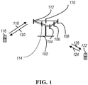
- FIG. 1 shows a multiple access wireless communication system according to one embodiment of the invention.
- An access network 100 includes multiple antenna groups, one including 104 and 106, another including 108 and 110, and an additional including 112 and 114. In FIG. 1 , only two antennas are shown for each antenna group, however, more or fewer antennas may be utilized for each antenna group.
- Access terminal 116 is in communication with antennas 112 and 114, where antennas 112 and 114 transmit information to access terminal 116 over forward link 120 and receive information from access terminal 116 over reverse link 118.
- Access terminal (AT) 122 is in communication with antennas 106 and 108, where antennas 106 and 108 transmit information to access terminal (AT) 122 over forward link 126 and receive information from access terminal (AT) 122 over reverse link 124.
- communication links 118, 120, 124 and 126 may use different frequency for communication.
- forward link 120 may use a different frequency then that used by reverse link 118.
- antenna groups each are designed to communicate to access terminals in a sector of the areas covered by access network 100.
- the transmitting antennas of access network 100 may utilize beamforming in order to improve the signal-to-noise ratio of forward links for the different access terminals 116 and 122. Also, an access network using beamforming to transmit to access terminals scattered randomly through its coverage causes less interference to access terminals in neighboring cells than an access network transmitting through a single antenna to all its access terminals.
- An access network may be a fixed station or base station used for communicating with the terminals and may also be referred to as an access point, a Node B, a base station, an enhanced base station, an evolved Node B (eNB), a network node, a network, or some other terminology.
- An access terminal may also be called user equipment (UE), a wireless communication device, terminal, access terminal or some other terminology.
- FIG. 2 is a simplified block diagram of an embodiment of a transmitter system 210 (also known as the access network) and a receiver system 250 (also known as access terminal (AT) or user equipment (UE)) in a MIMO system 200.
- a transmitter system 210 also known as the access network
- a receiver system 250 also known as access terminal (AT) or user equipment (UE)
- traffic data for a number of data streams is provided from a data source 212 to a transmit (TX) data processor 214.
- TX transmit
- each data stream is transmitted over a respective transmit antenna.
- TX data processor 214 formats, codes, and interleaves the traffic data for each data stream based on a particular coding scheme selected for that data stream to provide coded data.
- the coded data for each data stream may be multiplexed with pilot data using OFDM techniques.
- the pilot data is typically a known data pattern that is processed in a known manner and may be used at the receiver system to estimate the channel response.
- the multiplexed pilot and coded data for each data stream is then modulated (i.e., symbol mapped) based on a particular modulation scheme (e.g., BPSK, QPSK, M-PSK, or M-QAM) selected for that data stream to provide modulation symbols.
- a particular modulation scheme e.g., BPSK, QPSK, M-PSK, or M-QAM
- the data rate, coding, and modulation for each data stream may be determined by instructions performed by processor 230.
- TX MIMO processor 220 may further process the modulation symbols (e.g., for OFDM).
- TX MIMO processor 220 then provides N T modulation symbol streams to N T transmitters (TMTR) 222a through 222t.
- TMTR TX MIMO processor 220 applies beamforming weights to the symbols of the data streams and to the antenna from which the symbol is being transmitted.
- Each transmitter 222 receives and processes a respective symbol stream to provide one or more analog signals, and further conditions (e.g., amplifies, filters, and upconverts) the analog signals to provide a modulated signal suitable for transmission over the MIMO channel.
- N T modulated signals from transmitters 222a through 222t are then transmitted from N T antennas 224a through 224t, respectively.
- the transmitted modulated signals are received by N R antennas 252a through 252r and the received signal from each antenna 252 is provided to a respective receiver (RCVR) 254a through 254r.
- Each receiver 254 conditions (e.g., filters, amplifies, and downconverts) a respective received signal, digitizes the conditioned signal to provide samples, and further processes the samples to provide a corresponding "received" symbol stream.
- An RX data processor 260 then receives and processes the N R received symbol streams from N R receivers 254 based on a particular receiver processing technique to provide N T "detected" symbol streams.
- the RX data processor 260 then demodulates, deinterleaves, and decodes each detected symbol stream to recover the traffic data for the data stream.
- the processing by RX data processor 260 is complementary to that performed by TX MIMO processor 220 and TX data processor 214 at transmitter system 210.
- a processor 270 periodically determines which pre-coding matrix to use (discussed below). Processor 270 formulates a reverse link message comprising a matrix index portion and a rank value portion.
- the reverse link message may comprise various types of information regarding the communication link and/or the received data stream.
- the reverse link message is then processed by a TX data processor 238, which also receives traffic data for a number of data streams from a data source 236, modulated by a modulator 280, conditioned by transmitters 254a through 254r, and transmitted back to transmitter system 210.
- the modulated signals from receiver system 250 are received by antennas 224, conditioned by receivers 222, demodulated by a demodulator 240, and processed by a RX data processor 242 to extract the reserve link message transmitted by the receiver system 250.
- Processor 230 determines which pre-coding matrix to use for determining the beamforming weights then processes the extracted message.
- FIG. 3 shows an alternative simplified functional block diagram of a communication device according to one embodiment of the invention.
- the communication device 300 in a wireless communication system can be utilized for realizing the UEs (or ATs) 116 and 122 in FIG. 1 or the base station (or AN) 100 in FIG. 1 , and the wireless communications system is preferably the NR system.
- the communication device 300 may include an input device 302, an output device 304, a control circuit 306, a central processing unit (CPU) 308, a memory 310, a program code 312, and a transceiver 314.
- the control circuit 306 executes the program code 312 in the memory 310 through the CPU 308, thereby controlling an operation of the communications device 300.
- the communications device 300 can receive signals input by a user through the input device 302, such as a keyboard or keypad, and can output images and sounds through the output device 304, such as a monitor or speakers.
- the transceiver 314 is used to receive and transmit wireless signals, delivering received signals to the control circuit 306, and outputting signals generated by the control circuit 306 wirelessly.
- the communication device 300 in a wireless communication system can also be utilized for realizing the AN 100 in FIG. 1 .
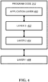
- FIG. 4 is a simplified block diagram of the program code 312 shown in FIG. 3 in accordance with one embodiment of the invention.
- the program code 312 includes an application layer 400, a Layer 3 portion 402, and a Layer 2 portion 404, and is coupled to a Layer 1 portion 406.
- the Layer 3 portion 402 generally performs radio resource control.
- the Layer 2 portion 404 generally performs link control.
- the Layer 1 portion 406 generally performs physical connections.
- the UE may use Discontinuous Reception (DRX) in RRC_IDLE and RRC_INACTIVE state in order to reduce power consumption.
- DRX Discontinuous Reception
- the UE monitors one paging occasion (PO) per DRX cycle.
- a PO is a set of PDCCH monitoring occasions and can consist of multiple time slots (e.g. subframe or OFDM symbol) where paging DCI can be sent (TS 38.213 [4]).
- One Paging Frame (PF) is one Radio Frame and may contain one or multiple PO(s) or starting point of a PO.
- the UE assumes that the same paging message is repeated in all transmitted beams and thus the selection of the beam(s) for the reception of the paging message is up to UE implementation.
- the paging message is same for both RAN initiated paging and CN initiated paging.
- the UE initiates RRC Connection Resume procedure upon receiving RAN initiated paging. If the UE receives a CN initiated paging in RRC_INACTIVE state, the UE moves to RRC_IDLE and informs NAS.
- the PF and PO for paging are determined by the following formulae:
- the PDCCH monitoring occasions for paging are determined according to pagingSearchSpace as specified in TS 38.213 [4] and firstPDCCH-MonitoringOccasionOfPO if configured as specified in TS 38.331 [3].
- SearchSpaceld 0 is configured for pagingSearchSpace
- the PDCCH monitoring occasions for paging are same as for RMSI as defined in clause 13 in TS 38.213 [4].
- Ns is either 1 or 2.
- a PO is a set of 'S' consecutive PDCCH monitoring occasions where 'S' is the number of actual transmitted SSBs determined according to ssb-PositionsInBurst in SIB1.
- the K th PDCCH monitoring occasion for paging in the PO corresponds to the K th transmitted SSB.
- the PDCCH monitoring occasions for paging which do not overlap with UL symbols are sequentially numbered from zero starting from the first PDCCH monitoring occasion for paging in the PF.
- the starting PDCCH monitoring occasion number of (i_s + 1) th PO is the (i_s + 1) th value of the firstPDCCH-MonitoringOccasionOfPO parameter; otherwise, it is equal to i_s ⁇ S.
- Ns, nAndPagingFrameOffset, and the length of default DRX Cycle are signaled in SIB1.
- the values of N and PF_offset are derived from the parameter nAndPagingFrameOffset as defined in TS 38.331 [3].
- the parameter first-PDCCH-MonitoringOccasionOfPO is signalled in SIB1 for paging in initial DL BWP. For paging in a DL BWP other than the initial DL BWP, the parameter first-PDCCH-MonitoringOccasionOfPO is signaled in the corresponding BWP configuration.
- 5G-S-TMSI is a 48 bit long bit string as defined in TS 23.501 [10]. 5G-S-TMSI shall in the formulae above be interpreted as a binary number where the left most bit represents the most significant bit.
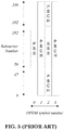
- 3GPP TS 38.300 introduced SSB as shown below, and the structure of SSB is shown in FIG. 5 (which is a reproduction of Figure 5.2.4-1 of 3GPP TS 38.300 V15.5.0, entitled "Time-frequency structure of SSB"):
- the Synchronization Signal and PBCH block consists of primary and secondary synchronization signals (PSS, SSS), each occupying 1 symbol and 127 subcarriers, and PBCH spanning across 3 OFDM symbols and 240 subcarriers, but on one symbol leaving an unused part in the middle for SSS as show in Figure 5.2.4-1.
- PSS, SSS primary and secondary synchronization signals
- PBCH PBCH spanning across 3 OFDM symbols and 240 subcarriers, but on one symbol leaving an unused part in the middle for SSS as show in Figure 5.2.4-1.
- the possible time locations of SSBs within a half-frame are determined by sub-carrier spacing and the periodicity of the half-frames where SSBs are transmitted is configured by the network.
- different SSBs may be transmitted in different spatial directions (i.e. using different beams, spanning the coverage area of a cell).
- multiple SSBs can be transmitted.
- the PCIs of SSBs transmitted in different frequency locations do not have to be unique, i.e. different SSBs in the frequency domain can have different PCIs.
- the SSB corresponds to an individual cell, which has a unique NCGI (see subclause 8.2).
- Such an SSB is referred to as a Cell-Defining SSB (CD-SSB).
- CD-SSB Cell-Defining SSB
- a PCell is always associated to a CD-SSB located on the synchronization raster.
- the UE would perform a beam failure recovery procedure to find a qualified beam as discussed in 3GPP TS 38.300 as follows:
- the gNB configures the UE with beam failure detection reference signals (SSB or CSI-RS) and the UE declares beam failure when the number of beam failure instance indications from the physical layer reaches a configured threshold before a configured timer expires.
- SSB beam failure detection reference signals
- CSI-RS beam failure detection reference signals
- SSB-based Beam Failure Detection is based on the SSB associated to the initial DL BWP and can only be configured for the initial DL BWPs and for DL BWPs containing the SSB associated to the initial DL BWP. For other DL BWPs, Beam Failure Detection can only be performed based on CSI-RS.
- the UE After beam failure is detected, the UE:
- quality of a cell is also determined based on quality of beam(s) of the cell. If a serving cell of the UE (e.g. PCell) is considered as radio link failure, the UE would perform a RRC re-establishment procedure to find a suitable cell to re-establish RRC connection as discussed in 3GPP TS 38.300 as follows:
- the UE performs Radio Link Monitoring (RLM) in the active BWP based on reference signals (SSB/CSI-RS) and signal quality thresholds configured by the network.
- RLM Radio Link Monitoring
- SSB-based RLM is based on the SSB associated to the initial DL BWP and can only be configured for the initial DL BWP and for DL BWPs containing the SSB associated to the initial DL BWP.
- RLM can only be performed based on CSI-RS.
- the UE declares Radio Link Failure (RLF) when one of the following criteria are met:
- the UE After RLF is declared, the UE:
- One of the objectives in the study item for multi-USIM devices is to avoid paging collisions occurring in the UE between different USIMs.
- a PO Paging Occasion
- PDCCH Physical Downlink Control Channel
- overlap in time domain
- the UE has single Rx and the UE needs to monitor paging for these USIMs (e.g.
- the paging associated with one USIM may be delivered to the UE while the UE is communicating with the system associated with another USIM (e.g. USIM B), and the UE may miss a paging due to the collision or overlap.
- POs and/or PDCCH monitoring occasions for paging associated with USIM A may overlap with transmission timing of other signaling, e.g. SSB and/or CSI-RS, associated with USIM B.
- the UE may not be able to monitor paging with USIM A and other signaling (e.g. SSB, CSI-RS) with USIM B simultaneously, and the UE may either miss a paging associated with USIM A or SSB/CSI-RS associated with USIM B. Missing of SSB/CSI-RS may result in beam failure and/or radio link failure. Then, connectivity in 3GPP system associated with USIM B is interrupted.
- the concept of the invention is that for a UE with multiple USIMs, including a first USIM and a second USIM, the UE could provide information, related to paging monitoring (associated with the first USIM), to a network node associated with the second USIM.
- An example is shown in FIG. 6 .
- the UE could provide information, related to collision of paging monitoring (associated with the first USIM), to a network node associated with the first USIM.
- the UE could provide information, related to collision of paging monitoring (associated with the first USIM), to a network node associated with the second USIM.
- FIG. 7 An example is shown in FIG. 7 .
- the information could assist the network associated with one USIM to schedule the timing of transmitting paging and/or other signaling (such as SSB or CSI-RS) such that the transmission will not be collided with some communication (e.g. paging, SSB transmission, CSI-RS transmission) associated with other USIM.
- paging paging
- SSB transmission SSB transmission
- CSI-RS transmission some communication
- the information could indicate one or multiple of following:
- the UE could provide the information in response to one or multiple of following events (e.g. the UE could provide the information upon occurrence of one or multiple of the following events):
- the information could be provided in one or multiple of following signaling:
- the UE may provide the information due to the collision of paging monitoring associated with the first USIM.
- the UE may provide the information regardless of the collision of paging monitoring associated with the first USIM, e.g. the UE provides the information even if there is no collision of paging monitoring associated with the first USIM.
- the UE may need to establish or resume a RRC (Radio Resource Control) connection in order to provide the information.
- RRC Radio Resource Control
- the UE could provide the information if the first USIM and the second USIM are from different MNOs (Mobile Network Operators). The UE may not need to provide the information if the first USIM and the second USIM are from the same MNO.
- MNOs Mobile Network Operators
- the UE could provide the information if the UE has single Rx.
- the UE could provide the information if the first USIM and second USIM share one single Rx.
- the UE may not need to provide the information if the UE has dual Rx.
- the UE may not need to provide the information if the first USIM and second USIM use different Rx.
- the paging could be a signaling transmitted on PDCCH addressed to P-RNTI (Paging Radio Network Temporary Identifier).
- P-RNTI Paging Radio Network Temporary Identifier
- the paging monitoring could be performed in a serving cell associated with the first USIM.
- RRC state associated with the first USIM could be RRC_IDLE.
- RRC state associated with the first USIM could be RRC_INACTIVE.
- RRC state associated with the second USIM could be RRC_IDLE.
- RRC state associated with the second USIM could be RRC_INACTIVE.
- RRC state associated with the second USIM could be RRC_CONNECTED.
- the UE_ID could be IMSI.
- the UE_ID could be 5G-S-TMSI.
- the network node associated with a specific USIM of the UE e.g. the first USIM or the second USIM, could adjust timing of transmitting paging and/or signaling, e.g. in a serving cell associated with the specific USIM, to prevent the (possible) collision.
- the network node could reconfigure value(s) of parameter(s) used by the UE to calculate timing of the paging monitoring associated with the specific USIM.
- the network node could provide parameter(s) used by the UE to shift timing of the paging monitoring associated with the specific USIM.
- the parameter(s) could be used to calculate paging frame(s), paging occasion(s), and/or PDCCH monitoring occasion(s).
- the parameter(s) could be reconfigured by a dedicated signaling.
- the parameter(s) could include PF_offset, T, N, Ns, nAndPagingFrameOffset, and/or UE_ID.
- the parameter(s) could include pagingSearchSpace,firstPDCCH-MonitoringOccasionOfPO, and/or the number of actual transmitted SSBs in a serving cell associated with the specific USIM.
- the network node could reconfigure the UE about timing of reception of signaling associated with the specific USIM.
- the network could handover the UE to another serving cell with different timing of reception of signaling associated with the specific USIM.
- the signaling could be SSB.
- the signaling could be (periodic) CSI-RS.
- the network node could adjust the timing by one or multiple of following signaling:
- the network node could skip transmission of paging in paging occasion(s) with the collision.
- the network node could transmit paging in paging occasion(s) without the collision. Then, the network node may not need to reconfigure value(s) of parameter(s) used by the UE to calculate timing of the paging monitoring associated with the specific USIM.
- the network node could be a RAN node or a CN node.
- the network node could be a base station, eNB, gNB, or AMF
- FIG. 9 is a flow chart 900 according to one exemplary embodiment from the perspective of a UE with a first USIM and a second USIM.
- the UE performs paging monitoring in a first serving cell associated with the first USIM.
- the UE performs paging monitoring in a second serving cell associated with the second USIM.
- the UE transmits, to a network node associated with the second USIM, information related to at least one of the paging monitoring performed in the first serving cell or the paging monitoring performed in the second serving cell.
- the information could indicate occurrence of collision between the paging monitoring performed in the first serving cell and the paging monitoring performed in the second serving cell.
- the information could indicate: (1) timing of the paging monitoring performed in the first serving cell, (2) value(s) of parameter(s) used to calculate timing of the paging monitoring performed in the first serving cell, (3) suggested timing of the paging monitoring performed in the second serving cell, and/or (4) at least one suggested value of at least one parameter used to calculate timing of the paging monitoring performed in the second serving cell.
- the information could be transmitted in response to occurrence of collision between the paging monitoring performed in the first serving cell and the paging monitoring performed in the second serving cell.
- the information could be transmitted in response to timing change of the paging monitoring performed in the first serving cell.
- the information could be transmitted during a RRC connection establishment procedure, or a RRC (Radio Resource Control) connection resume procedure.
- the device 300 includes a program code 312 stored in the memory 310.
- the CPU 308 could execute program code 312 to enable the UE (i) to perform paging monitoring in a first serving cell associated with the first USIM, (ii) to perform paging monitoring in a second serving cell associated with the second USIM, and (iii) to transmit, to a network node associated with the second USIM, information related to at least one of the paging monitoring performed in the first serving cell or the paging monitoring performed in the second serving cell.
- the CPU 308 can execute the program code 312 to perform all of the above-described actions and steps or others described herein.
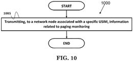
- FIG. 10 is a flow chart 1000 according to one exemplary embodiment from the perspective of a UE with a first USIM and a second USIM.
- the UE transmits, to a network node associated with a specific USIM, information related to paging monitoring.
- the paging monitoring could be performed in a serving cell associated with the first USIM, or in a serving cell associated with the second USIM.
- the information could indicate: (i) timing of the paging monitoring, (ii) paging frame(s) of the paging monitoring, (iii) paging occasion(s) of the paging monitoring, (iv) PDCCH monitoring occasion(s) of the paging monitoring, (v) value(s) of parameter(s) used to calculate timing of the paging monitoring, and/or (vi) suggested value(s) of parameter(s) used to calculate timing of the paging monitoring.
- the parameter(s) could include PF_offset, T, N or Ns, and/or UE ID.
- the information could indicate: (i) suggested timing of the paging monitoring, (ii) occurrence of collision of the paging monitoring, (iii) relief of collision of the paging monitoring, and/or (iv) SFN (System Frame Number) of a serving cell where the paging monitoring is performed.
- SFN System Frame Number
- the device 300 includes a program code 312 stored in the memory 310.
- the CPU 308 could execute program code 312 to enable the UE to transmit, to a network node associated with a specific USIM, information related to paging monitoring. Furthermore, the CPU 308 can execute the program code 312 to perform all of the above-described actions and steps or others described herein.
- FIG. 11 is a flow chart 1100 according to one exemplary embodiment from the perspective of a UE with a first USIM and a second USIM.
- the UE performs paging monitoring in a serving cell associated with the first USIM.
- the UE transmits, to a network node associated with the second USIM, information related to suggested timing of reception of signaling in a serving cell associated with the second USIM based on timing of the paging monitoring.
- the signaling could include SSB.
- the signaling could include periodic CSI-RS.
- the device 300 includes a program code 312 stored in the memory 310.
- the CPU 308 could execute program code 312 to enable the UE (i) to perform paging monitoring in a serving cell associated with the first USIM, and (ii) to transmit, to a network node associated with the second USIM, information related to suggested timing of reception of signaling in a serving cell associated with the second USIM based on timing of the paging monitoring.
- the CPU 308 can execute the program code 312 to perform all of the above-described actions and steps or others described herein.
- the specific USIM could be the first USIM or the second USIM.
- the information could be transmitted in response to (i) occurrence of collision of the paging monitoring, (ii) relief of collision of the paging monitoring, (iii) timing change of the paging monitoring, (iv) enabling of the paging monitoring, (v) disabling of the paging monitoring, (vi) reception of a request from the network node, and/or (vii) serving cell change, e.g. due to handover or cell reselection.
- the information could be transmitted (i) during a RRC connection establishment procedure (as discussed in 3GPP TS 38.331), (ii) during a RRC connection resume procedure (as discussed in 3GPP TS 38.331), (iii) during an AS (Access Stratum) security activation procedure (as discussed in 3GPP TS 38.331), (iv) during a RRC connection re-establishment procedure (as discussed in 3GPP TS 38.331), (v) during a RRC connection reconfiguration procedure (as discussed in 3GPP TS 38.331), or (vi) during a registration procedure (as discussed in 3GPP TS 24.501).
- the first USIM and the second USIM could belong to different MNOs.
- the collision could be due to overlap between paging monitoring associated with the first USIM and paging monitoring associated with the second USIM in time domain, or due to overlap between paging monitoring associated with the first USIM and reception of the signaling associated with the second USIM in time domain.
- timing of paging monitoring associated with one USIM of a UE colliding with timing of signaling reception, such as paging, SSB, and/or CSI-RS, associated with another USIM of the UE can be prevented.
- concurrent channels could be established based on pulse repetition frequencies.
- concurrent channels could be established based on pulse position or offsets.
- concurrent channels could be established based on time hopping sequences.
- concurrent channels could be established based on pulse repetition frequencies, pulse positions or offsets, and time hopping sequences.
- the various illustrative logical blocks, modules, and circuits described in connection with the aspects disclosed herein may be implemented within or performed by an integrated circuit ("IC"), an access terminal, or an access point.
- the IC may comprise a general purpose processor, a digital signal processor (DSP), an application specific integrated circuit (ASIC), a field programmable gate array (FPGA) or other programmable logic device, discrete gate or transistor logic, discrete hardware components, electrical components, optical components, mechanical components, or any combination thereof designed to perform the functions described herein, and may execute codes or instructions that reside within the IC, outside of the IC, or both.
- a general purpose processor may be a microprocessor, but in the alternative, the processor may be any conventional processor, controller, microcontroller, or state machine.
- a processor may also be implemented as a combination of computing devices, e.g., a combination of a DSP and a microprocessor, a plurality of microprocessors, one or more microprocessors in conjunction with a DSP core, or any other such configuration.
- a software module e.g., including executable instructions and related data
- other data may reside in a data memory such as RAM memory, flash memory, ROM memory, EPROM memory, EEPROM memory, registers, a hard disk, a removable disk, a CD-ROM, or any other form of computer-readable storage medium known in the art.
- a sample storage medium may be coupled to a machine such as, for example, a computer/processor (which may be referred to herein, for convenience, as a "processor") such the processor can read information (e.g., code) from and write information to the storage medium.
- a sample storage medium may be integral to the processor.
- the processor and the storage medium may reside in an ASIC.
- the ASIC may reside in user equipment.
- the processor and the storage medium may reside as discrete components in user equipment.
- any suitable computer-program product may comprise a computer-readable medium comprising codes relating to one or more of the aspects of the disclosure.
- a computer program product may comprise packaging materials.
Landscapes
- Engineering & Computer Science (AREA)
- Computer Networks & Wireless Communication (AREA)
- Signal Processing (AREA)
- Computer Security & Cryptography (AREA)
- Databases & Information Systems (AREA)
- Mobile Radio Communication Systems (AREA)
Applications Claiming Priority (1)
| Application Number | Priority Date | Filing Date | Title |
|---|---|---|---|
| US201962850749P | 2019-05-21 | 2019-05-21 |
Publications (1)
| Publication Number | Publication Date |
|---|---|
| EP3742831A1 true EP3742831A1 (de) | 2020-11-25 |
Family
ID=70333831
Family Applications (1)
| Application Number | Title | Priority Date | Filing Date |
|---|---|---|---|
| EP20170292.5A Pending EP3742831A1 (de) | 2019-05-21 | 2020-04-20 | Verfahren und vorrichtung zur vermeidung von paging-kollisionen in einem drahtlosen kommunikationssystem |
Country Status (4)
| Country | Link |
|---|---|
| US (1) | US11864157B2 (de) |
| EP (1) | EP3742831A1 (de) |
| KR (1) | KR102328222B1 (de) |
| CN (1) | CN111988846B (de) |
Cited By (7)
| Publication number | Priority date | Publication date | Assignee | Title |
|---|---|---|---|---|
| WO2021102786A1 (en) | 2019-11-28 | 2021-06-03 | Apple Inc. | Adjust paging occasion to resolve paging collision at multi-sim device |
| WO2021204548A1 (en) * | 2020-04-08 | 2021-10-14 | Nokia Technologies Oy | Ue assisted paging enhancements for multi-usim devices |
| EP3890412A4 (de) * | 2018-11-30 | 2022-08-31 | LG Electronics Inc. | Verfahren zum senden und empfangen eines funkrufsignals in einem drahtloskommunikationssystem und vorrichtung dafür |
| EP4030868A4 (de) * | 2019-09-30 | 2022-09-14 | Huawei Technologies Co., Ltd. | Funkrufverfahren und -vorrichtung |
| EP3981207A4 (de) * | 2019-06-05 | 2023-01-18 | Lenovo (Beijing) Limited | Verfahren und vorrichtung zur behandlung von paging-kollisionen |
| US11595940B1 (en) | 2021-09-29 | 2023-02-28 | Qualcomm Incorporated | Paging collision avoidance in a multi-subscriber identity module (MSIM) user equipment, and associated devices, systems, and methods |
| WO2023114672A1 (en) * | 2021-12-17 | 2023-06-22 | Qualcomm Incorporated | Methods to avoid sounding reference signal suspension due to multi-subscriber paging occasion collision |
Families Citing this family (14)
| Publication number | Priority date | Publication date | Assignee | Title |
|---|---|---|---|---|
| US11368937B2 (en) | 2019-04-12 | 2022-06-21 | Ofinno, Llc | Paging time adjustment in a wireless network |
| CN112243292B (zh) * | 2019-07-17 | 2022-01-14 | 华为技术有限公司 | 一种通信方法及装置 |
| GB2588501B (en) * | 2019-08-06 | 2021-12-29 | Samsung Electronics Co Ltd | Improvements in and relating to paging in a multi-USIM user equipment |
| WO2021029580A1 (ko) * | 2019-08-09 | 2021-02-18 | 엘지전자 주식회사 | 다중 usim을 지원하는 사용자 장치의 동작 방법 |
| WO2021155583A1 (en) * | 2020-02-07 | 2021-08-12 | Telefonaktiebolaget Lm Ericsson (Publ) | Network device and method therein |
| US11483797B2 (en) * | 2020-02-12 | 2022-10-25 | Charter Communications Operating, Llc | Paging notification conflict and management in multiple wireless networks |
| US11659379B2 (en) * | 2020-10-02 | 2023-05-23 | Qualcomm Incorporated | Dynamic capacity for multiple universal subscriber identity modules |
| WO2022154518A1 (en) * | 2021-01-13 | 2022-07-21 | Samsung Electronics Co., Ltd. | Paging collision avoidance by ue comprising plurality of rat networks and sims in cellular network |
| CN114765824A (zh) * | 2021-01-15 | 2022-07-19 | 展讯通信(上海)有限公司 | 传输数据的方法及装置、存储介质、ue、第一接入网设备 |
| WO2022191519A1 (en) | 2021-03-11 | 2022-09-15 | Samsung Electronics Co., Ltd. | Method for selecting cell using a 5g user equipment and a 5g ue |
| CN115349283B (zh) * | 2021-03-12 | 2024-04-30 | 北京小米移动软件有限公司 | 配置信息发送方法和装置、配置确定方法和装置 |
| WO2022205314A1 (zh) * | 2021-04-01 | 2022-10-06 | 北京小米移动软件有限公司 | 寻呼原因处理方法及装置、通信设备及存储介质 |
| US12028816B2 (en) * | 2021-11-10 | 2024-07-02 | Qualcomm Incorporated | Systems and methods to adjust a sounding reference signal timing offset |
| WO2024010420A1 (en) * | 2022-07-08 | 2024-01-11 | Lg Electronics Inc. | Conflict resolution in wireless communication system |
Citations (1)
| Publication number | Priority date | Publication date | Assignee | Title |
|---|---|---|---|---|
| WO2020124057A1 (en) * | 2018-12-14 | 2020-06-18 | Qualcomm Incorporated | Resolution of paging collisions in multisim and c-rat operation |
Family Cites Families (11)
| Publication number | Priority date | Publication date | Assignee | Title |
|---|---|---|---|---|
| US8862145B2 (en) | 2010-04-05 | 2014-10-14 | Qualcomm Incorporated | Method and apparatus to improvie idle mode power consumption in multiple USIM configuration |
| US8977261B2 (en) | 2010-08-11 | 2015-03-10 | Qualcomm Incorporated | Hardware activation of dual USIM multimode mobile terminal |
| US8964663B2 (en) * | 2011-01-06 | 2015-02-24 | Qualcomm Incorporated | Method and apparatus for signaling paging configurations and channel state information reference signal (CSI-RS) configurations |
| EP2737762B1 (de) * | 2011-07-25 | 2018-05-30 | Telefonaktiebolaget LM Ericsson (publ) | Funkrufempfang bei drahtlosen kommunikationsgeräten mit dual-sim |
| EP2818012B1 (de) * | 2012-02-24 | 2021-09-22 | Deutsche Telekom AG | Verfahren zum paging eines benutzergeräts aus einem ersten öffentlichen landfunknetz und aus einem zweiten öffentlichen landfunknetz, benutzergerät, programm und computerprogrammprodukt |
| US20150163827A1 (en) * | 2013-12-06 | 2015-06-11 | Broadcom Corporation | Apparatus and Method for Paging for Mutli-Standby Devices |
| US10492169B2 (en) * | 2017-06-15 | 2019-11-26 | Qualcomm Incorporated | Mitigating page collisions in dual subscriber identity module devices |
| CN115835288A (zh) | 2017-10-21 | 2023-03-21 | 上海朗帛通信技术有限公司 | 一种无线通信的用户设备、网络设备中的方法和装置 |
| KR102351399B1 (ko) * | 2018-02-23 | 2022-01-14 | 삼성전자 주식회사 | 복수의 가입자 식별 모듈들을 사용하는 전자 장치 및 그의 통신 서비스 제공 방법 |
| US11917580B2 (en) * | 2018-11-30 | 2024-02-27 | Lg Electronics Inc. | Method for transmitting and receiving paging signal in wireless communication system and apparatus therefor |
| WO2020223978A1 (zh) * | 2019-05-09 | 2020-11-12 | Oppo广东移动通信有限公司 | 无线通信方法、网络设备和终端设备 |
-
2020
- 2020-04-20 KR KR1020200047667A patent/KR102328222B1/ko active IP Right Grant
- 2020-04-20 EP EP20170292.5A patent/EP3742831A1/de active Pending
- 2020-04-20 CN CN202010311933.8A patent/CN111988846B/zh active Active
- 2020-04-20 US US16/853,116 patent/US11864157B2/en active Active
Patent Citations (1)
| Publication number | Priority date | Publication date | Assignee | Title |
|---|---|---|---|---|
| WO2020124057A1 (en) * | 2018-12-14 | 2020-06-18 | Qualcomm Incorporated | Resolution of paging collisions in multisim and c-rat operation |
Non-Patent Citations (1)
| Title |
|---|
| QUALCOMM INCORPORATED ET AL: "Avoidance of paging collisions to minimize outage of services", vol. SA WG2, no. San Jose Del Cabo; 20170626 - 20170630, 25 June 2017 (2017-06-25), XP051303098, Retrieved from the Internet <URL:http://www.3gpp.org/ftp/Meetings_3GPP_SYNC/SA2/Docs/> [retrieved on 20170625] * |
Cited By (11)
| Publication number | Priority date | Publication date | Assignee | Title |
|---|---|---|---|---|
| EP3890412A4 (de) * | 2018-11-30 | 2022-08-31 | LG Electronics Inc. | Verfahren zum senden und empfangen eines funkrufsignals in einem drahtloskommunikationssystem und vorrichtung dafür |
| US11917580B2 (en) | 2018-11-30 | 2024-02-27 | Lg Electronics Inc. | Method for transmitting and receiving paging signal in wireless communication system and apparatus therefor |
| EP3981207A4 (de) * | 2019-06-05 | 2023-01-18 | Lenovo (Beijing) Limited | Verfahren und vorrichtung zur behandlung von paging-kollisionen |
| EP4030868A4 (de) * | 2019-09-30 | 2022-09-14 | Huawei Technologies Co., Ltd. | Funkrufverfahren und -vorrichtung |
| WO2021102786A1 (en) | 2019-11-28 | 2021-06-03 | Apple Inc. | Adjust paging occasion to resolve paging collision at multi-sim device |
| EP4066582A4 (de) * | 2019-11-28 | 2023-07-26 | Apple Inc. | Einstellen von paging-gelegenheiten, um paging-kollisionen bei multi-sim-geräten zu lösen |
| WO2021204548A1 (en) * | 2020-04-08 | 2021-10-14 | Nokia Technologies Oy | Ue assisted paging enhancements for multi-usim devices |
| US11595940B1 (en) | 2021-09-29 | 2023-02-28 | Qualcomm Incorporated | Paging collision avoidance in a multi-subscriber identity module (MSIM) user equipment, and associated devices, systems, and methods |
| WO2023055627A1 (en) * | 2021-09-29 | 2023-04-06 | Qualcomm Incorporated | Paging collision avoidance in a multi-sim user equipment |
| WO2023114672A1 (en) * | 2021-12-17 | 2023-06-22 | Qualcomm Incorporated | Methods to avoid sounding reference signal suspension due to multi-subscriber paging occasion collision |
| US11849421B2 (en) | 2021-12-17 | 2023-12-19 | Qualcomm Incorporated | Methods to avoid sounding reference signal suspension due to multi-subscriber paging occasion collision |
Also Published As
| Publication number | Publication date |
|---|---|
| CN111988846B (zh) | 2023-05-09 |
| US11864157B2 (en) | 2024-01-02 |
| KR20200135164A (ko) | 2020-12-02 |
| CN111988846A (zh) | 2020-11-24 |
| US20200374833A1 (en) | 2020-11-26 |
| KR102328222B1 (ko) | 2021-11-18 |
Similar Documents
| Publication | Publication Date | Title |
|---|---|---|
| EP3742831A1 (de) | Verfahren und vorrichtung zur vermeidung von paging-kollisionen in einem drahtlosen kommunikationssystem | |
| US11228899B2 (en) | Method and apparatus for multiple-USIM device in a wireless communication system | |
| CN113692752B (zh) | 一种无线连接活动信息更新方法和装置 | |
| US11496886B2 (en) | Method and apparatus for connection control in a wireless communication system | |
| EP2887711B1 (de) | Verfahren und vorrichtung zur unterstützung von vorrichtung-zu-vorrichtung (d2d)-erfassung in einem drahtlosen kommunikationssystem | |
| EP3941136A1 (de) | Verfahren und vorrichtung zur auswahl von bwp für eine nachfolgende übertragung in vorkonfigurierten ressourcen auf der basis von sdt in einem drahtlosen kommunikationssystem | |
| US11910482B2 (en) | Method and apparatus for UE reporting for multi-USIM in a wireless communication system | |
| EP4013182A1 (de) | Verfahren und vorrichtung zur konfiguration des diskontinuierlichen sidelink-empfangs in einem drahtlosen kommunikationssystem | |
| EP4002953A1 (de) | Verfahren und vorrichtung zur erfassung von systeminformationen und zum paging über ein benutzergerät-netzwerkrelais in einem drahtlosen kommunikationssystem | |
| US20130182626A1 (en) | Method and apparatus for reducing user equipment (ue) power consumption in the rrc (radio resource control) connected mode | |
| EP3972368A1 (de) | Verfahren und vorrichtung für prozess der übertragung kleiner daten (sdt) in einem drahtloskommunikationssystem | |
| US20140112271A1 (en) | Method and apparatus to implement discontinuous reception (drx) in a wireless communication system | |
| EP4013183A1 (de) | Verfahren und vorrichtung zur konfiguration des diskontinuierlichen sidelink-empfangs in einem drahtlosen kommunikationssystem | |
| CN116806053A (zh) | 无线通信系统中用于移动终止的小数据传送的方法和设备 | |
| US20230180148A1 (en) | Method and apparatus for power headroom reporting for multi-subscriber identity module (sim) in a wireless communication system |
Legal Events
| Date | Code | Title | Description |
|---|---|---|---|
| PUAI | Public reference made under article 153(3) epc to a published international application that has entered the european phase |
Free format text: ORIGINAL CODE: 0009012 |
|
| STAA | Information on the status of an ep patent application or granted ep patent |
Free format text: STATUS: THE APPLICATION HAS BEEN PUBLISHED |
|
| AK | Designated contracting states |
Kind code of ref document: A1 Designated state(s): AL AT BE BG CH CY CZ DE DK EE ES FI FR GB GR HR HU IE IS IT LI LT LU LV MC MK MT NL NO PL PT RO RS SE SI SK SM TR |
|
| AX | Request for extension of the european patent |
Extension state: BA ME |
|
| STAA | Information on the status of an ep patent application or granted ep patent |
Free format text: STATUS: REQUEST FOR EXAMINATION WAS MADE |
|
| 17P | Request for examination filed |
Effective date: 20210223 |
|
| RBV | Designated contracting states (corrected) |
Designated state(s): AL AT BE BG CH CY CZ DE DK EE ES FI FR GB GR HR HU IE IS IT LI LT LU LV MC MK MT NL NO PL PT RO RS SE SI SK SM TR |
|
| STAA | Information on the status of an ep patent application or granted ep patent |
Free format text: STATUS: EXAMINATION IS IN PROGRESS |
|
| 17Q | First examination report despatched |
Effective date: 20220224 |