EP3742598A1 - Drive device, fluid utilization device, and air conditioner - Google Patents
Drive device, fluid utilization device, and air conditioner Download PDFInfo
- Publication number
- EP3742598A1 EP3742598A1 EP18901287.5A EP18901287A EP3742598A1 EP 3742598 A1 EP3742598 A1 EP 3742598A1 EP 18901287 A EP18901287 A EP 18901287A EP 3742598 A1 EP3742598 A1 EP 3742598A1
- Authority
- EP
- European Patent Office
- Prior art keywords
- current
- synchronous motor
- pulsating component
- drive system
- torque
- Prior art date
- Legal status (The legal status is an assumption and is not a legal conclusion. Google has not performed a legal analysis and makes no representation as to the accuracy of the status listed.)
- Granted
Links
Images








Classifications
-
- H—ELECTRICITY
- H02—GENERATION; CONVERSION OR DISTRIBUTION OF ELECTRIC POWER
- H02P—CONTROL OR REGULATION OF ELECTRIC MOTORS, ELECTRIC GENERATORS OR DYNAMO-ELECTRIC CONVERTERS; CONTROLLING TRANSFORMERS, REACTORS OR CHOKE COILS
- H02P5/00—Arrangements specially adapted for regulating or controlling the speed or torque of two or more electric motors
- H02P5/46—Arrangements specially adapted for regulating or controlling the speed or torque of two or more electric motors for speed regulation of two or more dynamo-electric motors in relation to one another
- H02P5/50—Arrangements specially adapted for regulating or controlling the speed or torque of two or more electric motors for speed regulation of two or more dynamo-electric motors in relation to one another by comparing electrical values representing the speeds
-
- H—ELECTRICITY
- H02—GENERATION; CONVERSION OR DISTRIBUTION OF ELECTRIC POWER
- H02P—CONTROL OR REGULATION OF ELECTRIC MOTORS, ELECTRIC GENERATORS OR DYNAMO-ELECTRIC CONVERTERS; CONTROLLING TRANSFORMERS, REACTORS OR CHOKE COILS
- H02P21/00—Arrangements or methods for the control of electric machines by vector control, e.g. by control of field orientation
- H02P21/05—Arrangements or methods for the control of electric machines by vector control, e.g. by control of field orientation specially adapted for damping motor oscillations, e.g. for reducing hunting
-
- H—ELECTRICITY
- H02—GENERATION; CONVERSION OR DISTRIBUTION OF ELECTRIC POWER
- H02P—CONTROL OR REGULATION OF ELECTRIC MOTORS, ELECTRIC GENERATORS OR DYNAMO-ELECTRIC CONVERTERS; CONTROLLING TRANSFORMERS, REACTORS OR CHOKE COILS
- H02P21/00—Arrangements or methods for the control of electric machines by vector control, e.g. by control of field orientation
- H02P21/14—Estimation or adaptation of machine parameters, e.g. flux, current or voltage
- H02P21/18—Estimation of position or speed
-
- H—ELECTRICITY
- H02—GENERATION; CONVERSION OR DISTRIBUTION OF ELECTRIC POWER
- H02P—CONTROL OR REGULATION OF ELECTRIC MOTORS, ELECTRIC GENERATORS OR DYNAMO-ELECTRIC CONVERTERS; CONTROLLING TRANSFORMERS, REACTORS OR CHOKE COILS
- H02P21/00—Arrangements or methods for the control of electric machines by vector control, e.g. by control of field orientation
- H02P21/22—Current control, e.g. using a current control loop
-
- H—ELECTRICITY
- H02—GENERATION; CONVERSION OR DISTRIBUTION OF ELECTRIC POWER
- H02P—CONTROL OR REGULATION OF ELECTRIC MOTORS, ELECTRIC GENERATORS OR DYNAMO-ELECTRIC CONVERTERS; CONTROLLING TRANSFORMERS, REACTORS OR CHOKE COILS
- H02P21/00—Arrangements or methods for the control of electric machines by vector control, e.g. by control of field orientation
- H02P21/24—Vector control not involving the use of rotor position or rotor speed sensors
- H02P21/26—Rotor flux based control
-
- H—ELECTRICITY
- H02—GENERATION; CONVERSION OR DISTRIBUTION OF ELECTRIC POWER
- H02P—CONTROL OR REGULATION OF ELECTRIC MOTORS, ELECTRIC GENERATORS OR DYNAMO-ELECTRIC CONVERTERS; CONTROLLING TRANSFORMERS, REACTORS OR CHOKE COILS
- H02P5/00—Arrangements specially adapted for regulating or controlling the speed or torque of two or more electric motors
- H02P5/46—Arrangements specially adapted for regulating or controlling the speed or torque of two or more electric motors for speed regulation of two or more dynamo-electric motors in relation to one another
Definitions
- the present invention relates to a drive system that drives two synchronous motors connected in parallel to a single power inverter, a fluid utilization apparatus including the drive system, and an air conditioner including the fluid utilization apparatus.
- a synchronous motor may fail to produce proper torque, and thus lose synchronism or stop its operation unless information on a rotor position that is a rotational position of a rotor is used to apply a proper voltage in accordance with the rotational position.
- the prior art have used the same number of power inverters as the number of synchronous motors to apply a voltage according to a rotational position of a rotor of each of the synchronous motors.
- this configuration poses a problem of increased cost because the number of power inverters increases as the number of synchronous motors increases.
- the sophistication of synchronous motor control technology have made attempts to drive two synchronous motors with a single power inverter.
- two synchronous motors which are a main synchronous motor and a secondary synchronous motor, are connected to a single power inverter.
- a drive system controls those two synchronous motors, using rotation speeds of the two synchronous motors.
- the drive system performs vector control on the main synchronous motor, and uses both a difference in rotation speed and a difference in rotation position between the two synchronous motors to determine a d-axis current command for the main synchronous motor, such that the drive of the secondary synchronous motor is stabilized.
- Vector control is a control method in which currents flowing through a synchronous motor are decomposed into a current component generating torque and a current component generating magnetic flux, and the current components are controlled independently.
- Patent Literature 1 US 2015/0,229,245 A Non Patent Literature
- Non Patent Literature 1 Yongjae Lee, Jung-Ik Ha, "Analysis and Control of Mono Inverter Dual Parallel SPMSM Drive System", 2014, IEEE
- Non Patent Literature 2 Yongjae Lee, Jung-Ik Ha, "Control Method for Mono Inverter Dual Parallel Surface-Mounted Permanent-Magnet Synchronous Machine Drive System", 2015, IEEE
- Patent Literature 1 teaches that the technique disclosed in Patent Literature 1 is applicable to position sensorless control that does not use sensors such as speed detection means and position detection means.
- Non Patent Literatures 1 and 2 present the results of verification tests of position sensorless control using the technique of Patent Literature 1.
- position sensorless control is problematic from the standpoint of operation stability in the low-speed range. Such a problem with position sensorless control is that the low-rpm range provides a decreased speed electromotive force of motors, and the influence of output voltage errors of the power inverter becomes relatively large.
- Patent Literature 1 Since the operation stability at low speed is an issue even when a single synchronous motor is driven by a single power inverter, it is more difficult to provide the operation stability in the low-speed range when two synchronous motors are driven in parallel by a single power inverter.
- Patent Literature 1 Non Patent Literature 1, and Non Patent Literature 2 do not specifically describe a drive method in the low-speed range.
- the present invention has been made in view of the above. It is an object of the present invention to provide a drive system that can prevent unstable rotation in the low-speed range even when two synchronous motors are driven in position sensorless control manner, using a single power inverter.
- a drive system of the present invention comprises a power inverter to supply power to a first synchronous motor and a second synchronous motor connected in parallel to each other; a first current detector to detect a first current flowing to the first synchronous motor; and a second current detector to detect a second current flowing to the second synchronous motor.
- the drive system also comprises a first magnetic pole position estimation unit to estimate a first magnetic pole position of a rotor of the first synchronous motor, using a voltage command for driving the first synchronous motor and the first current, and a second magnetic pole position estimation unit to estimate a second magnetic pole position of a rotor of the second synchronous motor, using the voltage command and the second current.
- the drive system further comprises a control unit to output the voltage command, using a torque current command, a magnetic flux current command, the first current, and the first magnetic pole position, and a pulsating component extraction unit to extract at least one of a torque current pulsating component and an active power pulsating component, the torque current pulsating component being contained in a torque current flowing to the second synchronous motor, the active power pulsating component contained in active power consumed by the second synchronous motor.
- the drive system further comprises a first subtracter to determine an angle difference that is a difference between the magnetic pole positions of the rotors of the first synchronous motor and the second synchronous motor, using the first magnetic pole position and the second magnetic pole position, and a magnetic flux current command determination unit to determine the magnetic flux current command, using the pulsating component extracted by the pulsating component extraction unit and the angle difference.
- the present invention has the advantage of preventing the unstable rotation in the low-speed range even when the two synchronous motors are driven in the position sensorless control manner, using the single power inverter.
- FIG. 1 is a diagram illustrating a configuration of a drive system according to a first embodiment of the present invention.
- Synchronous motors are broadly divided into permanent magnet field synchronous motors in which permanent magnets are provided to the rotor, winding field synchronous motors in which field windings are wound on the rotor, and reluctance synchronous motors that obtain running torque using the saliency of the rotor.
- synchronous motors of the same type for example, two permanent magnet field synchronous motors are connected in parallel to a drive system 100 according to the first embodiment.
- one of the two synchronous motors is referred to as a main synchronous motor 1a, and the other is referred to as a secondary synchronous motor 1b.
- the main synchronous motor 1a is a first synchronous motor
- the secondary synchronous motor 1b is a second synchronous motor.
- the drive system 100 includes a power inverter 2, a current detection unit 4a, a current detection unit 4b, and a magnetic pole position estimation unit 5a.
- the power inverter 2 supplies power to the main synchronous motor 1a and the secondary synchronous motor 1b connected in parallel to the main synchronous motor 1a.
- the current detection unit 4a detects a first current flowing to the main synchronous motor 1a.
- the current detection unit 4b detects a second current flowing to the secondary synchronous motor 1b.
- the magnetic pole position estimation unit 5a is a first magnetic pole position estimation unit.
- the drive system 100 further includes a magnetic pole position estimation unit 5b, a current control unit 6, a pulsating component extraction unit 70, a subtracter 8, and a magnetic flux current command determination unit 9.
- the magnetic pole position estimation unit 5b is a second magnetic pole position estimation unit.
- the current control unit 6 is a control unit for outputting a voltage command.
- the subtracter 8 is a first subtracter.
- the pulsating component extraction unit 70 includes a secondary torque current pulsating component extraction unit 7. In the following, the secondary torque current pulsating component extraction unit 7 is sometimes simply referred to as the "pulsating component extraction unit 7".
- the power inverter 2 converts DC power supplied from a DC voltage source 3 into AC power, and outputs the AC power to the main synchronous motor 1a and the secondary synchronous motor 1b.
- a voltage source inverter is used as the power inverter 2.
- the voltage source inverter is a device that switches a DC voltage supplied from the DC voltage source 3, such that the DC voltage is converted into an AC voltage.
- the power inverter 2 is not limited to the voltage source inverter, and may be a circuit such as a current source inverter, a matrix converter that converts AC power into AC power different in amplitude and frequency, or a multi-level inverter in which the outputs of a plurality of inverters are connected in series or in parallel, as long as it can output AC power for driving the main synchronous motor 1a and the secondary synchronous motor 1b.
- the current detection unit 4a that is a first current detector detects phase currents flowing from the power inverter 2 to the main synchronous motor 1a, and outputs current information indicating the values of the detected phase currents.
- the current detection unit 4b that is a second current detector detects phase currents flowing from the power inverter 2 to the secondary synchronous motor 1b, and outputs current information indicating the values of the detected phase currents.
- the current detection units 4a and 4b may be current sensors using an instrument current transformer called a current transformer (CT), or current sensors using a shunt resistor. Alternatively, the current detection units 4a and 4b may be a combination of them.
- CT current transformer
- the current detection units 4a and 4b may be a combination of them.
- currents are detected by the current detection units 4a and 4b provided near the synchronous motors.
- phase currents flowing to the synchronous motors are directly detected
- a current detection method is not limited to the example of direct detection. Any method may be used in which currents flowing to the synchronous motors can be calculated by Kirchhoff's current law.
- a single-shunt current detection method using a shunt resistor provided in a negative DC bus of the power inverter 2 may be used to detect phase currents flowing to the synchronous motors.
- the lower-arm shunt current detection method uses shunt resistors connected in series with three lower arms, and thus is also called a three-shunt current detection method.
- the single-shunt current detection method or the three-shunt current detection method only the total value of currents flowing to the main synchronous motor 1a and the secondary synchronous motor 1b is measured.
- the magnetic pole position estimation unit 5a estimates a first magnetic pole position of the main synchronous motor 1a.
- the first current which is detected by the current detection unit 4a, is the phase currents flowing to the main synchronous motor 1a.
- the voltage command is output from the current control unit 6.
- the magnetic pole position estimation unit 5b estimates a second magnetic pole position of the secondary synchronous motor 1b.
- the second current which is detected by the current detection unit 4b, is the phase currents flowing to the secondary synchronous motor 1b.
- the voltage command is output from the current control unit 6.
- the current control unit 6 is a vector controller that controls a current flowing to the main synchronous motor 1a, by performing vector control for coordinate transformation of the current detected by the current detection unit 4a into a current command value in a d-q coordinate system where the d-axis is the direction of magnetic flux produced by the permanent magnets of the rotor of the main synchronous motor 1a, and the q-axis is an axis orthogonal to the d-axis.
- Common vector controllers control a current on d and q coordinates based on the magnetic poles of the rotor. This is because transformation of phase currents into values on d and q coordinates changes an AC amount into a DC amount, thereby facilitating the control.
- a q-axis current is proportional to the magnet torque of the synchronous motor, and thus the q-axis is referred to as a torque axis, and the q-axis current is referred to as a torque current.
- a d-axis current which causes a change in magnetic flux produced at the stator, changes the amplitude of the output voltage of the synchronous motor.
- the d-axis is referred to as a magnetic flux axis
- the d-axis current is referred to as a magnetic flux current, an exciting current, or the like.
- Types of synchronous motors include surface magnet synchronous AC motors in which permanent magnets are provided on the outer peripheral surface of the rotor core, permanent magnet embedded motors in which permanent magnets are embedded inside the rotor core, etc.
- a d-axis current changes reluctance torque, and thus it is not only a q-axis current that acts on torque.
- the q-axis current is often referred to as a torque current.
- the coordinate transformation uses an estimate value of the magnetic pole position calculated by the magnetic pole position estimation unit 5a.
- the current control unit 6 may use a polar coordinate system, not the d-q coordinate system in vector control. Such a polar coordinate system is, for example, an ⁇ - ⁇ stator coordinate system or a ⁇ - ⁇ coordinate system. Further, the current control unit 6 may employ direct torque control (DTC) instead of vector control. However, if DTC is employed, it is necessary to convert a current command into a magnetic flux command and a torque command.
- DTC direct torque control
- the torque current and the magnetic flux current can be more precisely calculated by the control performed in a coordinate system based on magnetic flux produced from the stator rather than in the d-q coordinate system.
- This coordinate system which is often referred to as, for example, an f-t coordinate system or an n-t coordinate system, is known and thus the details thereof will not be described.
- a q-axis current is sometimes referred to as a torque current and a d-axis current as a magnetic flux current, except where, for example, the control is performed using a coordinate system other than the d-q coordinate system, and reluctance synchronous motors that does not produce magnet torque in theory are used.
- the current control unit 6 performs control such that a torque current flowing to the main synchronous motor 1a matches the value of a torque current command, and that a magnetic flux current flowing to the main synchronous motor 1a matches the value of a magnetic flux current command.
- the current control unit 6 may be actually implemented in any way.
- the current control unit 6 typically includes a proportional-integral controller and a decoupling controller.
- the torque current command may be calculated as a result of speed control in the magnetic flux current command determination unit 9, or may be input from a higher level controller. The details of the magnetic flux current command will be described later.
- ⁇ n is represented by an approximate expression in formula (1) below, where P m represents the number of pole pairs, ⁇ a represents the armature flux linkage, L a represents the armature inductance, and J represents the moment of inertia.
- Electromechanical coupled oscillation is sometimes called electromechanical spring resonance.
- the natural angular frequency ⁇ n expressed by formula (1) above is also called an electromechanical spring resonance angular frequency.
- the technique disclosed in Reference 1 described above is additionally provided with a stabilizing compensator to suppress electromechanical spring resonance.
- the drive system 100 also requires similar stabilizing compensation. It is therefore necessary to check how much a torque current flowing to the secondary synchronous motor 1b illustrated in FIG. 1 oscillates due to the electromechanical spring resonance.
- Patent Literature 1 determines a speed difference that is a difference between the rotation speeds of the rotors of the main synchronous motor and the secondary synchronous motor, and uses such a speed difference to thereby perform speed difference stabilizing compensation. Consequently, the main synchronous motor is controlled stably. Thus, it can be said that the technique disclosed in Patent Literature 1 performs stabilizing compensation by determining a speed pulsating component of the secondary synchronous motor. The details of differences between the technique disclosed in Patent Literature 1 and the first embodiment will be described later.
- the pulsating component extraction unit 7 illustrated in FIG. 1 extracts a pulsating component in the vicinity of the electromechanical spring resonance angular frequency, which component is contained in the torque current of the secondary synchronous motor 1b.
- the pulsating component extraction unit 7 employs two different types of methods: a method using a high-pass filter; and a method using a bandpass filter, which will be described in that order.
- FIG. 2 is a diagram illustrating a first configuration example of the secondary torque current pulsating component extraction unit illustrated in FIG. 1.
- FIG. 2 illustrates a configuration example of a secondary torque current pulsating component extraction unit 7A using a first-order high-pass filter.
- Formula (2) above shows the transfer function when the first-order high-pass filter is used. If sharper filter characteristics are desired, a high-pass filter whose order is n may be used. n is an integer greater than or equal to two.
- the cutoff angular frequency ⁇ c is preferably set to a value lower than or equal to 1/3 the electromechanical spring resonance angular frequency, for example, 1/5 to 1/20 the electromechanical spring resonance angular frequency.
- FIG. 3 is a diagram illustrating a second configuration example of the secondary torque current pulsating component extraction unit illustrated in FIG. 1 .
- FIG. 3 illustrates a configuration example of a secondary torque current pulsating component extraction unit 7B using a second-order bandpass filter.
- the a secondary torque current pulsating component extraction unit 7B has its transfer function represented by formula (3) below, where s represents the Laplace transform operator, and ⁇ p represents the peak angular frequency.
- q is a quality factor and is a coefficient that determines the passband width of the filter. [Formula 3]
- G BPF ⁇ p q s s 2 + ⁇ p q s + ⁇ p 2
- Formula (3) above shows the transfer function when the second-order bandpass filter is used. If sharper filter characteristics are desired, a bandpass filter of order m may be used. m is an integer greater than or equal to three.
- the secondary torque current pulsating component extraction unit 7B matches the peak angular frequency ⁇ p with the electromechanical spring resonance angular frequency.
- the electromechanical spring resonance angular frequency has a tendency to vary depending on drive conditions. Therefore, the passband width of the bandpass filter needs to be designed to be wider to allow for the variation of the electromechanical spring resonance angular frequency.
- the secondary torque current pulsating component extraction unit 7B may be configured to measure the electromechanical spring resonance angular frequency and make the peak angular frequency ⁇ p track the electromechanical spring resonance angular frequency. That is, the secondary torque current pulsating component extraction unit 7B may be configured to dynamically change the center frequency of the bandpass filter. In that case, the passband width can be narrowed.
- the center frequency corresponds to the peak angular frequency ⁇ p .
- FIG. 4 is a diagram illustrating a third configuration example of the secondary torque current pulsating component extraction unit illustrated in FIG. 1 .
- a secondary torque current pulsating component extraction unit 7C illustrated in FIG. 4 includes a pulsation frequency measurement unit 71, a cosine wave generator 72, a sine wave generator 73, a Fourier cosine coefficient calculation unit 74, a Fourier sine coefficient calculation unit 75, and an AC reconstructor 76.
- the secondary torque current pulsating component extraction unit 7 includes a coordinate transformer (not illustrated).
- the coordinate transformer of the secondary torque current pulsating component extraction unit 7 performs coordinate transformation, using the current detected by the current detection unit 4b and the magnetic pole position estimated by the magnetic pole position estimation unit 5b. Using the magnetic pole position estimated by the magnetic pole position estimation unit 5b, the coordinate transformer performs coordinate transformation of the current in the three-phase coordinate system detected by the current detection unit 4b, into a rotating rectangular coordinate system and outputs the converted current.
- the above-described input signal corresponds to the current whose coordinates have been transformed by the coordinate transformer.
- the cosine wave generator 72 generates a cosine wave signal that oscillates at the pulsation frequency
- the sine wave generator 73 generates a sine wave signal that oscillates at the pulsation frequency.
- the Fourier cosine coefficient calculation unit 74 uses the cosine wave signal from the cosine wave generator 72 to perform a Fourier series expansion of the input signal that is the current detected by the current detection unit 4b, such that the Fourier cosine coefficient calculation unit 74 calculates a Fourier cosine coefficient that is the magnitude of a cosine component of the magnitude of a specific frequency component contained in the input signal.
- the Fourier cosine coefficient is a coefficient when an even function having an arbitrary period is expanded in a cos series.
- the Fourier sine coefficient calculation unit 75 uses the sine wave signal from the sine wave generator 73 to calculate a Fourier sine coefficient that is the magnitude of a sine component of the magnitude of the specific frequency component of the input signal.
- the Fourier sine coefficient is a coefficient when an odd function having an arbitrary period is expanded in a sin series.
- the AC reconstructor 76 reconstructs an alternating current, using all of the cosine wave signal from the cosine wave generator 72, the sine wave signal from the sine wave generator 73, the Fourier cosine coefficient obtained by the Fourier series expansion, and the Fourier sine coefficient obtained by the Fourier series expansion.
- a Fourier series expansion is to extract the magnitude and phase of a specific frequency component from an input signal.
- the magnitude of the specific frequency component can be represented by the magnitude of a cosine component and the magnitude of a sine component.
- the phase can be represented by the ratio between the magnitude of the cosine component and the magnitude of the sine component.
- the secondary torque current pulsating component extraction unit 7C illustrated in FIG. 4 can provide the characteristics of a bandpass filter by Fourier series expansions and an inverse transform. In the inverse transform, an alternating current of a specific frequency is output on the basis of the magnitude of the cosine component, the magnitude of the sine component, and the phase of the specific frequency component extracted by the Fourier series expansions.
- a bandpass filter which is a combination of the pulsation frequency measurement unit 71 illustrated in FIG. 4 and formula (3) above, may be used as the pulsating component extraction unit 7 illustrated in FIG. 1 provided that calculation accuracy can be guaranteed.
- the pulsating component extraction unit 7 may be formed by any of the filters illustrated in FIGS. 2 to 4 as long as it can extract a pulsating component in the vicinity of the electromechanical spring resonance angular frequency contained in the torque current of the secondary synchronous motor 1b.
- a high-pass filter is easier to design and mount on a circuit than a bandpass filter. Thus, when importance is placed on simplicity in design and mounting on a circuit, a high-pass filter can be selected. When it is desired to obtain sharp cutoff characteristics, a bandpass filter can be selected.
- the subtracter 8 illustrated in FIG. 1 determines an angle difference that is a difference between the magnetic pole position of the rotor of the main synchronous motor 1a and the magnetic pole position of the rotor of the secondary synchronous motor 1b.
- the magnetic pole positions are equal to the rotation positions or rotation angles of the rotors of the main synchronous motor 1a and the secondary synchronous motor 1b.
- a voltage equation and a torque equation in a steady state of a permanent magnet synchronous motor are shown below.
- the voltage equation is represented by formula (4) below.
- the torque equation is represented by formula (5) below.
- the first term on the right side of formula (5) below represents magnet torque, and the second term represents reluctance torque.
- the magnet torque is proportional to a q-axis current, and the reluctance torque is proportional to the product of a d-axis current and the q-axis current.
- R a represents the armature resistance
- L d represents the d-axis inductance
- L q represents the q-axis inductance
- P m represents the number of pole pairs
- ⁇ a represents the armature flux linkage
- ⁇ e represents the angular velocity
- i d represents the d-axis current
- i q represents the q-axis current
- v d represents a d-axis voltage
- v q represents a q-axis voltage
- t represents produced torque.
- Subscripts " x " of these coefficients are for distinguishing whether the synchronous motor is the main one or the secondary one.
- FIG. 5 is a first diagram for explaining the behavior of torque change of the secondary synchronous motor illustrated in FIG. 1 .
- FIG. 6 is a second diagram for explaining the behavior of torque change of the secondary synchronous motor illustrated in FIG. 1 .
- FIG. 7 is a third diagram for explaining the behavior of torque change of the secondary synchronous motor illustrated in FIG. 1 .
- FIG. 8 is a fourth diagram for explaining the behavior of torque change of the secondary synchronous motor illustrated in FIG. 1 .
- FIG. 9 is a fifth diagram for explaining the behavior of torque change of the secondary synchronous motor illustrated in FIG. 1 .
- FIG. 5 is a first diagram for explaining the behavior of torque change of the secondary synchronous motor illustrated in FIG. 1 .
- FIG. 6 is a second diagram for explaining the behavior of torque change of the secondary synchronous motor illustrated in FIG. 1 .
- FIG. 7 is a third diagram for explaining the behavior of torque change of the secondary synchronous motor illustrated in FIG. 1 .
- FIG. 8 is a fourth diagram for explaining the behavior of torque
- FIG. 10 is a sixth diagram for explaining the behavior of torque change of the secondary synchronous motor illustrated in FIG. 1 .
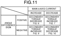
- FIG. 11 is a diagram illustrating a main d-axis current, the signs of the angle difference, and the torque states of the secondary synchronous motor illustrated in FIGS. 6 , 7 , 9 and 10 in association with each other.
- FIGS. 5 to 10 illustrate the behavior of torque change of the secondary synchronous motor 1b due to the magnetic flux current compensation. What is discussed with reference to FIGS. 5 to 10 is disclosed in Patent Literature 1.
- the technique disclosed in Patent Literature 1 and the drive system 100 according to the first embodiment are the same in that the angle difference between the magnetic pole positions of the rotors of the main synchronous motor 1a and the secondary synchronous motor 1b is used in control for stabilizing the drive of the secondary synchronous motor 1b.
- the drive system 100 according to the first embodiment differs from the technique disclosed in Patent Literature 1 in that the drive system 100 according to the first embodiment does not use the speed difference between the main synchronous motor 1a and the secondary synchronous motor 1b.
- the phase of the d-axis of the main synchronous motor 1a lags behind the phase of the d-axis of the secondary synchronous motor 1b.
- the magnetic flux current i dm of the main synchronous motor 1a is zero. If the torque current i qm of the main synchronous motor 1a flows in the positive direction, a voltage command vector v ⁇ dq * is produced in a direction of the second quadrant.
- the voltage command vector v ⁇ dq * represents a voltage command in the rotating rectangular coordinate system (d and q axes).
- the torque of the secondary synchronous motor 1b changes as compared with the torque of the secondary synchronous motor 1b illustrated in FIG. 5 .
- the synchronous motors are surface magnet synchronous AC motors having permanent magnets provided on the outer peripheral surface of the rotor core, and have no reluctance torque.
- the torque of the secondary synchronous motor 1b when the currents of the secondary synchronous motor 1b have changed decreases as compared with that in the state of FIG. 5 .
- FIG. 7 illustrates the torque state of the secondary synchronous motor 1b when a negative magnetic flux current flows to the main synchronous motor 1a, contrary to the case of FIG. 6 .
- the q-axis voltage of the main synchronous motor 1a decreases, so that the voltage command vector changes from v ⁇ dq * to v ⁇ dq **. Consequently, the d-axis voltage of the secondary synchronous motor 1b increases, and the q-axis voltage of the secondary synchronous motor 1b decreases.
- the q-axis current of the secondary synchronous motor 1b increases.
- the d-axis current of the secondary synchronous motor 1b decreases. In this case, the torque of the secondary synchronous motor 1b increases as compared with that in the state of FIG. 5 .
- the phase of the d-axis of the main synchronous motor 1a leads the phase of the d-axis of the secondary synchronous motor 1b.
- the d-axis current of the main synchronous motor 1a is zero, and the load on the main synchronous motor 1a is larger than the load on the secondary synchronous motor 1b, that is, the main synchronous motor 1a has a heavier load. Since the same voltage is applied to the main synchronous motor 1a and the secondary synchronous motor 1b, when the secondary synchronous motor 1b has a heavier load, the d-axis current of the secondary synchronous motor 1b flows in the negative direction.
- the torque of the secondary synchronous motor 1b increases as compared with that in the state of FIG. 8 .
- FIG. 10 illustrates the torque state of the secondary synchronous motor 1b when a negative magnetic flux current flows to the main synchronous motor 1a, contrary to the case of FIG. 9 .
- the q-axis current of the secondary synchronous motor 1b decreases. Consequently, the torque of the secondary synchronous motor 1b decreases as compared with that in the state of FIG. 8 .
- FIG. 11 illustrates the main d-axis current, the signs of the angle difference, and the torque states of the secondary synchronous motor 1b illustrated in FIGS. 6 , 7 , 9 and 10 in association with each other.
- the angle difference ⁇ between the two synchronous motors is defined as in formula (6) below.
- the torque of the secondary synchronous motor 1b decreases if the angle difference ⁇ between the two synchronous motors is positive, and the torque of the secondary synchronous motor 1b increases if the angle difference ⁇ is negative.
- ⁇ es in formula (6) below represents the magnetic pole position of the secondary synchronous motor 1b as an electrical angle
- ⁇ em represents the magnetic pole position of the main synchronous motor 1a as an electrical angle
- the magnetic flux current command determination unit 9 illustrated in FIG. 1 determines the magnetic flux current command for stabilizing the drive of the secondary synchronous motor 1b. As is described above, the magnetic flux current is changed to thereby change the torque of the secondary synchronous motor 1b. For the drive system 100, it is important how to determine the magnetic flux current command.
- Patent Literature 1 uses the speed difference between the two synchronous motors to determine the magnetic flux current
- the drive system 100 determines the magnetic flux current from a pulsating component of the torque current of the secondary synchronous motor 1b. To explain the reason, it is necessary to describe a synchronous motor speed estimation method and speed estimate errors caused by magnetic flux current change.
- the second term on the right side of formula (7) above represents a speed electromotive force.
- the term of the speed electromotive force can be expressed as shown in formula (8) below, where e ⁇ is an ⁇ -axis speed electromotive force, e ⁇ is a ⁇ -axis speed electromotive force, p is a differential operator, ⁇ ar is rotor ⁇ -axis magnetic flux, ⁇ ⁇ r is rotor ⁇ -axis magnetic flux, ⁇ a is the armature flux linkage, ⁇ e is the magnetic pole position (electrical angle), and ⁇ e is the angular velocity.
- the speed electromotive force includes ⁇ e , which is magnetic pole position information.
- formula (7) above is rearranged to calculate the magnetic pole position.
- the rotor magnetic flux term is put on the left side, and the other terms are put together on the right side, to obtain formula (9) below. Since differential calculation amplifies noise, both of the sides are integrated to obtain formula (10) below. If a voltage sensor or the like has DC offset, using pure integration diverges the integral. Thus, when calculation of formula (10) below is performed, approximate integration is commonly used without integrating a DC component.
- the estimated angular velocity ⁇ ⁇ e can be calculated by estimating the speed electromotive force and dividing its amplitude by the armature flux linkage ⁇ a .
- the calculation method of formula (13) below causes steady speed estimate errors due to temperature changes. Therefore, errors caused by the speed estimation method by formula (12) below are fewer than errors caused by the method shown in formula (13) below.
- the first embodiment in which speed estimation by formula (12) below is performed is described.
- FIG. 12 is a diagram illustrating an example in which each magnetic pole position estimation unit illustrated in FIG. 1 is formed by an adaptive flux observer.
- a magnetic pole position estimation unit 5c illustrated in FIG. 12 is each of the magnetic pole position estimation units 5a and 5b illustrated in FIG. 1 formed by adaptive flux observers.
- a synchronous motor 1c illustrated in FIG. 12 corresponds to each of the main synchronous motor 1a and the secondary synchronous motor 1b illustrated in FIG. 1 .
- the magnetic pole position estimation unit 5c which employs an adaptive flux observer technique, estimates the rotation speed of the synchronous motor 1c, using a voltage vector and a current vector, such that the magnetic pole position estimation unit 5c outputs the estimated angular velocity ⁇ ⁇ e and the estimated magnetic pole position ⁇ ⁇ e , the voltage vector being a voltage command generated by the current control unit 6 and input to the magnetic pole position estimation unit 5a or 5b, the current vector being current information generated by the current detection unit 4a or 4b, that is, d- and q-axis current detected values on the d and q coordinate axes.
- the magnetic pole position estimation unit 5c includes a model deviation calculation unit 51 and an angular velocity estimator 52.
- the model deviation calculation unit 51 calculates a model deviation ⁇ on the basis of the voltage vector and the current vector of the synchronous motor 1c, the primary angular frequency ⁇ 1 of the inverter, and the estimated angular velocity ⁇ ⁇ e .
- the angular velocity estimator 52 calculates the estimated angular velocity ⁇ ⁇ e on the basis of the model deviation ⁇ .
- the magnetic pole position estimation unit 5c further includes a primary angular frequency calculator 53 and an integrator 54.
- the primary angular frequency calculator 53 calculates the primary angular frequency ⁇ 1 , using an estimated magnetic flux vector, an estimated current vector, and the estimated angular velocity ⁇ ⁇ e .
- the integrator 54 integrates the primary angular frequency ⁇ 1 and outputs the estimated magnetic pole position ⁇ ⁇ e .
- the model deviation calculation unit 51 includes a current estimator 511 and a subtracter 512.
- the current estimator 511 calculates the estimated magnetic flux vector and the estimated current vector on the basis of the voltage vector and the current vector of the synchronous motor 1c, the primary angular frequency ⁇ 1 , and the estimated angular velocity ⁇ ⁇ e , and outputs the calculated vectors.
- the subtracter 512 calculates a current deviation vector by subtracting the current vector from the estimated current vector and outputs the current deviation vector.
- the model deviation calculation unit 51 further includes a deviation calculator 513.
- the deviation calculator 513 receives the current deviation vector from the subtracter 512, extracts an orthogonal component of the estimated magnetic flux vector as a scalar quantity, and outputs this value as the model deviation ⁇ .
- the method of extracting the orthogonal component of the estimated magnetic flux vector as the scalar quantity is, for example, a method of performing coordinate transformation of the current deviation vector on rotating two axes, or a method of calculating the magnitude of the cross product of the current deviation vector and the estimated magnetic flux vector, and these methods are known.
- the current estimator 511 estimates current and magnetic flux from a state equation of the synchronous motor 1c.
- the synchronous motor 1c discussed herein is a typical permanent magnet embedded synchronous AC motor, even in the case of a synchronous motor other than a permanent magnet embedded synchronous AC motor, the current estimator 511 can perform current estimation in a similar manner if a state equation can be formulated.
- the state equation is expressed as shown in formulas (14) and (15) below, where L d represents the d-axis inductance, L q represents the q-axis inductance, R a represents the armature resistance, and ⁇ 1 represents the primary angular frequency.
- v d represents the d-axis voltage
- v q represents the q-axis voltage
- i d represents the d-axis current
- i q represents the q-axis current
- ⁇ ds represents d-axis stator magnetic flux
- ⁇ qs represents q-axis stator magnetic flux
- ⁇ dr represents d-axis rotor magnetic flux
- ⁇ e represents the angular velocity
- h 11 to h 32 represent observer gains.
- the symbol " ⁇ " represents an estimate value.
- ⁇ 1 ⁇ ⁇ e ⁇ h 41 î d ⁇ i d + h 42 î q ⁇ i q ⁇ ⁇ dr
- Formulas (14) and (15) above are equations based on a normal induced voltage. Even if formulas (14) and (15) above are modified to be expressed in an extended induced voltage form, the same calculation can be performed.
- Formula (14) above includes the estimated angular velocity ⁇ ⁇ e . Therefore, if the estimated angular velocity ⁇ ⁇ e does not match the actual angular velocity ⁇ e , errors occur in current estimation.
- the model deviation ⁇ is defined as shown in formula (17) below.
- the magnetic pole position estimation unit 5c adjusts the value of the estimated angular velocity ⁇ ⁇ e , using the angular velocity estimator 52 so that the model deviation ⁇ becomes zero.
- the primary angular frequency calculator 53 calculates the primary angular frequency ⁇ 1 from the estimated magnetic flux vector, the estimated current vector, and the estimated angular velocity ⁇ ⁇ e .
- the integrator 54 estimates the magnetic pole position by integrating the primary angular frequency ⁇ 1 .
- the adaptive flux observer is robust relative to variations in flux linkage, and is excellent because steady speed estimate errors do not occur. Thus, the adaptive flux observer is widely recognized as a high-performance speed estimation method.
- the problem means that when the accuracy of compensation for output voltage errors of the power inverter 2 decreases in the low-rpm range, the speed electromotive force of the motor decreases in the low-rpm range, and the influence of the output voltage errors of the power inverter 2 relatively increases.
- An output voltage error means an error between the value of the voltage command given by the current control unit 6 to the power inverter 2 and an actual voltage actually output by the power inverter 2.
- Known factors in output voltage errors are, for example, a time during which to prevent short-circuiting of semiconductor devices of series-connected upper and lower arms of the power inverter 2, and an ON voltage of the semiconductor devices.
- FIG. 13 is a diagram illustrating a speed true value that is the true value of the rotation speed, the d-axis current, and the q-axis current of the secondary synchronous motor when the two synchronous motors are driven in parallel at low speed, on the assumption that output voltage errors of the power inverter are zero, in the drive system according to the first embodiment.
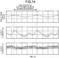
- FIG. 14 is a diagram illustrating a speed true value that is the true value of the rotation speed, the d-axis current, and the q-axis current of the secondary synchronous motor when the two synchronous motors are driven in parallel at low speed in the drive system according to the first embodiment in the presence of output voltage errors equivalent to those of an actual machine.
- FIGS. 13 and 14 illustrate the true value of the rotation speed, the d-axis current, and the q-axis current in that order from the top.
- the horizontal axes represent time.
- FIGS. 13 and 14 illustrate analysis results under the conditions that the difference between the load torques of the two synchronous motors is extremely small, and the angle difference between the magnetic pole positions of the two synchronous motors is close to zero.
- a magnetic flux current compensation method uses the angle difference between the two synchronous motors to change the torque of the secondary synchronous motor 1b.
- the true value of the rotation speed oscillates at the electromechanical spring resonance angular frequency.
- the rotation speed becomes the largest value in each period of the electromechanical spring resonance angular frequency.
- the q-axis current of the secondary synchronous motor 1b also oscillates at the electromechanical spring resonance angular frequency as in the true value of the rotation speed.
- the d-axis current passed to stabilize the drive of the secondary synchronous motor has its compensation direction that needs to be changed depending on whether the angle difference between the two synchronous motors is positive or negative, as described above. Therefore, the d-axis current has a waveform showing the largest value in each period of the electromechanical spring resonance angular frequency as illustrated in the second row from the top of FIGS. 13 and 14 . Under the influence of changes in the sign of the angle difference, thus, the d-axis current contains the pulsation of frequency components that are integral multiples of the electromechanical spring resonance angular frequency. When there are errors in the output voltage of the power inverter 2, pulsating components six times the electrical angular frequency are superimposed on the d- and q-axis currents.
- FIG. 15 is a diagram illustrating speed estimate waveforms when the two synchronous motors are driven in parallel at low speed on the assumption that output voltage errors of the power inverter are zero in the drive system according to the first embodiment.
- the true value of the number of revolutions is indicated by a solid line
- the estimate value of the number of revolutions by the arctangent method is indicated by a dotted line
- the estimate value of the number of revolutions by the adaptive flux observer is indicated by a dashed line.
- the horizontal axis represents time.
- the vertical axis represents the number of revolutions of the rotor of the secondary synchronous motor 1b.
- FIG. 16 is a diagram illustrating speed estimate waveforms when the two synchronous motors are driven in parallel at low speed in the drive system according to the first embodiment in the presence of output voltage errors equivalent to those of an actual machine.
- the true value of the number of revolutions is indicated by a solid line
- the estimate value of the number of revolutions by the arctangent method is indicated by a dotted line
- the estimate value of the number of revolutions by the adaptive flux observer is indicated by a dashed line.
- the horizontal axis represents time.
- the vertical axis represents the number of revolutions of the rotor of the secondary synchronous motor 1b.
- Some fluid utilization apparatuses using a common drive system set the carrier frequency to 10 kHz or higher to reduce electromagnetic noise.
- output voltage errors tend to increase.
- FIG. 15 and FIG. 16 shows that in FIG. 16 , the S/N ratio (Signal to Noise Radio) of the estimated speed waveforms is significantly deteriorated. This tendency is found in speed estimate errors caused by each of the arctangent method and the adaptive flux observer.
- FIG. 17 is a diagram illustrating the results of FFT analysis of the speed estimate waveforms in FIG. 15 .
- FIG. 17 illustrates the true value of the rotation speed, the speed estimate value by the arctangent method, and the speed estimate value by the adaptive flux observer in order from the top.
- the horizontal axes represent frequency. From FIG. 17 , it is clear that as illustrated in a dotted frame B, speed estimate errors occur at the orders of integral multiples of the electromechanical spring resonance angular frequency. The frequencies of these speed estimate errors match the frequencies of the pulsating components of the magnetic flux current that is the d-axis current illustrated in FIG. 13 . Further, as illustrated in a dotted frame A, there are amplitude errors between the true value and the estimate values also at the first-order component of the electromechanical spring resonance angular frequency.
- FIG. 18 is a diagram illustrating the results of FFT analysis of the speed estimate waveforms in FIG. 16 .
- FIG. 18 illustrates the true value of the rotation speed, the speed estimate value by the arctangent method, and the speed estimate value by the adaptive flux observer in order from the top.
- the horizontal axes represent frequency. From FIG. 18 , it is clear that as illustrated in a dotted frame A, there are several times greater errors at the first-order component of the electromechanical spring resonance angular frequency. Further, it is clear that as illustrated in a dotted frame B, extremely large peaks appear at the orders of integral multiples of the electromechanical spring resonance angular frequency. Furthermore, as illustrated in a dotted frame C, it is clear that peaks appear on the high frequency side due to output voltage error components of the power inverter 2.
- Patent Literature 1 when the technique disclosed in Patent Literature 1 is used in a fluid utilization apparatus, a marked phenomenon in which rotation in the low-speed range becomes unstable occurs.
- the load of a fluid utilization apparatus is often a quadratic-torque load, and its load characteristic is a light load on the low-rpm side.
- the quadratic-torque load is a load that allows the load torque to increase in proportion to the square of the rotation speed of the motor.
- the torque current decreases on the low-rpm side, and the compensation accuracy of output voltage errors of the power inverter 2 decreases in a region where the current is small.
- the speed electromotive force of the motor decreases in the low-rpm range.
- the influence of output voltage errors becomes relatively large. Consequently, the speed estimate errors described above increase, making it impossible to accurately determine the speed difference between the two synchronous motors, which leads to a state of unstable control.
- the inventor of the present application has performed various filtering processing on a speed difference signal containing a lot of the speed estimate errors to improve the stability, but has failed to obtain satisfactory performance.
- the inventor of the present application has come to device a technique of calculating the magnetic flux current command from a pulsating component of the torque current of the secondary synchronous motor 1b as he has considered that it is necessary to establish a technique for eliminating the influence of transient speed estimate errors in order to stably drive the two synchronous motors in parallel even where such speed estimate errors exist.
- the S/N ratio of the magnetic flux current command is greatly improved as compared with that of the technique disclosed in Patent Literature 1. The reason is as follows.
- the estimated magnetic pole position signal has high-frequency components of errors in the estimated speed removed by integration processing in the calculation process.
- an error signal caused by a change in the magnetic flux current command remains, but its error falls within several degrees.
- the torque current of the secondary synchronous motor 1b can be determined with relatively high accuracy even when the magnetic flux current is changed.
- steady position estimation errors may occur due to the influence of variations in motor constant, such errors are DC component estimation errors, and thus do not become a problem when a pulsating component is extracted by the pulsating component extraction unit 7.
- a mechanical system may have a large moment of inertia. In this case, even when torque pulsation is so large that the inverter stops due to overcurrent, a pulsating component appearing in a speed signal may be very small. In this case, it is better to perform stabilizing compensation when the pulsation of torque current has increased to some extent, instead of performing stabilization after speed pulsation has become so large that speed pulsation can be observed. In this case, a torque current signal has a better S/N ratio than an estimated speed signal, and thus it can be said that it is better to use the torque current signal for stabilizing compensation.
- the magnetic flux current command determination unit 9 determines the magnetic flux current command on the basis of a pulsating component of the torque current flowing to the secondary synchronous motor 1b.
- FIG. 19 is a diagram illustrating a configuration example of the magnetic flux current command determination unit illustrated in FIG. 1 .
- FIG. 20 is a first diagram for explaining sign determination processing performed by a sign determiner illustrated in FIG. 19 .
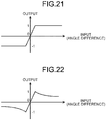
- FIG. 21 is a second diagram for explaining the sign determination processing performed by the sign determiner illustrated in FIG. 19 .
- FIG. 22 is a third diagram for explaining the sign determination processing performed by the sign determiner illustrated in FIG. 19 .
- the magnetic flux current command determination unit 9 illustrated in FIG. 19 includes a pulsation suppression control unit 91 and a compensation direction determination unit 92.
- the magnetic flux current command determination unit 9 receives a pulsating component of the torque current of the secondary synchronous motor 1b, and determines the magnetic flux current command, using the pulsation suppression control unit 91 and the compensation direction determination unit 92.
- the pulsation suppression control unit 91 includes a gain multiplication unit 911 and a phase adjustment unit 912.
- the gain multiplication unit 911 adjusts gain of the torque current pulsating component that is the input signal.
- the phase adjustment unit 912 adjusts the phase of the torque current pulsating component that is the input signal, and outputs the pulsating component whose amplitude has been adjusted. If the stability of the system can be provided by only one of the gain multiplication unit 911 and the phase adjustment unit 912, the pulsation suppression control unit 91 does not necessarily need to include both the gain multiplication unit 911 and the phase adjustment unit 912.
- the gain multiplication unit 911 has a role of adjusting the stability and responsiveness of the system as the gain multiplication unit 911 multiplies the torque current pulsating component that is the input signal, by a specific gain and outputs the result of the multiplication.
- the gain may be changed in accordance with operating conditions. For example, the gain may be increased in the low-speed range, and the gain may be reduced in the high-speed range.
- the phase adjustment unit 912 is formed, for example, by a phase lag compensator, a low-pass filter, an integrating controller, or the like. Phase lag compensators reduce gain by a certain value in the high-frequency range for stabilization, and are commonly used in industry. Low-pass filters and integrating controllers also have a property of changing a signal phase in the high-frequency range. Thus, a low-pass filter or an integrating controller can be used like a phase lag compensator.
- a cutoff angular frequency of the approximate integrator is preferably set to 1/3 or lower the electromechanical spring resonance angular frequency. If possible, the cutoff angular frequency is set to a value of 1/10 to 1/20 the electromechanical spring resonance angular frequency. With this setting, the phase can be delayed by about 90 degrees in the vicinity of the electromechanical spring resonance angular frequency, enhancing control stability.
- a dead zone may be provided at either the input or output of the pulsation suppression control unit 91.
- the dead zone is useful for removing frequency components other than the electromechanical spring resonance which have not been able to be completely removed by the pulsating component extraction unit 7 described above.
- the compensation direction determination unit 92 includes a sign determiner 921 and a multiplier 922. In accordance with the operation principle described with reference to FIGS. 5 to 11 , the compensation direction determination unit 92 determines the direction of compensation of the magnetic flux current command from the angle difference between the magnetic pole positions of the rotors of the two synchronous motors.
- the sign determiner 921 performs the sign determination processing illustrated in FIGS. 20 to 22 .
- the horizontal axes in FIGS. 20 to 22 represent the angle difference that is the input of the sign determiner 921.
- the angle difference has a positive or negative value as illustrated in FIG. 11 .
- the vertical axes in FIGS. 20 to 22 represent the value of output of the sign determiner 921.
- the most basic sign determination processing is a method illustrated in FIG. 20 .
- the sign determiner 921 outputs "1" when the angle difference is positive, and outputs "-1" when the angle difference is negative.
- chattering may occur when the angle difference is close to zero. Therefore, as in FIG. 21 , in a region where the angle difference is close to zero, the output of the sign determiner 921 may be gradually switched from “1" to "-1", or the output of the sign determiner 921 may be gradually switched from "-1" to "1".
- the influence of the change amount of the magnetic flux current of the main synchronous motor 1a on the change amount of the torque of the secondary synchronous motor 1b is greater than that under conditions where the angle difference is small. Therefore, as in FIG. 22 , in a region where the angle difference is large, the output value of the sign determiner 921 may be gradually reduced as the angle difference increases.
- the multiplier 922 multiplies the output of the sign determiner 921 by the output of the pulsation suppression control unit 91 to thereby generate the magnetic flux current command. That is, the magnetic flux current command determination unit 9 determines the magnetic flux current command, from the pulsating component suppressed by the pulsation suppression control unit 91 and the compensation direction determined by the sign determiner 921 of the compensation direction determination unit 92.
- the effect of using the magnetic flux current command generated in this way is as follows.
- Patent Literature 1 For the drive system employing the position sensorless control, as described above so far, transient speed estimate errors occur due to a change in the magnetic flux current command at the time of low-speed drive.
- the method of stabilizing the drive of the secondary synchronous motor 1b using the speed difference as disclosed in Patent Literature 1 is directly affected by speed estimate errors, which results in an unstable control state, causing various problems such as increases in noise and vibration and a decrease in motor efficiency. For this reason, Patent Literature 1 encounters a problem of necessity of increasing the lower limit of the number of revolutions as compared with an existing synchronous motor drive system including a single power inverter that drive a single synchronous motor. Therefore, it is difficult to replace an existing synchronous motor drive system with a parallel drive system using the technique disclosed in Patent Literature 1.
- the drive system 100 determines the magnetic flux current command, using the pulsating component of the torque current of the secondary synchronous motor 1b and the angle difference between the magnetic pole positions of the two synchronous motors. Consequently, the magnetic flux current command is improved in S/N ratio, and is less likely to be affected by speed estimate errors. As a result, problems such as increases in noise and vibration, a decrease in motor efficiency, and a loss of synchronism are solved. Further, since the stability at the time of low-speed drive is improved, the lower limit of the number of revolutions can be kept at a value equivalent to that of existing synchronous motor drive systems that drive a single synchronous motor with a single power inverter. This facilitates replacement of an existing synchronous motor drive system with the drive system 100 according to the first embodiment.
- a second embodiment described below provides a configuration example in which a magnetic flux current is determined using a pulsating component of active power consumed by the secondary synchronous motor 1b.
- a magnetic flux current is determined using a pulsating component of active power consumed by the secondary synchronous motor 1b.
- One method for that purpose is the method using the pulsating component of the torque current described in the first embodiment.
- the magnetic flux current may be determined using the pulsating component of the active power instead of the pulsating component of the torque current.
- the moment of inertia of mechanical systems may be large. In this case, it is better to observe the pulsating component of the active power rather than observe the estimated speed signal.
- FIG. 23 is a diagram illustrating a configuration of a drive system according to the second embodiment of the present invention.
- a drive system 100A according to the second embodiment includes a pulsating component extraction unit 70A in place of the pulsating component extraction unit 70 illustrated in FIG. 1 .
- the pulsating component extraction unit 70A includes a secondary active power pulsating component extraction unit 10.
- the other components are the same as or equivalent to those of the first embodiment.
- the same reference numerals are assigned to the same or equivalent components without duplicated explanations.
- Active power P x can be determined by formula (18) below using three-phase voltage commands v u *, v v *, and v w * and phase currents i u *, i v *, and i w *. Subscripts " x " are for distinguishing between the main one and the secondary one.
- R a is the armature resistance.
- the three-phase voltage commands v u *, v v *, and v w * are obtained from the current control unit 6.
- the phase currents i u *, i v *, and i w * are obtained from the current detection unit 4b.
- the second term on the right side of formula (18) above represents copper loss due to the armature resistance. Strictly speaking, the copper loss is also part of the active power, but it is preferable to subtract the copper loss because required information corresponds to the torque pulsation of the secondary synchronous motor 1b.
- the armature resistance may be small enough to be negligible in which case only the first term on the right side may be calculated.
- the secondary active power pulsating component extraction unit 10 performs arithmetic processing similar to that of the secondary torque current pulsating component extraction unit 7 described in the first embodiment, to extract a pulsating component from the active power of the secondary synchronous motor 1b. Determining the magnetic flux current command using this information can provide the same effects as those of the first embodiment.
- the magnetic flux current command determination unit 9 of the second embodiment includes the pulsation suppression control unit 91 including the gain multiplication unit 911 and the phase adjustment unit 912 as in the first embodiment
- the gain multiplication unit 911 of the second embodiment adjusts gain of the active power pulsating component that is the input signal
- the phase adjustment unit 912 of the second embodiment adjusts the phase of the active power pulsating component that is the input signal.
- the pulsation suppression control unit 91 of the second embodiment does not necessarily need to include both the gain multiplication unit 911 and the phase adjustment unit 912.
- the second embodiment is useful when the moment of inertia of the loads connected to the synchronous motors is large. Also, the second embodiment, which does not use the coordinate transformation operation, provides a small amount of calculation as compared with the first embodiment and thus is useful when an arithmetic device of a simple configuration is used. Specifically, the secondary torque current pulsating component extraction unit 7 of the first embodiment transforms the coordinates of the currents in the three-phase coordinate system detected by the current detection unit 4b into the rotating rectangular coordinate system, using the signal from the magnetic pole position estimation unit 5b, determines the torque current, and extracts the pulsating component of the torque current.
- the secondary active power pulsating component extraction unit 10 determines the active power, using the currents in the three-phase coordinate system detected by the current detection unit 4b as they are, and extracts the pulsating component of the active power, as shown in formula (18) above. Then, the magnetic flux current command determination unit 9 of the second embodiment can determine the magnetic flux current command, using the pulsating component.
- the second embodiment eliminates the need for coordinate transformation, reducing the amount of calculation. In applications where the moment of inertia is large, observing the pulsating component of the active power as described above reduces the coordinate transformation by onetime. Thus, the second embodiment can reduce calculation load.
- FIG. 24 is a diagram illustrating a configuration of a drive system according to a third embodiment of the present invention.
- a drive system 100B according to the third embodiment includes a pulsating component extraction unit 70B in place of the pulsating component extraction unit 70 illustrated in FIG. 1 .
- the pulsating component extraction unit 70B includes the secondary torque current pulsating component extraction unit 7, a main torque current pulsating component extraction unit 11, and a subtracter 8a that is a second subtracter.
- the other components are the same as or equivalent to those of the first embodiment.
- the same reference numerals are assigned to the same or equivalent components without duplicated explanations.
- the third embodiment described below provides a configuration example in which the magnetic flux current command is determined from the difference between the pulsating component of the torque current of the secondary synchronous motor 1b and the pulsating component of the torque current of the main synchronous motor 1a.
- the drive systems 100 and 100A of the first and second embodiments are configured on the assumption that the pulsating component of the torque current of the main synchronous motor 1a is minute in a steady state. Since the main synchronous motor 1a is vector-controlled, if the torque current command value is a constant value, the torque current of the main synchronous motor 1a should follow the command value. However, in fact, the torque current of the main synchronous motor 1a pulsates due to various disturbance factors.
- Possible disturbance factors include a time during which to prevent short-circuiting of the semiconductor devices of the series-connected upper and lower arms of the power inverter 2, offset of current sensors, gain imbalance of current sensors, distortion of magnetic flux produced from the magnets provided to the rotor, etc. Torque current pulsation due to these factors occurs in the secondary synchronous motor 1b alike. In the first and second embodiments, if some AC component is superimposed on the torque current command, this also becomes a disturbance to the magnetic flux current command determination unit 9. A disturbance component superimposed on the torque current command causes torque current pulsation of that frequency also in the secondary synchronous motor 1b. Since such a disturbance component is produced by other than self-oscillation due to electromechanical spring resonance, it is not appropriate to feed that disturbance component back to the magnetic flux current command determination unit.
- the secondary torque current pulsating component extraction unit 7 of the first embodiment and the main torque current pulsating component extraction unit 11 of the third embodiment are formed by a high-pass filter, a bandpass filter, or the like.
- a high-pass filter has poor disturbance removal characteristics.
- measurement of the electromechanical spring resonance angular frequency is required in order to improve disturbance removal characteristics.
- the third embodiment is configured to subtract the pulsating component of the torque current generated in the main synchronous motor 1a from the pulsating component of the torque current of the secondary synchronous motor 1b.
- the drive system 100B includes the main torque current pulsating component extraction unit 11 in addition to the secondary torque current pulsating component extraction unit 7. Further, the drive system 100B includes the subtracter 8a that determines the difference between the torque current pulsating component from the secondary torque current pulsating component extraction unit 7 and the torque current pulsating component from the main torque current pulsating component extraction unit 11.
- the main torque current pulsating component extraction unit 11 calculates the pulsating component of the torque current of the main synchronous motor 1a.
- the calculation method may be a method similar to that of the secondary torque current pulsating component extraction unit 7 described in the first embodiment.
- the subtracter 8a calculates the difference between the pulsating components of the torque currents generated in the two synchronous motors.
- the magnetic flux current command determination unit 9 determines the magnetic flux current command, using the difference.
- the third embodiment described above provides the method of using the difference between the pulsating components of the torque currents generated in the two synchronous motors, the difference between the pulsating components of the active power may be used instead as a matter of course.
- the drive system 100B of the third embodiment may be configured such that one of the secondary torque current pulsating component extraction unit 7 and the main torque current pulsating component extraction unit 11 calculates the pulsation of the torque current, and the other calculates the pulsation of the active power, and then these pulsations are converted on the same scale to determine the difference therebetween.
- FIG. 25 is a configuration diagram of a fluid utilization apparatus according to the fourth embodiment of the present invention.
- the fourth embodiment provides a fluid utilization apparatus 300 including a propeller fan 300a provided on the rotating shaft of the main synchronous motor 1a, and a propeller fan 300b provided on the rotating shaft of the secondary synchronous motor 1b.
- the fluid utilization apparatus 300 illustrated in FIG. 25 includes the drive system 100 of the first embodiment, and the drive system 100 includes a power inverter drive 200.
- the power inverter drive 200 includes a processor 201 and memory 202.
- the functions illustrated in FIG. 1 that is, the functions of the current control unit 6, the magnetic pole position estimation units 5a and 5b, the secondary torque current pulsating component extraction unit 7, the subtracter 8, and the magnetic flux current command determination unit 9 are implemented using the processor 201 and the memory 202.
- each of the above-described functions is implemented by software, firmware, or a combination of them.
- the software or firmware is described as programs and stored in the memory 202.
- the processor 201 reads and executes the programs stored in the memory 202. These programs can be said to cause a computer to execute procedures and methods executed by the above-described functions.
- the memory 202 corresponds to semiconductor memory such as Random Access Memory (RAM), Read Only Memory (ROM), a flash memory, an Erasable Programmable Read Only Memory (EPROM), or an Electrically Erasable Programmable Read Only Memory (EEPROM) (registered trademarks).
- RAM Random Access Memory
- ROM Read Only Memory
- EPROM Erasable Programmable Read Only Memory
- EEPROM Electrically Erasable Programmable Read Only Memory
- the semiconductor memory may be nonvolatile memory or volatile memory.
- the memory 202 corresponds to a magnetic disk, a flexible disk, an optical disk, a compact disk, a mini disk, or a Digital Versatile Disc (DVD).
- the processor 201 may output or store data such as calculation results to or in the memory 202, or may store the data in an auxiliary storage device (not illustrated) via the memory 202.
- the fluid utilization apparatus 300 may include the drive system 100A of the second embodiment or the drive system 100B of the third embodiment.
- the functions of the current control unit 6, the magnetic pole position estimation units 5a and 5b, the secondary active power pulsating component extraction unit 10, the subtracter 8, and the magnetic flux current command determination unit 9 illustrated in FIG. 23 are implemented using the processor 201 and the memory 202.
- the functions of the current control unit 6, the magnetic pole position estimation units 5a and 5b, the secondary torque current pulsating component extraction unit 7, the main torque current pulsating component extraction unit 11, the subtracter 8, the subtracter 8a, and the magnetic flux current command determination unit 9 illustrated in FIG. 24 are implemented using the processor 201 and the memory 202.
- the power inverter 2 may basically have any circuit configuration that can supply desired AC power to the main synchronous motor 1a and the secondary synchronous motor 1b. Information on the currents detected by the current detection units 4a and 4b is transmitted to the processor 201.
- the two propeller fans 300a and 300b may be of the same shape or of different shapes. Air flow paths of the two propeller fans 300a and 300b do not necessarily need to be the same.
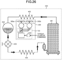
- the fluid utilization apparatus 300 is an air conditioner
- the two propeller fans 300a and 300b correspond to two blowing fans provided in a blowing chamber in an outdoor unit of the air conditioner, and the air flow paths correspond to the blowing chamber.
- the blowing chamber is a space formed by being surrounded by side plates, a ceiling plate, a bottom plate, a heat exchanger, and others of the outdoor unit. In the blowing chamber, flows of air are formed by the rotation of the propeller fans 300a and 300b.
- the two synchronous motors may be provided with fans of different shapes.
- the cross-sectional area of the flow path in which one fan is provided may be made smaller than the cross-sectional area of the flow path in which the other fan is provided.
- a fluid utilization apparatus with different specifications may be driven in which, for example, a propeller fan is driven by one synchronous motor, and a pump is driven by the other synchronous motor.
- the fluid utilization apparatus 300 may include a voltage detection unit that detects voltage output by the power inverter 2 so that voltage information detected by the voltage detection unit is input to the processor 201.
- the fluid utilization apparatus 300 may include an air velocity sensor that measures the air velocity of the fans so that air velocity information detected by the air velocity sensor is input to the processor 201.
- a temperature sensor that detects the temperature of an object cooled by the fans may be provided so that temperature information detected by the temperature sensor is input to the processor 201.
- the fluid load of the fluid utilization apparatus 300 has a damper property.
- the damper property stabilizes the synchronous motor driven in the open loop.
- the damper property becomes weak, and the drive of the synchronous motor becomes unstable. Therefore, the fluid utilization apparatus 300 uses the parallel drive method described in the first, second, or third embodiment. Consequently, the fourth embodiment achieves parallel drive of the synchronous motors in a wide speed range. Further, the fourth embodiment does not need advanced torque control.
- modifying an existing synchronous motor drive system including a single power inverter that drives a single synchronous motor can provide the fluid utilization apparatus 300 that can drive the two propeller fans 300a and 300b and prevent an increase in cost as well.
- a fifth embodiment describes a configuration example of an air conditioner using the fluid utilization apparatus 300 according to the fourth embodiment.
- FIG. 26 is a configuration diagram of an air conditioner according to the fifth embodiment of the present invention.
- An air conditioner 400 according to the fifth embodiment includes the fluid utilization apparatus 300, a refrigerant compressor 401, a condenser 403, a receiver 404, an expansion valve 405, and an evaporator 406.
- the refrigerant compressor 401 and the condenser 403 are connected by piping.
- the condenser 403 and the receiver 404 are connected by piping
- the receiver 404 and the expansion valve 405 are connected by piping
- the expansion valve 405 and the evaporator 406 are connected by piping
- the evaporator 406 and the refrigerant compressor 401 are connected by piping. Consequently, a refrigerant circulates through the refrigerant compressor 401, the condenser 403, the receiver 404, the expansion valve 405, and the evaporator 406.
- the fluid utilization apparatus 300 includes the current detection units 4a and 4b, the magnetic pole position estimation units 5a and 5c, and others illustrated in FIG. 1 and other drawings.
- the air conditioner 400 repeatedly perform process steps of refrigerant evaporation, compression, condensation, and expansion.
- the refrigerant changes from liquid to gas, and further changes from gas to liquid, so that heat exchange is performed between the refrigerant and the air outside the machine.
- the evaporator 406 has a cooling function of evaporating the refrigerant liquid under low pressure conditions and taking heat from the air around the evaporator 406.
- the refrigerant compressor 401 compresses the refrigerant gas gasified by the evaporator 406, condensing the refrigerant into a high-pressure gas.
- the condenser 403 releases heat of the refrigerant gas that has raised to a high temperature in the refrigerant compressor 401, condensing the high-pressure refrigerant gas into a refrigerant liquid.
- the fluid utilization apparatus 300 generates currents of air by rotating the propeller fans 300a and 300b, and passes the currents of air through the condenser 403, thereby cooling the condenser 403.
- the expansion valve 405 throttles and expands the refrigerant liquid to evaporate the refrigerant, and converts the refrigerant liquid into a low-pressure liquid.
- the receiver 404 is provided for adjusting the amount of the circulating refrigerant, and may be omitted in a small apparatus.
- the condenser 403 becomes larger as the air conditioner 400 has greater output power, it becomes necessary to increase the cooling performance of the fluid utilization apparatus 300 that functions as a cooling apparatus for cooling the condenser 403.
- the large-size air conditioner 400 uses the fluid utilization apparatus 300 including a plurality of cooling fans to improve the cooling performance.
- a parallel drive system using the technique disclosed in Patent Literature 1 is excellent in cost, but poses a problem of the unstable drive in the low-rpm range if such a system is configured with position sensorless control.
- the carrier frequency is often set high to 10 kHz or higher.
- output voltage errors increase, and the drive in the low-rpm range tends to be unstable.
- the air conditioner 400 uses a parallel drive system using the technique disclosed in Patent Literature 1
- a problem of the drive operating range of the air conditioner 400 being narrowed arises.
- the air conditioner 400 according to the fifth embodiment which uses the parallel drive methods described in the first to third embodiments, does not become unstable in low-speed-range drive, and can increase a drivable range. Further, the parallel drive methods described in the first to third embodiments are based on position sensorless control, and thus can reduce the manufacturing cost of the air conditioner 400 as compared with a case where position sensors are used. Accordingly, the drive systems 100, 100A, and 100B according to the first to third embodiments can achieve both cost reduction and high cooling performance required of the cooling fans for the air conditioner 400.
Landscapes
- Engineering & Computer Science (AREA)
- Power Engineering (AREA)
- Control Of Ac Motors In General (AREA)
- Control Of Multiple Motors (AREA)
Abstract
Description
- The present invention relates to a drive system that drives two synchronous motors connected in parallel to a single power inverter, a fluid utilization apparatus including the drive system, and an air conditioner including the fluid utilization apparatus.
- A synchronous motor may fail to produce proper torque, and thus lose synchronism or stop its operation unless information on a rotor position that is a rotational position of a rotor is used to apply a proper voltage in accordance with the rotational position. In driving a plurality of synchronous motors, thus, the prior art have used the same number of power inverters as the number of synchronous motors to apply a voltage according to a rotational position of a rotor of each of the synchronous motors. Unfortunately, this configuration poses a problem of increased cost because the number of power inverters increases as the number of synchronous motors increases. In recent years, the sophistication of synchronous motor control technology have made attempts to drive two synchronous motors with a single power inverter.
- According to a technique disclosed in
Patent Literature 1, two synchronous motors, which are a main synchronous motor and a secondary synchronous motor, are connected to a single power inverter. A drive system controls those two synchronous motors, using rotation speeds of the two synchronous motors. For the technique described inPatent Literature 1, the drive system performs vector control on the main synchronous motor, and uses both a difference in rotation speed and a difference in rotation position between the two synchronous motors to determine a d-axis current command for the main synchronous motor, such that the drive of the secondary synchronous motor is stabilized. Vector control is a control method in which currents flowing through a synchronous motor are decomposed into a current component generating torque and a current component generating magnetic flux, and the current components are controlled independently. - Patent Literature 1:
US 2015/0,229,245 A Non Patent Literature - Non Patent Literature 1: Yongjae Lee, Jung-Ik Ha, "Analysis and Control of Mono Inverter Dual Parallel SPMSM Drive System", 2014, IEEE
- Non Patent Literature 2: Yongjae Lee, Jung-Ik Ha, "Control Method for Mono Inverter Dual Parallel Surface-Mounted Permanent-Magnet Synchronous Machine Drive System", 2015, IEEE
-
Patent Literature 1 teaches that the technique disclosed inPatent Literature 1 is applicable to position sensorless control that does not use sensors such as speed detection means and position detection means.Non Patent Literatures Patent Literature 1. Typically, position sensorless control is problematic from the standpoint of operation stability in the low-speed range. Such a problem with position sensorless control is that the low-rpm range provides a decreased speed electromotive force of motors, and the influence of output voltage errors of the power inverter becomes relatively large. Since the operation stability at low speed is an issue even when a single synchronous motor is driven by a single power inverter, it is more difficult to provide the operation stability in the low-speed range when two synchronous motors are driven in parallel by a single power inverter. Unfortunately,Patent Literature 1,Non Patent Literature 1, andNon Patent Literature 2 do not specifically describe a drive method in the low-speed range. - The present invention has been made in view of the above. It is an object of the present invention to provide a drive system that can prevent unstable rotation in the low-speed range even when two synchronous motors are driven in position sensorless control manner, using a single power inverter.
- In order to solve the above-described problem and achieve the object, a drive system of the present invention comprises a power inverter to supply power to a first synchronous motor and a second synchronous motor connected in parallel to each other; a first current detector to detect a first current flowing to the first synchronous motor; and a second current detector to detect a second current flowing to the second synchronous motor. The drive system also comprises a first magnetic pole position estimation unit to estimate a first magnetic pole position of a rotor of the first synchronous motor, using a voltage command for driving the first synchronous motor and the first current, and a second magnetic pole position estimation unit to estimate a second magnetic pole position of a rotor of the second synchronous motor, using the voltage command and the second current. The drive system further comprises a control unit to output the voltage command, using a torque current command, a magnetic flux current command, the first current, and the first magnetic pole position, and a pulsating component extraction unit to extract at least one of a torque current pulsating component and an active power pulsating component, the torque current pulsating component being contained in a torque current flowing to the second synchronous motor, the active power pulsating component contained in active power consumed by the second synchronous motor. The drive system further comprises a first subtracter to determine an angle difference that is a difference between the magnetic pole positions of the rotors of the first synchronous motor and the second synchronous motor, using the first magnetic pole position and the second magnetic pole position, and a magnetic flux current command determination unit to determine the magnetic flux current command, using the pulsating component extracted by the pulsating component extraction unit and the angle difference.
- The present invention has the advantage of preventing the unstable rotation in the low-speed range even when the two synchronous motors are driven in the position sensorless control manner, using the single power inverter.
-
-
FIG. 1 is a diagram illustrating a configuration of a drive system according to a first embodiment of the present invention. -
FIG. 2 is a diagram illustrating a first configuration example of a secondary torque current pulsating component extraction unit illustrated inFIG. 1 . -
FIG. 3 is a diagram illustrating a second configuration example of the secondary torque current pulsating component extraction unit illustrated inFIG. 1 . -
FIG. 4 is a diagram illustrating a third configuration example of the secondary torque current pulsating component extraction unit illustrated inFIG. 1 . -
FIG. 5 is a first diagram for explaining the torque change behavior of a secondary synchronous motor illustrated inFIG. 1 . -
FIG. 6 is a second diagram for explaining the torque change behavior of the secondary synchronous motor illustrated inFIG. 1 . -
FIG. 7 is a third diagram for explaining the torque change behavior of the secondary synchronous motor illustrated inFIG. 1 . -
FIG. 8 is a fourth diagram for explaining the torque change behavior of the secondary synchronous motor illustrated inFIG. 1 . -
FIG. 9 is a fifth diagram for explaining the torque change behavior of the secondary synchronous motor illustrated inFIG. 1 . -
FIG. 10 is a sixth diagram for explaining the torque change behavior of the secondary synchronous motor illustrated inFIG. 1 . -
FIG. 11 is a diagram illustrating a main d-axis current, the sign of angle difference, and the states of torque of the secondary synchronous motor illustrated inFIGS. 6 ,7 ,9, and 10 in association with each other. -
FIG. 12 is a diagram illustrating an example in which magnetic pole position estimation units illustrated inFIG. 1 are each formed by an adaptive flux observer. -
FIG. 13 is a diagram illustrating a speed true value that is the true value of the rotation speed, a d-axis current, and a q-axis current of the secondary synchronous motor when two synchronous motors are driven in parallel at low speed on the assumption that output voltage errors of a power inverter are zero, in the drive system according to the first embodiment. -
FIG. 14 is a diagram illustrating a speed true value that is the true value of the rotation speed, a d-axis current, and a q-axis current of the secondary synchronous motor when the two synchronous motors are driven in parallel at low speed with output voltage errors equivalent to those of an actual machine added, in the drive system according to the first embodiment. -
FIG. 15 is a diagram illustrating speed estimate waveforms when the two synchronous motors are driven in parallel at low speed on the assumption that output voltage errors of the power inverter are zero, in the drive system according to the first embodiment. -
FIG. 16 is a diagram illustrating speed estimate waveforms when the two synchronous motors are driven in parallel at low speed in the drive system according to the first embodiment in the presence of output voltage errors equivalent to those of an actual machine added. -
FIG. 17 is a diagram illustrating the results of fast Fourier transform (FFT) analysis of the speed estimate waveforms inFIG. 15 . -
FIG. 18 is a diagram illustrating the results of FFT analysis of the speed estimate waveforms inFIG. 16 . -
FIG. 19 is a diagram illustrating a configuration example of a magnetic flux current command determination unit illustrated inFIG. 1 . -
FIG. 20 is a first diagram for explaining sign determination processing performed by a sign determiner illustrated inFIG. 19 . -
FIG. 21 is a second diagram for explaining the sign determination processing performed by the sign determiner illustrated inFIG. 19 . -
FIG. 22 is a third diagram for explaining the sign determination processing performed by the sign determiner illustrated inFIG. 19 . -
FIG. 23 is a diagram illustrating a configuration of a drive system according to a second embodiment of the present invention. -
FIG. 24 is a diagram illustrating a configuration of a drive system according to a third embodiment of the present invention. -
FIG. 25 is a configuration diagram of a fluid utilization apparatus according to a fourth embodiment of the present invention. -
FIG. 26 is a configuration diagram of an air conditioner according to a fifth embodiment of the present invention. - Hereinafter, a drive system, a fluid utilization apparatus, and an air conditioner according to embodiments of the present invention will be described in detail with reference to the drawings. The embodiments are not intended to limit the invention.
-
FIG. 1 is a diagram illustrating a configuration of a drive system according to a first embodiment of the present invention. Synchronous motors are broadly divided into permanent magnet field synchronous motors in which permanent magnets are provided to the rotor, winding field synchronous motors in which field windings are wound on the rotor, and reluctance synchronous motors that obtain running torque using the saliency of the rotor. Of these types of synchronous motors, synchronous motors of the same type, for example, two permanent magnet field synchronous motors are connected in parallel to adrive system 100 according to the first embodiment. In the first embodiment, one of the two synchronous motors is referred to as a mainsynchronous motor 1a, and the other is referred to as a secondarysynchronous motor 1b. The mainsynchronous motor 1a is a first synchronous motor, and the secondarysynchronous motor 1b is a second synchronous motor. - Although three-phase permanent magnet field synchronous motors are used in the first embodiment, it is only necessary that the two synchronous motors have nearly equal motor constants. Synchronous motors other than permanent magnet field ones may be used, or synchronous motors with phases other than three phases such as two phases or five phases may be used.
- The
drive system 100 includes apower inverter 2, acurrent detection unit 4a, acurrent detection unit 4b, and a magnetic poleposition estimation unit 5a. Thepower inverter 2 supplies power to the mainsynchronous motor 1a and the secondarysynchronous motor 1b connected in parallel to the mainsynchronous motor 1a. Thecurrent detection unit 4a detects a first current flowing to the mainsynchronous motor 1a. Thecurrent detection unit 4b detects a second current flowing to the secondarysynchronous motor 1b. The magnetic poleposition estimation unit 5a is a first magnetic pole position estimation unit. Thedrive system 100 further includes a magnetic poleposition estimation unit 5b, a current control unit 6, a pulsatingcomponent extraction unit 70, asubtracter 8, and a magnetic flux currentcommand determination unit 9. The magnetic poleposition estimation unit 5b is a second magnetic pole position estimation unit. The current control unit 6 is a control unit for outputting a voltage command. Thesubtracter 8 is a first subtracter. The pulsatingcomponent extraction unit 70 includes a secondary torque current pulsating component extraction unit 7. In the following, the secondary torque current pulsating component extraction unit 7 is sometimes simply referred to as the "pulsating component extraction unit 7". - The
power inverter 2 converts DC power supplied from aDC voltage source 3 into AC power, and outputs the AC power to the mainsynchronous motor 1a and the secondarysynchronous motor 1b. In the first embodiment, a voltage source inverter is used as thepower inverter 2. The voltage source inverter is a device that switches a DC voltage supplied from theDC voltage source 3, such that the DC voltage is converted into an AC voltage. Thepower inverter 2 is not limited to the voltage source inverter, and may be a circuit such as a current source inverter, a matrix converter that converts AC power into AC power different in amplitude and frequency, or a multi-level inverter in which the outputs of a plurality of inverters are connected in series or in parallel, as long as it can output AC power for driving the mainsynchronous motor 1a and the secondarysynchronous motor 1b. - The
current detection unit 4a that is a first current detector detects phase currents flowing from thepower inverter 2 to the mainsynchronous motor 1a, and outputs current information indicating the values of the detected phase currents. Thecurrent detection unit 4b that is a second current detector detects phase currents flowing from thepower inverter 2 to the secondarysynchronous motor 1b, and outputs current information indicating the values of the detected phase currents. - The
current detection units current detection units drive system 100 according to the first embodiment, currents are detected by thecurrent detection units FIG. 1 , phase currents flowing to the synchronous motors are directly detected, a current detection method is not limited to the example of direct detection. Any method may be used in which currents flowing to the synchronous motors can be calculated by Kirchhoff's current law. For example, a single-shunt current detection method using a shunt resistor provided in a negative DC bus of thepower inverter 2, a lower-arm shunt current detection method using shunt resistors connected in series with lower arms of thepower inverter 2, or the like may be used to detect phase currents flowing to the synchronous motors. For the three-phase power inverter 2, the lower-arm shunt current detection method uses shunt resistors connected in series with three lower arms, and thus is also called a three-shunt current detection method. However, in the single-shunt current detection method or the three-shunt current detection method, only the total value of currents flowing to the mainsynchronous motor 1a and the secondarysynchronous motor 1b is measured. Thus, it is necessary to provide current sensors near one synchronous motor of the mainsynchronous motor 1a and the secondarysynchronous motor 1b. Needless to say, for a three-phase synchronous motor, if current sensors are provided to wires of any two phases of wires of three phases connected to the synchronous motor, a current of the remaining one phase can be calculated by Kirchhoff's current law. Thus, it is not necessary to provide a current sensor to each of the wires of three phases. For the configuration and arrangement of thecurrent detection unit 4a and thecurrent detection unit 4b, various methods are possible. Basically, any method may be used. - Using the first current and a voltage command output, the magnetic pole
position estimation unit 5a estimates a first magnetic pole position of the mainsynchronous motor 1a. The first current, which is detected by thecurrent detection unit 4a, is the phase currents flowing to the mainsynchronous motor 1a. The voltage command is output from the current control unit 6. - Using the second current and the voltage command output, the magnetic pole
position estimation unit 5b estimates a second magnetic pole position of the secondarysynchronous motor 1b. The second current, which is detected by thecurrent detection unit 4b, is the phase currents flowing to the secondarysynchronous motor 1b. The voltage command is output from the current control unit 6. - There are various methods for estimating a magnetic pole position. In the middle- and high-speed range in the entire rotation speed range of the rotor of a synchronous motor, information indicating the speed electromotive force of the synchronous motor is commonly used to determine the magnetic pole position. The speed electromotive force, which is an induced power produced inside the synchronous motor by the rotation of the rotor, is proportional to a field produced between the rotor and the stator of the synchronous motor and the rotation speed of the rotor. Details of the methods of estimating the magnetic pole positions will be described later.
- The current control unit 6 is a vector controller that controls a current flowing to the main
synchronous motor 1a, by performing vector control for coordinate transformation of the current detected by thecurrent detection unit 4a into a current command value in a d-q coordinate system where the d-axis is the direction of magnetic flux produced by the permanent magnets of the rotor of the mainsynchronous motor 1a, and the q-axis is an axis orthogonal to the d-axis. Common vector controllers control a current on d and q coordinates based on the magnetic poles of the rotor. This is because transformation of phase currents into values on d and q coordinates changes an AC amount into a DC amount, thereby facilitating the control. For a synchronous motor, a q-axis current is proportional to the magnet torque of the synchronous motor, and thus the q-axis is referred to as a torque axis, and the q-axis current is referred to as a torque current. In contrast to the q-axis current, a d-axis current, which causes a change in magnetic flux produced at the stator, changes the amplitude of the output voltage of the synchronous motor. For this reason, the d-axis is referred to as a magnetic flux axis, and the d-axis current is referred to as a magnetic flux current, an exciting current, or the like. Types of synchronous motors include surface magnet synchronous AC motors in which permanent magnets are provided on the outer peripheral surface of the rotor core, permanent magnet embedded motors in which permanent magnets are embedded inside the rotor core, etc. For a permanent magnet embedded motor, a d-axis current changes reluctance torque, and thus it is not only a q-axis current that acts on torque. Generally, however, the q-axis current is often referred to as a torque current. - The coordinate transformation uses an estimate value of the magnetic pole position calculated by the magnetic pole
position estimation unit 5a. The current control unit 6 may use a polar coordinate system, not the d-q coordinate system in vector control. Such a polar coordinate system is, for example, an α-β stator coordinate system or a γ-δ coordinate system. Further, the current control unit 6 may employ direct torque control (DTC) instead of vector control. However, if DTC is employed, it is necessary to convert a current command into a magnetic flux command and a torque command. - The torque current and the magnetic flux current can be more precisely calculated by the control performed in a coordinate system based on magnetic flux produced from the stator rather than in the d-q coordinate system. This coordinate system, which is often referred to as, for example, an f-t coordinate system or an n-t coordinate system, is known and thus the details thereof will not be described. In the first embodiment, a q-axis current is sometimes referred to as a torque current and a d-axis current as a magnetic flux current, except where, for example, the control is performed using a coordinate system other than the d-q coordinate system, and reluctance synchronous motors that does not produce magnet torque in theory are used.
- The current control unit 6 performs control such that a torque current flowing to the main
synchronous motor 1a matches the value of a torque current command, and that a magnetic flux current flowing to the mainsynchronous motor 1a matches the value of a magnetic flux current command. The current control unit 6 may be actually implemented in any way. The current control unit 6 typically includes a proportional-integral controller and a decoupling controller. The torque current command may be calculated as a result of speed control in the magnetic flux currentcommand determination unit 9, or may be input from a higher level controller. The details of the magnetic flux current command will be described later. - When the main
synchronous motor 1a is vector-controlled by the current control unit 6, the secondarysynchronous motor 1b is driven in an open loop as the secondarysynchronous motor 1b is driven to rotate with the mainsynchronous motor 1a. Well-known literature regarding the open-loop drive of a synchronous motor is, for example,Reference 1 below.
(Reference 1) Junichi Ito, Jiro Toyosaki, Hiroshi Osawa, "High performance V/f control method for PM Motor", IEEJ Transactions on Industry Applications, Vol.122 (2002) No. 3, p. 253-259 -
Reference 1 above describes that when a synchronous motor is driven in an open loop, the synchronous motor may be unstably controlled as the synchronous motor self-oscillates at a natural angular frequency ωn. The natural angular frequency ωn is represented by an approximate expression in formula (1) below, where Pm represents the number of pole pairs, Φa represents the armature flux linkage, La represents the armature inductance, and J represents the moment of inertia. - [Formula 1]

- Electromechanical coupled oscillation is sometimes called electromechanical spring resonance. Thus, the natural angular frequency ωn expressed by formula (1) above is also called an electromechanical spring resonance angular frequency. The technique disclosed in
Reference 1 described above is additionally provided with a stabilizing compensator to suppress electromechanical spring resonance. Thedrive system 100 also requires similar stabilizing compensation. It is therefore necessary to check how much a torque current flowing to the secondarysynchronous motor 1b illustrated inFIG. 1 oscillates due to the electromechanical spring resonance. - The technique disclosed in
Patent Literature 1 determines a speed difference that is a difference between the rotation speeds of the rotors of the main synchronous motor and the secondary synchronous motor, and uses such a speed difference to thereby perform speed difference stabilizing compensation. Consequently, the main synchronous motor is controlled stably. Thus, it can be said that the technique disclosed inPatent Literature 1 performs stabilizing compensation by determining a speed pulsating component of the secondary synchronous motor. The details of differences between the technique disclosed inPatent Literature 1 and the first embodiment will be described later. - On the torque current flowing to the secondary
synchronous motor 1b, a component due to acceleration/deceleration torque and a component due to load torque are superimposed. Acceleration/deceleration torque is inertial torque accompanying the acceleration/deceleration of a synchronous motor. Load torque is torque obtained by subtracting acceleration/deceleration torque and loss such as friction from output torque. The pulsating component extraction unit 7 illustrated inFIG. 1 extracts a pulsating component in the vicinity of the electromechanical spring resonance angular frequency, which component is contained in the torque current of the secondarysynchronous motor 1b. The pulsating component extraction unit 7 employs two different types of methods: a method using a high-pass filter; and a method using a bandpass filter, which will be described in that order. -
FIG. 2 is a diagram illustrating a first configuration example of the secondary torque current pulsating component extraction unit illustrated inFIG. 1. FIG. 2 illustrates a configuration example of a secondary torque current pulsating component extraction unit 7A using a first-order high-pass filter. The secondary torque current pulsating component extraction unit 7A has its transfer function represented by formula (2) below, where s is the Laplace transform operator, and ωn is the cutoff angular frequency.
[Formula 2]
- Formula (2) above shows the transfer function when the first-order high-pass filter is used. If sharper filter characteristics are desired, a high-pass filter whose order is n may be used. n is an integer greater than or equal to two. When a high-pass filter is used, the cutoff angular frequency ωc is preferably set to a value lower than or equal to 1/3 the electromechanical spring resonance angular frequency, for example, 1/5 to 1/20 the electromechanical spring resonance angular frequency.
-
FIG. 3 is a diagram illustrating a second configuration example of the secondary torque current pulsating component extraction unit illustrated inFIG. 1 .FIG. 3 illustrates a configuration example of a secondary torque current pulsatingcomponent extraction unit 7B using a second-order bandpass filter. The a secondary torque current pulsatingcomponent extraction unit 7B has its transfer function represented by formula (3) below, where s represents the Laplace transform operator, and ωp represents the peak angular frequency. q is a quality factor and is a coefficient that determines the passband width of the filter.
[Formula 3]
- Formula (3) above shows the transfer function when the second-order bandpass filter is used. If sharper filter characteristics are desired, a bandpass filter of order m may be used. m is an integer greater than or equal to three. When a bandpass filter is used, the secondary torque current pulsating
component extraction unit 7B matches the peak angular frequency ωp with the electromechanical spring resonance angular frequency. However, although not mentioned inReference 1 described above, the electromechanical spring resonance angular frequency has a tendency to vary depending on drive conditions. Therefore, the passband width of the bandpass filter needs to be designed to be wider to allow for the variation of the electromechanical spring resonance angular frequency. The secondary torque current pulsatingcomponent extraction unit 7B may be configured to measure the electromechanical spring resonance angular frequency and make the peak angular frequency ωp track the electromechanical spring resonance angular frequency. That is, the secondary torque current pulsatingcomponent extraction unit 7B may be configured to dynamically change the center frequency of the bandpass filter. In that case, the passband width can be narrowed. The center frequency corresponds to the peak angular frequency ωp. - Instead of performing the calculation of formula (3) above, a bandpass filter using Fourier series expansions may be used as illustrated in
FIG. 4. FIG. 4 is a diagram illustrating a third configuration example of the secondary torque current pulsating component extraction unit illustrated inFIG. 1 . A secondary torque current pulsatingcomponent extraction unit 7C illustrated inFIG. 4 includes a pulsation frequency measurement unit 71, a cosine wave generator 72, asine wave generator 73, a Fourier cosinecoefficient calculation unit 74, a Fourier sinecoefficient calculation unit 75, and anAC reconstructor 76. - A pulsation frequency contained in an input signal that is the current detected by the
current detection unit 4b, that is, a pulsation frequency contained in the current detected by thecurrent detection unit 4b is measured by the pulsation frequency measurement unit 71. The secondary torque current pulsating component extraction unit 7 includes a coordinate transformer (not illustrated). The coordinate transformer of the secondary torque current pulsating component extraction unit 7 performs coordinate transformation, using the current detected by thecurrent detection unit 4b and the magnetic pole position estimated by the magnetic poleposition estimation unit 5b. Using the magnetic pole position estimated by the magnetic poleposition estimation unit 5b, the coordinate transformer performs coordinate transformation of the current in the three-phase coordinate system detected by thecurrent detection unit 4b, into a rotating rectangular coordinate system and outputs the converted current. The above-described input signal corresponds to the current whose coordinates have been transformed by the coordinate transformer. The cosine wave generator 72 generates a cosine wave signal that oscillates at the pulsation frequency, and thesine wave generator 73 generates a sine wave signal that oscillates at the pulsation frequency. - Using the cosine wave signal from the cosine wave generator 72, the Fourier cosine
coefficient calculation unit 74 performs a Fourier series expansion of the input signal that is the current detected by thecurrent detection unit 4b, such that the Fourier cosinecoefficient calculation unit 74 calculates a Fourier cosine coefficient that is the magnitude of a cosine component of the magnitude of a specific frequency component contained in the input signal. The Fourier cosine coefficient is a coefficient when an even function having an arbitrary period is expanded in a cos series. Using the sine wave signal from thesine wave generator 73, the Fourier sinecoefficient calculation unit 75 performs a Fourier series expansion of the input signal, such that the Fourier sinecoefficient calculation unit 75 calculates a Fourier sine coefficient that is the magnitude of a sine component of the magnitude of the specific frequency component of the input signal. The Fourier sine coefficient is a coefficient when an odd function having an arbitrary period is expanded in a sin series. - The
AC reconstructor 76 reconstructs an alternating current, using all of the cosine wave signal from the cosine wave generator 72, the sine wave signal from thesine wave generator 73, the Fourier cosine coefficient obtained by the Fourier series expansion, and the Fourier sine coefficient obtained by the Fourier series expansion. A Fourier series expansion is to extract the magnitude and phase of a specific frequency component from an input signal. The magnitude of the specific frequency component can be represented by the magnitude of a cosine component and the magnitude of a sine component. The phase can be represented by the ratio between the magnitude of the cosine component and the magnitude of the sine component. The secondary torque current pulsatingcomponent extraction unit 7C illustrated inFIG. 4 can provide the characteristics of a bandpass filter by Fourier series expansions and an inverse transform. In the inverse transform, an alternating current of a specific frequency is output on the basis of the magnitude of the cosine component, the magnitude of the sine component, and the phase of the specific frequency component extracted by the Fourier series expansions. - For a processor such as a microcomputer to implement the functions of the
drive system 100, it is necessary to discretize the functions for implementation. When the bandpass filter in formula (3) above is discretized for use, changing the peak angular frequency ωp causes variations in calculation accuracy. In particular, when the peak angular frequency ωp is increased, the calculation accuracy tends to decrease. On the other hand, the Fourier series expansions can prevent a decrease in calculation accuracy even when they are discretized and the peak angular frequency ωp is changed. Thus, the method of using Fourier series expansions to extract a pulsating component in the vicinity of the electromechanical spring resonance angular frequency contained in the torque current of the secondarysynchronous motor 1b is excellent in terms of implementation. From this, the method of extracting a pulsating component, using Fourier series expansions is considered to be useful when the peak frequency of the bandpass filter is changed. A bandpass filter, which is a combination of the pulsation frequency measurement unit 71 illustrated inFIG. 4 and formula (3) above, may be used as the pulsating component extraction unit 7 illustrated inFIG. 1 provided that calculation accuracy can be guaranteed. - Thus, the pulsating component extraction unit 7 may be formed by any of the filters illustrated in
FIGS. 2 to 4 as long as it can extract a pulsating component in the vicinity of the electromechanical spring resonance angular frequency contained in the torque current of the secondarysynchronous motor 1b. A high-pass filter is easier to design and mount on a circuit than a bandpass filter.
Thus, when importance is placed on simplicity in design and mounting on a circuit, a high-pass filter can be selected. When it is desired to obtain sharp cutoff characteristics, a bandpass filter can be selected. - The
subtracter 8 illustrated inFIG. 1 determines an angle difference that is a difference between the magnetic pole position of the rotor of the mainsynchronous motor 1a and the magnetic pole position of the rotor of the secondarysynchronous motor 1b. The magnetic pole positions are equal to the rotation positions or rotation angles of the rotors of the mainsynchronous motor 1a and the secondarysynchronous motor 1b. In order to explain the reason for determining the angle difference, a voltage equation and a torque equation in a steady state of a permanent magnet synchronous motor are shown below. - The voltage equation is represented by formula (4) below. The torque equation is represented by formula (5) below. The first term on the right side of formula (5) below represents magnet torque, and the second term represents reluctance torque. The magnet torque is proportional to a q-axis current, and the reluctance torque is proportional to the product of a d-axis current and the q-axis current.
[Formula 4]
[Formula 5]
- In formulas (4) and (5) above, Ra represents the armature resistance, Ld represents the d-axis inductance, Lq represents the q-axis inductance, Pm represents the number of pole pairs, Φa represents the armature flux linkage, ωe represents the angular velocity, id represents the d-axis current, iq represents the q-axis current, vd represents a d-axis voltage, vq represents a q-axis voltage, and t represents produced torque. Subscripts "x" of these coefficients are for distinguishing whether the synchronous motor is the main one or the secondary one. For example, when it is not necessary to distinguish between the main one and the secondary one, "x" is added as the subscripts or the subscripts "x" are omitted. When "m" is added as the subscripts instead of "x", they indicate the main one, and when "s" is added as the subscripts instead of "x", they indicate the secondary one.
- Next, with reference to
FIGS. 5 to 11 , the behavior of torque change of the secondarysynchronous motor 1b due to magnetic flux current compensation will be described.FIG. 5 is a first diagram for explaining the behavior of torque change of the secondary synchronous motor illustrated inFIG. 1 .FIG. 6 is a second diagram for explaining the behavior of torque change of the secondary synchronous motor illustrated inFIG. 1 .FIG. 7 is a third diagram for explaining the behavior of torque change of the secondary synchronous motor illustrated inFIG. 1 .FIG. 8 is a fourth diagram for explaining the behavior of torque change of the secondary synchronous motor illustrated inFIG. 1 .FIG. 9 is a fifth diagram for explaining the behavior of torque change of the secondary synchronous motor illustrated inFIG. 1 .FIG. 10 is a sixth diagram for explaining the behavior of torque change of the secondary synchronous motor illustrated inFIG. 1 .FIG. 11 is a diagram illustrating a main d-axis current, the signs of the angle difference, and the torque states of the secondary synchronous motor illustrated inFIGS. 6 ,7 ,9 and 10 in association with each other. -
FIGS. 5 to 10 illustrate the behavior of torque change of the secondarysynchronous motor 1b due to the magnetic flux current compensation. What is discussed with reference toFIGS. 5 to 10 is disclosed inPatent Literature 1. The technique disclosed inPatent Literature 1 and thedrive system 100 according to the first embodiment are the same in that the angle difference between the magnetic pole positions of the rotors of the mainsynchronous motor 1a and the secondarysynchronous motor 1b is used in control for stabilizing the drive of the secondarysynchronous motor 1b. However, thedrive system 100 according to the first embodiment differs from the technique disclosed inPatent Literature 1 in that thedrive system 100 according to the first embodiment does not use the speed difference between the mainsynchronous motor 1a and the secondarysynchronous motor 1b. - First, with reference to
FIG. 5 , a case will be described in which the phase of the d-axis of the mainsynchronous motor 1a lags behind the phase of the d-axis of the secondarysynchronous motor 1b. InFIG. 5 , the magnetic flux current idm of the mainsynchronous motor 1a is zero. If the torque current iqm of the mainsynchronous motor 1a flows in the positive direction, a voltage command vector v→dq* is produced in a direction of the second quadrant. The voltage command vector v→dq* represents a voltage command in the rotating rectangular coordinate system (d and q axes). When different load torques are produced in two synchronous motors whose motor constants are equal, the phase of a synchronous motor under a heavier load lags. Thus, in the case ofFIG. 5 , it can be said that the load on the mainsynchronous motor 1a is larger than the load on the secondarysynchronous motor 1b. That is, the mainsynchronous motor 1a has a heavier load. When thedrive system 100 applies the same voltage to the two synchronous motors, but the mainsynchronous motor 1a has a heavier load, the magnetic flux current of the secondarysynchronous motor 1b flows in the positive direction. This is clear from solving formula (4) above. - Here, consider a case where a positive magnetic flux current flows to the main
synchronous motor 1a as illustrated inFIG. 6 . In this case, the q-axis voltage of the mainsynchronous motor 1a increases in the positive direction, so that the voltage command vector changes from v→dq* to v→dq**. As the q-axis voltage of the mainsynchronous motor 1a changes like this, the d-axis voltage of the secondarysynchronous motor 1b decreases, and the q-axis voltage of the secondarysynchronous motor 1b increases. When the d-axis voltage of the secondarysynchronous motor 1b decreases, ωesLqsiqs, which is the armature reaction of the q-axis of the secondarysynchronous motor 1b, decreases. Consequently, the q-axis current of the secondarysynchronous motor 1b decreases. Further, as the q-axis voltage of the secondarysynchronous motor 1b increases, the d-axis current of the secondarysynchronous motor 1b increases. Changing the d-axis current, i.e., the magnetic flux current idm of the mainsynchronous motor 1a in the manner as discussed above changes the currents of the secondarysynchronous motor 1b. Due to the changes in the currents of the secondarysynchronous motor 1b, the torque of the secondarysynchronous motor 1b changes as compared with the torque of the secondarysynchronous motor 1b illustrated inFIG. 5 . Here, for the sake of simplifying the explanation, assume that the synchronous motors are surface magnet synchronous AC motors having permanent magnets provided on the outer peripheral surface of the rotor core, and have no reluctance torque. In this case, the torque of the secondarysynchronous motor 1b when the currents of the secondarysynchronous motor 1b have changed decreases as compared with that in the state ofFIG. 5 . -
FIG. 7 illustrates the torque state of the secondarysynchronous motor 1b when a negative magnetic flux current flows to the mainsynchronous motor 1a, contrary to the case ofFIG. 6 . In this case, the q-axis voltage of the mainsynchronous motor 1a decreases, so that the voltage command vector changes from v→dq* to v→dq**. Consequently, the d-axis voltage of the secondarysynchronous motor 1b increases, and the q-axis voltage of the secondarysynchronous motor 1b decreases. As the d-axis voltage of the secondarysynchronous motor 1b increases, the q-axis current of the secondarysynchronous motor 1b increases. As the q-axis voltage of the secondarysynchronous motor 1b decreases, the d-axis current of the secondarysynchronous motor 1b decreases. In this case, the torque of the secondarysynchronous motor 1b increases as compared with that in the state ofFIG. 5 . - Next, with reference to
FIG. 8 , a case will be described in which the phase of the d-axis of the mainsynchronous motor 1a leads the phase of the d-axis of the secondarysynchronous motor 1b. InFIG. 8 , the d-axis current of the mainsynchronous motor 1a is zero, and the load on the mainsynchronous motor 1a is larger than the load on the secondarysynchronous motor 1b, that is, the mainsynchronous motor 1a has a heavier load. Since the same voltage is applied to the mainsynchronous motor 1a and the secondarysynchronous motor 1b, when the secondarysynchronous motor 1b has a heavier load, the d-axis current of the secondarysynchronous motor 1b flows in the negative direction. - Here, consider a case where a positive d-axis current flows to the main
synchronous motor 1a as illustrated inFIG. 9 . In this case, the q-axis voltage of the mainsynchronous motor 1a increases, so that the voltage command vector changes from v→dq* to v→dq**. As the q-axis voltage of the mainsynchronous motor 1a changes like this, the d-axis voltage of the secondarysynchronous motor 1b increases, and the q-axis voltage of the secondarysynchronous motor 1b also increases. As the d-axis voltage of the secondarysynchronous motor 1b increases, the q-axis current of the secondarysynchronous motor 1b increases. Further, as the q-axis voltage of the secondarysynchronous motor 1b increases, the d-axis current of the secondarysynchronous motor 1b decreases. In this case, the torque of the secondarysynchronous motor 1b increases as compared with that in the state ofFIG. 8 . -
FIG. 10 illustrates the torque state of the secondarysynchronous motor 1b when a negative magnetic flux current flows to the mainsynchronous motor 1a, contrary to the case ofFIG. 9 . In this case, the q-axis current of the secondarysynchronous motor 1b decreases. Consequently, the torque of the secondarysynchronous motor 1b decreases as compared with that in the state ofFIG. 8 . -
FIG. 11 illustrates the main d-axis current, the signs of the angle difference, and the torque states of the secondarysynchronous motor 1b illustrated inFIGS. 6 ,7 ,9 and 10 in association with each other. The angle difference λ between the two synchronous motors is defined as in formula (6) below. In this case, when the d-axis current of the mainsynchronous motor 1a is increased, the torque of the secondarysynchronous motor 1b decreases if the angle difference λ between the two synchronous motors is positive, and the torque of the secondarysynchronous motor 1b increases if the angle difference λ is negative. It is noted that θes in formula (6) below represents the magnetic pole position of the secondarysynchronous motor 1b as an electrical angle, and θem represents the magnetic pole position of the mainsynchronous motor 1a as an electrical angle. On the other hand, when the d-axis current of the mainsynchronous motor 1a is reduced, the torque of the secondarysynchronous motor 1b increases if the angle difference λ between the two synchronous motors is positive, and the torque of the secondarysynchronous motor 1b decreases if the angle difference λ is negative. That is, when the d-axis current of the mainsynchronous motor 1a is changed to thereby change the torque of the secondarysynchronous motor 1b for the purpose of stabilizing the drive of the secondarysynchronous motor 1b, it is necessary to determine the compensation direction of the d-axis current, depending on whether the angle difference λ between the two synchronous motors is positive or negative. For this reason, thesubtracter 8 is used to determine the angle difference λ between the magnetic pole positions of the two synchronous motors.
[Formula 6]
- The magnetic flux current
command determination unit 9 illustrated inFIG. 1 determines the magnetic flux current command for stabilizing the drive of the secondarysynchronous motor 1b. As is described above, the magnetic flux current is changed to thereby change the torque of the secondarysynchronous motor 1b. For thedrive system 100, it is important how to determine the magnetic flux current command. AlthoughPatent Literature 1 uses the speed difference between the two synchronous motors to determine the magnetic flux current, thedrive system 100 according to the first embodiment determines the magnetic flux current from a pulsating component of the torque current of the secondarysynchronous motor 1b. To explain the reason, it is necessary to describe a synchronous motor speed estimation method and speed estimate errors caused by magnetic flux current change. - As described above, various methods have been studied for estimating the magnetic pole position of a synchronous motor or for estimating the rotation speed of the rotor of a synchronous motor. In the middle- and high-speed range of the entire rotation speed range of the rotor of a synchronous motor, the magnetic pole position is typically determined using speed electromotive force information on the synchronous motor. A description is made herein as to two types of methods for determining the magnetic pole position, one of which is an arctangent method, the other being an adaptive flux observer.
- An arctangent method, which is the most primitive position estimation method, is widely known. Formula (7) below is a voltage equation of a surface magnet synchronous AC motor on stator coordinates, where p is a differential operator, θe is the magnetic pole position (electrical angle), Ra is the armature resistance, La is the armature inductance, vα and vβ are voltages on the stator coordinates, Φa is the armature flux linkage, and iα and iβ are currents on the stator coordinates.
[Formula 7]
- The second term on the right side of formula (7) above represents a speed electromotive force. The term of the speed electromotive force can be expressed as shown in formula (8) below, where eα is an α-axis speed electromotive force, eβ is a β-axis speed electromotive force, p is a differential operator, Φar is rotor α-axis magnetic flux, Φβr is rotor β-axis magnetic flux, Φa is the armature flux linkage, θe is the magnetic pole position (electrical angle), and ωe is the angular velocity.
[Formula 8]
- As can be seen from formula (7) above, the speed electromotive force includes θe, which is magnetic pole position information. Thus, formula (7) above is rearranged to calculate the magnetic pole position. First, the rotor magnetic flux term is put on the left side, and the other terms are put together on the right side, to obtain formula (9) below. Since differential calculation amplifies noise, both of the sides are integrated to obtain formula (10) below. If a voltage sensor or the like has DC offset, using pure integration diverges the integral. Thus, when calculation of formula (10) below is performed, approximate integration is commonly used without integrating a DC component.
[Formula 9]
[Formula 10]
- In formulas (9) and (10) above, the symbol "^" represents an estimate value. Formula (10) above is calculated to determine the rotor magnetic flux. An arctangent calculation is then performed on the determined rotor magnetic flux as shown in formula (11) below, thereby estimating the rotor magnetic pole position. Since the angular velocity can be calculated by using the estimated rotor magnetic pole position, an estimated angular velocity ω^ e is calculated by formula (12) below. When the estimated angular velocity ω^ e is used for control, it is usual to apply a low-pass filter to avoid the influence of differential noise. Alternatively, as shown in formula (13) below, the estimated angular velocity ω^ e can be calculated by estimating the speed electromotive force and dividing its amplitude by the armature flux linkage Φa. However, since the magnetic flux of the permanent magnets vary due to temperature changes, the calculation method of formula (13) below causes steady speed estimate errors due to temperature changes. Therefore, errors caused by the speed estimation method by formula (12) below are fewer than errors caused by the method shown in formula (13) below. The first embodiment in which speed estimation by formula (12) below is performed is described.
[Formula 11]
[Formula 12]
- [Formula 13]

- Various speed estimation methods other than the arctangent method have been proposed. A description is made below with reference to
FIG. 12 as to an adaptive flux observer that is a typical example of a speed estimation method other than the arctangent method.FIG. 12 is a diagram illustrating an example in which each magnetic pole position estimation unit illustrated inFIG. 1 is formed by an adaptive flux observer. A magnetic poleposition estimation unit 5c illustrated inFIG. 12 is each of the magnetic poleposition estimation units FIG. 1 formed by adaptive flux observers. Asynchronous motor 1c illustrated inFIG. 12 corresponds to each of the mainsynchronous motor 1a and the secondarysynchronous motor 1b illustrated inFIG. 1 . The magnetic poleposition estimation unit 5c, which employs an adaptive flux observer technique, estimates the rotation speed of thesynchronous motor 1c, using a voltage vector and a current vector, such that the magnetic poleposition estimation unit 5c outputs the estimated angular velocity ω^ e and the estimated magnetic pole position θ^ e, the voltage vector being a voltage command generated by the current control unit 6 and input to the magnetic poleposition estimation unit current detection unit - The magnetic pole
position estimation unit 5c includes a modeldeviation calculation unit 51 and anangular velocity estimator 52. The modeldeviation calculation unit 51 calculates a model deviation ε on the basis of the voltage vector and the current vector of thesynchronous motor 1c, the primary angular frequency ω1 of the inverter, and the estimated angular velocity ω^ e. Theangular velocity estimator 52 calculates the estimated angular velocity ω^ e on the basis of the model deviation ε. The magnetic poleposition estimation unit 5c further includes a primary angular frequency calculator 53 and anintegrator 54. The primary angular frequency calculator 53 calculates the primary angular frequency ω1, using an estimated magnetic flux vector, an estimated current vector, and the estimated angular velocity ω^ e. Theintegrator 54 integrates the primary angular frequency ω1 and outputs the estimated magnetic pole position θ^ e. - The model
deviation calculation unit 51 includes acurrent estimator 511 and asubtracter 512. Thecurrent estimator 511 calculates the estimated magnetic flux vector and the estimated current vector on the basis of the voltage vector and the current vector of thesynchronous motor 1c, the primary angular frequency ω1, and the estimated angular velocity ω^ e, and outputs the calculated vectors. Thesubtracter 512 calculates a current deviation vector by subtracting the current vector from the estimated current vector and outputs the current deviation vector. The modeldeviation calculation unit 51 further includes a deviation calculator 513. The deviation calculator 513 receives the current deviation vector from thesubtracter 512, extracts an orthogonal component of the estimated magnetic flux vector as a scalar quantity, and outputs this value as the model deviation ε. The method of extracting the orthogonal component of the estimated magnetic flux vector as the scalar quantity is, for example, a method of performing coordinate transformation of the current deviation vector on rotating two axes, or a method of calculating the magnitude of the cross product of the current deviation vector and the estimated magnetic flux vector, and these methods are known. - The
current estimator 511 estimates current and magnetic flux from a state equation of thesynchronous motor 1c. Although thesynchronous motor 1c discussed herein is a typical permanent magnet embedded synchronous AC motor, even in the case of a synchronous motor other than a permanent magnet embedded synchronous AC motor, thecurrent estimator 511 can perform current estimation in a similar manner if a state equation can be formulated. - If the
synchronous motor 1c is a permanent magnet embedded synchronous AC motor, the state equation is expressed as shown in formulas (14) and (15) below, where Ld represents the d-axis inductance, Lq represents the q-axis inductance, Ra represents the armature resistance, and ω1 represents the primary angular frequency. vd represents the d-axis voltage, vq represents the q-axis voltage, id represents the d-axis current, iq represents the q-axis current, ϕds represents d-axis stator magnetic flux, ϕqs represents q-axis stator magnetic flux, ϕdr represents d-axis rotor magnetic flux, ωe represents the angular velocity, and h11 to h32 represent observer gains. The symbol "^" represents an estimate value.
[Formula 14]
[Formula 15]
- The primary angular frequency ω1 is given as shown in formula (16) below, where h41 and h42 represent observer gains.
[Formula 16]
- Formulas (14) and (15) above are equations based on a normal induced voltage. Even if formulas (14) and (15) above are modified to be expressed in an extended induced voltage form, the same calculation can be performed. Formula (14) above includes the estimated angular velocity ω^ e. Therefore, if the estimated angular velocity ω^ e does not match the actual angular velocity ωe, errors occur in current estimation. In this regard, the model deviation ε is defined as shown in formula (17) below. The magnetic pole
position estimation unit 5c adjusts the value of the estimated angular velocity ω^ e, using theangular velocity estimator 52 so that the model deviation ε becomes zero. Theangular velocity estimator 52 is defined by, for example, an integrator and a proportional-integral controller connected in series with the integrator, which is publicly known.
[Formula 17]
- On the basis of formula (16) above, the primary angular frequency calculator 53 calculates the primary angular frequency ω1 from the estimated magnetic flux vector, the estimated current vector, and the estimated angular velocity ω^ e. The
integrator 54 estimates the magnetic pole position by integrating the primary angular frequency ω1. - The adaptive flux observer is robust relative to variations in flux linkage, and is excellent because steady speed estimate errors do not occur. Thus, the adaptive flux observer is widely recognized as a high-performance speed estimation method.
- Now that the configuration example of the magnetic pole
position estimation units power inverter 2 and in the presence of the output voltage errors of thepower inverter 2 will be described in order to clarify a problem. The problem means that when the accuracy of compensation for output voltage errors of thepower inverter 2 decreases in the low-rpm range, the speed electromotive force of the motor decreases in the low-rpm range, and the influence of the output voltage errors of thepower inverter 2 relatively increases. That is, the problem is that use of only the method ofPatent Literature 1 in the presence of the output voltage errors would result in destabilization of control in the low-rpm range. An output voltage error means an error between the value of the voltage command given by the current control unit 6 to thepower inverter 2 and an actual voltage actually output by thepower inverter 2. Known factors in output voltage errors are, for example, a time during which to prevent short-circuiting of semiconductor devices of series-connected upper and lower arms of thepower inverter 2, and an ON voltage of the semiconductor devices. Although many power inverters for driving motors on the market are provided with an output voltage error compensation function, it is difficult to compensate for output voltage errors when current flowing to those power inverter is close to zero. Therefore, relatively low-priced power inverters for driving motors usually cause some output voltage errors. -
FIG. 13 is a diagram illustrating a speed true value that is the true value of the rotation speed, the d-axis current, and the q-axis current of the secondary synchronous motor when the two synchronous motors are driven in parallel at low speed, on the assumption that output voltage errors of the power inverter are zero, in the drive system according to the first embodiment.FIG. 14 is a diagram illustrating a speed true value that is the true value of the rotation speed, the d-axis current, and the q-axis current of the secondary synchronous motor when the two synchronous motors are driven in parallel at low speed in the drive system according to the first embodiment in the presence of output voltage errors equivalent to those of an actual machine.FIGS. 13 and14 illustrate the true value of the rotation speed, the d-axis current, and the q-axis current in that order from the top. The horizontal axes represent time. - Those operating conditions are very hard for the control method disclosed in
Patent Literature 1. In the case of the control method disclosed inPatent Literature 1, under such hard operating conditions, the drive of the secondarysynchronous motor 1b becomes unstable, and the parallel drive is difficult. The above operating conditions mean that the two synchronous motors are driven in parallel at low speed and the angle difference between the magnetic pole positions of the two synchronous motors is near zero.FIGS. 13 and14 illustrate analysis results under the conditions that the difference between the load torques of the two synchronous motors is extremely small, and the angle difference between the magnetic pole positions of the two synchronous motors is close to zero.
A magnetic flux current compensation method uses the angle difference between the two synchronous motors to change the torque of the secondarysynchronous motor 1b. Thus, if the angle difference is close to zero, it is difficult to reduce speed ripple of the secondarysynchronous motor 1b completely to zero. Therefore, as illustrated in the first row from the top ofFIGS. 13 and14 , the true value of the rotation speed oscillates at the electromechanical spring resonance angular frequency. The rotation speed becomes the largest value in each period of the electromechanical spring resonance angular frequency. As illustrated in the third row from the top inFIGS. 13 and14 , the q-axis current of the secondarysynchronous motor 1b also oscillates at the electromechanical spring resonance angular frequency as in the true value of the rotation speed. The details of the method of determining the magnetic flux current command will be described later. The d-axis current passed to stabilize the drive of the secondary synchronous motor has its compensation direction that needs to be changed depending on whether the angle difference between the two synchronous motors is positive or negative, as described above. Therefore, the d-axis current has a waveform showing the largest value in each period of the electromechanical spring resonance angular frequency as illustrated in the second row from the top ofFIGS. 13 and14 . Under the influence of changes in the sign of the angle difference, thus, the d-axis current contains the pulsation of frequency components that are integral multiples of the electromechanical spring resonance angular frequency. When there are errors in the output voltage of thepower inverter 2, pulsating components six times the electrical angular frequency are superimposed on the d- and q-axis currents. Except for that superimposition of pulsating components on the d- and q-axis currents in the presence of the errors in the output voltage of thepower inverter 2, there are no major differences between the waveforms of the true value of the rotation speed, the d-axis current, and the q-axis current illustrated inFIG. 13 and the waveforms of the true value of the rotation speed, the d-axis current, and the q-axis current illustrated inFIG. 14 . -
FIG. 15 is a diagram illustrating speed estimate waveforms when the two synchronous motors are driven in parallel at low speed on the assumption that output voltage errors of the power inverter are zero in the drive system according to the first embodiment. InFIG. 15 , the true value of the number of revolutions is indicated by a solid line, the estimate value of the number of revolutions by the arctangent method is indicated by a dotted line, and the estimate value of the number of revolutions by the adaptive flux observer is indicated by a dashed line. The horizontal axis represents time. The vertical axis represents the number of revolutions of the rotor of the secondarysynchronous motor 1b. - When the two synchronous motors are driven in parallel at low speed in the presence of output voltage errors equivalent to those of an actual machine, transient speed estimate errors occur with changes in the magnetic flux current. From
FIG. 15 , it is clear that errors in the estimated speeds provided by the adaptive flux observer are smaller than those of the arctangent method, but both methods cause speed estimate errors. -
FIG. 16 is a diagram illustrating speed estimate waveforms when the two synchronous motors are driven in parallel at low speed in the drive system according to the first embodiment in the presence of output voltage errors equivalent to those of an actual machine. InFIG. 16 , as inFIG. 15 , the true value of the number of revolutions is indicated by a solid line, the estimate value of the number of revolutions by the arctangent method is indicated by a dotted line, and the estimate value of the number of revolutions by the adaptive flux observer is indicated by a dashed line. The horizontal axis represents time. The vertical axis represents the number of revolutions of the rotor of the secondarysynchronous motor 1b. - Some fluid utilization apparatuses using a common drive system set the carrier frequency to 10 kHz or higher to reduce electromagnetic noise. For such a fluid utilization apparatus, output voltage errors tend to increase. A comparison between
FIG. 15 andFIG. 16 shows that inFIG. 16 , the S/N ratio (Signal to Noise Radio) of the estimated speed waveforms is significantly deteriorated. This tendency is found in speed estimate errors caused by each of the arctangent method and the adaptive flux observer. -
FIG. 17 is a diagram illustrating the results of FFT analysis of the speed estimate waveforms inFIG. 15 .FIG. 17 illustrates the true value of the rotation speed, the speed estimate value by the arctangent method, and the speed estimate value by the adaptive flux observer in order from the top. The horizontal axes represent frequency. FromFIG. 17 , it is clear that as illustrated in a dotted frame B, speed estimate errors occur at the orders of integral multiples of the electromechanical spring resonance angular frequency. The frequencies of these speed estimate errors match the frequencies of the pulsating components of the magnetic flux current that is the d-axis current illustrated inFIG. 13 . Further, as illustrated in a dotted frame A, there are amplitude errors between the true value and the estimate values also at the first-order component of the electromechanical spring resonance angular frequency. -
FIG. 18 is a diagram illustrating the results of FFT analysis of the speed estimate waveforms inFIG. 16 . LikeFIG. 17 ,FIG. 18 illustrates the true value of the rotation speed, the speed estimate value by the arctangent method, and the speed estimate value by the adaptive flux observer in order from the top. The horizontal axes represent frequency. FromFIG. 18 , it is clear that as illustrated in a dotted frame A, there are several times greater errors at the first-order component of the electromechanical spring resonance angular frequency. Further, it is clear that as illustrated in a dotted frame B, extremely large peaks appear at the orders of integral multiples of the electromechanical spring resonance angular frequency. Furthermore, as illustrated in a dotted frame C, it is clear that peaks appear on the high frequency side due to output voltage error components of thepower inverter 2. - The analysis results illustrated in
FIGS. 17 and18 indicate that a change in the magnetic flux current provides a disturbance for existing speed estimators. When there are no output voltage errors of thepower inverter 2 as illustrated inFIG. 17 , speed estimate errors occur at the same frequencies as the pulsation frequencies of the magnetic flux current as illustrated in the dotted frame B. As a result, proper speed estimation cannot be performed. When there are output voltage errors of thepower inverter 2 as illustrated inFIG. 18 , speed estimate errors of the frequency components illustrated in the dotted frame B inFIG. 17 can increase several times to tens of times, which becomes a major problem for the drive system. InPatent Literature 1, the magnetic flux current command is calculated using the speed difference between the two synchronous motors to stabilize the drive of the secondarysynchronous motor 1b. In the presence of speed estimate errors as illustrated in the dotted frame B inFIG. 17 , however, the secondarysynchronous motor 1b cannot be stabilized. The reason is as follows. - First, when the magnetic flux current command is pulsated to stabilize the drive of the secondary
synchronous motor 1b, an unexpected error component in speed estimation appears accordingly. If the magnetic flux current command is pulsated at a frequency in order to suppress the error component, the secondarysynchronous motor 1b is vibrated, thereby increasing the vibration of the secondarysynchronous motor 1b. When the vibration of the secondarysynchronous motor 1b increases, the magnetic flux current command of the mainsynchronous motor 1a must be changed more greatly to stabilize the drive of the secondarysynchronous motor 1b. This increases speed estimate errors, which is a vicious cycle. As a result, various phenomena occur in the synchronous motors, such as increases in noise and vibration and a decrease in motor efficiency. Further, there is a possibility that the synchronous motors cannot produce proper torque, and lose synchronism or stop operation. - In particular, when the technique disclosed in
Patent Literature 1 is used in a fluid utilization apparatus, a marked phenomenon in which rotation in the low-speed range becomes unstable occurs. The load of a fluid utilization apparatus is often a quadratic-torque load, and its load characteristic is a light load on the low-rpm side. The quadratic-torque load is a load that allows the load torque to increase in proportion to the square of the rotation speed of the motor. - For the fluid utilization apparatus, thus, the torque current decreases on the low-rpm side, and the compensation accuracy of output voltage errors of the
power inverter 2 decreases in a region where the current is small. For the fluid utilization apparatus, further, the speed electromotive force of the motor decreases in the low-rpm range. As a result, the influence of output voltage errors becomes relatively large. Consequently, the speed estimate errors described above increase, making it impossible to accurately determine the speed difference between the two synchronous motors, which leads to a state of unstable control. The inventor of the present application has performed various filtering processing on a speed difference signal containing a lot of the speed estimate errors to improve the stability, but has failed to obtain satisfactory performance. - Although it is generally known that output voltage errors cause speed estimate errors on the low-frequency side, the inventor of the present application have studied and found that changing the magnetic flux current causes speed estimate errors, which is not publicly known. Such an issue does not usually arise because a change in the magnetic flux current command is slow. However, the drive system requires a rapid change of the magnetic flux current when the angle difference is close to zero. The inventor of the present application has found during detailed examination of that case that changing the magnetic flux current causes speed estimate errors. Then, the inventor of the present application has come to device a technique of calculating the magnetic flux current command from a pulsating component of the torque current of the secondary
synchronous motor 1b as he has considered that it is necessary to establish a technique for eliminating the influence of transient speed estimate errors in order to stably drive the two synchronous motors in parallel even where such speed estimate errors exist.
As a result of the investigation by the inventor of the present application, it has been found that when the magnetic flux current command is determined from a pulsating component of the secondary torque current, the S/N ratio of the magnetic flux current command is greatly improved as compared with that of the technique disclosed inPatent Literature 1. The reason is as follows. - As described above, magnetic flux current change causes many error components in the estimated speed signal. To avoid this influence, attention is focused on an estimated magnetic pole position signal. The estimated magnetic pole position signal has high-frequency components of errors in the estimated speed removed by integration processing in the calculation process. As for low-frequency components of the estimated magnetic pole position signal, an error signal caused by a change in the magnetic flux current command remains, but its error falls within several degrees.
- Consider the torque current of the secondary
synchronous motor 1b. An error between torque current on the true d- and q-axes when phase currents are coordinate-transformed with a true value of the magnetic pole position and an estimated torque current on the d- and q-axes when phase currents are coordinate-transformed with an estimate value of the magnetic pole position is less than several percent if an error in the magnetic pole position is about several degrees. This is obvious because a cosine function can be approximated to one when it is close to zero. - Thus, the torque current of the secondary
synchronous motor 1b can be determined with relatively high accuracy even when the magnetic flux current is changed. Although steady position estimation errors may occur due to the influence of variations in motor constant, such errors are DC component estimation errors, and thus do not become a problem when a pulsating component is extracted by the pulsating component extraction unit 7. - There is another reason why it is better to perform stabilizing compensation using the secondary torque current instead of the speed difference. For a fluid utilization apparatus such as a fan or a blower, a mechanical system may have a large moment of inertia. In this case, even when torque pulsation is so large that the inverter stops due to overcurrent, a pulsating component appearing in a speed signal may be very small. In this case, it is better to perform stabilizing compensation when the pulsation of torque current has increased to some extent, instead of performing stabilization after speed pulsation has become so large that speed pulsation can be observed. In this case, a torque current signal has a better S/N ratio than an estimated speed signal, and thus it can be said that it is better to use the torque current signal for stabilizing compensation.
- For the above reasons, in the first embodiment, the magnetic flux current
command determination unit 9 determines the magnetic flux current command on the basis of a pulsating component of the torque current flowing to the secondarysynchronous motor 1b. -
FIG. 19 is a diagram illustrating a configuration example of the magnetic flux current command determination unit illustrated inFIG. 1 .FIG. 20 is a first diagram for explaining sign determination processing performed by a sign determiner illustrated inFIG. 19 .FIG. 21 is a second diagram for explaining the sign determination processing performed by the sign determiner illustrated inFIG. 19 .FIG. 22 is a third diagram for explaining the sign determination processing performed by the sign determiner illustrated inFIG. 19 . - The magnetic flux current
command determination unit 9 illustrated inFIG. 19 includes a pulsation suppression control unit 91 and a compensationdirection determination unit 92. The magnetic flux currentcommand determination unit 9 receives a pulsating component of the torque current of the secondarysynchronous motor 1b, and determines the magnetic flux current command, using the pulsation suppression control unit 91 and the compensationdirection determination unit 92. The pulsation suppression control unit 91 includes a gain multiplication unit 911 and aphase adjustment unit 912. - The gain multiplication unit 911 adjusts gain of the torque current pulsating component that is the input signal. The
phase adjustment unit 912 adjusts the phase of the torque current pulsating component that is the input signal, and outputs the pulsating component whose amplitude has been adjusted. If the stability of the system can be provided by only one of the gain multiplication unit 911 and thephase adjustment unit 912, the pulsation suppression control unit 91 does not necessarily need to include both the gain multiplication unit 911 and thephase adjustment unit 912. - The gain multiplication unit 911 has a role of adjusting the stability and responsiveness of the system as the gain multiplication unit 911 multiplies the torque current pulsating component that is the input signal, by a specific gain and outputs the result of the multiplication. The gain may be changed in accordance with operating conditions. For example, the gain may be increased in the low-speed range, and the gain may be reduced in the high-speed range. The
phase adjustment unit 912 is formed, for example, by a phase lag compensator, a low-pass filter, an integrating controller, or the like. Phase lag compensators reduce gain by a certain value in the high-frequency range for stabilization, and are commonly used in industry. Low-pass filters and integrating controllers also have a property of changing a signal phase in the high-frequency range. Thus, a low-pass filter or an integrating controller can be used like a phase lag compensator. - When an approximate integrator using a first-order low-pass filter is used as the
phase adjustment unit 912, a cutoff angular frequency of the approximate integrator is preferably set to 1/3 or lower the electromechanical spring resonance angular frequency. If possible, the cutoff angular frequency is set to a value of 1/10 to 1/20 the electromechanical spring resonance angular frequency. With this setting, the phase can be delayed by about 90 degrees in the vicinity of the electromechanical spring resonance angular frequency, enhancing control stability. - Although not illustrated in
FIG. 19 , a dead zone may be provided at either the input or output of the pulsation suppression control unit 91. The dead zone is useful for removing frequency components other than the electromechanical spring resonance which have not been able to be completely removed by the pulsating component extraction unit 7 described above. - The compensation
direction determination unit 92 includes asign determiner 921 and amultiplier 922. In accordance with the operation principle described with reference toFIGS. 5 to 11 , the compensationdirection determination unit 92 determines the direction of compensation of the magnetic flux current command from the angle difference between the magnetic pole positions of the rotors of the two synchronous motors. Thesign determiner 921 performs the sign determination processing illustrated inFIGS. 20 to 22 . The horizontal axes inFIGS. 20 to 22 represent the angle difference that is the input of thesign determiner 921. The angle difference has a positive or negative value as illustrated inFIG. 11 . The vertical axes inFIGS. 20 to 22 represent the value of output of thesign determiner 921. - The most basic sign determination processing is a method illustrated in
FIG. 20 . Thesign determiner 921 outputs "1" when the angle difference is positive, and outputs "-1" when the angle difference is negative. However, in the method ofFIG. 20 , chattering may occur when the angle difference is close to zero. Therefore, as inFIG. 21 , in a region where the angle difference is close to zero, the output of thesign determiner 921 may be gradually switched from "1" to "-1", or the output of thesign determiner 921 may be gradually switched from "-1" to "1". - Under conditions where the angle difference is large, the influence of the change amount of the magnetic flux current of the main
synchronous motor 1a on the change amount of the torque of the secondarysynchronous motor 1b is greater than that under conditions where the angle difference is small. Therefore, as inFIG. 22 , in a region where the angle difference is large, the output value of thesign determiner 921 may be gradually reduced as the angle difference increases. - The
multiplier 922 multiplies the output of thesign determiner 921 by the output of the pulsation suppression control unit 91 to thereby generate the magnetic flux current command. That is, the magnetic flux currentcommand determination unit 9 determines the magnetic flux current command, from the pulsating component suppressed by the pulsation suppression control unit 91 and the compensation direction determined by thesign determiner 921 of the compensationdirection determination unit 92. The effect of using the magnetic flux current command generated in this way is as follows. - For the drive system employing the position sensorless control, as described above so far, transient speed estimate errors occur due to a change in the magnetic flux current command at the time of low-speed drive. The method of stabilizing the drive of the secondary
synchronous motor 1b using the speed difference as disclosed inPatent Literature 1 is directly affected by speed estimate errors, which results in an unstable control state, causing various problems such as increases in noise and vibration and a decrease in motor efficiency. For this reason,Patent Literature 1 encounters a problem of necessity of increasing the lower limit of the number of revolutions as compared with an existing synchronous motor drive system including a single power inverter that drive a single synchronous motor. Therefore, it is difficult to replace an existing synchronous motor drive system with a parallel drive system using the technique disclosed inPatent Literature 1. - By contrast, the
drive system 100 according to the first embodiment determines the magnetic flux current command, using the pulsating component of the torque current of the secondarysynchronous motor 1b and the angle difference between the magnetic pole positions of the two synchronous motors. Consequently, the magnetic flux current command is improved in S/N ratio, and is less likely to be affected by speed estimate errors. As a result, problems such as increases in noise and vibration, a decrease in motor efficiency, and a loss of synchronism are solved. Further, since the stability at the time of low-speed drive is improved, the lower limit of the number of revolutions can be kept at a value equivalent to that of existing synchronous motor drive systems that drive a single synchronous motor with a single power inverter. This facilitates replacement of an existing synchronous motor drive system with thedrive system 100 according to the first embodiment. - A second embodiment described below provides a configuration example in which a magnetic flux current is determined using a pulsating component of active power consumed by the secondary
synchronous motor 1b. In order to solve problems such as increases in noise and vibration and a decrease in motor efficiency, it is necessary to accurately detect the self-oscillation phenomenon of the secondarysynchronous motor 1b due to the electromechanical spring resonance even under conditions where the magnetic flux current changes greatly. One method for that purpose is the method using the pulsating component of the torque current described in the first embodiment. However, if the moment of inertia of mechanical systems that are loads connected to the mainsynchronous motor 1a and the secondarysynchronous motor 1b is relatively large, the magnetic flux current may be determined using the pulsating component of the active power instead of the pulsating component of the torque current. For a fluid utilization apparatus such as a fan or a blower, as described above, the moment of inertia of mechanical systems may be large. In this case, it is better to observe the pulsating component of the active power rather than observe the estimated speed signal. -
FIG. 23 is a diagram illustrating a configuration of a drive system according to the second embodiment of the present invention. Adrive system 100A according to the second embodiment includes a pulsatingcomponent extraction unit 70A in place of the pulsatingcomponent extraction unit 70 illustrated inFIG. 1 . The pulsatingcomponent extraction unit 70A includes a secondary active power pulsatingcomponent extraction unit 10. The other components are the same as or equivalent to those of the first embodiment. The same reference numerals are assigned to the same or equivalent components without duplicated explanations. - Active power Px can be determined by formula (18) below using three-phase voltage commands vu*, vv*, and vw* and phase currents iu*, iv*, and iw*. Subscripts "x" are for distinguishing between the main one and the secondary one. Ra is the armature resistance. The three-phase voltage commands vu*, vv*, and vw* are obtained from the current control unit 6. The phase currents iu*, iv*, and iw* are obtained from the
current detection unit 4b.
[Formula 18]
- The second term on the right side of formula (18) above represents copper loss due to the armature resistance. Strictly speaking, the copper loss is also part of the active power, but it is preferable to subtract the copper loss because required information corresponds to the torque pulsation of the secondary
synchronous motor 1b. The armature resistance may be small enough to be negligible in which case only the first term on the right side may be calculated. - If the moment of inertia of the mechanical system is large, but speed pulsation is minute, it is thought that the pulsation of the active power is produced by the pulsation of the torque. Therefore, in this case, the secondary active power pulsating
component extraction unit 10 performs arithmetic processing similar to that of the secondary torque current pulsating component extraction unit 7 described in the first embodiment, to extract a pulsating component from the active power of the secondarysynchronous motor 1b. Determining the magnetic flux current command using this information can provide the same effects as those of the first embodiment. - Although the magnetic flux current
command determination unit 9 of the second embodiment includes the pulsation suppression control unit 91 including the gain multiplication unit 911 and thephase adjustment unit 912 as in the first embodiment, the gain multiplication unit 911 of the second embodiment adjusts gain of the active power pulsating component that is the input signal, and thephase adjustment unit 912 of the second embodiment adjusts the phase of the active power pulsating component that is the input signal. As in the first embodiment, if the stability of the system can be provided by only one of the gain multiplication unit 911 and thephase adjustment unit 912, the pulsation suppression control unit 91 of the second embodiment does not necessarily need to include both the gain multiplication unit 911 and thephase adjustment unit 912. - The second embodiment is useful when the moment of inertia of the loads connected to the synchronous motors is large. Also, the second embodiment, which does not use the coordinate transformation operation, provides a small amount of calculation as compared with the first embodiment and thus is useful when an arithmetic device of a simple configuration is used. Specifically, the secondary torque current pulsating component extraction unit 7 of the first embodiment transforms the coordinates of the currents in the three-phase coordinate system detected by the
current detection unit 4b into the rotating rectangular coordinate system, using the signal from the magnetic poleposition estimation unit 5b, determines the torque current, and extracts the pulsating component of the torque current. In contrast, in the second embodiment, the secondary active power pulsatingcomponent extraction unit 10 determines the active power, using the currents in the three-phase coordinate system detected by thecurrent detection unit 4b as they are, and extracts the pulsating component of the active power, as shown in formula (18) above. Then, the magnetic flux currentcommand determination unit 9 of the second embodiment can determine the magnetic flux current command, using the pulsating component. Thus, the second embodiment eliminates the need for coordinate transformation, reducing the amount of calculation. In applications where the moment of inertia is large, observing the pulsating component of the active power as described above reduces the coordinate transformation by onetime. Thus, the second embodiment can reduce calculation load. -
FIG. 24 is a diagram illustrating a configuration of a drive system according to a third embodiment of the present invention. Adrive system 100B according to the third embodiment includes a pulsatingcomponent extraction unit 70B in place of the pulsatingcomponent extraction unit 70 illustrated inFIG. 1 . The pulsatingcomponent extraction unit 70B includes the secondary torque current pulsating component extraction unit 7, a main torque current pulsatingcomponent extraction unit 11, and asubtracter 8a that is a second subtracter. The other components are the same as or equivalent to those of the first embodiment. The same reference numerals are assigned to the same or equivalent components without duplicated explanations. - The third embodiment described below provides a configuration example in which the magnetic flux current command is determined from the difference between the pulsating component of the torque current of the secondary
synchronous motor 1b and the pulsating component of the torque current of the mainsynchronous motor 1a. Thedrive systems synchronous motor 1a is minute in a steady state. Since the mainsynchronous motor 1a is vector-controlled, if the torque current command value is a constant value, the torque current of the mainsynchronous motor 1a should follow the command value. However, in fact, the torque current of the mainsynchronous motor 1a pulsates due to various disturbance factors. Possible disturbance factors include a time during which to prevent short-circuiting of the semiconductor devices of the series-connected upper and lower arms of thepower inverter 2, offset of current sensors, gain imbalance of current sensors, distortion of magnetic flux produced from the magnets provided to the rotor, etc. Torque current pulsation due to these factors occurs in the secondarysynchronous motor 1b alike. In the first and second embodiments, if some AC component is superimposed on the torque current command, this also becomes a disturbance to the magnetic flux currentcommand determination unit 9. A disturbance component superimposed on the torque current command causes torque current pulsation of that frequency also in the secondarysynchronous motor 1b. Since such a disturbance component is produced by other than self-oscillation due to electromechanical spring resonance, it is not appropriate to feed that disturbance component back to the magnetic flux current command determination unit. - The secondary torque current pulsating component extraction unit 7 of the first embodiment and the main torque current pulsating
component extraction unit 11 of the third embodiment are formed by a high-pass filter, a bandpass filter, or the like. In order to stabilize the secondarysynchronous motor 1b more accurately, it is desirable to eliminate the influence of the above-mentioned disturbance factors. Unfortunately, a high-pass filter has poor disturbance removal characteristics. Even in the case of a bandpass filter, measurement of the electromechanical spring resonance angular frequency is required in order to improve disturbance removal characteristics. In view of these circumstances, in order to eliminate the influence of disturbances in a simpler manner, the third embodiment is configured to subtract the pulsating component of the torque current generated in the mainsynchronous motor 1a from the pulsating component of the torque current of the secondarysynchronous motor 1b. - Thus, the
drive system 100B according to the third embodiment includes the main torque current pulsatingcomponent extraction unit 11 in addition to the secondary torque current pulsating component extraction unit 7. Further, thedrive system 100B includes thesubtracter 8a that determines the difference between the torque current pulsating component from the secondary torque current pulsating component extraction unit 7 and the torque current pulsating component from the main torque current pulsatingcomponent extraction unit 11. - The main torque current pulsating
component extraction unit 11 calculates the pulsating component of the torque current of the mainsynchronous motor 1a. The calculation method may be a method similar to that of the secondary torque current pulsating component extraction unit 7 described in the first embodiment. Thesubtracter 8a calculates the difference between the pulsating components of the torque currents generated in the two synchronous motors. The magnetic flux currentcommand determination unit 9 determines the magnetic flux current command, using the difference. - This configuration allows more stable parallel drive of the two synchronous motors. Although the third embodiment described above provides the method of using the difference between the pulsating components of the torque currents generated in the two synchronous motors, the difference between the pulsating components of the active power may be used instead as a matter of course. Further, the
drive system 100B of the third embodiment may be configured such that one of the secondary torque current pulsating component extraction unit 7 and the main torque current pulsatingcomponent extraction unit 11 calculates the pulsation of the torque current, and the other calculates the pulsation of the active power, and then these pulsations are converted on the same scale to determine the difference therebetween. - A fourth embodiment described below provides a configuration example of a fluid utilization apparatus using the
drive system FIG. 25 is a configuration diagram of a fluid utilization apparatus according to the fourth embodiment of the present invention. The fourth embodiment provides afluid utilization apparatus 300 including apropeller fan 300a provided on the rotating shaft of the mainsynchronous motor 1a, and apropeller fan 300b provided on the rotating shaft of the secondarysynchronous motor 1b. - The
fluid utilization apparatus 300 illustrated inFIG. 25 includes thedrive system 100 of the first embodiment, and thedrive system 100 includes apower inverter drive 200. Thepower inverter drive 200 includes aprocessor 201 andmemory 202. The functions illustrated inFIG. 1 , that is, the functions of the current control unit 6, the magnetic poleposition estimation units subtracter 8, and the magnetic flux currentcommand determination unit 9 are implemented using theprocessor 201 and thememory 202. - When the
processor 201 and thememory 202 are used as illustrated inFIG. 25 , each of the above-described functions is implemented by software, firmware, or a combination of them. The software or firmware is described as programs and stored in thememory 202. Theprocessor 201 reads and executes the programs stored in thememory 202. These programs can be said to cause a computer to execute procedures and methods executed by the above-described functions. Thememory 202 corresponds to semiconductor memory such as Random Access Memory (RAM), Read Only Memory (ROM), a flash memory, an Erasable Programmable Read Only Memory (EPROM), or an Electrically Erasable Programmable Read Only Memory (EEPROM) (registered trademarks). The semiconductor memory may be nonvolatile memory or volatile memory. Other than the semiconductor memory, thememory 202 corresponds to a magnetic disk, a flexible disk, an optical disk, a compact disk, a mini disk, or a Digital Versatile Disc (DVD). Theprocessor 201 may output or store data such as calculation results to or in thememory 202, or may store the data in an auxiliary storage device (not illustrated) via thememory 202. - Instead of the
drive system 100, thefluid utilization apparatus 300 may include thedrive system 100A of the second embodiment or thedrive system 100B of the third embodiment. In this case, the functions of the current control unit 6, the magnetic poleposition estimation units component extraction unit 10, thesubtracter 8, and the magnetic flux currentcommand determination unit 9 illustrated inFIG. 23 are implemented using theprocessor 201 and thememory 202. The functions of the current control unit 6, the magnetic poleposition estimation units component extraction unit 11, thesubtracter 8, thesubtracter 8a, and the magnetic flux currentcommand determination unit 9 illustrated inFIG. 24 are implemented using theprocessor 201 and thememory 202. - As described in the first embodiment, the
power inverter 2 may basically have any circuit configuration that can supply desired AC power to the mainsynchronous motor 1a and the secondarysynchronous motor 1b. Information on the currents detected by thecurrent detection units processor 201. - The two
propeller fans propeller fans fluid utilization apparatus 300 is an air conditioner, the twopropeller fans propeller fans - If the characteristics of the number of revolutions and the load torque of the two
propeller fans - Although not illustrated in
FIG. 25 , thefluid utilization apparatus 300 may include a voltage detection unit that detects voltage output by thepower inverter 2 so that voltage information detected by the voltage detection unit is input to theprocessor 201. Although not illustrated inFIG. 25 , thefluid utilization apparatus 300 may include an air velocity sensor that measures the air velocity of the fans so that air velocity information detected by the air velocity sensor is input to theprocessor 201. Although not illustrated inFIG. 25 , a temperature sensor that detects the temperature of an object cooled by the fans may be provided so that temperature information detected by the temperature sensor is input to theprocessor 201. - The fluid load of the
fluid utilization apparatus 300 has a damper property. In the high-rpm range, the damper property stabilizes the synchronous motor driven in the open loop. However, in the low-rpm range, the damper property becomes weak, and the drive of the synchronous motor becomes unstable. Therefore, thefluid utilization apparatus 300 uses the parallel drive method described in the first, second, or third embodiment. Consequently, the fourth embodiment achieves parallel drive of the synchronous motors in a wide speed range. Further, the fourth embodiment does not need advanced torque control. Thus, modifying an existing synchronous motor drive system including a single power inverter that drives a single synchronous motor can provide thefluid utilization apparatus 300 that can drive the twopropeller fans - A fifth embodiment describes a configuration example of an air conditioner using the
fluid utilization apparatus 300 according to the fourth embodiment.FIG. 26 is a configuration diagram of an air conditioner according to the fifth embodiment of the present invention. Anair conditioner 400 according to the fifth embodiment includes thefluid utilization apparatus 300, arefrigerant compressor 401, acondenser 403, areceiver 404, anexpansion valve 405, and anevaporator 406. Therefrigerant compressor 401 and thecondenser 403 are connected by piping. Likewise, thecondenser 403 and thereceiver 404 are connected by piping, thereceiver 404 and theexpansion valve 405 are connected by piping, theexpansion valve 405 and theevaporator 406 are connected by piping, and theevaporator 406 and therefrigerant compressor 401 are connected by piping. Consequently, a refrigerant circulates through therefrigerant compressor 401, thecondenser 403, thereceiver 404, theexpansion valve 405, and theevaporator 406. Although not illustrated inFIG. 26 , thefluid utilization apparatus 300 includes thecurrent detection units position estimation units FIG. 1 and other drawings. - The
air conditioner 400 repeatedly perform process steps of refrigerant evaporation, compression, condensation, and expansion. Thus, the refrigerant changes from liquid to gas, and further changes from gas to liquid, so that heat exchange is performed between the refrigerant and the air outside the machine. - The
evaporator 406 has a cooling function of evaporating the refrigerant liquid under low pressure conditions and taking heat from the air around theevaporator 406. Therefrigerant compressor 401 compresses the refrigerant gas gasified by theevaporator 406, condensing the refrigerant into a high-pressure gas. Thecondenser 403 releases heat of the refrigerant gas that has raised to a high temperature in therefrigerant compressor 401, condensing the high-pressure refrigerant gas into a refrigerant liquid. Thefluid utilization apparatus 300 generates currents of air by rotating thepropeller fans condenser 403, thereby cooling thecondenser 403. Theexpansion valve 405 throttles and expands the refrigerant liquid to evaporate the refrigerant, and converts the refrigerant liquid into a low-pressure liquid. Thereceiver 404 is provided for adjusting the amount of the circulating refrigerant, and may be omitted in a small apparatus. - If the
condenser 403 becomes larger as theair conditioner 400 has greater output power, it becomes necessary to increase the cooling performance of thefluid utilization apparatus 300 that functions as a cooling apparatus for cooling thecondenser 403. However, it is troublesome to change the specifications of thefluid utilization apparatus 300 that functions as the cooling apparatus in accordance with an increase in the size of thecondenser 403. Further, in order to increase the output power of thefluid utilization apparatus 300 to increase the cooling performance of thefluid utilization apparatus 300, it may become necessary to change a production line for mass-producing thefluid utilization apparatus 300, resulting in an increased initial investment to build the production line. Therefore, the large-size air conditioner 400 uses thefluid utilization apparatus 300 including a plurality of cooling fans to improve the cooling performance. - Further, a cost reduction is highly required of the
air conditioner 400. On the other hand, improved efficiency is also required because energy-saving regulations are being strengthened year by year. Recent energy-saving regulations place importance on not only a rated operating point but also drive efficiency at an operating point of low-output drive. Therefore, it is necessary to reduce the lower limit of the operating number of revolutions of the cooling fans to a minimum. - As described so far, a parallel drive system using the technique disclosed in
Patent Literature 1 is excellent in cost, but poses a problem of the unstable drive in the low-rpm range if such a system is configured with position sensorless control. For theair conditioner 400, in particular, to reduce carrier noise generated in thepower inverter 2 of thefluid utilization apparatus 300, the carrier frequency is often set high to 10 kHz or higher. As a result, output voltage errors increase, and the drive in the low-rpm range tends to be unstable. Thus, where theair conditioner 400 uses a parallel drive system using the technique disclosed inPatent Literature 1, a problem of the drive operating range of theair conditioner 400 being narrowed arises. For a parallel drive system using the technique disclosed inPatent Literature 1, therefore, it is difficult to achieve both cost reduction and high cooling performance required of the cooling fans for theair conditioner 400. - The
air conditioner 400 according to the fifth embodiment, which uses the parallel drive methods described in the first to third embodiments, does not become unstable in low-speed-range drive, and can increase a drivable range. Further, the parallel drive methods described in the first to third embodiments are based on position sensorless control, and thus can reduce the manufacturing cost of theair conditioner 400 as compared with a case where position sensors are used. Accordingly, thedrive systems air conditioner 400. - The configurations described in the above embodiments illustrate an example of the subject matter of the present invention, and can be combined with another known art, and can be partly omitted or changed without departing from the scope of the present invention.
- 1a main synchronous motor; 1b secondary synchronous motor; lc synchronous motor; 2 power inverter; 3 DC voltage source; 4a, 4b current detection unit; 5a, 5b, 5c magnetic pole position estimation unit; 6 current control unit; 7, 7A, 7B, 7C secondary torque current pulsating component extraction unit; 8, 8a subtracter; 9 magnetic flux current command determination unit; 10 secondary active power pulsating component extraction unit; 11 main torque current pulsating component extraction unit; 51 model deviation calculation unit; 52 angular velocity estimator; 53 primary angular frequency calculator; 54 integrator; 70, 70A, 70B pulsating component extraction unit; 71 pulsation frequency measurement unit; 72 cosine wave generator; 73 sine wave generator; 74 Fourier cosine coefficient calculation unit; 75 Fourier sine coefficient calculation unit; 76 AC reconstructor; 91 pulsation suppression control unit; 92 compensation direction determination unit; 100, 100A, 100B drive system; 200 power inverter drive; 201 processor; 202 memory; 300 fluid utilization apparatus; 300a, 300b propeller fan; 400 air conditioner; 401 refrigerant compressor; 403 condenser; 404 receiver; 405 expansion valve; 406 evaporator; 511 current estimator; 512 subtracter; 513 deviation calculator; 911 gain multiplication unit; 912 phase adjustment unit; 921 sign determiner; 922 multiplier.
Claims (15)
- A drive system comprising:a power inverter to supply power to a first synchronous motor and a second synchronous motor connected in parallel to each other;a first current detector to detect a first current flowing to the first synchronous motor;a second current detector to detect a second current flowing to the second synchronous motor;a first magnetic pole position estimation unit to estimate a first magnetic pole position of a rotor of the first synchronous motor, using a voltage command for driving the first synchronous motor and the first current;a second magnetic pole position estimation unit to estimate a second magnetic pole position of a rotor of the second synchronous motor, using the voltage command and the second current;a control unit to output the voltage command, using a torque current command, a magnetic flux current command, the first current, and the first magnetic pole position;a pulsating component extraction unit to extract at least one of a torque current pulsating component and an active power pulsating component, the torque current pulsating component being contained in a torque current flowing to the second synchronous motor, the active power pulsating component contained in active power consumed by the second synchronous motor;a first subtracter to determine an angle difference that is a difference between the magnetic pole positions of the rotors of the first synchronous motor and the second synchronous motor, using the first magnetic pole position and the second magnetic pole position; anda magnetic flux current command determination unit to determine the magnetic flux current command, using the pulsating component extracted by the pulsating component extraction unit and the angle difference.
- The drive system according to claim 1, wherein
the pulsating component extraction unit comprises
a second subtracter to determine a difference between a torque current pulsating component contained in a torque current flowing to the first synchronous motor and the torque current pulsating component contained in the torque current flowing to the second synchronous motor, and output the difference as the pulsating component. - The drive system according to claim 1, wherein
the pulsating component extraction unit comprises
a second subtracter to determine a difference between an active power pulsating component contained in active power consumed by the first synchronous motor and the active power pulsating component contained in the active power consumed by the second synchronous motor, and output the difference as the pulsating component. - The drive system according to any one of claims 1 to 3, wherein
the magnetic flux current command determination unit comprises:a compensation direction determination unit to determine a compensation direction of the magnetic flux current command, using the angle difference; anda pulsation suppression control unit to suppress the pulsating component, using the pulsating component, andthe magnetic flux current command determination unit determines the magnetic flux current command, on a basis of the pulsating component suppressed by the pulsation suppression control unit and the compensation direction determined by the compensation direction determination unit. - The drive system according to claim 4, wherein
the pulsation suppression control unit comprises
at least one of: a phase adjustment unit to adjust a phase of the pulsating component and output the pulsating component whose phase has been adjusted; and a gain multiplication unit to multiply the pulsating component by a gain and output the pulsating component whose amplitude has been adjusted. - The drive system according to claim 5, wherein the phase adjustment unit is a phase lag compensator to delay the phase of the pulsating component.
- The drive system according to claim 5, wherein
the phase adjustment unit is an approximate integrator formed by a first-order low-pass filter, and
the approximate integrator has a cutoff angular frequency set to lower than or equal to 1/3 an electromechanical spring resonance angular frequency. - The drive system according to any one of claims 1 to 7, wherein
the pulsating component extraction unit comprises:a coordinate transformer to perform coordinate transformation of the first current or the second current into a d-q coordinate system; anda high-pass filter to calculate the torque current pulsating component by removing a DC component contained in a q-axis current after the coordinate transformation. - The drive system according to any one of claims 1 to 7, wherein
the pulsating component extraction unit comprises:a coordinate transformer to perform coordinate transformation of the first current or the second current into a d-q coordinate system; anda bandpass filter to extract an electromechanical spring resonance angular frequency component contained in a q-axis current after the coordinate transformation to thereby calculate the torque current pulsating component having an electromechanical spring resonance angular frequency as a center frequency. - The drive system according to claim 9, wherein
the pulsating component extraction unit
comprises a resonance frequency measurement means to measure the electromechanical spring resonance angular frequency, and
dynamically changes the center frequency of the bandpass filter. - The drive system according to any one of claims 1 to 7, wherein
the pulsating component extraction unit comprises:an active power calculation means to calculate the active power; anda high-pass filter to calculate the active power pulsating component by removing a DC component contained in the active power. - The drive system according to any one of claims 1 to 7, wherein
the pulsating component extraction unit comprises:an active power calculation means to calculate the active power; anda bandpass filter to extract an electromechanical spring resonance angular frequency component contained in the active power to thereby calculate the active power pulsating component having an electromechanical spring resonance angular frequency as a center frequency. - The drive system according to claim 12, wherein
the pulsating component extraction unit
comprises a resonance frequency measurement means to measure the electromechanical spring resonance angular frequency, and
dynamically changes the center frequency of the bandpass filter. - A fluid utilization apparatus comprising the drive system according to any one of claims 1 to 13.
- An air conditioner comprising the fluid utilization apparatus according to claim 14.
Applications Claiming Priority (1)
| Application Number | Priority Date | Filing Date | Title |
|---|---|---|---|
| PCT/JP2018/001458 WO2019142301A1 (en) | 2018-01-18 | 2018-01-18 | Drive device, fluid utilization device, and air conditioner |
Publications (3)
| Publication Number | Publication Date |
|---|---|
| EP3742598A1 true EP3742598A1 (en) | 2020-11-25 |
| EP3742598A4 EP3742598A4 (en) | 2020-12-16 |
| EP3742598B1 EP3742598B1 (en) | 2021-08-18 |
Family
ID=67302110
Family Applications (1)
| Application Number | Title | Priority Date | Filing Date |
|---|---|---|---|
| EP18901287.5A Active EP3742598B1 (en) | 2018-01-18 | 2018-01-18 | Drive device, fluid utilization device, and air conditioner |
Country Status (6)
| Country | Link |
|---|---|
| US (1) | US11133762B2 (en) |
| EP (1) | EP3742598B1 (en) |
| JP (2) | JP6877592B2 (en) |
| KR (1) | KR102412170B1 (en) |
| CN (1) | CN111630769B (en) |
| WO (1) | WO2019142301A1 (en) |
Cited By (1)
| Publication number | Priority date | Publication date | Assignee | Title |
|---|---|---|---|---|
| EP3998702A4 (en) * | 2019-07-09 | 2022-07-13 | Mitsubishi Electric Corporation | DRIVE DEVICE, FLUID USAGE DEVICE AND AIR CONDITIONER |
Families Citing this family (10)
| Publication number | Priority date | Publication date | Assignee | Title |
|---|---|---|---|---|
| US11349416B2 (en) * | 2020-04-22 | 2022-05-31 | Steering Solutions Ip Holding Corporation | Feedback compensation of parameter imbalance induced current harmonics in synchronous motor drives |
| JP7132524B2 (en) * | 2020-07-03 | 2022-09-07 | ダイキン工業株式会社 | Fluid pressure unit |
| KR102716538B1 (en) * | 2020-11-06 | 2024-10-11 | 엘에스일렉트릭(주) | Apparatus for controlling motor |
| WO2022188950A1 (en) * | 2021-03-09 | 2022-09-15 | Huawei Digital Power Technologies Co., Ltd. | Double-reference pulse-width modulation for torque minimization of ac machines |
| KR102677373B1 (en) * | 2021-03-22 | 2024-06-20 | 엘에스일렉트릭(주) | Apparatus for controlling inverter |
| CN113131813B (en) * | 2021-04-07 | 2024-05-28 | 沈阳工业大学 | Control system and method for torque decoupling vector of hybrid rotor double-stator synchronous motor |
| CN113312745B (en) * | 2021-04-13 | 2022-08-30 | 国网西藏电力有限公司经济技术研究院 | Static load electromagnetic transient modeling circuit and modeling simulation method of controlled voltage source |
| CN115224995A (en) * | 2021-04-19 | 2022-10-21 | 广东博智林机器人有限公司 | Permanent magnet synchronous motor parameter identification method, device, storage medium and electronic equipment |
| CN114257109B (en) * | 2021-12-21 | 2023-07-14 | 郑州轻工业大学 | A Fault Model Predictive Control Method for NPC Converter Current Sensor |
| US12015366B2 (en) * | 2022-04-08 | 2024-06-18 | Abb Schweiz Ag | Parallel synchronous machines with single motor drive |
Family Cites Families (16)
| Publication number | Priority date | Publication date | Assignee | Title |
|---|---|---|---|---|
| JP4032370B2 (en) * | 1998-12-02 | 2008-01-16 | 株式会社名機製作所 | Synchronous motor and synchronous motor control device |
| JP4066227B2 (en) * | 2001-10-05 | 2008-03-26 | 富士電機機器制御株式会社 | DC brushless motor parallel drive circuit |
| JP4958431B2 (en) * | 2005-12-09 | 2012-06-20 | 日立アプライアンス株式会社 | Electric motor control device |
| FR2899040B1 (en) * | 2006-03-24 | 2010-07-30 | Airbus France | POWER SYSTEM COMPRISING MULTIPLE CONVERTER SYNCHRONOUS SYNCHRONOUS SYNCHRONOUS MACHINES AND METHOD FOR CONTROLLING SUCH A SYSTEM |
| JP5326429B2 (en) * | 2008-08-26 | 2013-10-30 | 株式会社明電舎 | Electric motor pulsation suppression device |
| JP5502001B2 (en) * | 2011-03-17 | 2014-05-28 | 富士通テレコムネットワークス株式会社 | Motor drive current amplifier, motor drive apparatus, drive method thereof, and motor drive system |
| JP6293401B2 (en) * | 2011-12-28 | 2018-03-14 | 三菱重工サーマルシステムズ株式会社 | Motor controller for air conditioner and air conditioner |
| JP6027486B2 (en) * | 2013-04-26 | 2016-11-16 | 東洋電機製造株式会社 | Electric motor control device |
| KR102273139B1 (en) * | 2014-02-11 | 2021-07-05 | 삼성전자주식회사 | Power apparatus, motor driving apparatus therein |
| KR102267061B1 (en) * | 2014-02-11 | 2021-06-18 | 삼성전자주식회사 | Power apparatus, controlling method thereof and motor driving apparatus therein |
| JP6364971B2 (en) | 2014-06-03 | 2018-08-01 | 株式会社リコー | Image forming apparatus |
| JP6308894B2 (en) * | 2014-07-08 | 2018-04-11 | 三菱電機株式会社 | Control device for three-phase AC rotating machine |
| KR101623652B1 (en) * | 2014-10-29 | 2016-05-23 | 엘지전자 주식회사 | Motor controlor device |
| US9634591B2 (en) * | 2015-08-17 | 2017-04-25 | Infineon Technologies Ag | System and method for motor control using position sensors |
| US10389286B2 (en) * | 2016-03-07 | 2019-08-20 | Schlumberger Technology Corporation | Methods and systems for control of parallel connected motor drives |
| CN106533298A (en) * | 2016-12-24 | 2017-03-22 | 天津工业大学 | Method for controlling rotating speed synchronization of dual-permanent magnet synchronous motor drive system |
-
2018
- 2018-01-18 KR KR1020207017409A patent/KR102412170B1/en not_active Expired - Fee Related
- 2018-01-18 CN CN201880085523.7A patent/CN111630769B/en active Active
- 2018-01-18 US US16/960,113 patent/US11133762B2/en active Active
- 2018-01-18 JP JP2019565637A patent/JP6877592B2/en active Active
- 2018-01-18 WO PCT/JP2018/001458 patent/WO2019142301A1/en not_active Ceased
- 2018-01-18 EP EP18901287.5A patent/EP3742598B1/en active Active
-
2021
- 2021-04-22 JP JP2021072758A patent/JP7113939B2/en active Active
Cited By (2)
| Publication number | Priority date | Publication date | Assignee | Title |
|---|---|---|---|---|
| EP3998702A4 (en) * | 2019-07-09 | 2022-07-13 | Mitsubishi Electric Corporation | DRIVE DEVICE, FLUID USAGE DEVICE AND AIR CONDITIONER |
| US12323081B1 (en) | 2019-07-09 | 2025-06-03 | Mitsubishi Electric Corporation | Drive device, fluid utilization device, and air conditioner |
Also Published As
| Publication number | Publication date |
|---|---|
| CN111630769B (en) | 2023-04-25 |
| KR20200090197A (en) | 2020-07-28 |
| JP2021106499A (en) | 2021-07-26 |
| WO2019142301A1 (en) | 2019-07-25 |
| JP7113939B2 (en) | 2022-08-05 |
| KR102412170B1 (en) | 2022-06-23 |
| JP6877592B2 (en) | 2021-05-26 |
| EP3742598B1 (en) | 2021-08-18 |
| US11133762B2 (en) | 2021-09-28 |
| EP3742598A4 (en) | 2020-12-16 |
| JPWO2019142301A1 (en) | 2020-09-24 |
| CN111630769A (en) | 2020-09-04 |
| US20210067066A1 (en) | 2021-03-04 |
Similar Documents
| Publication | Publication Date | Title |
|---|---|---|
| EP3742598B1 (en) | Drive device, fluid utilization device, and air conditioner | |
| WO2019118955A1 (en) | Closed loop torque compensation for compressor applications | |
| KR101485989B1 (en) | Motor control device | |
| JP4060805B2 (en) | Electric motor torque control device, electric motor torque control method, electric motor rotor position detection device, electric motor rotor position detection method, hermetic compressor, and refrigeration air conditioner | |
| JP6833071B2 (en) | Drive device, fluid utilization device and air conditioner | |
| CN110212832A (en) | For the Flux Observation Method of asynchronous machine, system and medium | |
| JP5621103B2 (en) | Single-phase signal input device and grid interconnection device | |
| EP3998702B1 (en) | Driving device, fluid utilization device, and air conditioner | |
| US11705847B2 (en) | Drive device for AC motor, compressor drive device, and refrigeration cycle device | |
| CN119582677A (en) | Motor control device and air conditioner | |
| TWI662782B (en) | Motor driving device, refrigeration cycle device including the same, and motor driving method | |
| CN107425761A (en) | Permagnetic synchronous motor low frequency control method, device, compressor and air conditioner | |
| JP3698149B2 (en) | Position sensorless control method for synchronous motor | |
| JP7831666B1 (en) | Motor control device and air conditioner | |
| WO2026091353A1 (en) | Motor control apparatus, air conditioner, control method for motor in refrigeration device, and refrigeration device | |
| JP2024067912A (en) | Control device, control method and air conditioner | |
| JP2024078907A (en) | Motor drive device, electrical constant measurement method, and refrigeration equipment |
Legal Events
| Date | Code | Title | Description |
|---|---|---|---|
| STAA | Information on the status of an ep patent application or granted ep patent |
Free format text: STATUS: THE INTERNATIONAL PUBLICATION HAS BEEN MADE |
|
| PUAI | Public reference made under article 153(3) epc to a published international application that has entered the european phase |
Free format text: ORIGINAL CODE: 0009012 |
|
| STAA | Information on the status of an ep patent application or granted ep patent |
Free format text: STATUS: REQUEST FOR EXAMINATION WAS MADE |
|
| 17P | Request for examination filed |
Effective date: 20200709 |
|
| AK | Designated contracting states |
Kind code of ref document: A1 Designated state(s): AL AT BE BG CH CY CZ DE DK EE ES FI FR GB GR HR HU IE IS IT LI LT LU LV MC MK MT NL NO PL PT RO RS SE SI SK SM TR |
|
| AX | Request for extension of the european patent |
Extension state: BA ME |
|
| A4 | Supplementary search report drawn up and despatched |
Effective date: 20201118 |
|
| RIC1 | Information provided on ipc code assigned before grant |
Ipc: H02P 21/05 20060101ALI20201112BHEP Ipc: H02P 21/18 20160101ALI20201112BHEP Ipc: H02P 21/22 20160101ALI20201112BHEP Ipc: H02P 21/26 20160101ALI20201112BHEP Ipc: H02P 5/46 20060101AFI20201112BHEP |
|
| GRAP | Despatch of communication of intention to grant a patent |
Free format text: ORIGINAL CODE: EPIDOSNIGR1 |
|
| STAA | Information on the status of an ep patent application or granted ep patent |
Free format text: STATUS: GRANT OF PATENT IS INTENDED |
|
| DAV | Request for validation of the european patent (deleted) | ||
| DAX | Request for extension of the european patent (deleted) | ||
| INTG | Intention to grant announced |
Effective date: 20210303 |
|
| GRAS | Grant fee paid |
Free format text: ORIGINAL CODE: EPIDOSNIGR3 |
|
| GRAA | (expected) grant |
Free format text: ORIGINAL CODE: 0009210 |
|
| STAA | Information on the status of an ep patent application or granted ep patent |
Free format text: STATUS: THE PATENT HAS BEEN GRANTED |
|
| AK | Designated contracting states |
Kind code of ref document: B1 Designated state(s): AL AT BE BG CH CY CZ DE DK EE ES FI FR GB GR HR HU IE IS IT LI LT LU LV MC MK MT NL NO PL PT RO RS SE SI SK SM TR |
|
| REG | Reference to a national code |
Ref country code: GB Ref legal event code: FG4D |
|
| REG | Reference to a national code |
Ref country code: CH Ref legal event code: EP |
|
| REG | Reference to a national code |
Ref country code: DE Ref legal event code: R096 Ref document number: 602018022201 Country of ref document: DE |
|
| REG | Reference to a national code |
Ref country code: IE Ref legal event code: FG4D Ref country code: AT Ref legal event code: REF Ref document number: 1422536 Country of ref document: AT Kind code of ref document: T Effective date: 20210915 |
|
| REG | Reference to a national code |
Ref country code: LT Ref legal event code: MG9D |
|
| REG | Reference to a national code |
Ref country code: NL Ref legal event code: MP Effective date: 20210818 |
|
| REG | Reference to a national code |
Ref country code: AT Ref legal event code: MK05 Ref document number: 1422536 Country of ref document: AT Kind code of ref document: T Effective date: 20210818 |
|
| PG25 | Lapsed in a contracting state [announced via postgrant information from national office to epo] |
Ref country code: HR Free format text: LAPSE BECAUSE OF FAILURE TO SUBMIT A TRANSLATION OF THE DESCRIPTION OR TO PAY THE FEE WITHIN THE PRESCRIBED TIME-LIMIT Effective date: 20210818 Ref country code: PT Free format text: LAPSE BECAUSE OF FAILURE TO SUBMIT A TRANSLATION OF THE DESCRIPTION OR TO PAY THE FEE WITHIN THE PRESCRIBED TIME-LIMIT Effective date: 20211220 Ref country code: NO Free format text: LAPSE BECAUSE OF FAILURE TO SUBMIT A TRANSLATION OF THE DESCRIPTION OR TO PAY THE FEE WITHIN THE PRESCRIBED TIME-LIMIT Effective date: 20211118 Ref country code: LT Free format text: LAPSE BECAUSE OF FAILURE TO SUBMIT A TRANSLATION OF THE DESCRIPTION OR TO PAY THE FEE WITHIN THE PRESCRIBED TIME-LIMIT Effective date: 20210818 Ref country code: BG Free format text: LAPSE BECAUSE OF FAILURE TO SUBMIT A TRANSLATION OF THE DESCRIPTION OR TO PAY THE FEE WITHIN THE PRESCRIBED TIME-LIMIT Effective date: 20211118 Ref country code: AT Free format text: LAPSE BECAUSE OF FAILURE TO SUBMIT A TRANSLATION OF THE DESCRIPTION OR TO PAY THE FEE WITHIN THE PRESCRIBED TIME-LIMIT Effective date: 20210818 Ref country code: RS Free format text: LAPSE BECAUSE OF FAILURE TO SUBMIT A TRANSLATION OF THE DESCRIPTION OR TO PAY THE FEE WITHIN THE PRESCRIBED TIME-LIMIT Effective date: 20210818 Ref country code: SE Free format text: LAPSE BECAUSE OF FAILURE TO SUBMIT A TRANSLATION OF THE DESCRIPTION OR TO PAY THE FEE WITHIN THE PRESCRIBED TIME-LIMIT Effective date: 20210818 Ref country code: ES Free format text: LAPSE BECAUSE OF FAILURE TO SUBMIT A TRANSLATION OF THE DESCRIPTION OR TO PAY THE FEE WITHIN THE PRESCRIBED TIME-LIMIT Effective date: 20210818 Ref country code: FI Free format text: LAPSE BECAUSE OF FAILURE TO SUBMIT A TRANSLATION OF THE DESCRIPTION OR TO PAY THE FEE WITHIN THE PRESCRIBED TIME-LIMIT Effective date: 20210818 |
|
| PG25 | Lapsed in a contracting state [announced via postgrant information from national office to epo] |
Ref country code: PL Free format text: LAPSE BECAUSE OF FAILURE TO SUBMIT A TRANSLATION OF THE DESCRIPTION OR TO PAY THE FEE WITHIN THE PRESCRIBED TIME-LIMIT Effective date: 20210818 Ref country code: LV Free format text: LAPSE BECAUSE OF FAILURE TO SUBMIT A TRANSLATION OF THE DESCRIPTION OR TO PAY THE FEE WITHIN THE PRESCRIBED TIME-LIMIT Effective date: 20210818 Ref country code: GR Free format text: LAPSE BECAUSE OF FAILURE TO SUBMIT A TRANSLATION OF THE DESCRIPTION OR TO PAY THE FEE WITHIN THE PRESCRIBED TIME-LIMIT Effective date: 20211119 |
|
| PG25 | Lapsed in a contracting state [announced via postgrant information from national office to epo] |
Ref country code: NL Free format text: LAPSE BECAUSE OF FAILURE TO SUBMIT A TRANSLATION OF THE DESCRIPTION OR TO PAY THE FEE WITHIN THE PRESCRIBED TIME-LIMIT Effective date: 20210818 |
|
| PG25 | Lapsed in a contracting state [announced via postgrant information from national office to epo] |
Ref country code: DK Free format text: LAPSE BECAUSE OF FAILURE TO SUBMIT A TRANSLATION OF THE DESCRIPTION OR TO PAY THE FEE WITHIN THE PRESCRIBED TIME-LIMIT Effective date: 20210818 |
|
| REG | Reference to a national code |
Ref country code: DE Ref legal event code: R097 Ref document number: 602018022201 Country of ref document: DE |
|
| PG25 | Lapsed in a contracting state [announced via postgrant information from national office to epo] |
Ref country code: SM Free format text: LAPSE BECAUSE OF FAILURE TO SUBMIT A TRANSLATION OF THE DESCRIPTION OR TO PAY THE FEE WITHIN THE PRESCRIBED TIME-LIMIT Effective date: 20210818 Ref country code: SK Free format text: LAPSE BECAUSE OF FAILURE TO SUBMIT A TRANSLATION OF THE DESCRIPTION OR TO PAY THE FEE WITHIN THE PRESCRIBED TIME-LIMIT Effective date: 20210818 Ref country code: RO Free format text: LAPSE BECAUSE OF FAILURE TO SUBMIT A TRANSLATION OF THE DESCRIPTION OR TO PAY THE FEE WITHIN THE PRESCRIBED TIME-LIMIT Effective date: 20210818 Ref country code: EE Free format text: LAPSE BECAUSE OF FAILURE TO SUBMIT A TRANSLATION OF THE DESCRIPTION OR TO PAY THE FEE WITHIN THE PRESCRIBED TIME-LIMIT Effective date: 20210818 Ref country code: CZ Free format text: LAPSE BECAUSE OF FAILURE TO SUBMIT A TRANSLATION OF THE DESCRIPTION OR TO PAY THE FEE WITHIN THE PRESCRIBED TIME-LIMIT Effective date: 20210818 Ref country code: AL Free format text: LAPSE BECAUSE OF FAILURE TO SUBMIT A TRANSLATION OF THE DESCRIPTION OR TO PAY THE FEE WITHIN THE PRESCRIBED TIME-LIMIT Effective date: 20210818 |
|
| PLBE | No opposition filed within time limit |
Free format text: ORIGINAL CODE: 0009261 |
|
| STAA | Information on the status of an ep patent application or granted ep patent |
Free format text: STATUS: NO OPPOSITION FILED WITHIN TIME LIMIT |
|
| 26N | No opposition filed |
Effective date: 20220519 |
|
| PG25 | Lapsed in a contracting state [announced via postgrant information from national office to epo] |
Ref country code: IT Free format text: LAPSE BECAUSE OF FAILURE TO SUBMIT A TRANSLATION OF THE DESCRIPTION OR TO PAY THE FEE WITHIN THE PRESCRIBED TIME-LIMIT Effective date: 20210818 |
|
| PG25 | Lapsed in a contracting state [announced via postgrant information from national office to epo] |
Ref country code: MC Free format text: LAPSE BECAUSE OF FAILURE TO SUBMIT A TRANSLATION OF THE DESCRIPTION OR TO PAY THE FEE WITHIN THE PRESCRIBED TIME-LIMIT Effective date: 20210818 |
|
| REG | Reference to a national code |
Ref country code: CH Ref legal event code: PL |
|
| REG | Reference to a national code |
Ref country code: BE Ref legal event code: MM Effective date: 20220131 |
|
| PG25 | Lapsed in a contracting state [announced via postgrant information from national office to epo] |
Ref country code: LU Free format text: LAPSE BECAUSE OF NON-PAYMENT OF DUE FEES Effective date: 20220118 |
|
| PG25 | Lapsed in a contracting state [announced via postgrant information from national office to epo] |
Ref country code: FR Free format text: LAPSE BECAUSE OF NON-PAYMENT OF DUE FEES Effective date: 20220131 Ref country code: BE Free format text: LAPSE BECAUSE OF NON-PAYMENT OF DUE FEES Effective date: 20220131 |
|
| PG25 | Lapsed in a contracting state [announced via postgrant information from national office to epo] |
Ref country code: LI Free format text: LAPSE BECAUSE OF NON-PAYMENT OF DUE FEES Effective date: 20220131 Ref country code: CH Free format text: LAPSE BECAUSE OF NON-PAYMENT OF DUE FEES Effective date: 20220131 |
|
| PG25 | Lapsed in a contracting state [announced via postgrant information from national office to epo] |
Ref country code: IE Free format text: LAPSE BECAUSE OF NON-PAYMENT OF DUE FEES Effective date: 20220118 |
|
| P01 | Opt-out of the competence of the unified patent court (upc) registered |
Effective date: 20230512 |
|
| REG | Reference to a national code |
Ref country code: DE Ref legal event code: R084 Ref document number: 602018022201 Country of ref document: DE |
|
| PG25 | Lapsed in a contracting state [announced via postgrant information from national office to epo] |
Ref country code: MK Free format text: LAPSE BECAUSE OF FAILURE TO SUBMIT A TRANSLATION OF THE DESCRIPTION OR TO PAY THE FEE WITHIN THE PRESCRIBED TIME-LIMIT Effective date: 20210818 Ref country code: CY Free format text: LAPSE BECAUSE OF FAILURE TO SUBMIT A TRANSLATION OF THE DESCRIPTION OR TO PAY THE FEE WITHIN THE PRESCRIBED TIME-LIMIT Effective date: 20210818 |
|
| PG25 | Lapsed in a contracting state [announced via postgrant information from national office to epo] |
Ref country code: HU Free format text: LAPSE BECAUSE OF FAILURE TO SUBMIT A TRANSLATION OF THE DESCRIPTION OR TO PAY THE FEE WITHIN THE PRESCRIBED TIME-LIMIT; INVALID AB INITIO Effective date: 20180118 |
|
| REG | Reference to a national code |
Ref country code: GB Ref legal event code: 746 Effective date: 20240531 |
|
| PG25 | Lapsed in a contracting state [announced via postgrant information from national office to epo] |
Ref country code: TR Free format text: LAPSE BECAUSE OF FAILURE TO SUBMIT A TRANSLATION OF THE DESCRIPTION OR TO PAY THE FEE WITHIN THE PRESCRIBED TIME-LIMIT Effective date: 20210818 |
|
| PG25 | Lapsed in a contracting state [announced via postgrant information from national office to epo] |
Ref country code: MT Free format text: LAPSE BECAUSE OF FAILURE TO SUBMIT A TRANSLATION OF THE DESCRIPTION OR TO PAY THE FEE WITHIN THE PRESCRIBED TIME-LIMIT Effective date: 20210818 |
|
| PGFP | Annual fee paid to national office [announced via postgrant information from national office to epo] |
Ref country code: GB Payment date: 20251127 Year of fee payment: 9 |
|
| PG25 | Lapsed in a contracting state [announced via postgrant information from national office to epo] |
Ref country code: SI Free format text: LAPSE BECAUSE OF FAILURE TO SUBMIT A TRANSLATION OF THE DESCRIPTION OR TO PAY THE FEE WITHIN THE PRESCRIBED TIME-LIMIT Effective date: 20210818 |
|
| PGFP | Annual fee paid to national office [announced via postgrant information from national office to epo] |
Ref country code: DE Payment date: 20251203 Year of fee payment: 9 |