EP3742560A1 - Housing for a plug comprising a display unit - Google Patents
Housing for a plug comprising a display unit Download PDFInfo
- Publication number
- EP3742560A1 EP3742560A1 EP20175247.4A EP20175247A EP3742560A1 EP 3742560 A1 EP3742560 A1 EP 3742560A1 EP 20175247 A EP20175247 A EP 20175247A EP 3742560 A1 EP3742560 A1 EP 3742560A1
- Authority
- EP
- European Patent Office
- Prior art keywords
- housing
- bridge
- section
- display unit
- guide element
- Prior art date
- Legal status (The legal status is an assumption and is not a legal conclusion. Google has not performed a legal analysis and makes no representation as to the accuracy of the status listed.)
- Granted
Links
- 238000005452 bending Methods 0.000 claims abstract description 25
- 230000000903 blocking effect Effects 0.000 claims description 20
- 230000004913 activation Effects 0.000 claims description 6
- 230000001960 triggered effect Effects 0.000 claims description 2
- 239000000463 material Substances 0.000 description 3
- 239000004020 conductor Substances 0.000 description 2
- 230000003287 optical effect Effects 0.000 description 2
- 230000015572 biosynthetic process Effects 0.000 description 1
- 230000001419 dependent effect Effects 0.000 description 1
- 238000011161 development Methods 0.000 description 1
- 230000018109 developmental process Effects 0.000 description 1
- 230000000284 resting effect Effects 0.000 description 1
- 238000007789 sealing Methods 0.000 description 1
Images


Classifications
-
- H—ELECTRICITY
- H01—ELECTRIC ELEMENTS
- H01R—ELECTRICALLY-CONDUCTIVE CONNECTIONS; STRUCTURAL ASSOCIATIONS OF A PLURALITY OF MUTUALLY-INSULATED ELECTRICAL CONNECTING ELEMENTS; COUPLING DEVICES; CURRENT COLLECTORS
- H01R13/00—Details of coupling devices of the kinds covered by groups H01R12/70 or H01R24/00 - H01R33/00
- H01R13/62—Means for facilitating engagement or disengagement of coupling parts or for holding them in engagement
- H01R13/627—Snap or like fastening
- H01R13/6275—Latching arms not integral with the housing
-
- H—ELECTRICITY
- H01—ELECTRIC ELEMENTS
- H01R—ELECTRICALLY-CONDUCTIVE CONNECTIONS; STRUCTURAL ASSOCIATIONS OF A PLURALITY OF MUTUALLY-INSULATED ELECTRICAL CONNECTING ELEMENTS; COUPLING DEVICES; CURRENT COLLECTORS
- H01R13/00—Details of coupling devices of the kinds covered by groups H01R12/70 or H01R24/00 - H01R33/00
- H01R13/46—Bases; Cases
- H01R13/502—Bases; Cases composed of different pieces
-
- H—ELECTRICITY
- H01—ELECTRIC ELEMENTS
- H01R—ELECTRICALLY-CONDUCTIVE CONNECTIONS; STRUCTURAL ASSOCIATIONS OF A PLURALITY OF MUTUALLY-INSULATED ELECTRICAL CONNECTING ELEMENTS; COUPLING DEVICES; CURRENT COLLECTORS
- H01R13/00—Details of coupling devices of the kinds covered by groups H01R12/70 or H01R24/00 - H01R33/00
- H01R13/62—Means for facilitating engagement or disengagement of coupling parts or for holding them in engagement
- H01R13/627—Snap or like fastening
- H01R13/6271—Latching means integral with the housing
- H01R13/6272—Latching means integral with the housing comprising a single latching arm
-
- H—ELECTRICITY
- H01—ELECTRIC ELEMENTS
- H01R—ELECTRICALLY-CONDUCTIVE CONNECTIONS; STRUCTURAL ASSOCIATIONS OF A PLURALITY OF MUTUALLY-INSULATED ELECTRICAL CONNECTING ELEMENTS; COUPLING DEVICES; CURRENT COLLECTORS
- H01R13/00—Details of coupling devices of the kinds covered by groups H01R12/70 or H01R24/00 - H01R33/00
- H01R13/62—Means for facilitating engagement or disengagement of coupling parts or for holding them in engagement
- H01R13/629—Additional means for facilitating engagement or disengagement of coupling parts, e.g. aligning or guiding means, levers, gas pressure electrical locking indicators, manufacturing tolerances
- H01R13/631—Additional means for facilitating engagement or disengagement of coupling parts, e.g. aligning or guiding means, levers, gas pressure electrical locking indicators, manufacturing tolerances for engagement only
-
- H—ELECTRICITY
- H01—ELECTRIC ELEMENTS
- H01R—ELECTRICALLY-CONDUCTIVE CONNECTIONS; STRUCTURAL ASSOCIATIONS OF A PLURALITY OF MUTUALLY-INSULATED ELECTRICAL CONNECTING ELEMENTS; COUPLING DEVICES; CURRENT COLLECTORS
- H01R13/00—Details of coupling devices of the kinds covered by groups H01R12/70 or H01R24/00 - H01R33/00
- H01R13/62—Means for facilitating engagement or disengagement of coupling parts or for holding them in engagement
- H01R13/639—Additional means for holding or locking coupling parts together, after engagement, e.g. separate keylock, retainer strap
-
- H—ELECTRICITY
- H01—ELECTRIC ELEMENTS
- H01R—ELECTRICALLY-CONDUCTIVE CONNECTIONS; STRUCTURAL ASSOCIATIONS OF A PLURALITY OF MUTUALLY-INSULATED ELECTRICAL CONNECTING ELEMENTS; COUPLING DEVICES; CURRENT COLLECTORS
- H01R13/00—Details of coupling devices of the kinds covered by groups H01R12/70 or H01R24/00 - H01R33/00
- H01R13/64—Means for preventing incorrect coupling
- H01R13/641—Means for preventing incorrect coupling by indicating incorrect coupling; by indicating correct or full engagement
Definitions
- the invention relates to a housing for a plug having a display unit for complete plugging-in of a counter-plug.
- Housings for a plug having a display unit for complete plugging-in of a counter-plug are known in the prior art.
- the problem of the invention is the provision of a housing having a display unit for indicating that a counter-plug is completely plugged in, in which the display unit can be released out of a locked state with little force by the completely plugged-in counter-plug, but at the same time the display unit is secured, very stably and with a high amount of locking force, against any shifting of the display unit into an assembly position without the counter-plug being completely plugged in.
- An advantage of the proposed housing having the display unit for indicating a completely plugged-in counter-plug is that the display unit is designed to be compact, can be moved out of a locked state with little force when a counter-plug is completely plugged in, and in addition is secured with a high counter-force against any unintentional shifting of the display unit from the initial position into the assembly position.
- the display unit has a guide element shiftably borne on the housing.
- the guide element is connected to a locking element, in particular is formed integrally with the locking element.
- the locking element has a resilient bridge.
- the bridge is fixed to the guide element by one end. In the display unit's initial position, a free end of the bridge is assigned to a first stop of the housing. If an attempt is now made to move the display unit from the initial position into the assembly position, then the free end of the bridge comes into abutment on the first stop of the housing and blocks movement of the display unit.
- the bridge is bent by the abutment in the first stop in a bending plane in the direction of the locking element.
- a supporting element is arranged between the bridge and the guide element. When the bridge bends in the direction of the guide element, the bridge is supported against the guide element via the supporting element. The supporting takes place between the free end of the bridge and the fixed end of the bridge which is connected to the guide element. In this manner, the rigidity of the bridge when supported on the guide element is increased and further deformation of the bridge is blocked. This guarantees that unintentional shifting of the display device into the assembly position, without the counter-plug being completely arranged in the desired plugging position, is avoided.
- the locking element in the event of bending in the direction of the guide element, has a higher amount of resistance through the supporting of the bridge on the guide element via the supporting element.
- different rigidities can be provided for the movement of the locking element, without the rigidity of the bridge per se being altered.
- the bridge may be formed to be relatively thin and flexible and nevertheless a high locking force with the locking element against shifting of the display unit into the assembly position, without a completely plugged-in counter-plug, may be provided.
- a housing for a plug having a contact space for contacts is proposed.
- the housing is formed to be plugged together with a counter-plug.
- the housing has a display unit which indicates complete plugging of the counter-plug into the housing.
- the display unit is borne shiftably along a longitudinal axis of the housing between an initial position and an assembly position.
- the free end of the bridge is assigned to a first stop of the housing.
- the free end of the bridge comes into abutment with the first stop of the housing. In this manner, the display unit is prevented from being moved into the assembly position.
- the bridge is bent in a bending plane in the direction of the guide element.
- the supporting element being arranged between the bridge and the guide element in the bending plane, the bridge is supported via the supporting element on the guide element spaced apart from the stationary end. As a result, the flexible length of the bridge is shortened, such that the rigidity of the bridge is increased.
- the bridge may thus be bent with a low amount of force in one direction via an actuation surface of the counter-plug in order to be released from abutment on the first stop.
- the locking element may be deformed from a rest state, in which the bridge is engaged with the first stop, into an activation position by an actuation surface of the counter-plug when the housing is completely plugged together with the counter-plug.
- a shifting of the display unit into the assembly position is triggered.
- the locking element springs back into a rest state. In the rest state of the locking element, a shifting of the display unit back into the initial position is blocked by the abutment of the locking element on a second stop of the housing.
- the supporting element on the bridge of the locking element is formed as a further bridge.
- the further bridge extends starting from the bridge in the direction of a supporting surface of the guide element in the bending plane.
- the supporting element is formed on the guide element and extends starting from the guide element in the direction of the bridge of the locking element.
- the rigidity of the bridge is increased when abutting on the supporting element of the guide element for a further deformation in the direction of the guide element.
- the further bridge is connected to the bridge by both ends. An increased rigidity of the further bridge is thus achieved with low expenditure on material.
- the further bridge has a first section which is guided starting from the bridge in the direction of the guide element.
- the first section merges into a second section via a bend, the second section being guided in the direction of the bridge. Due to the bend, the further bridge is provided with a bent-down structure which is suitable for supporting on the guide element and which provides increased rigidity.
- the first section and the second section delimit, in the region of the bend, an angle which is preferably smaller than 90°.
- the second section is guided at least partly away from the abutment surface of the guide element in the direction of the free end of the bridge.
- the rigidity of the further bridge is increased as a result.
- the second section of the further bridge can have a free end or be firmly connected to the bridge.
- the bend has an abutment surface, wherein the abutment surface faces an abutment surface of the guide element, and wherein, when the bridge is deformed in the event of abutment on the first stop of the housing, the abutment surface of the bend comes into abutment on the abutment surface of the guide element and supports the bridge at the guide element.
- the housing has a housing section, which is formed to be flexible in the direction of the bending plane of the bridge.
- a first recess is formed in the housing section, wherein, in the initial position of the display unit, the free end of the bridge is arranged in the first recess of the housing section. Adjacent to the first recess, the first stop of the housing is formed at the housing section.
- the housing section extends along a longitudinal axis of the housing, i.e. along a plug-in direction of the further housing onto the housing.
- the housing section is formed in the shape of an elongate strip, wherein a narrow strip end is connected to, in particular integrally formed with, the housing.
- the housing section is detached and spaced apart from the housing on three sides.
- the housing section is formed resiliently via the one-sided connection at the strip end in a manner which allows it to be deformed in the direction of a centre of the housing. A simple design is thus provided for a flexible housing section.
- a second recess is formed in the housing section.
- the free end of the bridge engages in the second recess of the housing section.
- the guide element of the display unit has a blocking section.
- the blocking section is arranged under the housing section. A deformation of the housing section in the direction of a centre of the housing is thus blocked.
- the end of the bridge which is connected to the guide element is arranged closer to a central axis of the housing than the free end of the bridge. In this manner, the bridge has an orientation which defines a bending plane. As a result, a more secure supporting of the bridge can be achieved via the supporting element.
- the bridge may have, at least in sections, a shape which is bent outwards in the bending plane away from a central axis of the housing, or a straight shape directed outwards.
- the bridge in cross-section, in particular in the smallest cross-section, has a greater width and/or a greater height than the supporting element. Consequently, the supporting element, with a relatively small mass, may provide a significant increase in the bending rigidity of the bridge in a blocking direction when the bridge is bent in the direction of the guide element.
- Figure 1 shows a perspective depiction of a housing 1 for a plug to form a plugging connection with a further housing.
- the housing 1 has a contact space 2 open on both sides, with contacts, in particular electrical contacts, being able to be provided in the contact space 2.
- the housing 1 is formed to be plugged together with a further housing of a counter-plug to form a contact connection.
- a display unit 4 is depicted in perspective.
- the display unit 4 is provided to indicate complete plugging of the counter-plug into the housing 1.
- the display unit 4 has a guide element 8 and a locking element 5.
- the locking element 5 has a resilient bridge 6.
- a first end 10 of the bridge 6 is firmly connected to the guide element 8.
- a second end 9 of the bridge 6 is formed as a free end 9 and spaced apart from the guide element 8.
- the guide element 8 has two guiding structures 11, 12 on the sides.
- the guiding structures 11,12 have laterally outwardly protruding engagement elements 32, 33.
- the guide element 8 has a blocking section 13 in the centre.
- On the blocking section 13, an abutment surface 14 is formed on a side facing the bridge 6.
- the blocking section 13 is arranged on a plane with the bridge 6.
- the guide element 8 is formed to be preferably mirror-symmetrical relative to a central plane.
- An engagement section 15 is formed on the second end 9 of the bridge 6. Furthermore, the bridge 6 has a further bridge 16.
- the further bridge 16 constitutes a supporting element arranged between the bridge 6 and the guide element 8.
- the further bridge 16 is fixed to the bridge 6 by a first further end 17 adjacent to the engagement section 15.
- a second further end 18 of the further bridge 16 is arranged at the bridge 6 close to the first end 10 of the bridge 6.
- the further bridge 16 has a first section 19, which extends starting from the first further end 17 in the direction of the guide element 8.
- the first section 19 merges into a second section 21 via a bend 20.
- the first section 19 is arranged straight starting from the first further end 17 in the direction of the guide element 8.
- the further bridge 16 is guided downwards via the second section 21 in the direction of the bridge 6 and somewhat set back in the direction of the first further end 17.
- the bend 20 is thus arranged closer to the guide element 8 than the second further end 18 of the further bridge 16.
- the bend 20 has a further abutment surface 57 facing the guide element 8.
- the first section and the second section of the further bridge 16 delimit an angle which is smaller than 90°.
- the further bridge 16 can have a smaller cross-section than the bridge 6.
- the first and the second sections 19, 21 can also form different angles which are larger than 90° or smaller than 90°.
- the housing 1 has a guiding space 3 for receiving the display unit 4.
- the guiding space 3 is delimited by an upper side 22 of the housing 1, two further side walls 23, 24 and a housing section 25.
- the housing section 25 is arranged opposite, and spaced apart from, the upper side 22.
- the first and second further side walls 23, 24 are formed laterally at opposing edge regions of the upper side 22.
- the housing section 25 is connected, in particular integrally connected, to a second end 40 of the housing 1 in an end region 26.
- the housing section 25 is formed, at three further sides 51, 52, 53, freely and spaced apart from the housing 1.
- Figure 2 shows the housing 1 with the display unit 4, which is situated in an initial position and which is borne movably on the housing 1 in a manner allowing it to be shifted along a longitudinal axis of the housing 1.
- the longitudinal axis of the housing 1 is located in the x-direction of the depicted coordinate system.
- the further side walls 23, 24 have corresponding lateral recesses 30, 31 which engage the first and the second guiding structures 11, 12.
- the housing section 25 has a first recess 27 through which the engagement section 15 of the locking element 5 protrudes. Adjacent to the first recess 27, a first stop 28 is formed at the housing section 25. The engagement section 15 abuts on the first stop 28. Thus the display unit 4 can be shifted, from the depicted initial position, no further along the x-direction in the direction of the second end 40 of the housing 1.
- the housing section 25 additionally has a second recess 29, which is arranged closer to the second end 40 of the housing 1 than the first recess 27 along the x-direction.
- the first and the second further side walls 23, 24 have lateral recesses 30, 31, in which the engagement elements 32, 33 of the guiding structures 11, 12 engage.
- the guide element is thus also reliably fixed to the housing and borne to be shiftable in the longitudinal direction.
- FIG 3 shows a schematic cross-section through the housing 1 according to Figure 2 .
- the guide element 8 is acted upon by a force F which attempts to move the display unit 4, starting from the present initial position, in the direction of the second end 40 of the housing 1, into an assembly position.
- the engagement section 15 of the locking element 5 is supported against the first stop 28 of the housing 1.
- the engagement section 15 is bent somewhat upwards in the z-direction away from a centre of the housing 1. Consequently, the supporting element, which is formed in the shape of the further bent-down bridge 16, comes into abutment on the abutment surface 14 of the blocking section 13 of the guide element 8 in the region of the bend 20.
- Figure 4 shows a schematic depiction of the display unit 4 with a force F, which acts in the direction of the arrow toward the free end of the bridge 6. It can be seen here that the engagement section 15, due to the great flexibility of the bridge 6, can be moved downwards out of the rest state with little force.
- a bending plane in which the locking element 5 can be moved is arranged in the z-x plane.
- Figure 5 shows the engagement section 15 being acted upon by a force F, depicted in the form of the arrow, in a situation according to Figure 3 in which the engagement section 15 abuts on the first stop 28 of the housing, and in which the display unit 4 nevertheless is intended to be moved from the initial position into an assembly position by applying a force F.
- the bridge 6 is bent in the bending plane, i.e. in the z-x plane, in a blocking direction toward the guide element 8.
- the further bridge 16 comes into abutment on the blocking section 13.
- the stability of the locking element 5 is thus significantly increased with the aid of the further bridge 16 in the blocking direction.
- Figure 6 shows a schematic depiction of a further housing 34 of a counter-plug.
- the further housing 34 has a receiving aperture 39, into which the second end 40 of the housing 1 is pushed when the housing is being assembled.
- the further housing 34 On an upper side, the further housing 34 has a further first recess 41. In this manner, an actuation strip 42 is formed on the front side.
- the engagement section 15 is arranged in the further first recess 41 and is thus freely accessible for an actuation.
- Electrical and/or any other type of contacts can be arranged in the further housing 34.
- the further housing 34 can be provided with electrical cables or any other type of cables, in particular with optical cables, which are connected to the contacts of the further housing.
- Figure 7 shows a schematic depiction of a partial cut-out of the housing 1 which is being pushed into the receiving aperture 39 of the further housing 34 of a counter-plug by the second end 40.
- a cut-out of the housing 1 and a cross-section of the actuation strip 42 are depicted.
- the actuation strip 42 of the further housing 34 slides on the upper side of the housing section 25 in the direction of the first recess 27.
- the housing section 25 has a ramp-like section 35, which is arranged between the first and the second recesses 27, 29.
- the ramp-like section 35 has, in the direction of the first recess 27, a height which increases in the z axis.
- Figure 8 shows the situation in which the actuation strip of the further housing 34 is pushed over the ramp-like section 35. Since the housing section 25 is formed in an elastically resilient manner, the housing section 25 is pressed downwards in the direction of a centre of the housing 1.
- Figure 9 shows the situation in which the further housing 34 is arranged over the first recess 27.
- the housing section 25 is sprung back into the initial position again as in Fig. 7 .
- the free end of the locking element 5, i.e. the engagement section 15 has been deflected out of the rest state in the direction of a centre of the housing 1, as schematically depicted in Figure 4 .
- the bridge 6 has been bent downwards in the direction of a centre of the housing 1.
- the engagement section 15, seen along the z axis, is arranged underneath the first stop 28 in an activation position.
- the display unit 4 can be shifted along the x axis in the direction of the second recess 29.
- the further housing 34 of the further plug is completely plugged onto the housing 1.
- electrical contacts of the housing 1 and electrical contacts of the further housing 34 for example, can be arranged in a desired contact position.
- sealing regions between the housing 1 and the further housing 34 can be situated in an optimum position. Only in this plugging position is it possible to move the display unit 4 from the initial position into an assembly position, for example by a manual actuation of the guide element 8.
- the engagement section 15 slides through under the first stop 28 in the direction of the second recess 29.
- the locking element 5 springs into a rest state again, as depicted in Figure 9 .
- the engagement section 15 of the locking element 5 is pressed by a tool or by hand in the direction of a centre of the housing 1 and at the same time a force is introduced at the guide element 8, which force moves the display unit 4 from the assembly position back into the initial position again. If the display unit 4 is situated in the initial position again, the housing section 25 can be pressed in the direction of the centre of the housing 1, such that the actuation strip 42 can be pulled away from the housing 1 over the first stop 28 and the ramp-like section 35.
- FIG 11 shows a perspective depiction of a view of the housing 1 which does not depict the display unit 4.
- the housing section 25 is formed as an elongate section which is connected to the housing 1 only at a narrow side in the end region 26.
- a movable housing section 25 is thus provided with simple means.
- Figure 12 shows a schematic cross-section of an embodiment of the housing 1, in which an electrical contact 37 is assembled with an electrical cable 38.
- an electrical contact 37 is assembled with an electrical cable 38.
- any other type of contacts and any other type of cable for example, such as a light conductor, can be mounted on the housing 1. In the case of light conductors, it is also possible to dispense with the contacts.
- FIGS 13 to 17 show various embodiments of the display units 4 with various forms of the locking element 5.
- the supporting element is formed in the shape of a simple further bridge 16, which extends starting from the bridge 6 in a straight direction toward the guide element 8 of the display unit 4 and ends in a defined spacing 43 in front of the blocking section 13 or abuts on the blocking section 13.
- the locking element 5 can be moved in the bending plane, i.e. in the x-z plane, away from the guide element 8 with a small amount of force.
- the engagement section 15 can be moved with a small amount of force only until the spacing 43 is bridged. If the further bridge 16 abuts on the guide element 8, the further bridge 16 impedes the further deformation of the bridge 6 in the direction of the guide element 8.
- Figure 14 shows a further embodiment of the locking element of the display unit 4, with the supporting element in this embodiment being formed as a bent-down further bridge 16 comprising a first section 19 and a second section 21.
- an end of the second section 21 is not connected to the bridge 6, but rather is formed as a free end.
- the first and the second sections 19, 21 are arranged at a 90° angle.
- the first and the second sections 19, 21 can also form angles smaller or larger than 90°.
- the mode of operation is similar to the previously described examples, wherein the further bridge 16 causes the bridge 6 to be supported on the guide element 8 when the bridge 6 deforms in the direction of the guide element 8.
- Figure 15 shows a further embodiment of the display unit 4, with the supporting element being formed in this embodiment in the form of a plate 44 moulded onto the bridge 6.
- the plate 44 is formed between the bridge 6 and a support surface of the guide element 8. In the rest position of the bridge 6, the plate 44 has a specified spacing 43 from the supporting surface of the guide element 8 or abuts on the guide element 8 with a lateral surface. If the bridge 6 is deformed in the direction of the guide element 8, the plate 44 comes into abutment on the supporting surface 45 and blocks a further deformation of the bridge 6.
- the plate 44 may also have recesses, in order to save material, without reducing the rigidity of the plate 44 below a specified value.
- FIGs 16 and 17 schematically show exemplary embodiments in which the supporting element is formed on the guide element 8 itself.
- a further bridge 16 is guided from the guide element 8 in the direction of the bridge 6 of the locking element 5.
- a free end of the further bridge 16 has a specified spacing 43 from the bridge 6. If the bridge 6 is deformed in the x-z plane bending plane in the direction of the guide element 8, the bridge 6 comes into abutment on the free end of the further bridge 16. A further deformation of the bridge 6 in the direction of the guide element 8 is thus blocked.
- Figure 17 shows a further embodiment in which the supporting element is formed in the shape of a plate 44 or a block on the guide element 8.
- a further abutment surface 46 of the plate 44 has a specified spacing 43 from the bridge 6 or abuts on the bridge 6. If the bridge 6 is bent in the direction of the locking element 5, the bridge 6 comes into abutment on the further abutment surface 46 of the plate 44, in a front end region of the plate 44. In this embodiment too, the bridge 6 is blocked from moving any further in the direction of the locking element 5.
- the plate 44 may likewise have recesses.
- the supporting elements in cross-section relative to a longitudinal extent, have a smaller material thickness in at least one direction than the bridge 6.
- Both the display unit 4 and the housing 1 can be made of plastic.
- the supporting element and the display unit are also preferably formed in one piece.
- the display unit constitutes a housing position assurance, which is also called a CPA (Connector Position Assurance), with which a correct testing of the correct plugging position of the housing with a further housing can be tested.
- the housing and the further housing can represent a connector device for electrical or optical signals, for example.
- the housing 1 and the further housing 34 can have not only one, but rather also a number of contacts and/or cables. In addition, depending on the selected embodiment, it is possible for not only one display unit, but rather also a number of display units, to be arranged on the housing.
- Figure 18 shows a schematic depiction of a top view of a further embodiment of the housing 1, in which the housing section 25 is flexibly connected to the further housing 1.
- the housing section 25 is not exposed on three sides, but rather is connected to the housing 1 on three sides.
- the flexibility of the housing section 25 is created for example by correspondingly thinned connecting sections 55 for example in the side region of the housing section 25 with the further housing 1.
Landscapes
- Details Of Connecting Devices For Male And Female Coupling (AREA)
Abstract
Description
- The invention relates to a housing for a plug having a display unit for complete plugging-in of a counter-plug.
- Housings for a plug having a display unit for complete plugging-in of a counter-plug are known in the prior art.
- The problem of the invention is the provision of a housing having a display unit for indicating that a counter-plug is completely plugged in, in which the display unit can be released out of a locked state with little force by the completely plugged-in counter-plug, but at the same time the display unit is secured, very stably and with a high amount of locking force, against any shifting of the display unit into an assembly position without the counter-plug being completely plugged in.
- The problem of the invention is solved by the housing according to
Claim 1. Various developments of the invention are cited in the dependent claims. An advantage of the proposed housing having the display unit for indicating a completely plugged-in counter-plug is that the display unit is designed to be compact, can be moved out of a locked state with little force when a counter-plug is completely plugged in, and in addition is secured with a high counter-force against any unintentional shifting of the display unit from the initial position into the assembly position. - The display unit has a guide element shiftably borne on the housing. The guide element is connected to a locking element, in particular is formed integrally with the locking element. The locking element has a resilient bridge. The bridge is fixed to the guide element by one end. In the display unit's initial position, a free end of the bridge is assigned to a first stop of the housing. If an attempt is now made to move the display unit from the initial position into the assembly position, then the free end of the bridge comes into abutment on the first stop of the housing and blocks movement of the display unit.
- If force is further applied to the display unit in the direction of the assembly position, the bridge is bent by the abutment in the first stop in a bending plane in the direction of the locking element. A supporting element is arranged between the bridge and the guide element. When the bridge bends in the direction of the guide element, the bridge is supported against the guide element via the supporting element. The supporting takes place between the free end of the bridge and the fixed end of the bridge which is connected to the guide element. In this manner, the rigidity of the bridge when supported on the guide element is increased and further deformation of the bridge is blocked. This guarantees that unintentional shifting of the display device into the assembly position, without the counter-plug being completely arranged in the desired plugging position, is avoided.
- By virtue of the arrangement of the supporting element, the locking element, in the event of bending in the direction of the guide element, has a higher amount of resistance through the supporting of the bridge on the guide element via the supporting element. Thus, depending on the locking element's direction of bending, different rigidities can be provided for the movement of the locking element, without the rigidity of the bridge per se being altered. As a result, the bridge may be formed to be relatively thin and flexible and nevertheless a high locking force with the locking element against shifting of the display unit into the assembly position, without a completely plugged-in counter-plug, may be provided.
- A housing for a plug having a contact space for contacts is proposed. The housing is formed to be plugged together with a counter-plug. In addition, the housing has a display unit which indicates complete plugging of the counter-plug into the housing. The display unit is borne shiftably along a longitudinal axis of the housing between an initial position and an assembly position.
- In the display unit's initial position, the free end of the bridge is assigned to a first stop of the housing. When the display unit is shifted in the direction of the assembly position, the free end of the bridge comes into abutment with the first stop of the housing. In this manner, the display unit is prevented from being moved into the assembly position. When the free end of the bridge abuts on the first stop, the bridge is bent in a bending plane in the direction of the guide element. By virtue of the supporting element being arranged between the bridge and the guide element in the bending plane, the bridge is supported via the supporting element on the guide element spaced apart from the stationary end. As a result, the flexible length of the bridge is shortened, such that the rigidity of the bridge is increased. Thus, due to the arrangement of the supporting element, a deformation of the bridge out of the abutment on the first stop is blocked with a higher rigidity. The bridge may thus be bent with a low amount of force in one direction via an actuation surface of the counter-plug in order to be released from abutment on the first stop.
- For this purpose, the locking element may be deformed from a rest state, in which the bridge is engaged with the first stop, into an activation position by an actuation surface of the counter-plug when the housing is completely plugged together with the counter-plug. When the locking element is in the activation position, a shifting of the display unit into the assembly position is triggered.
- After shifting of the display unit into the assembly position, the locking element springs back into a rest state. In the rest state of the locking element, a shifting of the display unit back into the initial position is blocked by the abutment of the locking element on a second stop of the housing.
- In one embodiment, the supporting element on the bridge of the locking element is formed as a further bridge. The further bridge extends starting from the bridge in the direction of a supporting surface of the guide element in the bending plane. Thus, a more simple and efficient design of the locking element is provided for an increased blocking force when the bridge is bent in the direction of the guide element.
- In a further embodiment, the supporting element is formed on the guide element and extends starting from the guide element in the direction of the bridge of the locking element. In this embodiment too, the rigidity of the bridge is increased when abutting on the supporting element of the guide element for a further deformation in the direction of the guide element.
- In a further embodiment, the further bridge is connected to the bridge by both ends. An increased rigidity of the further bridge is thus achieved with low expenditure on material.
- In a further embodiment, the further bridge has a first section which is guided starting from the bridge in the direction of the guide element. The first section merges into a second section via a bend, the second section being guided in the direction of the bridge. Due to the bend, the further bridge is provided with a bent-down structure which is suitable for supporting on the guide element and which provides increased rigidity.
- In a further embodiment, the first section and the second section delimit, in the region of the bend, an angle which is preferably smaller than 90°. In addition, the second section is guided at least partly away from the abutment surface of the guide element in the direction of the free end of the bridge. The rigidity of the further bridge is increased as a result. Depending on the selected embodiment, the second section of the further bridge can have a free end or be firmly connected to the bridge.
- In a further embodiment, the bend has an abutment surface, wherein the abutment surface faces an abutment surface of the guide element, and wherein, when the bridge is deformed in the event of abutment on the first stop of the housing, the abutment surface of the bend comes into abutment on the abutment surface of the guide element and supports the bridge at the guide element.
- In a further embodiment, the housing has a housing section, which is formed to be flexible in the direction of the bending plane of the bridge. In addition, a first recess is formed in the housing section, wherein, in the initial position of the display unit, the free end of the bridge is arranged in the first recess of the housing section. Adjacent to the first recess, the first stop of the housing is formed at the housing section. Through the formation of the flexible housing section, the mounting of the counter-plug can be achieved simply during the simultaneous deflection of the locking element to trigger the movement of the display unit.
- In one embodiment, the housing section extends along a longitudinal axis of the housing, i.e. along a plug-in direction of the further housing onto the housing. The housing section is formed in the shape of an elongate strip, wherein a narrow strip end is connected to, in particular integrally formed with, the housing. In addition, the housing section is detached and spaced apart from the housing on three sides. The housing section is formed resiliently via the one-sided connection at the strip end in a manner which allows it to be deformed in the direction of a centre of the housing. A simple design is thus provided for a flexible housing section.
- In a further embodiment, a second recess is formed in the housing section. In the assembly position of the display unit, the free end of the bridge engages in the second recess of the housing section. The guide element of the display unit has a blocking section. In the assembly position of the display unit, the blocking section is arranged under the housing section. A deformation of the housing section in the direction of a centre of the housing is thus blocked. Thus, in the assembly position of the counter-plug, which engages behind the first stop of the housing section, it is not possible to pull away from the housing.
- In one embodiment, the end of the bridge which is connected to the guide element is arranged closer to a central axis of the housing than the free end of the bridge. In this manner, the bridge has an orientation which defines a bending plane. As a result, a more secure supporting of the bridge can be achieved via the supporting element.
- Depending on the selected embodiment, the bridge may have, at least in sections, a shape which is bent outwards in the bending plane away from a central axis of the housing, or a straight shape directed outwards.
- In a further embodiment, the bridge, in cross-section, in particular in the smallest cross-section, has a greater width and/or a greater height than the supporting element. Consequently, the supporting element, with a relatively small mass, may provide a significant increase in the bending rigidity of the bridge in a blocking direction when the bridge is bent in the direction of the guide element.
- The invention is explained in greater detail below on the basis of the figures. In the drawings:
-
Figure 1 shows a perspective depiction of the housing and the display unit, -
Figure 2 shows a display unit mounted on the housing, in the initial position, -
Figure 3 shows a schematic cross-section through the arrangement inFigure 2 , -
Figure 4 shows an enlarged depiction of a cross-section through the display unit with the locking element deformed into an activation position, -
Figure 5 shows a schematic depiction of the display unit with the locking element stressed in a blocking direction, -
Figure 6 shows a schematic depiction of a housing of a counter-plug, -
Figure 7 shows a schematic partial depiction of the housing with a counter-plug plugged on, -
Figure 8 shows a schematic partial depiction of the housing with a partially plugged-in counter-plug, -
Figure 9 shows a schematic partial depiction of the housing with a completely plugged-in counter-plug, -
Figure 10 shows a schematic partial depiction of the housing with a completely plugged-in counter-plug and a display unit pushed into the assembly position, -
Figure 11 shows a perspective depiction of a front view of the housing, -
Figure 12 shows a schematic depiction of the housing with a contact and a cable, -
Figures 13 to 17 show various embodiments of the locking element, and -
Figure 18 shows a schematic depiction of a top view of a further embodiment of the housing, in which the housing section is flexibly connected to the further housing. -
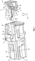
Figure 1 shows a perspective depiction of ahousing 1 for a plug to form a plugging connection with a further housing. Thehousing 1 has acontact space 2 open on both sides, with contacts, in particular electrical contacts, being able to be provided in thecontact space 2. Thehousing 1 is formed to be plugged together with a further housing of a counter-plug to form a contact connection. Furthermore, on the right, beside thehousing 1, adisplay unit 4 is depicted in perspective. Thedisplay unit 4 is provided to indicate complete plugging of the counter-plug into thehousing 1. Thedisplay unit 4 has aguide element 8 and alocking element 5. The lockingelement 5 has aresilient bridge 6. Afirst end 10 of thebridge 6 is firmly connected to theguide element 8. A second end 9 of thebridge 6 is formed as a free end 9 and spaced apart from theguide element 8. - The
guide element 8 has two guidingstructures 11, 12 on the sides. The guidingstructures 11,12 have laterally outwardly protrudingengagement elements 32, 33. In addition, theguide element 8 has a blockingsection 13 in the centre. On the blockingsection 13, anabutment surface 14 is formed on a side facing thebridge 6. The blockingsection 13 is arranged on a plane with thebridge 6. Theguide element 8 is formed to be preferably mirror-symmetrical relative to a central plane. - An
engagement section 15 is formed on the second end 9 of thebridge 6. Furthermore, thebridge 6 has afurther bridge 16. Thefurther bridge 16 constitutes a supporting element arranged between thebridge 6 and theguide element 8. Thefurther bridge 16 is fixed to thebridge 6 by a first further end 17 adjacent to theengagement section 15. A secondfurther end 18 of thefurther bridge 16 is arranged at thebridge 6 close to thefirst end 10 of thebridge 6. Thefurther bridge 16 has afirst section 19, which extends starting from the first further end 17 in the direction of theguide element 8. Thefirst section 19 merges into asecond section 21 via abend 20. In the depicted embodiment, thefirst section 19 is arranged straight starting from the first further end 17 in the direction of theguide element 8. Via thebend 20, thefurther bridge 16 is guided downwards via thesecond section 21 in the direction of thebridge 6 and somewhat set back in the direction of the first further end 17. Thebend 20 is thus arranged closer to theguide element 8 than the secondfurther end 18 of thefurther bridge 16. Thebend 20 has afurther abutment surface 57 facing theguide element 8. In this manner, the first section and the second section of thefurther bridge 16 delimit an angle which is smaller than 90°. Thefurther bridge 16 can have a smaller cross-section than thebridge 6. Depending on the design chosen, the first and thesecond sections - Above the
contact space 2, thehousing 1 has a guidingspace 3 for receiving thedisplay unit 4. The guidingspace 3 is delimited by anupper side 22 of thehousing 1, twofurther side walls housing section 25. Thehousing section 25 is arranged opposite, and spaced apart from, theupper side 22. The first and secondfurther side walls upper side 22. Thehousing section 25 is connected, in particular integrally connected, to asecond end 40 of thehousing 1 in anend region 26. In addition, thehousing section 25 is formed, at threefurther sides housing 1. -
Figure 2 shows thehousing 1 with thedisplay unit 4, which is situated in an initial position and which is borne movably on thehousing 1 in a manner allowing it to be shifted along a longitudinal axis of thehousing 1. The longitudinal axis of thehousing 1 is located in the x-direction of the depicted coordinate system. For longitudinal guiding, thefurther side walls lateral recesses second guiding structures 11, 12. - The
housing section 25 has afirst recess 27 through which theengagement section 15 of thelocking element 5 protrudes. Adjacent to thefirst recess 27, afirst stop 28 is formed at thehousing section 25. Theengagement section 15 abuts on thefirst stop 28. Thus thedisplay unit 4 can be shifted, from the depicted initial position, no further along the x-direction in the direction of thesecond end 40 of thehousing 1. Thehousing section 25 additionally has asecond recess 29, which is arranged closer to thesecond end 40 of thehousing 1 than thefirst recess 27 along the x-direction. - The first and the second
further side walls lateral recesses engagement elements 32, 33 of the guidingstructures 11, 12 engage. The guide element is thus also reliably fixed to the housing and borne to be shiftable in the longitudinal direction. -
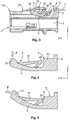
Figure 3 shows a schematic cross-section through thehousing 1 according toFigure 2 . In this depiction, theguide element 8 is acted upon by a force F which attempts to move thedisplay unit 4, starting from the present initial position, in the direction of thesecond end 40 of thehousing 1, into an assembly position. In this case, theengagement section 15 of thelocking element 5 is supported against thefirst stop 28 of thehousing 1. As a result, theengagement section 15 is bent somewhat upwards in the z-direction away from a centre of thehousing 1. Consequently, the supporting element, which is formed in the shape of the further bent-downbridge 16, comes into abutment on theabutment surface 14 of the blockingsection 13 of theguide element 8 in the region of thebend 20. Further bending of thebridge 6 is thus blocked by the abutment of thefurther bridge 16 on theguide element 8. Thus, despite the great flexibility of thebridge 6, it can be ensured, with the aid of thefurther bridge 16, that even large forces F cannot deform thebridge 6 so strongly that theengagement section 15 slips downwards out of thefirst recess 27 and is moved downwards away from thefirst stop 28 and triggers a movement of thedisplay unit 4 along the X axis. -
Figure 4 shows a schematic depiction of thedisplay unit 4 with a force F, which acts in the direction of the arrow toward the free end of thebridge 6. It can be seen here that theengagement section 15, due to the great flexibility of thebridge 6, can be moved downwards out of the rest state with little force. A bending plane in which thelocking element 5 can be moved is arranged in the z-x plane. -
Figure 5 shows theengagement section 15 being acted upon by a force F, depicted in the form of the arrow, in a situation according toFigure 3 in which theengagement section 15 abuts on thefirst stop 28 of the housing, and in which thedisplay unit 4 nevertheless is intended to be moved from the initial position into an assembly position by applying a force F. - In this situation, the
bridge 6 is bent in the bending plane, i.e. in the z-x plane, in a blocking direction toward theguide element 8. In this case, thefurther bridge 16 comes into abutment on the blockingsection 13. Thus, even with high forces F, a further deformation of thebridge 6, and thus a further shift of theengagement section 15 away from the first stop, is prevented. The stability of thelocking element 5 is thus significantly increased with the aid of thefurther bridge 16 in the blocking direction. -
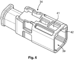
Figure 6 shows a schematic depiction of afurther housing 34 of a counter-plug. Thefurther housing 34 has a receivingaperture 39, into which thesecond end 40 of thehousing 1 is pushed when the housing is being assembled. On an upper side, thefurther housing 34 has a furtherfirst recess 41. In this manner, anactuation strip 42 is formed on the front side. When the two housings are in the completely plugged state, theengagement section 15 is arranged in the furtherfirst recess 41 and is thus freely accessible for an actuation. Electrical and/or any other type of contacts can be arranged in thefurther housing 34. In addition, thefurther housing 34 can be provided with electrical cables or any other type of cables, in particular with optical cables, which are connected to the contacts of the further housing. -
Figure 7 shows a schematic depiction of a partial cut-out of thehousing 1 which is being pushed into the receivingaperture 39 of thefurther housing 34 of a counter-plug by thesecond end 40. To simplify the depiction, only a cut-out of thehousing 1 and a cross-section of theactuation strip 42 are depicted. During assembly, theactuation strip 42 of thefurther housing 34 slides on the upper side of thehousing section 25 in the direction of thefirst recess 27. Thehousing section 25 has a ramp-like section 35, which is arranged between the first and the second recesses 27, 29. The ramp-like section 35 has, in the direction of thefirst recess 27, a height which increases in the z axis. -
Figure 8 shows the situation in which the actuation strip of thefurther housing 34 is pushed over the ramp-like section 35. Since thehousing section 25 is formed in an elastically resilient manner, thehousing section 25 is pressed downwards in the direction of a centre of thehousing 1. -
Figure 9 shows the situation in which thefurther housing 34 is arranged over thefirst recess 27. Thehousing section 25 is sprung back into the initial position again as inFig. 7 . Simultaneously, the free end of thelocking element 5, i.e. theengagement section 15 has been deflected out of the rest state in the direction of a centre of thehousing 1, as schematically depicted inFigure 4 . In this case, thebridge 6 has been bent downwards in the direction of a centre of thehousing 1. - In this situation, the
engagement section 15, seen along the z axis, is arranged underneath thefirst stop 28 in an activation position. In this state of theengagement section 15, thedisplay unit 4 can be shifted along the x axis in the direction of thesecond recess 29. In this situation, thefurther housing 34 of the further plug is completely plugged onto thehousing 1. In this position, electrical contacts of thehousing 1 and electrical contacts of thefurther housing 34, for example, can be arranged in a desired contact position. In addition, in this situation, sealing regions between thehousing 1 and thefurther housing 34 can be situated in an optimum position. Only in this plugging position is it possible to move thedisplay unit 4 from the initial position into an assembly position, for example by a manual actuation of theguide element 8. In this case, theengagement section 15 slides through under thefirst stop 28 in the direction of thesecond recess 29. When thesecond recess 29 is reached, the lockingelement 5 springs into a rest state again, as depicted inFigure 9 . - Due to the limited possibility of deflection of the
locking element 5 in the locking direction, as is depicted inFigure 5 , a small overlap between theengagement section 15 and thefirst stop 28 is already sufficient to block a movement of thedisplay unit 4. Thedisplay unit 4 is thus only released when thefurther housing 34 is situated precisely in the desired plugging position and theengagement section 15 is completely deflected inwards by thefirst stop 28 in the direction of a centre of thehousing 1. - It can be seen in
Figure 10 that, in the assembly position, thedisplay unit 4, with the blockingsection 13, is situated under afree end section 36 of thehousing section 25. In addition, thefurther housing 34 is arranged in the region of thefirst recess 27 and engages behind thefirst stop 28. To pull thefurther housing 34 off of thehousing 1, it would be necessary to press thehousing section 25, and in particular the ramp-like section 35, in the direction of a centre of thehousing 1. However, this is not possible in the depicted position of thedisplay unit 4, because thefree end section 36 rests on an upper side of the blockingsection 13 and thus thehousing section 25 cannot be moved in the direction of a centre of thehousing 1. In addition, theengagement section 15 of thelocking element 5 engages in the second recess. The second engagement section is blocked by asecond stop 56, which in thehousing section 25 adjacent to thesecond recess 29 and adjacent to the ramp-like section 35 against pulling back in the direction of thefirst recess 27. - If it is intended to pull the
further housing 34 of the further plug off of thehousing 1 again, theengagement section 15 of thelocking element 5 is pressed by a tool or by hand in the direction of a centre of thehousing 1 and at the same time a force is introduced at theguide element 8, which force moves thedisplay unit 4 from the assembly position back into the initial position again. If thedisplay unit 4 is situated in the initial position again, thehousing section 25 can be pressed in the direction of the centre of thehousing 1, such that theactuation strip 42 can be pulled away from thehousing 1 over thefirst stop 28 and the ramp-like section 35. -
Figure 11 shows a perspective depiction of a view of thehousing 1 which does not depict thedisplay unit 4. In this depiction, it can be clearly seen that thehousing section 25 is formed as an elongate section which is connected to thehousing 1 only at a narrow side in theend region 26. Amovable housing section 25 is thus provided with simple means. -
Figure 12 shows a schematic cross-section of an embodiment of thehousing 1, in which anelectrical contact 37 is assembled with anelectrical cable 38. Instead of electrical contacts and electrical cables, any other type of contacts and any other type of cable, for example, such as a light conductor, can be mounted on thehousing 1. In the case of light conductors, it is also possible to dispense with the contacts. -
Figures 13 to 17 show various embodiments of thedisplay units 4 with various forms of thelocking element 5. - In the case of the embodiment of the
display unit 4 inFigure 13 , the supporting element is formed in the shape of a simplefurther bridge 16, which extends starting from thebridge 6 in a straight direction toward theguide element 8 of thedisplay unit 4 and ends in a definedspacing 43 in front of the blockingsection 13 or abuts on the blockingsection 13. Thus, in this embodiment too, the lockingelement 5 can be moved in the bending plane, i.e. in the x-z plane, away from theguide element 8 with a small amount of force. In the direction toward theguide element 8, i.e. in the blocking direction, theengagement section 15 can be moved with a small amount of force only until thespacing 43 is bridged. If thefurther bridge 16 abuts on theguide element 8, thefurther bridge 16 impedes the further deformation of thebridge 6 in the direction of theguide element 8. -
Figure 14 shows a further embodiment of the locking element of thedisplay unit 4, with the supporting element in this embodiment being formed as a bent-downfurther bridge 16 comprising afirst section 19 and asecond section 21. In this embodiment, an end of thesecond section 21 is not connected to thebridge 6, but rather is formed as a free end. In addition, in this embodiment the first and thesecond sections second sections further bridge 16 causes thebridge 6 to be supported on theguide element 8 when thebridge 6 deforms in the direction of theguide element 8. -
Figure 15 shows a further embodiment of thedisplay unit 4, with the supporting element being formed in this embodiment in the form of aplate 44 moulded onto thebridge 6. Theplate 44 is formed between thebridge 6 and a support surface of theguide element 8. In the rest position of thebridge 6, theplate 44 has a specifiedspacing 43 from the supporting surface of theguide element 8 or abuts on theguide element 8 with a lateral surface. If thebridge 6 is deformed in the direction of theguide element 8, theplate 44 comes into abutment on the supportingsurface 45 and blocks a further deformation of thebridge 6. Depending on the embodiment selected, theplate 44 may also have recesses, in order to save material, without reducing the rigidity of theplate 44 below a specified value. -
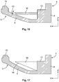
Figures 16 and 17 schematically show exemplary embodiments in which the supporting element is formed on theguide element 8 itself. InFigure 16 , afurther bridge 16 is guided from theguide element 8 in the direction of thebridge 6 of thelocking element 5. In the rest state of thebridge 6, a free end of thefurther bridge 16 has a specifiedspacing 43 from thebridge 6. If thebridge 6 is deformed in the x-z plane bending plane in the direction of theguide element 8, thebridge 6 comes into abutment on the free end of thefurther bridge 16. A further deformation of thebridge 6 in the direction of theguide element 8 is thus blocked. -
Figure 17 shows a further embodiment in which the supporting element is formed in the shape of aplate 44 or a block on theguide element 8. When thebridge 6 is in the resting position, afurther abutment surface 46 of theplate 44 has a specifiedspacing 43 from thebridge 6 or abuts on thebridge 6. If thebridge 6 is bent in the direction of thelocking element 5, thebridge 6 comes into abutment on thefurther abutment surface 46 of theplate 44, in a front end region of theplate 44. In this embodiment too, thebridge 6 is blocked from moving any further in the direction of thelocking element 5. Theplate 44 may likewise have recesses. - In all embodiments, the supporting elements, in cross-section relative to a longitudinal extent, have a smaller material thickness in at least one direction than the
bridge 6. With the aid of the supporting element which is arranged between the bridge of the locking element and a further section of thedisplay unit 4 in a bending plane of thebridge 6, a bending of thebridge 6 in a locking direction is increased without altering the flexibility of thebridge 6 in the bending plane counter to the locking direction. - Both the
display unit 4 and thehousing 1 can be made of plastic. The supporting element and the display unit are also preferably formed in one piece. The display unit constitutes a housing position assurance, which is also called a CPA (Connector Position Assurance), with which a correct testing of the correct plugging position of the housing with a further housing can be tested. The housing and the further housing can represent a connector device for electrical or optical signals, for example. - The
housing 1 and thefurther housing 34 can have not only one, but rather also a number of contacts and/or cables. In addition, depending on the selected embodiment, it is possible for not only one display unit, but rather also a number of display units, to be arranged on the housing. -
Figure 18 shows a schematic depiction of a top view of a further embodiment of thehousing 1, in which thehousing section 25 is flexibly connected to thefurther housing 1. In this embodiment, in contrast to the embodiments described hitherto, thehousing section 25 is not exposed on three sides, but rather is connected to thehousing 1 on three sides. The flexibility of thehousing section 25 is created for example by correspondingly thinned connectingsections 55 for example in the side region of thehousing section 25 with thefurther housing 1. -
- 1
- housing
- 2
- contact space
- 3
- guiding space
- 4
- display unit
- 5
- locking element
- 6
- bridge
- 8
- guide element
- 9
- second end of the bridge
- 10
- first end of the bridge
- 11
- first guiding structure
- 12
- second guiding structure
- 13
- blocking section
- 14
- abutment surface
- 15
- engagement section
- 16
- further bridge
- 17
- first further end
- 18
- second further end
- 19
- first section
- 20
- bend
- 21
- second section
- 22
- upper side
- 23
- first further side wall
- 24
- second further side wall
- 25
- housing section
- 26
- end region
- 27
- first recess
- 28
- first stop
- 29
- second recess
- 30
- first further recess
- 31
- second further recess
- 32
- first engagement element
- 33
- second engagement element
- 34
- further housing
- 35
- ramp-like section
- 36
- free end section
- 37
- electrical contact
- 38
- electrical cable
- 39
- receiving aperture
- 40
- second end of the housing
- 41
- further first recess
- 42
- actuation strip
- 43
- spacing
- 44
- plate
- 45
- supporting surface
- 46
- further abutment surface
- 51
- first side
- 52
- second side
- 53
- third side
- 54
- second end of the housing
- 55
- connecting section
- 56
- second stop
- 57
- further abutment surface
- F
- force
Claims (15)
- A housing (1) for a plug having a contact space (3) for contacts, wherein the housing (1) is configured in such a way that it may be plugged together with a counter-plug, having a display unit (4), wherein the display unit (4) is provided to indicate a complete plugging of the counter-plug into the housing (1), wherein the display unit (4) is borne in a shiftable manner along a longitudinal axis of the housing (1) between an initial position and an assembly position, wherein the display unit (4) comprises a locking element (5) and a guide element (8), wherein the locking element (5) comprises a resilient bridge (6), wherein the bridge (6) is fixed to the guide element (8) by one end (10), wherein in the initial position of the display unit (4) a first stop (28) of the housing (1,25) prevents the display unit from shifting by abutment of the free end (15) of the bridge (6) on the first stop (28) of the housing (1), wherein the free end (15) of the bridge (6) is bent in a bending plane in the direction of the guide element (8) when shifting in the direction of the first stop, wherein a supporting element (16,44) is arranged between the bridge (6) and the guide element (8) in the bending plane in such a way that, when the bridge (6) deforms in the direction of the guide element (8), the bridge (6) is supported at the guide element (8) via the supporting element (16,44)and a deformation of the bridge (6) away from the abutment on the first stop (28) is prevented.
- The housing according to Claim 1, wherein the locking element (5) may be deformed from a rest state into an activation position by an actuation strip (42) of the counter-plug (34) when the housing (1) is completely plugged together with the counter-plug (34), wherein, when the locking element (6) is in the activation position, a shifting of the display unit (4) into the assembly position is triggered, wherein the locking element springs back into the rest state after the display unit (4) has been shifted into the assembly position, wherein, when the locking element (6) is in the rest state, a shifting of the display unit (4) is blocked by the abutment of the locking element (6) on a second stop (56) of the housing (1).
- The housing according to Claim 1 or 2, wherein the supporting element on the bridge (6) of the locking element (5) is formed as a further bridge, wherein the further bridge (16) extends starting from the bridge in the direction of a supporting surface of the guide element (8).
- The housing according to Claim 1 or 2, wherein the supporting element (44) is formed on the guide element (8), wherein the supporting element (44) extends in the direction of the locking element (5).
- The housing according to Claim 3, wherein the further bridge (16) is connected to the bridge (6) by both ends (17,18).
- The housing according to any one of Claims 1 to 3 or 5, wherein the further bridge (16) has a first section (19) which is guided in the direction of the guide element (8), wherein the first section (19) merges into a second section (21) via a bend (20), wherein the second section (21) is guided for at least a given distance in the direction of the bridge (6).
- The housing according to Claim 6, wherein, in the region of the bend (20), the first and the second sections (19,21) of the further bridge (16) delimit an angle which is smaller than 90°, and wherein the second section (21) is guided in the direction of the bridge (6) at least partly away from the abutment surface (46) of the guide element (8) in the direction of the free end (15) of the bridge (6).
- The housing according to Claim 6 or 7, wherein the bend (20) has an abutment surface (57), wherein the further abutment surface (57) faces the abutment surface (46) of the guide element 8, and wherein, when the bridge (6) is deformed in the event of abutment on the first stop (28) of the housing (1), the further abutment surface (57) of the bend (20) comes into abutment on the abutment surface (46) of the guide element (8) and supports the bridge (6) at the guide element (8).
- The housing according to any one of the preceding claims, wherein the housing (1) has a housing section (25), wherein the housing section (25) is formed to be flexible in the direction of the bending plane, wherein a first recess (27) is formed in the housing section (25), wherein the free end of the bridge (6) is arranged in the first recess (27) of the housing section (25) in the initial position of the display unit (4), and wherein the first stop (28) of the housing (1) is formed adjacent to the first recess (27) at the housing section (25).
- The housing according to Claim 9, wherein the housing section (25) extends along a longitudinal axis of the housing (1), wherein the housing section (25) has an elongate strip form, wherein a narrow strip end (26) is integrally connected to the housing (1), and wherein the housing section is formed to be free on three sides and spaced apart from the housing (1), and wherein the housing section (25) is formed resiliently in a manner which allows it to be deformed in the direction of a centre of the housing.
- The housing according to any one of Claims 9 or 10, wherein a second recess (29) is formed in the housing section (25), wherein, in the assembly position of the display unit (4), the free end (15) of the bridge (6) engages in the second recess (29) of the housing section, wherein the guide element (8) has a blocking section (13), and wherein the blocking section (13) in the assembly position of the display unit is arranged under the housing section (25) and blocks a deformation of the housing section in the direction of a centre of the housing (1).
- The housing according to any one of Claims 9 to 11, wherein in the completely plugged state the counter-plug engages with an actuation strip (42) at least partly in the first recess (27), wherein the actuation strip (42) moves the free end (15) of the bridge (6) out of the rest state in the direction of a centre of the housing, such that the free end (15) of the bridge (6) is moved away from the first stop (28), wherein the actuation strip (42) engages behind the first stop (28).
- The housing according to any one of the preceding claims, wherein the end (10) of the bridge (6) which is connected to the guide element (8) is arranged closer to a central axis of the housing than the free end (15) of the bridge (6) .
- The housing according to any one of the preceding claims, wherein the bridge (6) has, at least in sections, a shape which is bent outwards in the bending plane away from a central axis of the housing (1), or wherein the bridge (6) has, at least in sections, a straight shape directed outwards in the bending plane away from a central axis of the housing (1).
- The housing according to any one of the preceding claims, wherein the bridge (6), in cross-section, in particular in the smallest cross-section, has a greater width and/or greater height than the supporting element (16,44).
Applications Claiming Priority (1)
| Application Number | Priority Date | Filing Date | Title |
|---|---|---|---|
| DE102019113491.9A DE102019113491A1 (en) | 2019-05-21 | 2019-05-21 | Housing for a plug with a display device |
Publications (2)
| Publication Number | Publication Date |
|---|---|
| EP3742560A1 true EP3742560A1 (en) | 2020-11-25 |
| EP3742560B1 EP3742560B1 (en) | 2023-04-12 |
Family
ID=70740542
Family Applications (1)
| Application Number | Title | Priority Date | Filing Date |
|---|---|---|---|
| EP20175247.4A Active EP3742560B1 (en) | 2019-05-21 | 2020-05-18 | Housing for a plug comprising a display unit |
Country Status (4)
| Country | Link |
|---|---|
| US (1) | US11114799B2 (en) |
| EP (1) | EP3742560B1 (en) |
| CN (1) | CN111987521B (en) |
| DE (1) | DE102019113491A1 (en) |
Cited By (1)
| Publication number | Priority date | Publication date | Assignee | Title |
|---|---|---|---|---|
| EP4002604A4 (en) * | 2019-07-18 | 2023-08-02 | Tyco Electronics Japan G.K. | Connector |
Families Citing this family (1)
| Publication number | Priority date | Publication date | Assignee | Title |
|---|---|---|---|---|
| US11387604B2 (en) * | 2020-10-14 | 2022-07-12 | Aptiv Technologies Limited | Wave connector position assurance lock with dual overlap connector lock |
Citations (2)
| Publication number | Priority date | Publication date | Assignee | Title |
|---|---|---|---|---|
| DE102013006830A1 (en) * | 2012-06-29 | 2014-01-02 | Lear Corp. | Connector position assurance device for a connector assembly |
| US20140287614A1 (en) * | 2012-01-16 | 2014-09-25 | Nissan Motor Co., Ltd. | Power-feeding connector |
Family Cites Families (17)
| Publication number | Priority date | Publication date | Assignee | Title |
|---|---|---|---|---|
| JPH1126089A (en) * | 1997-07-08 | 1999-01-29 | Yazaki Corp | Lock detection connector |
| JP3750916B2 (en) * | 2000-07-18 | 2006-03-01 | 矢崎総業株式会社 | Connector mating structure |
| US7201599B2 (en) * | 2004-03-23 | 2007-04-10 | Fci Americas Technology, Inc. | Electrical connector latch |
| US7399195B2 (en) * | 2006-12-06 | 2008-07-15 | J.S.T. Corporation | Connector position assurance device and connector assembly incorporating the same |
| DE102007033942B4 (en) | 2007-07-19 | 2009-08-27 | Phoenix Contact Gmbh & Co. Kg | Electrical terminal |
| US8016606B1 (en) * | 2011-01-10 | 2011-09-13 | J.S.T. Corporation | Unstressed connector position assurance device and connector assembly |
| US8747146B2 (en) * | 2011-05-04 | 2014-06-10 | Tyco Electronics Corporation | Electrical connector having connector position assurance |
| CN202601982U (en) * | 2012-06-08 | 2012-12-12 | 泰科电子(上海)有限公司 | Connector assembly and connector product |
| DE102013205447B4 (en) | 2013-03-27 | 2022-06-09 | Lisa Dräxlmaier GmbH | Electrical connector and electrical connector with such a connector |
| US10014618B2 (en) | 2015-02-20 | 2018-07-03 | J.S.T. Corporation | Connector with terminal position assurance |
| DE102015103898A1 (en) | 2015-03-17 | 2016-09-22 | Daniel Schönfelder | Arrangement with a mattress and an at least allergenreduzierenden mattress cover and articles |
| JP6287987B2 (en) * | 2015-07-22 | 2018-03-07 | 住友電装株式会社 | connector |
| US10135189B2 (en) * | 2015-09-02 | 2018-11-20 | J.S.T. Corporation | Connector apparatus having male and female connector assemblies and a connector position assurance device, a male connector assembly, a female connector assembly, and a method for assembling the connector apparatus |
| JP6213592B2 (en) * | 2016-02-25 | 2017-10-18 | 第一精工株式会社 | connector |
| JP6569131B2 (en) * | 2016-04-26 | 2019-09-04 | 株式会社オートネットワーク技術研究所 | Electrical connection device having fitting detection function |
| JP6417369B2 (en) * | 2016-07-29 | 2018-11-07 | 矢崎総業株式会社 | connector |
| EP3288122B1 (en) * | 2016-08-22 | 2020-07-22 | J.S.T. Corporation | A connector position assurance locking mechanism and method of operating the connector position assurance locking mechanism |
-
2019
- 2019-05-21 DE DE102019113491.9A patent/DE102019113491A1/en active Pending
-
2020
- 2020-05-18 EP EP20175247.4A patent/EP3742560B1/en active Active
- 2020-05-19 US US16/878,132 patent/US11114799B2/en active Active
- 2020-05-21 CN CN202010434525.1A patent/CN111987521B/en active Active
Patent Citations (2)
| Publication number | Priority date | Publication date | Assignee | Title |
|---|---|---|---|---|
| US20140287614A1 (en) * | 2012-01-16 | 2014-09-25 | Nissan Motor Co., Ltd. | Power-feeding connector |
| DE102013006830A1 (en) * | 2012-06-29 | 2014-01-02 | Lear Corp. | Connector position assurance device for a connector assembly |
Cited By (2)
| Publication number | Priority date | Publication date | Assignee | Title |
|---|---|---|---|---|
| EP4002604A4 (en) * | 2019-07-18 | 2023-08-02 | Tyco Electronics Japan G.K. | Connector |
| US11962106B2 (en) | 2019-07-18 | 2024-04-16 | Tyco Electronics Japan G.K. | Connector |
Also Published As
| Publication number | Publication date |
|---|---|
| CN111987521B (en) | 2023-12-19 |
| CN111987521A (en) | 2020-11-24 |
| EP3742560B1 (en) | 2023-04-12 |
| US11114799B2 (en) | 2021-09-07 |
| DE102019113491A1 (en) | 2020-11-26 |
| US20200373709A1 (en) | 2020-11-26 |
Similar Documents
| Publication | Publication Date | Title |
|---|---|---|
| CN113346258B (en) | Connection device and electronic equipment | |
| US10553978B2 (en) | Contacting device for contacting an electrical conductor to an electrical conductor path | |
| EP3742560A1 (en) | Housing for a plug comprising a display unit | |
| EP3389140B1 (en) | Electrical connector | |
| JP2015510242A (en) | Electrical connector strain relief | |
| EP1978606A2 (en) | Slide lock panel-mount connector | |
| EP3229321A1 (en) | Power source connector device | |
| JP2015506576A (en) | Board mount electrical connector | |
| US11038289B2 (en) | Electrical connector | |
| CN104810644A (en) | Connector | |
| US11316288B2 (en) | Electrical connector with slider operated clamp spring arm | |
| KR20220057573A (en) | terminal block | |
| US11594839B2 (en) | Plug connector assembly | |
| CN111613931A (en) | Holding frame for a plug connector | |
| EP2869403A1 (en) | Contact element for a plug type connector and arrangement comprising a contact element | |
| JP4475185B2 (en) | connector | |
| WO2018163738A1 (en) | Electric component mounting structure and automatic transmission wiring unit | |
| US8096821B2 (en) | Electrical card connector | |
| JP7418925B2 (en) | Plug-in terminal structure | |
| EP1901400A2 (en) | A wire cover and a locking construction therefor | |
| KR20230009959A (en) | Connection units, connection devices and electronics | |
| KR20180051103A (en) | Connector for preventing bending of terminal | |
| US20100151730A1 (en) | Contact housing and electrical contact device | |
| JP6546973B2 (en) | Flat conductor connector | |
| JP6613129B2 (en) | Metal terminal |
Legal Events
| Date | Code | Title | Description |
|---|---|---|---|
| PUAI | Public reference made under article 153(3) epc to a published international application that has entered the european phase |
Free format text: ORIGINAL CODE: 0009012 |
|
| STAA | Information on the status of an ep patent application or granted ep patent |
Free format text: STATUS: THE APPLICATION HAS BEEN PUBLISHED |
|
| AK | Designated contracting states |
Kind code of ref document: A1 Designated state(s): AL AT BE BG CH CY CZ DE DK EE ES FI FR GB GR HR HU IE IS IT LI LT LU LV MC MK MT NL NO PL PT RO RS SE SI SK SM TR |
|
| AX | Request for extension of the european patent |
Extension state: BA ME |
|
| STAA | Information on the status of an ep patent application or granted ep patent |
Free format text: STATUS: REQUEST FOR EXAMINATION WAS MADE |
|
| 17P | Request for examination filed |
Effective date: 20210521 |
|
| RBV | Designated contracting states (corrected) |
Designated state(s): AL AT BE BG CH CY CZ DE DK EE ES FI FR GB GR HR HU IE IS IT LI LT LU LV MC MK MT NL NO PL PT RO RS SE SI SK SM TR |
|
| GRAP | Despatch of communication of intention to grant a patent |
Free format text: ORIGINAL CODE: EPIDOSNIGR1 |
|
| STAA | Information on the status of an ep patent application or granted ep patent |
Free format text: STATUS: GRANT OF PATENT IS INTENDED |
|
| INTG | Intention to grant announced |
Effective date: 20221017 |
|
| GRAS | Grant fee paid |
Free format text: ORIGINAL CODE: EPIDOSNIGR3 |
|
| GRAA | (expected) grant |
Free format text: ORIGINAL CODE: 0009210 |
|
| STAA | Information on the status of an ep patent application or granted ep patent |
Free format text: STATUS: THE PATENT HAS BEEN GRANTED |
|
| AK | Designated contracting states |
Kind code of ref document: B1 Designated state(s): AL AT BE BG CH CY CZ DE DK EE ES FI FR GB GR HR HU IE IS IT LI LT LU LV MC MK MT NL NO PL PT RO RS SE SI SK SM TR |
|
| REG | Reference to a national code |
Ref country code: GB Ref legal event code: FG4D |
|
| REG | Reference to a national code |
Ref country code: CH Ref legal event code: EP |
|
| REG | Reference to a national code |
Ref country code: DE Ref legal event code: R096 Ref document number: 602020009613 Country of ref document: DE |
|
| REG | Reference to a national code |
Ref country code: DE Ref legal event code: R082 Ref document number: 602020009613 Country of ref document: DE Representative=s name: WILHELM & BECK, DE Ref country code: DE Ref legal event code: R082 Country of ref document: DE |
|
| REG | Reference to a national code |
Ref country code: IE Ref legal event code: FG4D |
|
| REG | Reference to a national code |
Ref country code: DE Ref legal event code: R082 Ref document number: 602020009613 Country of ref document: DE Representative=s name: WILHELM & BECK, DE |
|
| REG | Reference to a national code |
Ref country code: AT Ref legal event code: REF Ref document number: 1560316 Country of ref document: AT Kind code of ref document: T Effective date: 20230515 |
|
| PGFP | Annual fee paid to national office [announced via postgrant information from national office to epo] |
Ref country code: FR Payment date: 20230510 Year of fee payment: 4 Ref country code: DE Payment date: 20230425 Year of fee payment: 4 Ref country code: IT Payment date: 20230531 Year of fee payment: 4 |
|
| REG | Reference to a national code |
Ref country code: LT Ref legal event code: MG9D |
|
| REG | Reference to a national code |
Ref country code: NL Ref legal event code: MP Effective date: 20230412 |
|
| REG | Reference to a national code |
Ref country code: AT Ref legal event code: MK05 Ref document number: 1560316 Country of ref document: AT Kind code of ref document: T Effective date: 20230412 |
|
| PG25 | Lapsed in a contracting state [announced via postgrant information from national office to epo] |
Ref country code: NL Free format text: LAPSE BECAUSE OF FAILURE TO SUBMIT A TRANSLATION OF THE DESCRIPTION OR TO PAY THE FEE WITHIN THE PRESCRIBED TIME-LIMIT Effective date: 20230412 |
|
| PG25 | Lapsed in a contracting state [announced via postgrant information from national office to epo] |
Ref country code: SE Free format text: LAPSE BECAUSE OF FAILURE TO SUBMIT A TRANSLATION OF THE DESCRIPTION OR TO PAY THE FEE WITHIN THE PRESCRIBED TIME-LIMIT Effective date: 20230412 Ref country code: PT Free format text: LAPSE BECAUSE OF FAILURE TO SUBMIT A TRANSLATION OF THE DESCRIPTION OR TO PAY THE FEE WITHIN THE PRESCRIBED TIME-LIMIT Effective date: 20230814 Ref country code: NO Free format text: LAPSE BECAUSE OF FAILURE TO SUBMIT A TRANSLATION OF THE DESCRIPTION OR TO PAY THE FEE WITHIN THE PRESCRIBED TIME-LIMIT Effective date: 20230712 Ref country code: ES Free format text: LAPSE BECAUSE OF FAILURE TO SUBMIT A TRANSLATION OF THE DESCRIPTION OR TO PAY THE FEE WITHIN THE PRESCRIBED TIME-LIMIT Effective date: 20230412 Ref country code: AT Free format text: LAPSE BECAUSE OF FAILURE TO SUBMIT A TRANSLATION OF THE DESCRIPTION OR TO PAY THE FEE WITHIN THE PRESCRIBED TIME-LIMIT Effective date: 20230412 |
|
| PG25 | Lapsed in a contracting state [announced via postgrant information from national office to epo] |
Ref country code: RS Free format text: LAPSE BECAUSE OF FAILURE TO SUBMIT A TRANSLATION OF THE DESCRIPTION OR TO PAY THE FEE WITHIN THE PRESCRIBED TIME-LIMIT Effective date: 20230412 Ref country code: PL Free format text: LAPSE BECAUSE OF FAILURE TO SUBMIT A TRANSLATION OF THE DESCRIPTION OR TO PAY THE FEE WITHIN THE PRESCRIBED TIME-LIMIT Effective date: 20230412 Ref country code: LV Free format text: LAPSE BECAUSE OF FAILURE TO SUBMIT A TRANSLATION OF THE DESCRIPTION OR TO PAY THE FEE WITHIN THE PRESCRIBED TIME-LIMIT Effective date: 20230412 Ref country code: LT Free format text: LAPSE BECAUSE OF FAILURE TO SUBMIT A TRANSLATION OF THE DESCRIPTION OR TO PAY THE FEE WITHIN THE PRESCRIBED TIME-LIMIT Effective date: 20230412 Ref country code: IS Free format text: LAPSE BECAUSE OF FAILURE TO SUBMIT A TRANSLATION OF THE DESCRIPTION OR TO PAY THE FEE WITHIN THE PRESCRIBED TIME-LIMIT Effective date: 20230812 Ref country code: HR Free format text: LAPSE BECAUSE OF FAILURE TO SUBMIT A TRANSLATION OF THE DESCRIPTION OR TO PAY THE FEE WITHIN THE PRESCRIBED TIME-LIMIT Effective date: 20230412 Ref country code: GR Free format text: LAPSE BECAUSE OF FAILURE TO SUBMIT A TRANSLATION OF THE DESCRIPTION OR TO PAY THE FEE WITHIN THE PRESCRIBED TIME-LIMIT Effective date: 20230713 Ref country code: AL Free format text: LAPSE BECAUSE OF FAILURE TO SUBMIT A TRANSLATION OF THE DESCRIPTION OR TO PAY THE FEE WITHIN THE PRESCRIBED TIME-LIMIT Effective date: 20230412 |
|
| PG25 | Lapsed in a contracting state [announced via postgrant information from national office to epo] |
Ref country code: FI Free format text: LAPSE BECAUSE OF FAILURE TO SUBMIT A TRANSLATION OF THE DESCRIPTION OR TO PAY THE FEE WITHIN THE PRESCRIBED TIME-LIMIT Effective date: 20230412 |
|
| REG | Reference to a national code |
Ref country code: CH Ref legal event code: PL |
|
| REG | Reference to a national code |
Ref country code: DE Ref legal event code: R097 Ref document number: 602020009613 Country of ref document: DE |
|
| PG25 | Lapsed in a contracting state [announced via postgrant information from national office to epo] |
Ref country code: SK Free format text: LAPSE BECAUSE OF FAILURE TO SUBMIT A TRANSLATION OF THE DESCRIPTION OR TO PAY THE FEE WITHIN THE PRESCRIBED TIME-LIMIT Effective date: 20230412 |
|
| PG25 | Lapsed in a contracting state [announced via postgrant information from national office to epo] |
Ref country code: MC Free format text: LAPSE BECAUSE OF FAILURE TO SUBMIT A TRANSLATION OF THE DESCRIPTION OR TO PAY THE FEE WITHIN THE PRESCRIBED TIME-LIMIT Effective date: 20230412 |
|
| REG | Reference to a national code |
Ref country code: BE Ref legal event code: MM Effective date: 20230531 |
|
| PG25 | Lapsed in a contracting state [announced via postgrant information from national office to epo] |
Ref country code: SM Free format text: LAPSE BECAUSE OF FAILURE TO SUBMIT A TRANSLATION OF THE DESCRIPTION OR TO PAY THE FEE WITHIN THE PRESCRIBED TIME-LIMIT Effective date: 20230412 Ref country code: SK Free format text: LAPSE BECAUSE OF FAILURE TO SUBMIT A TRANSLATION OF THE DESCRIPTION OR TO PAY THE FEE WITHIN THE PRESCRIBED TIME-LIMIT Effective date: 20230412 Ref country code: RO Free format text: LAPSE BECAUSE OF FAILURE TO SUBMIT A TRANSLATION OF THE DESCRIPTION OR TO PAY THE FEE WITHIN THE PRESCRIBED TIME-LIMIT Effective date: 20230412 Ref country code: MC Free format text: LAPSE BECAUSE OF FAILURE TO SUBMIT A TRANSLATION OF THE DESCRIPTION OR TO PAY THE FEE WITHIN THE PRESCRIBED TIME-LIMIT Effective date: 20230412 Ref country code: LU Free format text: LAPSE BECAUSE OF NON-PAYMENT OF DUE FEES Effective date: 20230518 Ref country code: LI Free format text: LAPSE BECAUSE OF NON-PAYMENT OF DUE FEES Effective date: 20230531 Ref country code: EE Free format text: LAPSE BECAUSE OF FAILURE TO SUBMIT A TRANSLATION OF THE DESCRIPTION OR TO PAY THE FEE WITHIN THE PRESCRIBED TIME-LIMIT Effective date: 20230412 Ref country code: DK Free format text: LAPSE BECAUSE OF FAILURE TO SUBMIT A TRANSLATION OF THE DESCRIPTION OR TO PAY THE FEE WITHIN THE PRESCRIBED TIME-LIMIT Effective date: 20230412 Ref country code: CZ Free format text: LAPSE BECAUSE OF FAILURE TO SUBMIT A TRANSLATION OF THE DESCRIPTION OR TO PAY THE FEE WITHIN THE PRESCRIBED TIME-LIMIT Effective date: 20230412 Ref country code: CH Free format text: LAPSE BECAUSE OF NON-PAYMENT OF DUE FEES Effective date: 20230531 |
|
| PLBE | No opposition filed within time limit |
Free format text: ORIGINAL CODE: 0009261 |
|
| STAA | Information on the status of an ep patent application or granted ep patent |
Free format text: STATUS: NO OPPOSITION FILED WITHIN TIME LIMIT |
|
| REG | Reference to a national code |
Ref country code: IE Ref legal event code: MM4A |
|
| 26N | No opposition filed |
Effective date: 20240115 |
|
| PG25 | Lapsed in a contracting state [announced via postgrant information from national office to epo] |
Ref country code: IE Free format text: LAPSE BECAUSE OF NON-PAYMENT OF DUE FEES Effective date: 20230518 |
|
| PG25 | Lapsed in a contracting state [announced via postgrant information from national office to epo] |
Ref country code: IE Free format text: LAPSE BECAUSE OF NON-PAYMENT OF DUE FEES Effective date: 20230518 |
|
| PG25 | Lapsed in a contracting state [announced via postgrant information from national office to epo] |
Ref country code: SI Free format text: LAPSE BECAUSE OF FAILURE TO SUBMIT A TRANSLATION OF THE DESCRIPTION OR TO PAY THE FEE WITHIN THE PRESCRIBED TIME-LIMIT Effective date: 20230412 |