EP3742458A1 - Power cable with enhanced ampacity - Google Patents
Power cable with enhanced ampacity Download PDFInfo
- Publication number
- EP3742458A1 EP3742458A1 EP20175760.6A EP20175760A EP3742458A1 EP 3742458 A1 EP3742458 A1 EP 3742458A1 EP 20175760 A EP20175760 A EP 20175760A EP 3742458 A1 EP3742458 A1 EP 3742458A1
- Authority
- EP
- European Patent Office
- Prior art keywords
- power cable
- electrical conductor
- conductor
- electrical
- layer
- Prior art date
- Legal status (The legal status is an assumption and is not a legal conclusion. Google has not performed a legal analysis and makes no representation as to the accuracy of the status listed.)
- Granted
Links
Images

Classifications
-
- H—ELECTRICITY
- H01—ELECTRIC ELEMENTS
- H01B—CABLES; CONDUCTORS; INSULATORS; SELECTION OF MATERIALS FOR THEIR CONDUCTIVE, INSULATING OR DIELECTRIC PROPERTIES
- H01B7/00—Insulated conductors or cables characterised by their form
- H01B7/42—Insulated conductors or cables characterised by their form with arrangements for heat dissipation or conduction
-
- H—ELECTRICITY
- H01—ELECTRIC ELEMENTS
- H01B—CABLES; CONDUCTORS; INSULATORS; SELECTION OF MATERIALS FOR THEIR CONDUCTIVE, INSULATING OR DIELECTRIC PROPERTIES
- H01B7/00—Insulated conductors or cables characterised by their form
- H01B7/42—Insulated conductors or cables characterised by their form with arrangements for heat dissipation or conduction
- H01B7/421—Insulated conductors or cables characterised by their form with arrangements for heat dissipation or conduction for heat dissipation
- H01B7/423—Insulated conductors or cables characterised by their form with arrangements for heat dissipation or conduction for heat dissipation using a cooling fluid
Definitions
- the present disclosure relates to the technical field of power cables. Specifically, the present disclosure relates to a power cable with enhanced ampacity.
- Ampacity (also described as current-carrying capacity) is defined as the maximum current, in amperes, that an electrical conductor can carry continuously under the conditions of use without exceeding its temperature rating.
- the ampacity of an electrical conductor depends on its ability to dissipate heat without damage to the electrical conductor or its electrical insulation. This ability to dissipate heat is a function of the temperature rating of the cable electrical insulation material, the electrical resistance of the electrical conductor material, the ambient temperature.
- charging stations can have a power higher than 350 kW.
- US 9,449,739 discloses a power cable apparatus that comprises an elongated thermal conductor, and an electrical conductor layer surrounding at least a portion of the elongated thermal conductor. Heat generated in the power cable is transferred via the elongated thermal conductor to at least one end of the power cable which is connected to a cooling system.
- the apparatus further comprises an electric insulation layer surrounding at least a portion of the electrical conductor layer.
- the apparatus further comprises a thermal insulation layer surrounding at least a portion of the electric insulation layer.
- a second thermal conductor can surround the electrical conductor.
- An electric insulation layer surrounds the second thermal conductor.
- the thermal conductor is manufactured from pyrolytic graphite or carbon nanotubes (CNTs).
- An object of the present disclosure is to provide a power cable which is more efficiently cooled during operation.
- Power cables endowed of a cooling system comprising a cooling duct extended along the electric conductor within a common cable jacket are known in the art. See, for example, WO 2018/104234 and WO 2015/119791 .
- the addition of a cooling duct within the cable jacket increases the cable diameter.
- the just mentioned patent applications relating to power cables for EV charging, provides for a plurality of cooling ducts resulting in a complex cable structure and, accordingly, a complex manufacturing and cable cost increasing.
- the Applicant found that the cooling efficiency of a cooling system for power cable comprising a cooling duct extended along the electric conductor within a common cable jacket could be increased by providing the power cable with a layer of carbon allotrope extended along the electric conductor, in direct contact thereto and interposed between the electric conductor and the cooling system .
- a power cable comprising a cable jacket enclosing:
- the cooling duct is provided in a radial inner position with respect to the electrical conductor and at least partially in direct contact with a carbon allotrope layer.
- the electrical insulation layer is in contact with the electric conductor, with a carbon allotrope layer optionally interposed.
- the cooling duct is provided in a radial outer position with respect to the electrical conductor.
- the cooling duct can be in form of a plurality of cooling tubes.
- the cooling duct When the cooling duct is provided in a radial outer position with respect to the electrical conductor, the cooling duct can be in a radial inner position with respect to the electrical insulation layer, thus separating the electrical insulation layer from the electrical conductor. In this case, the cooling duct is at least partially in direct contact with a carbon allotrope layer.
- the cooling duct when the cooling duct is provided in a radial outer position with respect to the electrical conductor, the cooling duct can be in a radial outer position with respect to the electrical insulation layer, too.
- the electrical insulation layer is in contact with the electric conductor, with a carbon allotrope layer optionally interposed, and separates the cooling duct from the electric conductor and the carbon allotrope layer.
- the power cable of the present disclosure can comprise a plurality of electric conductors, for example from two to four electric conductors.
- the carbon allotrope layer can be, for example, a layer of graphene, of graphite (e.g. pyrolytic graphite) or a layer of carbon nanotubes (CNTs).
- Graphene is an allotrope (form) of carbon consisting of a single layer of carbon atoms arranged in a hexagonal lattice.
- Carbon nanotubes (CNTs) are allotropes of carbon with a cylindrical nanostructure.
- the carbon allotrope layer can have a thickness of some microns, for example a thickness in the range from 5 ⁇ m to 100 ⁇ m.
- the provision of the carbon allotrope layer interposed between the conductor and the cooling system enhances the transmission of heat from the electrical conductor to the cooling system.
- the provision of the carbon allotrope layer helps, in use, the cooling of the electrical conductor of the power cable and thus allows higher electrical current flow without the risk of exceeding the temperature ratings. Thanks to this, the provision of the carbon allotrope layer improves the power cable ampacity, i.e. the maximum current that the cable conductor can carry continuously under the conditions of use without exceeding its temperature rating. The performance of the power cable is consequently increased.
- the present disclosure relates to a power cable comprising a cable jacket enclosing at least one electrical conductor, an electrical insulation layer, a carbon allotrope layer and a cooling system comprising at least one duct substantially parallel to the electrical conductor along the cable length and designed to be, in use, run through by a cooling fluid.
- cooling fluid glycol or glycol mixture employed in air-cooling system can be used.
- the electrical conductor is in direct contact with the carbon allotrope layer.
- the carbon allotrope layer is interposed between the conductor and at least one duct of the cooling system .
- the at least one cooling duct can be provided:
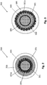
- FIG. 1 an embodiment of a power cable according to the present disclosure is schematically depicted, in a cross-section transversal to the longitudinal axis of the power cable.
- the power cable 100 comprises, in radial succession from the innermost part (cable longitudinal axis) towards the outside: a cooling duct 101 that extends along the cable length and that, in use, is intended to be run through by a cooling fluid 102; a carbon allotrope layer 104, an electrical conductor 103; an electrical insulation layer 105 and a cable jacket 106.
- the cooling duct 101 is connected, at both ends of the power cable 100, to a cooling fluid circulation system known per se and not shown nor described in greater detail.
- the electrical conductor 103 can be in form of threads of stranded wires 103c wound around the cooling duct 101 to form an electrically conductive layer.
- the electrical conductor 103 is made, for example, from copper, aluminum or alloys containing them.
- the carbon allotrope layer 104 can for example be made of graphene or a layer of carbon nanotubes (CNTs).
- the carbon allotrope layer 104 can be a layer applied onto each wire 103c strand of the electrical conductor 103 by means of a Chemical Vapor Deposition (CVD) process, or as a paint.
- the application of the carbon allotrope layer 104 can be before or after the wires 103c are stranded, in the latter case the application by paint being selected.
- the carbon allotrope layer 104 can be applied to the outer surface of the cooling duct 101.
- An electrical insulation layer 105 surrounds, in direct contact with, the electrical conductor 103.
- the electrical insulation layer 105 is made, for example, of optionally crosslinked polyethylene, of ethylene propylene rubber (EPR) or of polyvinylchloride (PVC).
- the cable jacket 106 can be made, for example, of PVC, polyurethane or polyethylene.
- the power cable of the present disclosure can include more than one electrical conductor, e.g. two, three or four electrical conductors.
- Fig. 1A depicts an example of a power cable 100a, which is a flat cable, comprising two electrical conductors 103a.
- each electrical conductor 103a may surround a respective cooling duct 101a, with the interposition of a carbon allotrope layer 104a.
- both the conductors 103a and the carbon allotrope layer 104a are schematically depicted, but they are meant to have structure and arrangement as described in connection with Fig. 1 .
- Each electrical conductor 103a is surrounded by a respective electrical insulation layer 105a. All the electrically insulated electrical conductors 103a, 105a are surrounded by a cable jacket 106a.
- the materials and forms of cable 100a components are analogous to those of cable 100.
- Fig. 2 schematically depicts another embodiment of a power cable according to the present disclosure, in a cross-section transversal to the longitudinal axis of the power cable.
- the power cable 200 comprises, in radial succession from the innermost part towards the outside: an electrical conductor 203 surrounded by a carbon allotrope layer 204 (also in this case, both the electrical conductor 203 and the carbon allotrope layer 204 are schematically depicted for clarity sake, but they are meant to have structure and arrangement as described in connection with Fig. 1 ), a cooling duct 201 that, in use, is intended to be run through a cooling fluid (not shown, for clarity sake), an electrical insulation layer 205 and a cable jacket 206.
- the electrical conductor 203 can be in form of a solid rod or of threads of stranded wires (as depicted in Fig.1 ).
- the electrical conductor 203 either solid or in strands, is made, for example, of copper, aluminum alloys containing them.
- the layer 204 of carbon allotrope is applied peripherally to the solid conductor 203, to the external surface thereof.
- the cooling duct 201 is in form of a plurality of cooling tubes 201a circumferentially stranded around the electrical conductor 203 to form a layer. As in the embodiment of Fig. 1 , the cooling duct 201 is connected, at both ends of the power cable 200, to a cooling fluid circulation system known per se and not shown nor described in greater detail.
- the cooling duct 201 is surrounded by an electrically insulation layer 205 which, in turn, is surrounded by a cable jacket 206.
- a power cable with the configuration of cable 200 can include more than one electrical conductor, e.g. two or three electrical conductors.
- each electrical conductor can be surrounded by a respective cooling duct like the cooling duct 201, with the interposition of a carbon allotrope layer.
- Each plurality of cooling ducts is surrounded by a respective electrical insulation layer. All the electrical insulation layers are surrounded by a single cable jacket like the cable jacket 206.
- Fig. 3 schematically depicts still another embodiment of a power cable according to the present disclosure, in a cross-section transversal to the longitudinal axis of the power cable.
- the power cable 300 comprises, in radial succession from the innermost part towards the outside: an electrical conductor 303 surrounded by a carbon allotrope layer 304 (also in this case, both the conductors 203 and the carbon allotrope layer 204 are schematically depicted for clarity sake, but they are meant to have structure and arrangement as described in connection with Fig. 1 ); an electrical insulation layer 305; a cooling duct 301 that, in use, is intended to be run through a cooling fluid (not shown, for clarity sake) and a cable jacket 306.
- the electrical conductor 303 and the carbon allotrope layer 304 can have the form and material as described in connection with, respectively, the electrical conductor 203 of Fig. 2 and 103 of Fig. 1 and the carbon allotrope layer 204 of Fig. 2 and 104 of Fig. 1 .
- the cooling duct 301 is in form of a plurality of cooling tubes 301a circumferentially stranded around the electrically insulation layer 305. As in the embodiments of Figs. 1 and 2 , the cooling duct 301 is connected, at end of the power cable 300, to a cooling fluid circulation system known per se and not shown nor described in greater detail.
- the electrically insulation layer 305 is surrounded by a cooling duct in form of two tubes or layers with different diameters which, in operation, are substantially concentric and run through by a cooling fluid.
- a power cable with the configuration of cable 300 can include more than one electrical conductor, e.g. two or three electrical conductors.
- each electrical conductor is surrounded by a respective layer of electrically insulation layer, with the interposition of a carbon allotrope layer.
- Each electrically insulation layer is surrounded by a respective cooling duct like the cooling duct 301. All the cooling ducts are surrounded by a single cable jacket like the cable jacket 306.
Landscapes
- Insulated Conductors (AREA)
Abstract
Description
- The present disclosure relates to the technical field of power cables. Specifically, the present disclosure relates to a power cable with enhanced ampacity.
- Ampacity (also described as current-carrying capacity) is defined as the maximum current, in amperes, that an electrical conductor can carry continuously under the conditions of use without exceeding its temperature rating.
- The ampacity of an electrical conductor depends on its ability to dissipate heat without damage to the electrical conductor or its electrical insulation. This ability to dissipate heat is a function of the temperature rating of the cable electrical insulation material, the electrical resistance of the electrical conductor material, the ambient temperature.
- Most power cable is sized according to its ampacity. Excessive current can cause overheating, insulation damage and fire/shock hazards that, in turn, can harm equipment through heat buildup and produce cable faults that lead to lost productivity..
- An emerging application of power cables is in the field of electrical vehicles (EV), which are expected to nearly replace, in the next years, traditional vehicles powered by internal combustion engines.
- Since the EV market is becoming a reality, a lot of services accessories to the common use of such vehicles need to be developed to satisfy the users. A critical aspect is charging the EV batteries: in this context, the availability of EV batteries charging stations that allow time saving for a (complete or partial) battery charge cycle is essential.
- To make an EV battery charge faster, a possibility is to increase the power of the charging stations and the energy transferred through power cables. Nowadays, charging stations can have a power higher than 350 kW.
- Electrical power P is, as known, defined by Ohm's law as P = RI2 = VI, where R denotes the electrical resistance of an electrical conductor, I denotes the electrical current flowing through the electrical conductor and V denotes the electrical potential difference between two ends of the electrical conductor (voltage).
- Since the electrical resistance is a material-dependent parameter, affected by resistivity and the geometry of the system, to increase the voltage means, in short, increasing the cross-section of the electrical conductor, resulting in a power cable which is significantly heavy and difficult to handle. However, light weight and ease of handling are seen as essential for power cables for EV batteries charging stations.
- Another possibility to increase the electrical power delivered by an electrical conductor is to increase the current rate. This, as known by Joule's law, results in a significant increase of temperature by Joule's effect.
- To overcome this issue, power cable cooling systems have been proposed to attenuate rising temperature in the power cable, affecting, inter alia, the properties of the insulation around it.
-
US 9,449,739 - The Applicant has perceived that there is a strong need for power cables featuring increased ampacity. Such a need is particularly felt in the field of power cables for EV batteries charging stations: these power cables, in addition to high ampacity, should at the same time feature light weight and be easy to handle.
- In respect of
US 9,449,739 - An object of the present disclosure is to provide a power cable which is more efficiently cooled during operation.
- Power cables endowed of a cooling system comprising a cooling duct extended along the electric conductor within a common cable jacket are known in the art. See, for example,
WO 2018/104234 andWO 2015/119791 . The addition of a cooling duct within the cable jacket increases the cable diameter. As the mass flow rate of the cooling fluid is to be suitable for attaining a suitable cooling of the electric conductor, the just mentioned patent applications, relating to power cables for EV charging, provides for a plurality of cooling ducts resulting in a complex cable structure and, accordingly, a complex manufacturing and cable cost increasing. - The Applicant found that the cooling efficiency of a cooling system for power cable comprising a cooling duct extended along the electric conductor within a common cable jacket could be increased by providing the power cable with a layer of carbon allotrope extended along the electric conductor, in direct contact thereto and interposed between the electric conductor and the cooling system .
- According to the present disclosure, a power cable is provided comprising a cable jacket enclosing:
- an electric conductor;
- an electrical insulation layer surrounding the electrical conductor;
- a cooling system comprising a cooling duct substantially parallel to the electrical conductor along a power cable longitudinal axis and designed to be, in use, run through by a cooling fluid; and
- a carbon allotrope layer in direct contact with the electrical conductor;
- In an embodiment, the cooling duct is provided in a radial inner position with respect to the electrical conductor and at least partially in direct contact with a carbon allotrope layer. In this case, the electrical insulation layer is in contact with the electric conductor, with a carbon allotrope layer optionally interposed.
- In another embodiment, the cooling duct is provided in a radial outer position with respect to the electrical conductor. In this embodiment, the cooling duct can be in form of a plurality of cooling tubes.
- When the cooling duct is provided in a radial outer position with respect to the electrical conductor, the cooling duct can be in a radial inner position with respect to the electrical insulation layer, thus separating the electrical insulation layer from the electrical conductor. In this case, the cooling duct is at least partially in direct contact with a carbon allotrope layer.
- Alternatively, when the cooling duct is provided in a radial outer position with respect to the electrical conductor, the cooling duct can be in a radial outer position with respect to the electrical insulation layer, too. In this case, the electrical insulation layer is in contact with the electric conductor, with a carbon allotrope layer optionally interposed, and separates the cooling duct from the electric conductor and the carbon allotrope layer.
- The power cable of the present disclosure can comprise a plurality of electric conductors, for example from two to four electric conductors.
- The carbon allotrope layer can be, for example, a layer of graphene, of graphite (e.g. pyrolytic graphite) or a layer of carbon nanotubes (CNTs). Graphene is an allotrope (form) of carbon consisting of a single layer of carbon atoms arranged in a hexagonal lattice. Carbon nanotubes (CNTs) are allotropes of carbon with a cylindrical nanostructure.
- The carbon allotrope layer can have a thickness of some microns, for example a thickness in the range from 5 µm to 100 µm.
- The provision of the carbon allotrope layer interposed between the conductor and the cooling system enhances the transmission of heat from the electrical conductor to the cooling system. Thus, the provision of the carbon allotrope layer helps, in use, the cooling of the electrical conductor of the power cable and thus allows higher electrical current flow without the risk of exceeding the temperature ratings. Thanks to this, the provision of the carbon allotrope layer improves the power cable ampacity, i.e. the maximum current that the cable conductor can carry continuously under the conditions of use without exceeding its temperature rating. The performance of the power cable is consequently increased.
- For the purpose of the present description and of the appended claims, except where otherwise indicated, all numbers expressing amounts, quantities, percentages, and so forth, are to be understood as being modified in all instances by the term "about". Also, all ranges include any combination of the maximum and minimum points disclosed and include any intermediate ranges therein, which may or may not be specifically enumerated herein.
- For the purpose of the present description and of the appended claims, the words "a" or "an" should be read to include one or at least one and the singular also includes the plural unless it is obvious that it is meant otherwise. This is done merely for convenience and to give a general sense of the invention.
- The present disclosure, in at least one of the aforementioned aspects, can be implemented according to one or more of the following embodiments, optionally combined together.
- The preceding summary is to provide an understanding of some aspects of the disclosure. As will be appreciated, other embodiments of the disclosure are possible utilizing, alone or in combination, one or more of the features set forth above or described in detail below.
- The features and advantages of a power cable according to the present disclosure will be made even clearer by the following detailed description of exemplary and non-limitative embodiments. For its better intelligibility, the following detailed description should preferably be read making reference to the attached drawings, wherein:
-
Fig. 1 shows, in a cross-section transversal to a longitudinal axis, a power cable according to an embodiment of the present disclosure; -
Fig. 1A shows a cable according to the embodiment ofFig. 1 including two electrical conductors; -
Fig. 2 shows, in a cross-section transversal to a longitudinal axis, a power cable according to another embodiment of the present disclosure, and -
Fig. 3 shows, in a cross-section transversal to a longitudinal axis, a power cable according to still another embodiment of the present disclosure. - The present disclosure relates to a power cable comprising a cable jacket enclosing at least one electrical conductor, an electrical insulation layer, a carbon allotrope layer and a cooling system comprising at least one duct substantially parallel to the electrical conductor along the cable length and designed to be, in use, run through by a cooling fluid.
- As cooling fluid glycol or glycol mixture employed in air-cooling system can be used.
- The electrical conductor is in direct contact with the carbon allotrope layer. The carbon allotrope layer is interposed between the conductor and at least one duct of the cooling system .
- The at least one cooling duct can be provided:
- a) in a radial inner position with respect to the conductor, as in the embodiment depicted in
Figs. 1 and Fig. 1A , or, alternatively - b) in a radial outer position with respect to the electrical conductor and in a radial inner position with respect to the electrical insulation layer, as in the embodiment depicted in
Fig. 2 , and/or - c) in a radial outer position with respect to the electrical insulation layer, as in the embodiment depicted in
Fig. 3 . - Referring to
Fig. 1 , an embodiment of a power cable according to the present disclosure is schematically depicted, in a cross-section transversal to the longitudinal axis of the power cable. - The
power cable 100 comprises, in radial succession from the innermost part (cable longitudinal axis) towards the outside: a coolingduct 101 that extends along the cable length and that, in use, is intended to be run through by a coolingfluid 102; acarbon allotrope layer 104, anelectrical conductor 103; anelectrical insulation layer 105 and acable jacket 106. - The cooling
duct 101 is connected, at both ends of thepower cable 100, to a cooling fluid circulation system known per se and not shown nor described in greater detail. - The
electrical conductor 103 can be in form of threads of strandedwires 103c wound around the coolingduct 101 to form an electrically conductive layer. Theelectrical conductor 103 is made, for example, from copper, aluminum or alloys containing them. - The
carbon allotrope layer 104 can for example be made of graphene or a layer of carbon nanotubes (CNTs). - The
carbon allotrope layer 104 can be a layer applied onto eachwire 103c strand of theelectrical conductor 103 by means of a Chemical Vapor Deposition (CVD) process, or as a paint. The application of thecarbon allotrope layer 104 can be before or after thewires 103c are stranded, in the latter case the application by paint being selected. - Alternatively, or in addition, the
carbon allotrope layer 104 can be applied to the outer surface of the coolingduct 101. - An
electrical insulation layer 105 surrounds, in direct contact with, theelectrical conductor 103. Theelectrical insulation layer 105 is made, for example, of optionally crosslinked polyethylene, of ethylene propylene rubber (EPR) or of polyvinylchloride (PVC). - The
cable jacket 106 can be made, for example, of PVC, polyurethane or polyethylene. - The power cable of the present disclosure can include more than one electrical conductor, e.g. two, three or four electrical conductors.
Fig. 1A depicts an example of apower cable 100a, which is a flat cable, comprising twoelectrical conductors 103a. In such a case, eachelectrical conductor 103a may surround arespective cooling duct 101a, with the interposition of acarbon allotrope layer 104a. For clarity sake, both theconductors 103a and thecarbon allotrope layer 104a are schematically depicted, but they are meant to have structure and arrangement as described in connection withFig. 1 . - Each
electrical conductor 103a is surrounded by a respectiveelectrical insulation layer 105a. All the electrically insulatedelectrical conductors cable jacket 106a. The materials and forms ofcable 100a components are analogous to those ofcable 100. -
Fig. 2 schematically depicts another embodiment of a power cable according to the present disclosure, in a cross-section transversal to the longitudinal axis of the power cable. - In this embodiment the
power cable 200 comprises, in radial succession from the innermost part towards the outside: anelectrical conductor 203 surrounded by a carbon allotrope layer 204 (also in this case, both theelectrical conductor 203 and thecarbon allotrope layer 204 are schematically depicted for clarity sake, but they are meant to have structure and arrangement as described in connection withFig. 1 ), a coolingduct 201 that, in use, is intended to be run through a cooling fluid (not shown, for clarity sake), anelectrical insulation layer 205 and acable jacket 206. - The
electrical conductor 203 can be in form of a solid rod or of threads of stranded wires (as depicted inFig.1 ). Theelectrical conductor 203, either solid or in strands, is made, for example, of copper, aluminum alloys containing them. In case theelectrical conductor 203 is a single solid conductor, thelayer 204 of carbon allotrope is applied peripherally to thesolid conductor 203, to the external surface thereof. - The cooling
duct 201 is in form of a plurality ofcooling tubes 201a circumferentially stranded around theelectrical conductor 203 to form a layer. As in the embodiment ofFig. 1 , the coolingduct 201 is connected, at both ends of thepower cable 200, to a cooling fluid circulation system known per se and not shown nor described in greater detail. - The cooling
duct 201 is surrounded by anelectrically insulation layer 205 which, in turn, is surrounded by acable jacket 206. - A power cable with the configuration of
cable 200 can include more than one electrical conductor, e.g. two or three electrical conductors. In such a case, each electrical conductor can be surrounded by a respective cooling duct like the coolingduct 201, with the interposition of a carbon allotrope layer. Each plurality of cooling ducts is surrounded by a respective electrical insulation layer. All the electrical insulation layers are surrounded by a single cable jacket like thecable jacket 206. -
Fig. 3 schematically depicts still another embodiment of a power cable according to the present disclosure, in a cross-section transversal to the longitudinal axis of the power cable. - In this embodiment the
power cable 300 comprises, in radial succession from the innermost part towards the outside: anelectrical conductor 303 surrounded by a carbon allotrope layer 304 (also in this case, both theconductors 203 and thecarbon allotrope layer 204 are schematically depicted for clarity sake, but they are meant to have structure and arrangement as described in connection withFig. 1 ); anelectrical insulation layer 305; a coolingduct 301 that, in use, is intended to be run through a cooling fluid (not shown, for clarity sake) and acable jacket 306. - The
electrical conductor 303 and thecarbon allotrope layer 304 can have the form and material as described in connection with, respectively, theelectrical conductor 203 ofFig. 2 and 103 ofFig. 1 and thecarbon allotrope layer 204 ofFig. 2 and 104 ofFig. 1 . - The cooling
duct 301 is in form of a plurality ofcooling tubes 301a circumferentially stranded around theelectrically insulation layer 305. As in the embodiments ofFigs. 1 and2 , the coolingduct 301 is connected, at end of thepower cable 300, to a cooling fluid circulation system known per se and not shown nor described in greater detail. - In an alternative embodiment, not shown, the
electrically insulation layer 305 is surrounded by a cooling duct in form of two tubes or layers with different diameters which, in operation, are substantially concentric and run through by a cooling fluid. - A power cable with the configuration of
cable 300 can include more than one electrical conductor, e.g. two or three electrical conductors. In such a case, each electrical conductor is surrounded by a respective layer of electrically insulation layer, with the interposition of a carbon allotrope layer. Each electrically insulation layer is surrounded by a respective cooling duct like the coolingduct 301. All the cooling ducts are surrounded by a single cable jacket like thecable jacket 306.
Claims (9)
- A power cable (100;100a;200;300) comprising a cable jacket (106;106a;206;306) enclosing;- an electric conductor (103,103a,103c;203;303);- an electrical insulation layer (105;105a;205;305) surrounding the electrical conductor (103,103a,103c;203;303);- a cooling system comprising a cooling duct (101;101a;201;301) substantially parallel to the electrical conductor (103,103a,103c;203;303) along a power cable longitudinal axis and designed to be, in use, run through by a cooling fluid (102;102a); and- a carbon allotrope layer (104;104a;204;304) in direct contact with the electrical conductor (103,103a,103c;203;303),wherein the carbon allotrope layer (104;104a;204;304) is provided between the electric conductor (103,103a,103c;203;303) and the cooling duct.
- The power cable (100;100a) of claim 1, wherein the cooling duct (101;101a) is provided in a radial inner position with respect to the electrical conductor (103,103a,103c).
- The power cable (200;300) of claim 1, wherein the cooling duct (201,301) is provided in a radial outer position with respect to the electrical conductor (203;303).
- The power cable (200;300) of claim 3, wherein the cooling duct (201,301) is in form of plurality of cooling tubes (201a,301a).
- The power cable (200) of claim 3, wherein the cooling duct (201) is provided in a radial inner position with respect to the electrical insulation layer (205) and separates the electrically insulation layer (205) from the electrical conductor (203).
- The power cable (100;100a;200;300) of claim 1, wherein the carbon allotrope layer (104;104a;204;304) is a layer made of graphene, graphite and carbon nanotubes (CNTs).
- The power cable (200;300) of claim 1, wherein the electrical conductor (203;303) comprises a single solid conductor.
- The power cable (100;100a;200;300) of claim 1, wherein the electrical conductor (103;203;303) comprises threads of stranded wires (103c).
- The power cable (100a;200;300) of claim 1 comprising a plurality of electric conductors (103a,203;303).
Applications Claiming Priority (1)
| Application Number | Priority Date | Filing Date | Title |
|---|---|---|---|
| IT201900007142 | 2019-05-23 |
Publications (3)
| Publication Number | Publication Date |
|---|---|
| EP3742458A1 true EP3742458A1 (en) | 2020-11-25 |
| EP3742458B1 EP3742458B1 (en) | 2024-08-28 |
| EP3742458C0 EP3742458C0 (en) | 2024-08-28 |
Family
ID=67876019
Family Applications (1)
| Application Number | Title | Priority Date | Filing Date |
|---|---|---|---|
| EP20175760.6A Active EP3742458B1 (en) | 2019-05-23 | 2020-05-20 | Power cable with enhanced ampacity |
Country Status (6)
| Country | Link |
|---|---|
| US (1) | US10964450B2 (en) |
| EP (1) | EP3742458B1 (en) |
| AU (1) | AU2020203147B2 (en) |
| ES (1) | ES3004062T3 (en) |
| NZ (1) | NZ764449A (en) |
| PL (1) | PL3742458T3 (en) |
Families Citing this family (6)
| Publication number | Priority date | Publication date | Assignee | Title |
|---|---|---|---|---|
| US11935671B2 (en) * | 2021-01-27 | 2024-03-19 | Apple Inc. | Spiral wound conductor for high current applications |
| CN113205910B (en) * | 2021-05-25 | 2024-10-22 | 上海飞航电线电缆有限公司 | Intelligent charging pile cable and preparation method |
| EP4125099A1 (en) * | 2021-07-30 | 2023-02-01 | Aptiv Technologies Limited | A power cable assembly for a power distribution system having an integrated cooling system |
| EP4125100A1 (en) * | 2021-07-30 | 2023-02-01 | Aptiv Technologies Limited | A power cable assembly for a power distribution system having an integrated cooling system |
| EP4147903A1 (en) * | 2021-09-14 | 2023-03-15 | ABB E-mobility B.V. | Charging cable for charging an electric vehicle, and electric vehicle supply equipment with a charging cable |
| TWI884673B (en) | 2024-01-03 | 2025-05-21 | 財團法人工業技術研究院 | Heat dissipation structure for cable and heat dissipation method for the same |
Citations (6)
| Publication number | Priority date | Publication date | Assignee | Title |
|---|---|---|---|---|
| US3962529A (en) * | 1970-10-07 | 1976-06-08 | Sumitomo Electric Industries, Ltd. | Evaporative cooling power cable line |
| GB2350474A (en) * | 1999-05-28 | 2000-11-29 | Asea Brown Boveri | A flexible power cable |
| US20020153162A1 (en) * | 2000-12-27 | 2002-10-24 | Sergio Spreafico | Superconducting cable |
| WO2015119791A1 (en) | 2014-02-05 | 2015-08-13 | Tesla Motors, Inc. | Cooling of charging cable |
| US9449739B2 (en) | 2012-10-16 | 2016-09-20 | The Boeing Company | High power, high frequency power cable |
| WO2018104234A1 (en) | 2016-12-05 | 2018-06-14 | Leoni Kabel Gmbh | High-current cable and power supply system with high-current cable |
Family Cites Families (12)
| Publication number | Priority date | Publication date | Assignee | Title |
|---|---|---|---|---|
| US3949154A (en) * | 1973-08-02 | 1976-04-06 | Felten & Guilleaume Kabelwerke Ag | Internally cooled high-voltage high-energy cable |
| IT1161893B (en) * | 1983-02-14 | 1987-03-18 | Pirelli Cavi Spa | MULTI-POLE CABLE WITH FLUID OIL |
| US5412304A (en) * | 1993-08-09 | 1995-05-02 | Hughes Aircraft Company | Cooled primary of automobile battery charging transformer |
| US5591937A (en) * | 1994-12-02 | 1997-01-07 | Hughes Aircraft Company | High power, high frequency transmission cable breach detection |
| US6730851B2 (en) * | 2000-10-06 | 2004-05-04 | Pirelli Cavi E Sistemi S.P.A. | Superconducting cable and current transmission and/or distribution network including the superconducting cable |
| KR101709368B1 (en) * | 2009-07-16 | 2017-02-22 | 쓰리엠 이노베이티브 프로퍼티즈 컴파니 | Submersible composite cable and methods |
| WO2012051510A2 (en) * | 2010-10-14 | 2012-04-19 | Gregory Thomas Mark | Actively cooled electrical connection |
| WO2012079631A1 (en) * | 2010-12-15 | 2012-06-21 | Abb Technology Ag | High voltage electric cable |
| JP2013140764A (en) * | 2011-12-06 | 2013-07-18 | Sumitomo Electric Ind Ltd | Superconducting cable, superconducting cable line, method for laying superconducting cable, and method for operating superconducting cable line |
| DE102015120048A1 (en) * | 2015-11-19 | 2017-05-24 | Dr. Ing. H.C. F. Porsche Aktiengesellschaft | Electrical line arrangement |
| US12191228B2 (en) * | 2016-04-06 | 2025-01-07 | Sanctioned Risk Solutions, Inc. | Heat dissipation using nanoscale materials |
| DE102018102207A1 (en) * | 2018-02-01 | 2019-08-01 | Dr. Ing. H.C. F. Porsche Aktiengesellschaft | Vehicle charging cable |
-
2020
- 2020-05-14 AU AU2020203147A patent/AU2020203147B2/en active Active
- 2020-05-14 NZ NZ764449A patent/NZ764449A/en unknown
- 2020-05-20 ES ES20175760T patent/ES3004062T3/en active Active
- 2020-05-20 EP EP20175760.6A patent/EP3742458B1/en active Active
- 2020-05-20 PL PL20175760.6T patent/PL3742458T3/en unknown
- 2020-05-21 US US16/880,822 patent/US10964450B2/en active Active
Patent Citations (6)
| Publication number | Priority date | Publication date | Assignee | Title |
|---|---|---|---|---|
| US3962529A (en) * | 1970-10-07 | 1976-06-08 | Sumitomo Electric Industries, Ltd. | Evaporative cooling power cable line |
| GB2350474A (en) * | 1999-05-28 | 2000-11-29 | Asea Brown Boveri | A flexible power cable |
| US20020153162A1 (en) * | 2000-12-27 | 2002-10-24 | Sergio Spreafico | Superconducting cable |
| US9449739B2 (en) | 2012-10-16 | 2016-09-20 | The Boeing Company | High power, high frequency power cable |
| WO2015119791A1 (en) | 2014-02-05 | 2015-08-13 | Tesla Motors, Inc. | Cooling of charging cable |
| WO2018104234A1 (en) | 2016-12-05 | 2018-06-14 | Leoni Kabel Gmbh | High-current cable and power supply system with high-current cable |
Also Published As
| Publication number | Publication date |
|---|---|
| US10964450B2 (en) | 2021-03-30 |
| EP3742458B1 (en) | 2024-08-28 |
| US20200373038A1 (en) | 2020-11-26 |
| ES3004062T3 (en) | 2025-03-11 |
| PL3742458T3 (en) | 2025-01-07 |
| AU2020203147B2 (en) | 2025-05-15 |
| EP3742458C0 (en) | 2024-08-28 |
| NZ764449A (en) | 2026-01-30 |
| AU2020203147A1 (en) | 2020-12-10 |
Similar Documents
| Publication | Publication Date | Title |
|---|---|---|
| EP3742458B1 (en) | Power cable with enhanced ampacity | |
| CN103262177B (en) | High voltage electric cable | |
| JP5984440B2 (en) | Coaxial wire manufacturing method | |
| CN114342009A (en) | Electric vehicle charging cable | |
| US20140102755A1 (en) | Communications Cables Having Electrically Insulative but Thermally Conductive Cable Jackets | |
| JP2022547151A (en) | electric car charging cable | |
| JP6408619B2 (en) | Power supply cable and power supply cable with connector | |
| KR20120105843A (en) | Power cable for high frequency | |
| CN1244284A (en) | Method and device for manufacturing transformer/reactor | |
| CN115810448A (en) | Charging cable for charging electric vehicle and electric vehicle power supply equipment with charging cable | |
| US20180184487A1 (en) | Shielded Fluoropolymer Wire for High Temperature Skin Effect Trace Heating | |
| WO2024149339A1 (en) | Liquid-cooled cable | |
| JP6554023B2 (en) | Internal cooling cable | |
| JP2024505057A (en) | Non-fluid cooled electric vehicle fast charging cable | |
| CN204857213U (en) | An aluminum core high temperature and high voltage resistant shielded cable for electric vehicles | |
| US10959295B2 (en) | Shielded wire for high voltage skin effect trace heating | |
| CN114843023A (en) | Charging cables and charging piles | |
| US11935671B2 (en) | Spiral wound conductor for high current applications | |
| CN116072334A (en) | Wire and cable | |
| JP2006066135A (en) | Multi-core cable | |
| JP4676095B2 (en) | Superconducting cable | |
| CN217767853U (en) | Light cable with reduced diameter | |
| CN219497405U (en) | High-power charging wire of electric automobile | |
| US20250222801A1 (en) | Lower loss charging cable | |
| US12617302B2 (en) | Fast charge device for an electric or hybrid vehicle |
Legal Events
| Date | Code | Title | Description |
|---|---|---|---|
| PUAI | Public reference made under article 153(3) epc to a published international application that has entered the european phase |
Free format text: ORIGINAL CODE: 0009012 |
|
| STAA | Information on the status of an ep patent application or granted ep patent |
Free format text: STATUS: THE APPLICATION HAS BEEN PUBLISHED |
|
| AK | Designated contracting states |
Kind code of ref document: A1 Designated state(s): AL AT BE BG CH CY CZ DE DK EE ES FI FR GB GR HR HU IE IS IT LI LT LU LV MC MK MT NL NO PL PT RO RS SE SI SK SM TR |
|
| AX | Request for extension of the european patent |
Extension state: BA ME |
|
| STAA | Information on the status of an ep patent application or granted ep patent |
Free format text: STATUS: REQUEST FOR EXAMINATION WAS MADE |
|
| 17P | Request for examination filed |
Effective date: 20210510 |
|
| RBV | Designated contracting states (corrected) |
Designated state(s): AL AT BE BG CH CY CZ DE DK EE ES FI FR GB GR HR HU IE IS IT LI LT LU LV MC MK MT NL NO PL PT RO RS SE SI SK SM TR |
|
| STAA | Information on the status of an ep patent application or granted ep patent |
Free format text: STATUS: EXAMINATION IS IN PROGRESS |
|
| 17Q | First examination report despatched |
Effective date: 20210716 |
|
| GRAP | Despatch of communication of intention to grant a patent |
Free format text: ORIGINAL CODE: EPIDOSNIGR1 |
|
| STAA | Information on the status of an ep patent application or granted ep patent |
Free format text: STATUS: GRANT OF PATENT IS INTENDED |
|
| INTG | Intention to grant announced |
Effective date: 20240320 |
|
| GRAS | Grant fee paid |
Free format text: ORIGINAL CODE: EPIDOSNIGR3 |
|
| GRAA | (expected) grant |
Free format text: ORIGINAL CODE: 0009210 |
|
| STAA | Information on the status of an ep patent application or granted ep patent |
Free format text: STATUS: THE PATENT HAS BEEN GRANTED |
|
| AK | Designated contracting states |
Kind code of ref document: B1 Designated state(s): AL AT BE BG CH CY CZ DE DK EE ES FI FR GB GR HR HU IE IS IT LI LT LU LV MC MK MT NL NO PL PT RO RS SE SI SK SM TR |
|
| REG | Reference to a national code |
Ref country code: CH Ref legal event code: EP |
|
| REG | Reference to a national code |
Ref country code: DE Ref legal event code: R096 Ref document number: 602020036520 Country of ref document: DE |
|
| REG | Reference to a national code |
Ref country code: IE Ref legal event code: FG4D |
|
| U01 | Request for unitary effect filed |
Effective date: 20240828 |
|
| U07 | Unitary effect registered |
Designated state(s): AT BE BG DE DK EE FI FR IT LT LU LV MT NL PT RO SE SI Effective date: 20240906 |
|
| PG25 | Lapsed in a contracting state [announced via postgrant information from national office to epo] |
Ref country code: NO Free format text: LAPSE BECAUSE OF FAILURE TO SUBMIT A TRANSLATION OF THE DESCRIPTION OR TO PAY THE FEE WITHIN THE PRESCRIBED TIME-LIMIT Effective date: 20241128 |
|
| PG25 | Lapsed in a contracting state [announced via postgrant information from national office to epo] |
Ref country code: GR Free format text: LAPSE BECAUSE OF FAILURE TO SUBMIT A TRANSLATION OF THE DESCRIPTION OR TO PAY THE FEE WITHIN THE PRESCRIBED TIME-LIMIT Effective date: 20241129 |
|
| PG25 | Lapsed in a contracting state [announced via postgrant information from national office to epo] |
Ref country code: IS Free format text: LAPSE BECAUSE OF FAILURE TO SUBMIT A TRANSLATION OF THE DESCRIPTION OR TO PAY THE FEE WITHIN THE PRESCRIBED TIME-LIMIT Effective date: 20241228 |
|
| PG25 | Lapsed in a contracting state [announced via postgrant information from national office to epo] |
Ref country code: HR Free format text: LAPSE BECAUSE OF FAILURE TO SUBMIT A TRANSLATION OF THE DESCRIPTION OR TO PAY THE FEE WITHIN THE PRESCRIBED TIME-LIMIT Effective date: 20240828 |
|
| PG25 | Lapsed in a contracting state [announced via postgrant information from national office to epo] |
Ref country code: RS Free format text: LAPSE BECAUSE OF FAILURE TO SUBMIT A TRANSLATION OF THE DESCRIPTION OR TO PAY THE FEE WITHIN THE PRESCRIBED TIME-LIMIT Effective date: 20241128 |
|
| PG25 | Lapsed in a contracting state [announced via postgrant information from national office to epo] |
Ref country code: RS Free format text: LAPSE BECAUSE OF FAILURE TO SUBMIT A TRANSLATION OF THE DESCRIPTION OR TO PAY THE FEE WITHIN THE PRESCRIBED TIME-LIMIT Effective date: 20241128 Ref country code: NO Free format text: LAPSE BECAUSE OF FAILURE TO SUBMIT A TRANSLATION OF THE DESCRIPTION OR TO PAY THE FEE WITHIN THE PRESCRIBED TIME-LIMIT Effective date: 20241128 Ref country code: IS Free format text: LAPSE BECAUSE OF FAILURE TO SUBMIT A TRANSLATION OF THE DESCRIPTION OR TO PAY THE FEE WITHIN THE PRESCRIBED TIME-LIMIT Effective date: 20241228 Ref country code: HR Free format text: LAPSE BECAUSE OF FAILURE TO SUBMIT A TRANSLATION OF THE DESCRIPTION OR TO PAY THE FEE WITHIN THE PRESCRIBED TIME-LIMIT Effective date: 20240828 Ref country code: GR Free format text: LAPSE BECAUSE OF FAILURE TO SUBMIT A TRANSLATION OF THE DESCRIPTION OR TO PAY THE FEE WITHIN THE PRESCRIBED TIME-LIMIT Effective date: 20241129 |
|
| REG | Reference to a national code |
Ref country code: ES Ref legal event code: FG2A Ref document number: 3004062 Country of ref document: ES Kind code of ref document: T3 Effective date: 20250311 |
|
| PG25 | Lapsed in a contracting state [announced via postgrant information from national office to epo] |
Ref country code: SM Free format text: LAPSE BECAUSE OF FAILURE TO SUBMIT A TRANSLATION OF THE DESCRIPTION OR TO PAY THE FEE WITHIN THE PRESCRIBED TIME-LIMIT Effective date: 20240828 |
|
| PG25 | Lapsed in a contracting state [announced via postgrant information from national office to epo] |
Ref country code: CZ Free format text: LAPSE BECAUSE OF FAILURE TO SUBMIT A TRANSLATION OF THE DESCRIPTION OR TO PAY THE FEE WITHIN THE PRESCRIBED TIME-LIMIT Effective date: 20240828 |
|
| PG25 | Lapsed in a contracting state [announced via postgrant information from national office to epo] |
Ref country code: SK Free format text: LAPSE BECAUSE OF FAILURE TO SUBMIT A TRANSLATION OF THE DESCRIPTION OR TO PAY THE FEE WITHIN THE PRESCRIBED TIME-LIMIT Effective date: 20240828 |
|
| U20 | Renewal fee for the european patent with unitary effect paid |
Year of fee payment: 6 Effective date: 20250527 |
|
| PLBE | No opposition filed within time limit |
Free format text: ORIGINAL CODE: 0009261 |
|
| STAA | Information on the status of an ep patent application or granted ep patent |
Free format text: STATUS: NO OPPOSITION FILED WITHIN TIME LIMIT |
|
| PGFP | Annual fee paid to national office [announced via postgrant information from national office to epo] |
Ref country code: PL Payment date: 20250508 Year of fee payment: 6 |
|
| PGFP | Annual fee paid to national office [announced via postgrant information from national office to epo] |
Ref country code: GB Payment date: 20250527 Year of fee payment: 6 Ref country code: ES Payment date: 20250602 Year of fee payment: 6 |
|
| 26N | No opposition filed |
Effective date: 20250530 |
|
| REG | Reference to a national code |
Ref country code: CH Ref legal event code: H13 Free format text: ST27 STATUS EVENT CODE: U-0-0-H10-H13 (AS PROVIDED BY THE NATIONAL OFFICE) Effective date: 20251223 |
|
| PG25 | Lapsed in a contracting state [announced via postgrant information from national office to epo] |
Ref country code: CH Free format text: LAPSE BECAUSE OF NON-PAYMENT OF DUE FEES Effective date: 20250531 |
|
| PG25 | Lapsed in a contracting state [announced via postgrant information from national office to epo] |
Ref country code: MC Free format text: LAPSE BECAUSE OF FAILURE TO SUBMIT A TRANSLATION OF THE DESCRIPTION OR TO PAY THE FEE WITHIN THE PRESCRIBED TIME-LIMIT Effective date: 20240828 |
|
| PG25 | Lapsed in a contracting state [announced via postgrant information from national office to epo] |
Ref country code: IE Free format text: LAPSE BECAUSE OF NON-PAYMENT OF DUE FEES Effective date: 20250520 |