EP3742214A1 - Imaging lens and camera module comprising same - Google Patents
Imaging lens and camera module comprising same Download PDFInfo
- Publication number
- EP3742214A1 EP3742214A1 EP19741742.1A EP19741742A EP3742214A1 EP 3742214 A1 EP3742214 A1 EP 3742214A1 EP 19741742 A EP19741742 A EP 19741742A EP 3742214 A1 EP3742214 A1 EP 3742214A1
- Authority
- EP
- European Patent Office
- Prior art keywords
- lens
- lens group
- imaging lens
- imaging
- mode
- Prior art date
- Legal status (The legal status is an assumption and is not a legal conclusion. Google has not performed a legal analysis and makes no representation as to the accuracy of the status listed.)
- Granted
Links
Images




Classifications
-
- G—PHYSICS
- G02—OPTICS
- G02B—OPTICAL ELEMENTS, SYSTEMS OR APPARATUS
- G02B13/00—Optical objectives specially designed for the purposes specified below
- G02B13/001—Miniaturised objectives for electronic devices, e.g. portable telephones, webcams, PDAs, small digital cameras
- G02B13/0015—Miniaturised objectives for electronic devices, e.g. portable telephones, webcams, PDAs, small digital cameras characterised by the lens design
- G02B13/002—Miniaturised objectives for electronic devices, e.g. portable telephones, webcams, PDAs, small digital cameras characterised by the lens design having at least one aspherical surface
- G02B13/0035—Miniaturised objectives for electronic devices, e.g. portable telephones, webcams, PDAs, small digital cameras characterised by the lens design having at least one aspherical surface having three lenses
-
- G—PHYSICS
- G02—OPTICS
- G02B—OPTICAL ELEMENTS, SYSTEMS OR APPARATUS
- G02B15/00—Optical objectives with means for varying the magnification
- G02B15/14—Optical objectives with means for varying the magnification by axial movement of one or more lenses or groups of lenses relative to the image plane for continuously varying the equivalent focal length of the objective
- G02B15/143—Optical objectives with means for varying the magnification by axial movement of one or more lenses or groups of lenses relative to the image plane for continuously varying the equivalent focal length of the objective having three groups only
- G02B15/1435—Optical objectives with means for varying the magnification by axial movement of one or more lenses or groups of lenses relative to the image plane for continuously varying the equivalent focal length of the objective having three groups only the first group being negative
- G02B15/143503—Optical objectives with means for varying the magnification by axial movement of one or more lenses or groups of lenses relative to the image plane for continuously varying the equivalent focal length of the objective having three groups only the first group being negative arranged -+-
-
- G—PHYSICS
- G02—OPTICS
- G02B—OPTICAL ELEMENTS, SYSTEMS OR APPARATUS
- G02B13/00—Optical objectives specially designed for the purposes specified below
- G02B13/001—Miniaturised objectives for electronic devices, e.g. portable telephones, webcams, PDAs, small digital cameras
- G02B13/009—Miniaturised objectives for electronic devices, e.g. portable telephones, webcams, PDAs, small digital cameras having zoom function
-
- G—PHYSICS
- G02—OPTICS
- G02B—OPTICAL ELEMENTS, SYSTEMS OR APPARATUS
- G02B13/00—Optical objectives specially designed for the purposes specified below
- G02B13/001—Miniaturised objectives for electronic devices, e.g. portable telephones, webcams, PDAs, small digital cameras
- G02B13/0015—Miniaturised objectives for electronic devices, e.g. portable telephones, webcams, PDAs, small digital cameras characterised by the lens design
- G02B13/002—Miniaturised objectives for electronic devices, e.g. portable telephones, webcams, PDAs, small digital cameras characterised by the lens design having at least one aspherical surface
- G02B13/0045—Miniaturised objectives for electronic devices, e.g. portable telephones, webcams, PDAs, small digital cameras characterised by the lens design having at least one aspherical surface having five or more lenses
-
- G—PHYSICS
- G02—OPTICS
- G02B—OPTICAL ELEMENTS, SYSTEMS OR APPARATUS
- G02B13/00—Optical objectives specially designed for the purposes specified below
- G02B13/001—Miniaturised objectives for electronic devices, e.g. portable telephones, webcams, PDAs, small digital cameras
- G02B13/0055—Miniaturised objectives for electronic devices, e.g. portable telephones, webcams, PDAs, small digital cameras employing a special optical element
- G02B13/0065—Miniaturised objectives for electronic devices, e.g. portable telephones, webcams, PDAs, small digital cameras employing a special optical element having a beam-folding prism or mirror
- G02B13/007—Miniaturised objectives for electronic devices, e.g. portable telephones, webcams, PDAs, small digital cameras employing a special optical element having a beam-folding prism or mirror the beam folding prism having at least one curved surface
-
- G—PHYSICS
- G02—OPTICS
- G02B—OPTICAL ELEMENTS, SYSTEMS OR APPARATUS
- G02B15/00—Optical objectives with means for varying the magnification
- G02B15/14—Optical objectives with means for varying the magnification by axial movement of one or more lenses or groups of lenses relative to the image plane for continuously varying the equivalent focal length of the objective
- G02B15/143—Optical objectives with means for varying the magnification by axial movement of one or more lenses or groups of lenses relative to the image plane for continuously varying the equivalent focal length of the objective having three groups only
-
- G—PHYSICS
- G02—OPTICS
- G02B—OPTICAL ELEMENTS, SYSTEMS OR APPARATUS
- G02B15/00—Optical objectives with means for varying the magnification
- G02B15/14—Optical objectives with means for varying the magnification by axial movement of one or more lenses or groups of lenses relative to the image plane for continuously varying the equivalent focal length of the objective
- G02B15/143—Optical objectives with means for varying the magnification by axial movement of one or more lenses or groups of lenses relative to the image plane for continuously varying the equivalent focal length of the objective having three groups only
- G02B15/1431—Optical objectives with means for varying the magnification by axial movement of one or more lenses or groups of lenses relative to the image plane for continuously varying the equivalent focal length of the objective having three groups only the first group being positive
- G02B15/143103—Optical objectives with means for varying the magnification by axial movement of one or more lenses or groups of lenses relative to the image plane for continuously varying the equivalent focal length of the objective having three groups only the first group being positive arranged ++-
-
- G—PHYSICS
- G02—OPTICS
- G02B—OPTICAL ELEMENTS, SYSTEMS OR APPARATUS
- G02B5/00—Optical elements other than lenses
- G02B5/20—Filters
-
- G—PHYSICS
- G02—OPTICS
- G02B—OPTICAL ELEMENTS, SYSTEMS OR APPARATUS
- G02B9/00—Optical objectives characterised both by the number of the components and their arrangements according to their sign, i.e. + or -
- G02B9/12—Optical objectives characterised both by the number of the components and their arrangements according to their sign, i.e. + or - having three components only
-
- G—PHYSICS
- G03—PHOTOGRAPHY; CINEMATOGRAPHY; ANALOGOUS TECHNIQUES USING WAVES OTHER THAN OPTICAL WAVES; ELECTROGRAPHY; HOLOGRAPHY
- G03B—APPARATUS OR ARRANGEMENTS FOR TAKING PHOTOGRAPHS OR FOR PROJECTING OR VIEWING THEM; APPARATUS OR ARRANGEMENTS EMPLOYING ANALOGOUS TECHNIQUES USING WAVES OTHER THAN OPTICAL WAVES; ACCESSORIES THEREFOR
- G03B17/00—Details of cameras or camera bodies; Accessories therefor
- G03B17/02—Bodies
- G03B17/12—Bodies with means for supporting objectives, supplementary lenses, filters, masks, or turrets
-
- G—PHYSICS
- G03—PHOTOGRAPHY; CINEMATOGRAPHY; ANALOGOUS TECHNIQUES USING WAVES OTHER THAN OPTICAL WAVES; ELECTROGRAPHY; HOLOGRAPHY
- G03B—APPARATUS OR ARRANGEMENTS FOR TAKING PHOTOGRAPHS OR FOR PROJECTING OR VIEWING THEM; APPARATUS OR ARRANGEMENTS EMPLOYING ANALOGOUS TECHNIQUES USING WAVES OTHER THAN OPTICAL WAVES; ACCESSORIES THEREFOR
- G03B30/00—Camera modules comprising integrated lens units and imaging units, specially adapted for being embedded in other devices, e.g. mobile phones or vehicles
Definitions
- Embodiments relate to an imaging lens and a camera module and a digital device including the same.
- the element of the imaging device which is the key issue in terms of miniaturization and slimming, is an imaging lens which forms an image of an object.
- the imaging lens requires not only a small size but also high performance in response to the high performance of the light receiving elements.
- a zoom lens in which distances between lenses are variable, is widely used as the miniaturized imaging lens in order to implement high performance.
- the conventional imaging lens particularly the zoom lens, may be excessively thick and thus not have a small size, and may be less sensitive at a high resolution and thus not implement high performance.
- Embodiments provide an imaging lens including a subminiature zoom lens having a small thickness.
- Embodiments provides an image lens, the sensitivity of which is not deteriorated even at a high resolution, so as to implement high performance.
- an imaging lens includes first to third lens groups arranged sequentially from an object side to an image side and having refractive power, wherein distances to the second lens group and the third lens group from the first lens group are variable such that a tele mode having a narrow angle of view and a wide mode having a wide angle of view can be implemented, an EFL in a tele mode is no more than 2.5 times an EFL in a wide mode, 2 ⁇ F Number ⁇ 5, and 15 mm ⁇ TTL ⁇ 40 mm.
- At least one second lens of the second lens group may have an object surface configured to be convex towards the object side and an image surface configured to be convex towards the image side.
- the first lens group may include one lens
- the second lens group may include two lenses
- the third lens group may include four lenses.
- the first lens group may include one lens
- the second lens group may include one lens
- the third lens group may include three lenses.
- the EFLs of the image lens may be within a range of 8.6 to 16.5.
- a camera module in another embodiment, includes the above-described imaging lens; a filter configured to selectively transmit light having passed through the imaging lens depending on a wavelength of the light; a light receiving element configured to receive light having passed through the filter, wherein a maximum distance between the first lens group and the light receiving element on an optical axis, as defined as a TTL, is more than 15 mm and is no more than 40 mm.
- a maximum aperture of lenses forming the first to third lens groups may be 0.2 to 0.3 times the TTL.
- the maximum aperture of the lenses may be 5 mm or less.
- An imaging lens having a zoom function may be implemented as a subminiature zoom lens having a small thickness.
- the sensitivity of the imaging lens is not deteriorated even at a high resolution, and thus the imaging lens may implement high performance.
- an 'object surface' means the surface of a lens facing an object side based on an optical axis
- an 'image surface' means the surface of the lens facing an image side based on the optical axis
- An imaging lens may include first to third lens groups arranged sequentially from an object side to an image side and having refractive power, and the first to third lens groups may be formed of plastic.
- the total magnification of the imaging lens is no more than 2.5 times, and particularly, a ratio of tele EFL/wide EFL may be no more than 2.5, and tele EFL and wide EFL may be equivalent focal lengths (EFLs) of the imaging lens in a tele mode and a wide mode. Further, in the imaging lens, 2 ⁇ F Number ⁇ 5 and 15 mm ⁇ TTL ⁇ 40 mm may be satisfied.
- the distances to the second lens group and the third lens group from the first lens group are variable such that a tele mode having a narrow angle of view and a wide mode having a wide angle of view can be implemented, and the EFL in the tele mode is no more than 2.5 times the EFL in the wide mode.
- the first lens group may be formed of a prism, have a thickness of 3 mm or more, and be stationary. When the thickness of the first lens group is 3 mm or more, light is focused and may thus secure resolution. Further, second and third lens groups may move in the direction of an optical axis.
- the maximum aperture of the first to third lens groups may be defined as T, and T may be 5 mm or less.
- a ratio of T to TTL may be 0.2 to 0.3, for example, 0.25.
- EFLs of imaging lenses according to first and second embodiments may be 9.94 to 16.5, that is, tele EFLs may be 16.5 and wide EFLs may be 9.94.
- EFLs of an imaging lens according to a third embodiment may be 8.6 to 12.8, that is, a tele EFL may be 12.9 and a wide EFL may be 8.6.
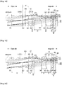
- FIGs. 1a and 1b are views illustrating the imaging lens according to the first embodiment.
- the imaging lens according to this embodiment includes first to third lens groups G1-G3, a filter 180 and a light receiving element 190, which are arranged sequentially from an object side to an image side so as to form the imaging lens in a camera module.
- the first lens group G1 may include a first lens 110
- the second lens group G2 may include a second lens 120 and a third lens 130
- the third lens group G3 may include fourth to seventh lenses 140-170.
- At least one of object surfaces and image surfaces of the above-described first lens 1102 to seventh lens 170 may be an aspherical surface, and when an aspherical surface is formed as at least one surface of the lenses, correction of various aberrations, such as spherical aberration, coma aberration and distortion, may be excellent.
- Table 1 shows EFLs, etc. of the imaging lens according to the first embodiment in a wide mode, a middle mode and a tele mode.
- a stop may be arranged between the first lens group G1 and the second lens group G2, and the position of the stop may be stationary, for example, the stop may be provided on the rear surface of the first lens group G1.
- the filter 180 may be a plate-shaped optical member, such as an infrared ray filter or the like
- the cover glass 190 may be a cover glass for protecting an optical member, for example, an imaging surface
- the light receiving element may be an image sensor stacked on a printed circuit board (not shown).
- the light emitting element may be the image sensor, and horizontal and/or vertical lengths of a unit pixel of the image sensor may be 2 ⁇ m (micrometer) or less.
- the above-described embodiment and other embodiments may provide imaging lenses which may be applied to a camera module having high pixels and/or a large number of pixels
- the above camera module may have an image sensor or light receiving element having high pixels and/or a large number of pixels, and in this case, horizontal and/or vertical lengths of a unit pixel thereof may be 2 ⁇ m or less.
- 'S11' may be an object surface of the first lens 110
- 'S12' may be an image surface of the first lens 120
- 'S21' may be an object surface of the second lens 120
- 'S22' may be an image surface of the second lens 120
- 'S31' may be an object surface of the second lens 130
- 'S32' may be an image surface of the third lens 130
- 'S41' may be an object surface of the fourth lens 140
- 'S42' may be an image surface of the fourth lens 140
- 'S51' may be an object surface of the fifth lens 150
- 'S52' may be an image surface of the fifth lens 150
- 'S61' may be an object surface of the sixth lens 160
- 'S62' may be an image surface of the sixth lens 160
- 'S71' may be an object surface of the seventh lens 170
- 'S72' may be an image surface of the seventh lens 170.
- Table 2 shows radiuses of curvature, etc. of the image surfaces and the object surfaces of the first lens 110 to the seventh lens 170 of the imaging lens according to the first embodiment.
- a radius of curvature of infinity indicates a flat surface
- a - sign indicates a surface which is convex towards the image side
- no sign i.e., a + value
- a to D are variable, and may have values given in Table 3 below.
- Table 3 A B C D Wide 2.493333109 3.033014803 0.652134553 0.037865415 Middle 2.303604572 2.311430255 1.560014501 0.031298517 Tele 0.108188844 0.1 6.117872231 -0.099701394
- Table 3 shows changes in the values of A to D of the image lens according to the first embodiment in the wide mode, the middle mode and the tele mode. That is, the value of A may be changed as the distance between the first lens group G1 and the second lens group G2 is changed, and the value of B may be changed as the distance between the second lens group G2 and the third lens group G3 is changed.
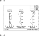
- FIG. 2a illustrates graphs showing aberrations of the imaging lens according to the first embodiment in the wide mode
- FIG. 2b illustrates graphs showing aberrations of the imaging lens according to the first embodiment in the middle mode
- FIG. 2c illustrates graphs showing aberrations of the imaging lens according to the first embodiment in the tele mode.
- FIGs. 3a and 3b are views illustrating an imaging lens according to a second embodiment. A detailed description of some parts in this embodiment, which are substantially the same as those in the above-described first embodiment, is omitted because it is considered to be unnecessary.
- the imaging lens according to this embodiment includes first to third lens groups G1-G3, a filter 180 and a light receiving element 190, which are arranged sequentially from an object side to an image side so as to form the imaging lens in a camera module.
- the first lens group G1 may include a first lens 110
- the second lens group G2 may include a second lens 120
- the third lens group G3 may include third to fifth lenses 130-150.
- Table 4 shows EFLs, etc. of the imaging lens according to the second embodiment in a wide mode, a middle mode and a tele mode.
- a stop may be arranged on the front surface, for example, an object surface, of the first lens group G1.
- Table 5 shows radiuses of curvature, etc. of the image surfaces and the object surfaces of the first lens 110 to the fifth lens 150 of the imaging lens according to the second embodiment.
- a to D are variable, and may have values given in Table 6 below.
- Table 6 A B C D Wide 1.628617519 2.7544747 0.589993963 0.1 Middle 1.594586616 2.1197223 1.259474236 0.089300774 Tele 0.1 0.1 4.983063739 -0.1
- Table 6 shows changes in the values of A to D of the image lens according to the second embodiment in the wide mode, the middle mode and the tele mode. That is, the value of A may be changed as the distance between the first lens group G1 and the second lens group G2 is changed, and the value of B may be changed as the distance between the second lens group G2 and the third lens group G3 is changed.
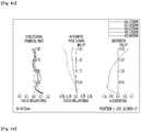
- FIG. 4a illustrates graphs showing aberrations of the imaging lens according to the second embodiment in the wide mode
- FIG. 4b illustrates graphs showing aberrations of the imaging lens according to the second embodiment in the middle mode
- FIG. 4c illustrates graphs showing aberrations of the imaging lens according to the second embodiment in the tele mode.
- FIGs. 5a and 5b are views illustrating an imaging lens according to a third embodiment. A detailed description of some parts in this embodiment, which are substantially the same as those in the above-described first and second embodiments, is omitted because it is considered to be unnecessary.
- the imaging lens according to this embodiment includes first to third lens groups G1-G3, a filter 180 and a light receiving element 190, which are arranged sequentially from an object side to an image side so as to form the imaging lens in a camera module.
- the first lens group G1 may include a first lens 110
- the second lens group G2 may include a second lens 120
- the third lens group G3 may include third to fifth lenses 130-150.
- the first lenses 110 in the first and second embodiments may be a prism, but the first lens 110 in this embodiment may not be a prism.
- Table 7 shows EFLs, etc. of the imaging lens according to the second embodiment in a wide mode and a tele mode.
- a stop may be arranged between the first lens group G1 and the second lens group G2.
- Table 7 shows radiuses of curvature, etc. of the image surfaces and the object surfaces of the first lens 110 to the fifth lens 150 of the imaging lens according to the third embodiment.
- [Table 8] Radius of curvature (mm) Thickness (mm) Refractive index Abbe's number S11 5.75201 3 1.661 20.4 S12 Infinity A S21 3.5461 1.498093 1.55442 56 S22 -4.885 B S31 -7.81358 3 1.661 20.4 S32 39.50551 0.137165 S41 -11.89454 0.567818 1.661 20.4 S42 -3.91053 0.068993 S51 -2.55616 0.770465 1.55442 56 S52 134.42418 0.1 S81 Infinity 0.21 S82 Infinity C+D S91 Infinity
- a to D are variable, and may have values given in Table 9 below.
- a B C D Wide 2.072867067 0.812389888 0.595820535 -0.005852723 Tele 0.1 0.100019525 3.332786668 -0.047616293
- Table 9 shows changes in the values of A to D of the image lens according to the second embodiment in the wide mode and the tele mode. That is, the value of A may be changed as the distance between the first lens group G1 and the second lens group G2 is changed, and the value of B may be changed as the distance between the second lens group G2 and the third lens group G3 is changed.
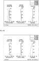
- FIG. 6a illustrates graphs showing aberrations of the imaging lens according to the third embodiment in the wide mode
- FIG. 6b illustrates graphs showing aberrations of the imaging lens according to the third embodiment in the tele mode.
- the camera module including the above-described imaging lens may be installed in various digital devices, such as a digital camera, a smart phone, a notebook, a tablet PC, etc., and particularly, be installed in a mobile device so as to implement a high-performance and ultra-thin zoom lens.
- An imaging lens according to embodiments is usable in a camera module and a digital device.
Landscapes
- Physics & Mathematics (AREA)
- General Physics & Mathematics (AREA)
- Optics & Photonics (AREA)
- Lenses (AREA)
- Engineering & Computer Science (AREA)
- Multimedia (AREA)
- Signal Processing (AREA)
Abstract
Description
- Embodiments relate to an imaging lens and a camera module and a digital device including the same.
- Conventional film cameras have been replaced by a camera module for mobile phones using a small-sized solid-state imaging element, such as a CCD or a CMOS, a digital still camera (DSC), a camcorder, a PC camera (an imaging device attached to a personal computer), etc., and these imaging devices are being developed with the goal of miniaturization and slimming.
- In order to satisfy this trend, miniaturization of light receiving elements, such as a charge coupled device (CCD), mounted in small-sized solid-state imaging devices is underway, and the part of an imaging device which occupies the largest volume is an imaging lens part.
- Therefore, the element of the imaging device, which is the key issue in terms of miniaturization and slimming, is an imaging lens which forms an image of an object.
- Here, the imaging lens requires not only a small size but also high performance in response to the high performance of the light receiving elements. However, a zoom lens, in which distances between lenses are variable, is widely used as the miniaturized imaging lens in order to implement high performance.
- The conventional imaging lens, particularly the zoom lens, may be excessively thick and thus not have a small size, and may be less sensitive at a high resolution and thus not implement high performance.
- Embodiments provide an imaging lens including a subminiature zoom lens having a small thickness.
- Embodiments provides an image lens, the sensitivity of which is not deteriorated even at a high resolution, so as to implement high performance.
- In one embodiment, an imaging lens includes first to third lens groups arranged sequentially from an object side to an image side and having refractive power, wherein distances to the second lens group and the third lens group from the first lens group are variable such that a tele mode having a narrow angle of view and a wide mode having a wide angle of view can be implemented, an EFL in a tele mode is no more than 2.5 times an EFL in a wide mode, 2<FNumber<5, and 15 mm<TTL≤40 mm.
- At least one second lens of the second lens group may have an object surface configured to be convex towards the object side and an image surface configured to be convex towards the image side.
- The first lens group may include one lens, the second lens group may include two lenses, and the third lens group may include four lenses.
- The first lens group may include one lens, the second lens group may include one lens, and the third lens group may include three lenses.
- The EFLs of the image lens may be within a range of 8.6 to 16.5.
- In another embodiment, a camera module includes the above-described imaging lens; a filter configured to selectively transmit light having passed through the imaging lens depending on a wavelength of the light; a light receiving element configured to receive light having passed through the filter, wherein a maximum distance between the first lens group and the light receiving element on an optical axis, as defined as a TTL, is more than 15 mm and is no more than 40 mm.
- A maximum aperture of lenses forming the first to third lens groups may be 0.2 to 0.3 times the TTL.
- The maximum aperture of the lenses may be 5 mm or less.
- An imaging lens having a zoom function according to one embodiment may be implemented as a subminiature zoom lens having a small thickness.
- Further, the sensitivity of the imaging lens is not deteriorated even at a high resolution, and thus the imaging lens may implement high performance.
-
-
FIGs. 1a and 1b are views illustrating an imaging lens according to a first embodiment, -
FIG. 2a illustrates graphs showing aberrations of the imaging lens according to the first embodiment in a wide mode,FIG. 2b illustrates graphs showing aberrations of the imaging lens according to the first embodiment in a middle mode, andFIG. 2c illustrates graphs showing aberrations of the imaging lens according to the first embodiment in a tele mode, -
FIGs. 3a and3b are views illustrating an imaging lens according to a second embodiment, -
FIG. 4a illustrates graphs showing aberrations of the imaging lens according to the second embodiment in a wide mode,FIG. 4b illustrates graphs showing aberrations of the imaging lens according to the second embodiment in a middle mode, andFIG. 4c illustrates graphs showing aberrations of the imaging lens according to the second embodiment in a tele mode, -
FIGs. 5a and5b are views illustrating an imaging lens according to a third embodiment, and -
FIG. 6a illustrates graphs showing aberrations of the imaging lens according to the third embodiment in a wide mode, andFIG. 6b illustrates graphs showing aberrations of the imaging lens according to the third embodiment in a tele mode. - Hereinafter, embodiments will be described with reference to the annexed drawings and description.
- In the following description of the embodiments, it will be understood that an 'object surface' means the surface of a lens facing an object side based on an optical axis, and an 'image surface' means the surface of the lens facing an image side based on the optical axis.
- Further, in the embodiments, it will be understood that "+ power" of a lens indicates a convergent lens which converges parallel light, and "- power" of a lens indicates a divergent lens which diverges parallel light.
- An imaging lens according to embodiments may include first to third lens groups arranged sequentially from an object side to an image side and having refractive power, and the first to third lens groups may be formed of plastic. The total magnification of the imaging lens is no more than 2.5 times, and particularly, a ratio of tele EFL/wide EFL may be no more than 2.5, and tele EFL and wide EFL may be equivalent focal lengths (EFLs) of the imaging lens in a tele mode and a wide mode. Further, in the imaging lens, 2<FNumber<5 and 15 mm<TTL≤40 mm may be satisfied. That is, the distances to the second lens group and the third lens group from the first lens group are variable such that a tele mode having a narrow angle of view and a wide mode having a wide angle of view can be implemented, and the EFL in the tele mode is no more than 2.5 times the EFL in the wide mode.
- Among the first to third lens groups, the first lens group may be formed of a prism, have a thickness of 3 mm or more, and be stationary. When the thickness of the first lens group is 3 mm or more, light is focused and may thus secure resolution. Further, second and third lens groups may move in the direction of an optical axis.
- Further, in order to reduce the total volume of the imaging lens, the maximum aperture of the first to third lens groups may be defined as T, and T may be 5 mm or less. In addition, a ratio of T to TTL (T/TTL) may be 0.2 to 0.3, for example, 0.25. Here, when T is excessively small, a quantity of light is decreased and the resolution of the imaging lens may be lowered, and when TTL is excessively lengthened, a quantity of necessary light is increased and the resolution of the imaging lens may be lowered.
- EFLs of imaging lenses according to first and second embodiments, which will be described below, may be 9.94 to 16.5, that is, tele EFLs may be 16.5 and wide EFLs may be 9.94.
- Further, EFLs of an imaging lens according to a third embodiment, which will be described below, may be 8.6 to 12.8, that is, a tele EFL may be 12.9 and a wide EFL may be 8.6.
-
FIGs. 1a and 1b are views illustrating the imaging lens according to the first embodiment. - The imaging lens according to this embodiment includes first to third lens groups G1-G3, a
filter 180 and alight receiving element 190, which are arranged sequentially from an object side to an image side so as to form the imaging lens in a camera module. - The first lens group G1 may include a
first lens 110, the second lens group G2 may include asecond lens 120 and athird lens 130, and the third lens group G3 may include fourth to seventh lenses 140-170. At least one of object surfaces and image surfaces of the above-described first lens 1102 to seventh lens 170 may be an aspherical surface, and when an aspherical surface is formed as at least one surface of the lenses, correction of various aberrations, such as spherical aberration, coma aberration and distortion, may be excellent. - Table 1 shows EFLs, etc. of the imaging lens according to the first embodiment in a wide mode, a middle mode and a tele mode.
[Table 1] Wide Middle Tele EFL 9.94 11 16.5 BFL 0.6521 1.56 6.1179 FFL -14.1764 -15.6106 -24.5528 FNumber 2.5193 2.7814 4.125 - A stop may be arranged between the first lens group G1 and the second lens group G2, and the position of the stop may be stationary, for example, the stop may be provided on the rear surface of the first lens group G1. The
filter 180 may be a plate-shaped optical member, such as an infrared ray filter or the like, thecover glass 190 may be a cover glass for protecting an optical member, for example, an imaging surface, and the light receiving element may be an image sensor stacked on a printed circuit board (not shown). The light emitting element may be the image sensor, and horizontal and/or vertical lengths of a unit pixel of the image sensor may be 2 µm (micrometer) or less. The above-described embodiment and other embodiments, which will be described below, may provide imaging lenses which may be applied to a camera module having high pixels and/or a large number of pixels, the above camera module may have an image sensor or light receiving element having high pixels and/or a large number of pixels, and in this case, horizontal and/or vertical lengths of a unit pixel thereof may be 2 µm or less. - 'S11' may be an object surface of the
first lens 110, 'S12' may be an image surface of thefirst lens 120, 'S21' may be an object surface of thesecond lens 120, 'S22' may be an image surface of thesecond lens 120, 'S31' may be an object surface of thesecond lens 130, 'S32' may be an image surface of thethird lens 130, 'S41' may be an object surface of thefourth lens 140, 'S42' may be an image surface of thefourth lens 140, 'S51' may be an object surface of thefifth lens 150, 'S52' may be an image surface of thefifth lens 150, 'S61' may be an object surface of the sixth lens 160, 'S62' may be an image surface of the sixth lens 160, 'S71' may be an object surface of the seventh lens 170, and 'S72' may be an image surface of the seventh lens 170. - Table 2 shows radiuses of curvature, etc. of the image surfaces and the object surfaces of the
first lens 110 to the seventh lens 170 of the imaging lens according to the first embodiment. Here, a radius of curvature of infinity indicates a flat surface, a - sign indicates a surface which is convex towards the image side, no sign, i.e., a + value, indicates a surface which is convex towards the object side, and these are the same in other embodiments which will be described below.[Table 2] Radius of curvature (mm) Thickness (mm) Refractive index Abbe's number S11 -83.50746 4.75 1.55442 56 S12 Infinity A S21 15.22416 1.598591 1.55442 56 S22 -5.33888 0.100157 S31 -8.05492 0.65751 1.661 20.4 S32 -11.57797 0.100277+B S41 6.92015 1.999811 1.55442 56 S42 51.68015 0.192691 S51 -7.22958 2 1.661 20.4 S52 -60.27491 0.829393 S61 -3.85356 0.3 1.55442 56 S62 4.76038 0.101489 S71 2.66895 0.639961 1.661 20.4 S72 5.07207 0.15318 S81 Infinity 0.21 S82 Infinity C+D S91 Infinity - Here, A to D are variable, and may have values given in Table 3 below.
[Table 3] A B C D Wide 2.493333109 3.033014803 0.652134553 0.037865415 Middle 2.303604572 2.311430255 1.560014501 0.031298517 Tele 0.108188844 0.1 6.117872231 -0.099701394 - Table 3 shows changes in the values of A to D of the image lens according to the first embodiment in the wide mode, the middle mode and the tele mode. That is, the value of A may be changed as the distance between the first lens group G1 and the second lens group G2 is changed, and the value of B may be changed as the distance between the second lens group G2 and the third lens group G3 is changed.
FIG. 2a illustrates graphs showing aberrations of the imaging lens according to the first embodiment in the wide mode,FIG. 2b illustrates graphs showing aberrations of the imaging lens according to the first embodiment in the middle mode, andFIG. 2c illustrates graphs showing aberrations of the imaging lens according to the first embodiment in the tele mode. In the respective figures, graphs showing longitudinal spherical aberration, astigmatic field curves, and distortion are illustrated sequentially from the left, the Y-axis means the sizes of images, the X-axis means focal distances (in mm) and degrees of distortion (in %), and as curves approach the Y-axis, an aberration correcting function may be improved. -
FIGs. 3a and3b are views illustrating an imaging lens according to a second embodiment. A detailed description of some parts in this embodiment, which are substantially the same as those in the above-described first embodiment, is omitted because it is considered to be unnecessary. - The imaging lens according to this embodiment includes first to third lens groups G1-G3, a
filter 180 and alight receiving element 190, which are arranged sequentially from an object side to an image side so as to form the imaging lens in a camera module. - The first lens group G1 may include a
first lens 110, the second lens group G2 may include asecond lens 120, and the third lens group G3 may include third to fifth lenses 130-150. - Table 4 shows EFLs, etc. of the imaging lens according to the second embodiment in a wide mode, a middle mode and a tele mode.
[Table 4] Wide Middle Tele EFL 9.94 11 16.5 BFL 0.59 1.2595 4.9831 FFL -21.0035 -22.7093 -31.9802 FNumber 2.485 2.75 4.125 - A stop may be arranged on the front surface, for example, an object surface, of the first lens group G1. Table 5 shows radiuses of curvature, etc. of the image surfaces and the object surfaces of the
first lens 110 to thefifth lens 150 of the imaging lens according to the second embodiment.[Table 5] Radius of curvature (mm) Thickness (mm) Refractive index Abbe's number S11 29.49037 4.75 1.5653 33.93 S12 Infinity A S21 20.21818 1.662728 1.491 51 S22 -7.51016 0.1+B S31 3.91412 1.253145 1.491 51 S32 -110.26845 0.170351 S41 -5.40555 1.999667 1.661 20.4 S42 -336.87025 1.280838 S51 -2.31164 0.3 1.49939 47.92 S52 135.93422 0.1 S81 Infinity 0.21 S82 Infinity C+D S91 Infinity - Here, A to D are variable, and may have values given in Table 6 below.
[Table 6] A B C D Wide 1.628617519 2.7544747 0.589993963 0.1 Middle 1.594586616 2.1197223 1.259474236 0.089300774 Tele 0.1 0.1 4.983063739 -0.1 - Table 6 shows changes in the values of A to D of the image lens according to the second embodiment in the wide mode, the middle mode and the tele mode. That is, the value of A may be changed as the distance between the first lens group G1 and the second lens group G2 is changed, and the value of B may be changed as the distance between the second lens group G2 and the third lens group G3 is changed.
FIG. 4a illustrates graphs showing aberrations of the imaging lens according to the second embodiment in the wide mode,FIG. 4b illustrates graphs showing aberrations of the imaging lens according to the second embodiment in the middle mode, andFIG. 4c illustrates graphs showing aberrations of the imaging lens according to the second embodiment in the tele mode. -
FIGs. 5a and5b are views illustrating an imaging lens according to a third embodiment. A detailed description of some parts in this embodiment, which are substantially the same as those in the above-described first and second embodiments, is omitted because it is considered to be unnecessary. - The imaging lens according to this embodiment includes first to third lens groups G1-G3, a
filter 180 and alight receiving element 190, which are arranged sequentially from an object side to an image side so as to form the imaging lens in a camera module. - The first lens group G1 may include a
first lens 110, the second lens group G2 may include asecond lens 120, and the third lens group G3 may include third to fifth lenses 130-150. Further, thefirst lenses 110 in the first and second embodiments may be a prism, but thefirst lens 110 in this embodiment may not be a prism. - Table 7 shows EFLs, etc. of the imaging lens according to the second embodiment in a wide mode and a tele mode.
[Table 7] Wide Tele EFL 8.6 12.8 BFL 0.5958 3.3328 FFL -11.0385 -20.9963 FNumber 2.15 3.2 - A stop may be arranged between the first lens group G1 and the second lens group G2. Table 7 shows radiuses of curvature, etc. of the image surfaces and the object surfaces of the
first lens 110 to thefifth lens 150 of the imaging lens according to the third embodiment.[Table 8] Radius of curvature (mm) Thickness (mm) Refractive index Abbe's number S11 5.75201 3 1.661 20.4 S12 Infinity A S21 3.5461 1.498093 1.55442 56 S22 -4.885 B S31 -7.81358 3 1.661 20.4 S32 39.50551 0.137165 S41 -11.89454 0.567818 1.661 20.4 S42 -3.91053 0.068993 S51 -2.55616 0.770465 1.55442 56 S52 134.42418 0.1 S81 Infinity 0.21 S82 Infinity C+D S91 Infinity - Here, A to D are variable, and may have values given in Table 9 below.
[Table 9] A B C D Wide 2.072867067 0.812389888 0.595820535 -0.005852723 Tele 0.1 0.100019525 3.332786668 -0.047616293 - Table 9 shows changes in the values of A to D of the image lens according to the second embodiment in the wide mode and the tele mode. That is, the value of A may be changed as the distance between the first lens group G1 and the second lens group G2 is changed, and the value of B may be changed as the distance between the second lens group G2 and the third lens group G3 is changed.
FIG. 6a illustrates graphs showing aberrations of the imaging lens according to the third embodiment in the wide mode, andFIG. 6b illustrates graphs showing aberrations of the imaging lens according to the third embodiment in the tele mode. - The camera module including the above-described imaging lens may be installed in various digital devices, such as a digital camera, a smart phone, a notebook, a tablet PC, etc., and particularly, be installed in a mobile device so as to implement a high-performance and ultra-thin zoom lens.
- Although embodiments have been described with reference to a number of illustrative embodiments thereof, it should be understood that numerous other modifications and embodiments can be devised by those skilled in the art that will fall within the spirit and scope of the principles of the disclosure. For example, various variations and modifications are possible in the component parts and/or arrangements of the subject combination arrangement within the scope of the disclosure, the drawings and the appended claims. Further, it should be understood that differences regarding the modifications and applications are within the spirit and scope of the disclosure which is defined in the appended claims and their equivalents.
- Modes for carrying out the disclosure have been described in the best mode for carrying out the disclosure.
- An imaging lens according to embodiments is usable in a camera module and a digital device.
Claims (10)
- An imaging lens comprising first to third lens groups arranged sequentially from an object side to an image side and having refractive power, wherein:distances to the second lens group and the third lens group from the first lens group are variable such that a tele mode having a narrow angle of view and a wide mode having a wide angle of view can be implemented; andan EFL in a tele mode is no more than 2.5 times an EFL in a wide mode, 2<FNumber<5, and 15 mm<TTL≤40 mm.
- The imaging lens according to claim 1, wherein a second lens of the second lens group has an object surface configured to be convex towards the object side and an image surface configured to be convex towards the image side.
- The imaging lens according to claim 1, wherein the first lens group comprises one lens, the second lens group comprises two lenses, and the third lens group comprises four lenses.
- The imaging lens according to claim 1, wherein the first lens group comprises one lens, the second lens group comprises one lens, and the third lens group comprises three lenses.
- The imaging lens according to claim 1, wherein the EFLs of the image lens are within a range of 8.6 to 16.5.
- The imaging lens according to claim 1, wherein a total magnification of the imaging lens is no more than 2.5 times.
- The imaging lens according to claim 1, wherein the first lens group comprises a prism, and has a thickness of 3 mm or more.
- A camera module comprising:the imaging lens according to any one of claims 1 to 7;a filter configured to selectively transmit light having passed through the imaging lens depending on a wavelength of the light; anda light receiving element configured to receive light having passed through the filter,wherein a maximum distance between the first lens group and the light receiving element on an optical axis, as defined as a TTL, is more than 15 mm and is no more than 40 mm.
- The camera module according to claim 8, wherein a maximum aperture of lenses forming the first to third lens groups is 0.2 to 0.3 times the TTL.
- The camera module according to claim 9, wherein the maximum aperture of the lenses is 5 mm or less.
Applications Claiming Priority (2)
| Application Number | Priority Date | Filing Date | Title |
|---|---|---|---|
| KR1020180007114A KR102619639B1 (en) | 2018-01-19 | 2018-01-19 | Image pickup lens and camera module including the same |
| PCT/KR2019/000741 WO2019143166A1 (en) | 2018-01-19 | 2019-01-18 | Imaging lens and camera module comprising same |
Publications (3)
| Publication Number | Publication Date |
|---|---|
| EP3742214A1 true EP3742214A1 (en) | 2020-11-25 |
| EP3742214A4 EP3742214A4 (en) | 2021-12-08 |
| EP3742214B1 EP3742214B1 (en) | 2026-01-14 |
Family
ID=67301899
Family Applications (1)
| Application Number | Title | Priority Date | Filing Date |
|---|---|---|---|
| EP19741742.1A Active EP3742214B1 (en) | 2018-01-19 | 2019-01-18 | Imaging lens and camera module comprising the same |
Country Status (5)
| Country | Link |
|---|---|
| US (1) | US11143844B2 (en) |
| EP (1) | EP3742214B1 (en) |
| KR (1) | KR102619639B1 (en) |
| CN (1) | CN111630428B (en) |
| WO (1) | WO2019143166A1 (en) |
Families Citing this family (2)
| Publication number | Priority date | Publication date | Assignee | Title |
|---|---|---|---|---|
| TWI730637B (en) * | 2020-02-24 | 2021-06-11 | 大陽科技股份有限公司 | Camera module and electronic device |
| CN112241064B (en) * | 2020-08-31 | 2025-03-11 | 浙江舜宇光学有限公司 | Optical imaging lens assembly |
Family Cites Families (17)
| Publication number | Priority date | Publication date | Assignee | Title |
|---|---|---|---|---|
| KR100467953B1 (en) | 2002-04-02 | 2005-01-24 | 삼성테크윈 주식회사 | Zoom lens |
| JP4508525B2 (en) * | 2002-12-25 | 2010-07-21 | オリンパス株式会社 | Optical path bending zoom optical system |
| JP2004348082A (en) * | 2003-05-26 | 2004-12-09 | Olympus Corp | Optical path bending optical system |
| KR100604315B1 (en) * | 2004-01-20 | 2006-07-25 | 삼성테크윈 주식회사 | Zoom lens |
| JP2005274662A (en) | 2004-03-23 | 2005-10-06 | Fujinon Corp | Zoom lens having cemented lens |
| JP4845458B2 (en) * | 2005-09-08 | 2011-12-28 | キヤノン株式会社 | Zoom lens and imaging apparatus having the same |
| JP4681842B2 (en) * | 2004-09-30 | 2011-05-11 | キヤノン株式会社 | Zoom lens and imaging apparatus having the same |
| US7248418B2 (en) * | 2004-09-30 | 2007-07-24 | Canon Kabushiki Kaisha | Zoom lens system and image pickup apparatus including the same |
| JP4813136B2 (en) * | 2005-09-21 | 2011-11-09 | オリンパスイメージング株式会社 | Zoom optical system and image pickup apparatus having the same |
| KR100771795B1 (en) | 2006-04-20 | 2007-10-30 | 삼성전기주식회사 | Zooming Optical System Having a Liquid Lens |
| KR20090046060A (en) * | 2007-11-05 | 2009-05-11 | 엘지이노텍 주식회사 | Zoom lens |
| JPWO2010001545A1 (en) * | 2008-07-02 | 2011-12-15 | パナソニック株式会社 | Zoom lens system, imaging device and camera |
| KR20100056268A (en) * | 2008-11-19 | 2010-05-27 | 삼성전자주식회사 | Zoom lens |
| JP2013044964A (en) * | 2011-08-24 | 2013-03-04 | Tamron Co Ltd | Zoom lens |
| WO2013161995A1 (en) * | 2012-04-27 | 2013-10-31 | コニカミノルタ株式会社 | Zoom lens, image-capturing device, and digital instrument |
| JP6172947B2 (en) * | 2013-01-11 | 2017-08-02 | キヤノン株式会社 | Zoom lens and imaging apparatus having the same |
| KR102422781B1 (en) * | 2015-03-11 | 2022-07-19 | 엘지이노텍 주식회사 | Image pickup lens, camera module and digital device including the same |
-
2018
- 2018-01-19 KR KR1020180007114A patent/KR102619639B1/en active Active
-
2019
- 2019-01-18 US US16/957,953 patent/US11143844B2/en active Active
- 2019-01-18 EP EP19741742.1A patent/EP3742214B1/en active Active
- 2019-01-18 WO PCT/KR2019/000741 patent/WO2019143166A1/en not_active Ceased
- 2019-01-18 CN CN201980008344.8A patent/CN111630428B/en active Active
Also Published As
| Publication number | Publication date |
|---|---|
| CN111630428B (en) | 2023-12-01 |
| EP3742214B1 (en) | 2026-01-14 |
| US11143844B2 (en) | 2021-10-12 |
| KR102619639B1 (en) | 2023-12-29 |
| CN111630428A (en) | 2020-09-04 |
| KR20190088700A (en) | 2019-07-29 |
| EP3742214A4 (en) | 2021-12-08 |
| WO2019143166A1 (en) | 2019-07-25 |
| US20200326508A1 (en) | 2020-10-15 |
Similar Documents
| Publication | Publication Date | Title |
|---|---|---|
| US11796773B2 (en) | Subminiature optical system and portable device including the same | |
| US9279958B2 (en) | Imaging lens and imaging apparatus equipped with the imaging lens | |
| US7561347B2 (en) | Subminiature optical system | |
| US6961191B2 (en) | Single focus lens | |
| KR101802036B1 (en) | Lens system and optical comprising the same | |
| US7072123B2 (en) | Imaging lens including three lens components | |
| KR102903618B1 (en) | Image pickup lens, camera module and digital device including the same | |
| JP2009069195A (en) | Imaging lens, camera module and imaging equipment | |
| US10656410B2 (en) | Imaging lens, camera module and digital device comprising same | |
| US7099092B2 (en) | Single focus wide-angle lens | |
| KR20140056494A (en) | Optical system | |
| KR102422781B1 (en) | Image pickup lens, camera module and digital device including the same | |
| KR102427796B1 (en) | Image pickup lens, camera module and digital device including the same | |
| EP3742214B1 (en) | Imaging lens and camera module comprising the same | |
| KR20180071015A (en) | Image pickup lens, camera module and digital device including the same | |
| KR101221703B1 (en) | Image pick-up lens, image pick-up unit and portable terminal | |
| US20080024880A1 (en) | Compact image pickup lens | |
| KR101872857B1 (en) | Subminiature wide angle image pickup lens system | |
| CN108431663B (en) | Standard to telephoto lens system for photographing images | |
| US6882483B1 (en) | Optical system with particular optical distortion | |
| KR20220032891A (en) | Optical system | |
| KR102599618B1 (en) | Image pickup lens, camera module and digital device including the same | |
| KR102528499B1 (en) | Image pickup lens, camera module and digital device including the same | |
| KR102493388B1 (en) | Image pickup lens, camera module and digital device including the same | |
| CN116560039B (en) | Imaging lens group and camera module |
Legal Events
| Date | Code | Title | Description |
|---|---|---|---|
| STAA | Information on the status of an ep patent application or granted ep patent |
Free format text: STATUS: THE INTERNATIONAL PUBLICATION HAS BEEN MADE |
|
| PUAI | Public reference made under article 153(3) epc to a published international application that has entered the european phase |
Free format text: ORIGINAL CODE: 0009012 |
|
| STAA | Information on the status of an ep patent application or granted ep patent |
Free format text: STATUS: REQUEST FOR EXAMINATION WAS MADE |
|
| 17P | Request for examination filed |
Effective date: 20200623 |
|
| AK | Designated contracting states |
Kind code of ref document: A1 Designated state(s): AL AT BE BG CH CY CZ DE DK EE ES FI FR GB GR HR HU IE IS IT LI LT LU LV MC MK MT NL NO PL PT RO RS SE SI SK SM TR |
|
| AX | Request for extension of the european patent |
Extension state: BA ME |
|
| DAV | Request for validation of the european patent (deleted) | ||
| DAX | Request for extension of the european patent (deleted) | ||
| A4 | Supplementary search report drawn up and despatched |
Effective date: 20211105 |
|
| RIC1 | Information provided on ipc code assigned before grant |
Ipc: G02B 15/14 20060101ALI20211029BHEP Ipc: G03B 17/12 20210101ALI20211029BHEP Ipc: H04N 5/225 20060101ALI20211029BHEP Ipc: G02B 13/00 20060101AFI20211029BHEP |
|
| STAA | Information on the status of an ep patent application or granted ep patent |
Free format text: STATUS: EXAMINATION IS IN PROGRESS |
|
| 17Q | First examination report despatched |
Effective date: 20230804 |
|
| GRAP | Despatch of communication of intention to grant a patent |
Free format text: ORIGINAL CODE: EPIDOSNIGR1 |
|
| STAA | Information on the status of an ep patent application or granted ep patent |
Free format text: STATUS: GRANT OF PATENT IS INTENDED |
|
| RIC1 | Information provided on ipc code assigned before grant |
Ipc: G02B 13/00 20060101AFI20250711BHEP Ipc: G03B 17/12 20060101ALI20250711BHEP Ipc: G02B 15/14 20060101ALI20250711BHEP |
|
| INTG | Intention to grant announced |
Effective date: 20250725 |
|
| GRAS | Grant fee paid |
Free format text: ORIGINAL CODE: EPIDOSNIGR3 |
|
| GRAA | (expected) grant |
Free format text: ORIGINAL CODE: 0009210 |
|
| STAA | Information on the status of an ep patent application or granted ep patent |
Free format text: STATUS: THE PATENT HAS BEEN GRANTED |
|
| AK | Designated contracting states |
Kind code of ref document: B1 Designated state(s): AL AT BE BG CH CY CZ DE DK EE ES FI FR GB GR HR HU IE IS IT LI LT LU LV MC MK MT NL NO PL PT RO RS SE SI SK SM TR |
|
| REG | Reference to a national code |
Ref country code: CH Ref legal event code: F10 Free format text: ST27 STATUS EVENT CODE: U-0-0-F10-F00 (AS PROVIDED BY THE NATIONAL OFFICE) Effective date: 20260114 Ref country code: GB Ref legal event code: FG4D |
|
| REG | Reference to a national code |
Ref country code: DE Ref legal event code: R096 Ref document number: 602019080341 Country of ref document: DE |
|
| REG | Reference to a national code |
Ref country code: NL Ref legal event code: FP Ref country code: IE Ref legal event code: FG4D |
|
| PGFP | Annual fee paid to national office [announced via postgrant information from national office to epo] |
Ref country code: GB Payment date: 20260309 Year of fee payment: 8 |
|
| PGFP | Annual fee paid to national office [announced via postgrant information from national office to epo] |
Ref country code: DE Payment date: 20260305 Year of fee payment: 8 |
|
| PGFP | Annual fee paid to national office [announced via postgrant information from national office to epo] |
Ref country code: NL Payment date: 20260305 Year of fee payment: 8 |
|
| PGFP | Annual fee paid to national office [announced via postgrant information from national office to epo] |
Ref country code: FR Payment date: 20260309 Year of fee payment: 8 |