EP3742132A1 - Radiometrisches füllstandmessgerät mit referenzszintillator - Google Patents
Radiometrisches füllstandmessgerät mit referenzszintillator Download PDFInfo
- Publication number
- EP3742132A1 EP3742132A1 EP19176563.5A EP19176563A EP3742132A1 EP 3742132 A1 EP3742132 A1 EP 3742132A1 EP 19176563 A EP19176563 A EP 19176563A EP 3742132 A1 EP3742132 A1 EP 3742132A1
- Authority
- EP
- European Patent Office
- Prior art keywords
- scintillator
- light signal
- photodetector
- measurement
- measuring device
- Prior art date
- Legal status (The legal status is an assumption and is not a legal conclusion. Google has not performed a legal analysis and makes no representation as to the accuracy of the status listed.)
- Granted
Links
Images


Classifications
-
- G—PHYSICS
- G01—MEASURING; TESTING
- G01T—MEASUREMENT OF NUCLEAR OR X-RADIATION
- G01T1/00—Measuring X-radiation, gamma radiation, corpuscular radiation, or cosmic radiation
- G01T1/16—Measuring radiation intensity
- G01T1/20—Measuring radiation intensity with scintillation detectors
- G01T1/204—Measuring radiation intensity with scintillation detectors the detector being a liquid
-
- G—PHYSICS
- G01—MEASURING; TESTING
- G01F—MEASURING VOLUME, VOLUME FLOW, MASS FLOW OR LIQUID LEVEL; METERING BY VOLUME
- G01F23/00—Indicating or measuring liquid level or level of fluent solid material, e.g. indicating in terms of volume or indicating by means of an alarm
- G01F23/22—Indicating or measuring liquid level or level of fluent solid material, e.g. indicating in terms of volume or indicating by means of an alarm by measuring physical variables, other than linear dimensions, pressure or weight, dependent on the level to be measured, e.g. by difference of heat transfer of steam or water
- G01F23/28—Indicating or measuring liquid level or level of fluent solid material, e.g. indicating in terms of volume or indicating by means of an alarm by measuring physical variables, other than linear dimensions, pressure or weight, dependent on the level to be measured, e.g. by difference of heat transfer of steam or water by measuring the variations of parameters of electromagnetic or acoustic waves applied directly to the liquid or fluent solid material
- G01F23/284—Electromagnetic waves
- G01F23/288—X-rays; Gamma rays or other forms of ionising radiation
-
- G—PHYSICS
- G01—MEASURING; TESTING
- G01F—MEASURING VOLUME, VOLUME FLOW, MASS FLOW OR LIQUID LEVEL; METERING BY VOLUME
- G01F1/00—Measuring the volume flow or mass flow of fluid or fluent solid material wherein the fluid passes through a meter in a continuous flow
- G01F1/76—Devices for measuring mass flow of a fluid or a fluent solid material
- G01F1/78—Direct mass flowmeters
-
- G—PHYSICS
- G01—MEASURING; TESTING
- G01F—MEASURING VOLUME, VOLUME FLOW, MASS FLOW OR LIQUID LEVEL; METERING BY VOLUME
- G01F25/00—Testing or calibration of apparatus for measuring volume, volume flow or liquid level or for metering by volume
- G01F25/20—Testing or calibration of apparatus for measuring volume, volume flow or liquid level or for metering by volume of apparatus for measuring liquid level
-
- G—PHYSICS
- G01—MEASURING; TESTING
- G01N—INVESTIGATING OR ANALYSING MATERIALS BY DETERMINING THEIR CHEMICAL OR PHYSICAL PROPERTIES
- G01N9/00—Investigating density or specific gravity of materials; Analysing materials by determining density or specific gravity
- G01N9/24—Investigating density or specific gravity of materials; Analysing materials by determining density or specific gravity by observing the transmission of wave or particle radiation through the material
-
- G—PHYSICS
- G01—MEASURING; TESTING
- G01T—MEASUREMENT OF NUCLEAR OR X-RADIATION
- G01T1/00—Measuring X-radiation, gamma radiation, corpuscular radiation, or cosmic radiation
- G01T1/16—Measuring radiation intensity
- G01T1/167—Measuring radioactive content of objects, e.g. contamination
Definitions
- the invention relates to a radiometric level measuring device for level measurement, for density measurement and / or for mass flow measurement.
- the invention relates to a method for compensating for a measurement deviation of a scintillator and / or a photodetector that is used in the radiometric level measuring device.
- the invention also relates to a use, a program element and a computer-readable medium.
- a radiometric level measuring device can for example be used to measure a certain level of a filling material, e.g. in a container, i.e. to indicate whether a predefined upper, lower or other limit of the fill level in the container has been reached.
- the container can be a vessel or measuring tank of any shape.
- the container can also be a channel, for example a stream or river bed.
- the radiometric level measuring device can, for example, use a gamma emitter for transmitting a radiometric signal and / or gamma radiation; this can be received by a detector for measurement purposes.
- the detector can contain a scintillator that sends a light signal when it is hit by a gamma ray, for example.
- the amplitude and / or the frequency of the light signal can be dependent on, for example, the temperature of the scintillator, and thereby increase Lead to measurement deviations compared to a reference measurement. Such measurement deviations can influence the measurement accuracy.
- a radiometric filling level measuring device is used, for example, for filling level measurement and / or further measurements of a filling material, for example for measuring a level, a density and / or a flow of the filling material.
- the radiometric level measuring device has the first scintillator and the photodetector.
- the scintillator sends in Light signal if it is hit by radioactive radiation, for example.
- the first scintillator is the primary scintillator, the measurement results of which are used by the radiometric level measuring device.
- the photodetector can, for example, be a photomultiplier, photoelectron multiplier (photomultiplier tube, PMT), a so-called microchannel plate (micro channel plate photomultiplier, MCP-PMT, MCP), a silicon photomultiplier (e.g. a so-called avalanche photodiode), a photodiode array and / or another detector.
- the first scintillator and / or the photodetector can have a measurement deviation that is caused, for example, by temperature differences and / or by aging of at least one of these components.
- a second scintillator detects radioactive radiation that originates from its own radioactive components.
- the first scintillator in response to radioactive radiation, sends a first light signal and the second scintillator sends a second light signal.
- the first light signal is different from the second light signal, e.g. regarding amplitude, color and / or other characteristics.
- the photodetector receives the first light signal from the first scintillator and the second light signal from the second scintillator.
- the photodetector converts the light signals into electrical signals or electrical pulses.
- For evaluating the electrical pulses generated by the photodetector e.g. Amplifier with a downstream discriminator and / or an amplifier with downstream pulse amplitude measurement can be used.
- a comparator compares the electrical signals with stored reference signals.
- the comparator can be implemented as hardware and / or as software.
- the hardware component can be implemented, for example, as special hardware and / or, for example, as part of a chip that also contains a processor.
- the temperature curves of the first and second scintillators and / or the difference between the two temperature curves are stored in the level measuring device, for example in a memory, in particular in a non-volatile memory, within the device and / or in a memory or a database to which the device has access.
- the temperature curves can be present and / or stored as a function of temperature, for example, as measured values and / or as deviations from measured values compared to a “standard measured value” (eg 20 ° C.).
- the first and second scintillators can be made of different materials; these different materials can have different temperature profiles.
- the temperature curves can be measured, for example, during the manufacture of the level measuring device.
- the temperature curves can also - additionally or alternatively - be measured during the operation of the level measuring device. Temperature curves measured in this way can be used, for example, to create a time series by means of which, for example, aging of components of the fill level measuring device can be analyzed.
- an amplification of the photodetector and / or of a subsystem that has the first scintillator and the photodetector is adapted in response to the comparison of the electrical signals and the stored reference signals.
- the adaptation can e.g. happen by changing a voltage of a high voltage supply, which acts on the photodetector.
- the adaptation can e.g. take place by means of a change in a gain of an amplifier connected downstream of the photodetector.
- the comparison and / or the adaptation can for example by means of a processor or controller and / or by means of special hardware, e.g. using a DSP (Digital Signal Processor), an analog computer and / or an artificial neural network (ANN).
- DSP Digital Signal Processor
- ANN artificial neural network
- This method advantageously at least partially compensates for measurement deviations of the first scintillator and / or of the photodetector.
- this method has a high degree of stability against aging.
- the method has a further step of determining the current temperature and the reference signal stored in a manner that matches the temperature. This relationship is sometimes referred to as the "temperature response".
- the current temperature can, for example, be measured directly on the measuring devices; it can be measured indirectly, e.g. by means of a remote thermometer, and / or indirectly by inferring the outside temperature of the measuring devices to the current temperature of the measuring devices. The accuracy of the measurements and / or the compensation can thus be further improved.
- the measurement deviation is a function of the temperature
- the reference signals stored for the temperature are stored in a comparison table.
- the reference signal can e.g. be stored and / or available as an array of reference signals which assigns a reference signal to a specific temperature. This can contribute to quick and / or structured access to the measured values of the reference signals.
- the first scintillator is adjacent to the second scintillator.
- the neighborhood can e.g. can be realized by mechanical and / or thermal coupling.
- the reception of the light signals by means of the photodetector can, for example, be improved by the proximity.
- a very similar temperature of the two scintillators can be achieved.
- the measurement deviation of the first scintillator and / or the photodetector is caused by aging of the first scintillator and / or the photodetector.
- the method can thereby also take into account these - and / or other - effects that can cause a measurement deviation.
- a differentiation is made between the first light signal from the first scintillator and the second light signal from the second scintillator on the basis of a different transit time, a different color and / or a different intensity of the light signals.
- the differentiation can be carried out by means of a differentiating device.
- the discriminator can, for example, be simplified and / or offer improved precision.
- the second scintillator is one of the following scintillators: Lutetium Aluminum Garnet, LuAG, Cerium-doped Lutetium Yttrium Silicate, LYSO, Lutetium Oxyorthosilicate, LSO, Yttrium Aluminum Perovskite (Cerium), YAP, Yttrium Aluminum Garnet, YAG, and / or a similar scintillator.
- These types of scintillators not only detect light signals, but are also transmitters of radioactive radiation due to their own radioactivity. In addition, at least some of these scintillators show little or very little aging.
- the second scintillator By using the second scintillator, light signals or pulses are always detected in a normal operating state of the radiometric fill level measuring device. If these pulses are no longer detected, there may be a fault in the measuring chain, for example a defect in the amplifier, the photodetector and / or other components of the level measuring device. In this case an alarm is sent, based on which predefined actions can be carried out; e.g. maintenance can be initiated.
- the second scintillator is shielded from the gamma emitter and / or a further external radiation source. This results in a clear separation of the first and second scintillator, so that the first scintillator only receives radioactive radiation from the gamma emitter and / or a further external radiation source, but the second scintillator only receives radioactive radiation from the second scintillator itself clearer, methodical separation of the first scintillator (eg for measurement) from the second reference scintillator (eg as a reference).
- the radiometric fill level measuring device furthermore has a distinguishing device which is set up to differentiate the first light signal and the second light signal on the basis of a different signal transit time, a different color and / or intensity of the first light signal and the second light signal.
- a distinguishing device which is set up to differentiate the first light signal and the second light signal on the basis of a different signal transit time, a different color and / or intensity of the first light signal and the second light signal.
- These different signal propagation times can be distinguished, for example, in that a photodetector is arranged at a first end (e.g. "bottom") of the first scintillator and a further photodetector is arranged at a second end (e.g. "top") of the first scintillator and on the second scintillator.
- the signals from the second scintillator can be separated by the different signal propagation times in relation to the two photodetectors.
- the second scintillator is one of the following scintillators: Lutetium Aluminum Garnet, LuAG, Cerium-doped Lutetium Yttrium Silicate, LYSO, Lutetium Oxyorthosilicate, LSO, Yttrium Aluminum Perovskite (Cerium), YAP, Yttrium Aluminum Garnet, YAG, and / or a similar scintillator.
- Another aspect of the invention relates to a use of a level measuring device as described above and / or below for radiometric level measurement, limit level measurement, flow measurement, mass flow measurement and / or density measurement.
- Another aspect of the invention relates to a program element which, when it is executed on a processor or a processor unit of a measuring device, instructs the measuring device to carry out the method described above and / or below.
- Another aspect of the invention relates to a computer-readable medium on which said program element is stored.
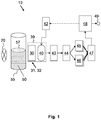
- Fig. 1 shows a schematic sketch of a radiometric fill level measuring device 10.
- the functional components of the fill level measuring device 10 are shown as logical blocks. At least some of these logical blocks can be implemented as hardware, as software or also partly as hardware and partly as software. The logical blocks can be physically separate or located on the same component.
- the comparator 47 can be implemented as independent hardware, as part of a chip and / or as software that runs on the processor unit 48.
- the radiometric filling level measuring device 10 has a scintillator arrangement 30 which is set up to detect radioactive radiation from a gamma emitter 20.
- a container 55 is arranged between the gamma emitter 20 and the scintillator arrangement 30 and contains a filling material 50 with a filling level 57.
- the scintillator arrangement 30 can have a first scintillator 31 and a second scintillator 32.
- the scintillators 31 and 32 emit light signals in response to radioactive radiation.
- the scintillator arrangement 30 are combined in this drawing together with a photodetector 40 to form a subsystem 39 (dashed), which is shown below (in Figures 2a to 2e ) is shown in different embodiments.
- the light signals from the first and second scintillators are received by the photodetector 40 and converted into electrical signals.
- the photodetector 40 can be, for example, a photomultiplier or a photoelectron multiplier (photomultiplier tube, PMT). Such a photomultiplier has a high-voltage supply 42, which can be activated, for example, by a computing and control unit or processor unit 48.
- an amplifier 43 is arranged, which amplifies the electrical signals from the photodetector 40.
- a discriminator or differentiating device 44 is then arranged, which divides the electrical signals from the amplifier 43 into signals 45, 46 which were caused by radioactive radiation and were detected by the first scintillator 31 and the second scintillator 32, respectively. The division can take place, for example, on the basis of a different signal transit time, a different color and / or intensity of the first or the second light signal.
- a downstream comparator 47 is set up to compare the electrical signals - for example the electrical signals which originate from the second light signal - with stored electrical reference signals.
- the comparator 47 can be implemented as hardware and / or as software.
- the hardware component can be implemented, for example, as special hardware and / or, for example, as part of a chip which also contains a processor or can also be located in the processor 48.
- the electrical reference signals can, for example, comply with temperature curves.
- the temperature curves can be measured, for example, during the manufacture of the filling level measuring device 10.
- the temperature profiles can additionally or alternatively also be measured during the operation of the fill level measuring device 10.
- the measurement data can be further processed in the processor unit or computing and control unit 48; a format adaptation and / or further calculations can be carried out, for example.
- the measurement data are available at an output 49 to disposal.
- the measurement data can be available in a format that is suitable for communication via WLAN (wireless LAN) and / or for a protocol such as LTE, 5G, etc.
- FIGS 2a to 2e are schematic sketches of the subsystem 39 shown according to an embodiment.
- the subsystem 39 has the scintillator arrangement 30 and the photodetector 40.
- different relative arrangements of scintillator arrangement 30 and photodetector 40 to one another are shown. It is clear, for example, that in all the embodiments shown, the first scintillator 31 and the second scintillator 32 are arranged adjacently.
- FIG. 2a shows an embodiment in which the first scintillator 31 and the second scintillator 32 are arranged next to one another in front of the photodetector 40.
- Figure 2b FIG. 11 shows an embodiment in which the second scintillator 32 is received in the first scintillator 31 or is arranged within a contour of the first scintillator 31.
- the second scintillator 32 is received in a “dissolved” form in the first scintillator 31 and / or distributed within a contour of the first scintillator 31.
- FIG. 2d FIG. 4 shows an embodiment in which the second scintillator 32 is arranged between the first scintillator 31 and the photodetector 40.
- light pulses from the first scintillator 31 at least partially pass through the second scintillator 32 before they are detected by the photodetector 40.
- Fig. 2e is the second scintillator 32, similar to FIG Fig. 2d , arranged between the first scintillator 31 and the photodetector 40.
- a further photodetector 41 is also shown, which preferably or exclusively receives signals from the first scintillator 31. This embodiment can also be used to detect the different light signals on the basis of their different signal transit times.
- the embodiments shown and / or other embodiments can have an optional partition 33, by means of which the second scintillator 32 is shielded from the gamma emitter 20 and / or a further external radiation source.
- the partition 33 can be arranged in a U-shape around the second scintillator 32, so that its light radiation is detected by the photodetector 40, but the second scintillator 32 in turn does not receive and / or detect any radioactive radiation.
- the partition 33 can be arranged laterally around the second scintillator 32, so that its light radiation is detected by the photodetector 40, but the second scintillator 32 in turn does not receive and / or detect any radioactive radiation.
- Fig. 3 shows a flow chart 60 of a method according to an embodiment.
- a second scintillator 32 (see Figures 2a to 2e )
- radioactive radiation of the second scintillator 32 is detected.
- a first light signal from a first scintillator 31 and a second light signal from the second scintillator 32 are sent.
- the first light signal differs from the second light signal, for example in terms of amplitude, transit time and / or color.
- a step 63 the first light signal from the first scintillator 31 and the second light signal from the second scintillator 32 are received by means of the photodetector 40, and the light signals are converted into electrical signals.
- a step 64 for example by means of a comparator 47 (see Fig. 1 ), the first light signal and the second light signal are compared.
- a gain of the photodetector 40 and / or other components of the radiometric fill level measuring device 10 is adapted in response to the comparison of the electrical signals and stored reference signals.
Landscapes
- Physics & Mathematics (AREA)
- General Physics & Mathematics (AREA)
- Fluid Mechanics (AREA)
- Electromagnetism (AREA)
- Health & Medical Sciences (AREA)
- Life Sciences & Earth Sciences (AREA)
- Spectroscopy & Molecular Physics (AREA)
- High Energy & Nuclear Physics (AREA)
- Molecular Biology (AREA)
- Thermal Sciences (AREA)
- Chemical & Material Sciences (AREA)
- Analytical Chemistry (AREA)
- Biochemistry (AREA)
- General Health & Medical Sciences (AREA)
- Immunology (AREA)
- Pathology (AREA)
- Measurement Of Radiation (AREA)
Abstract
Description
- Die Erfindung betrifft eine radiometrische Füllstandmessvorrichtung zur Füllstandmessung, zur Dichtemessung und/oder zur Massenstrommessung. Insbesondere betrifft die Erfindung ein Verfahren zur Kompensation einer Messabweichung eines Szintillators und/oder eines Photodetektors, der in der radiometrischen Füllstandmessvorrichtung verwendet wird. Weiter betrifft die Erfindung eine Verwendung, ein Programmelement und ein computerlesbares Medium.
- Eine radiometrische Füllstandmessvorrichtung kann beispielsweise verwendet werden, um einen bestimmten Pegel eines Füllguts, z.B. in einem Behälter, anzuzeigen, d.h. um anzuzeigen, ob etwa eine vordefinierte obere, untere oder sonstige Grenze des Füllstands in dem Behälter erreicht wurde. Der Behälter kann ein Gefäß oder Messtank von beliebiger Form sein. Der Behälter kann auch ein Gerinne, beispielsweise ein Bach- oder Flussbett, sein.
- Die radiometrische Füllstandmessvorrichtung kann z.B. einen Gammastrahler zum Senden eines radiometrischen Signals und/oder von Gammastrahlung verwenden; dies kann von einem Detektor zu Messzwecken empfangen werden. Der Detektor kann einen Szintillator beinhalten, der ein Lichtsignal sendet, wenn dieser z.B. von einem Gammastrahl getroffen wird. Bei zumindest einigen Szintillatoren kann die Amplitude und/oder die Frequenz des Lichtsignals von z.B. der Temperatur des Szintillators abhängig sein und dadurch zu Messabweichungen gegenüber einer Referenzmessung führen. Derartige Messabweichungen können die Messgenauigkeit beeinflussen.
- Es ist eine Aufgabe der Erfindung, eine radiometrische Füllstandmessvorrichtung zur Verfügung zu stellen.
- Diese Aufgabe wird durch den Gegenstand der unabhängigen Patentansprüche gelöst. Weiterbildungen der Erfindung ergeben sich aus den Unteransprüchen und der folgenden Beschreibung.
- Ein erster Aspekt der Erfindung betrifft ein Verfahren zur Kompensation einer Messabweichung eines ersten Szintillators und/oder eines Photodetektors einer radiometrischen Füllstandmessvorrichtung zur Füllstandmessung, mit den Schritten:
- Detektieren, mittels eines zweiten Szintillators, von radioaktiver Strahlung des zweiten Szintillators;
- Senden, in Reaktion auf radioaktive Strahlung, eines ersten Lichtsignals von dem ersten Szintillator und eines zweiten Lichtsignals von dem zweiten Szintillator, wobei sich das erste Lichtsignal von dem zweiten Lichtsignal unterscheidet;
- Empfangen, mittels des Photodetektors, des ersten Lichtsignals von dem ersten Szintillator und des zweiten Lichtsignals von dem zweiten Szintillator, und umwandeln der Lichtsignale in elektrische Signale;
- Vergleichen, mittels eines Komparators, der elektrischen Signale mit hinterlegten Referenzsignalen; und
- Anpassen einer Verstärkung des Photodetektors in Reaktion auf das Vergleichen der elektrischen Signale und hinterlegter Referenzsignale.
- Eine radiometrische Füllstandmessvorrichtung wird beispielsweise zur Füllstandmessung und/oder weiteren Messungen eines Füllguts verwendet, z.B. zur Messung eines Pegels, einer Dichte und/oder eines Flusses des Füllguts. Die radiometrische Füllstandmessvorrichtung weist den ersten Szintillator und den Photodetektor auf. Der Szintillator sendet ein Lichtsignal, wenn dieser z.B. von radioaktiver Strahlung getroffen wird. Der erste Szintillator ist der primäre Szintillator, dessen Messergebnisse von der radiometrischen Füllstandmessvorrichtung verwendet werden. Der Photodetektor kann z.B. ein Photomultiplier, Photoelektronenvervielfacher (photomultiplier tube, PMT), eine sog. Mikrokanalplatte (micro channel plate photomultiplier, MCP-PMT, MCP), ein Silizium-Photomultiplier (z.B. eine sog. Avalanche Photodiode), ein Photodioden-Array und/oder ein anderer Detektor sein. Der erste Szintillator und/oder der Photodetektor kann eine Messabweichung aufweisen, die z.B. durch Temperaturunterschiede und/oder durch Alterung von zumindest einer dieser Komponenten verursacht wird.
- In einem Schritt des Verfahrens detektiert ein zweiter Szintillator radioaktive Strahlung, welche von seinen eigenen radioaktiven Bestandteilen stammt.
- In einem Schritt des Verfahrens sendet, in Reaktion auf radioaktive Strahlung, der erste Szintillator ein erstes Lichtsignal und der zweite Szintillator ein zweites Lichtsignal. Das erste Lichtsignal unterscheidet sich von dem zweiten Lichtsignal, z.B. bezüglich Amplitude, Farbe und/oder anderer Merkmale.
- In einem Schritt des Verfahrens empfängt der Photodetektor das erste Lichtsignal von dem ersten Szintillator und das zweite Lichtsignal von dem zweiten Szintillator. Der Photodetektor wandelt die Lichtsignale in elektrische Signale oder elektrische Pulse um. Zum Auswerten der von dem Photodetektor erzeugten elektrischen Pulse können z.B. Verstärker mit nachgeschaltetem Diskriminator und/oder ein Verstärker mit nachgeschalteter Pulsamplitudenmessung verwendet werden.
- In einem Schritt des Verfahrens vergleicht ein Komparator die elektrischen Signale mit hinterlegten Referenzsignalen. Der Komparator kann als Hardware und/oder als Software implementiert sein. Die Hardwarekomponente kann beispielsweise als Spezial-Hardware und/oder z.B. als Teil eines Chips implementiert sein, der auch einen Prozessor beinhaltet. Die Temperaturgänge des ersten und des zweiten Szintillators und/oder die Differenz beider Temperaturgänge werden in der Füllstandmessvorrichtung hinterlegt, z.B. ein einem Speicher, insbesondere in einem nicht-volatilen Speicher, innerhalb der Vorrichtung und/oder in einem Speicher bzw. einer Datenbank, auf welche die Vorrichtung Zugriff hat. Die Temperaturgänge können z.B. als Messwerte und/oder als Abweichungen von Messwerten gegenüber einem "Standard-Messwert" (z.B. 20°C) als Funktion der Temperatur vorliegen und/oder gespeichert sein. Der erste und der zweite Szintillator können unterschiedliche Materialien aufweisen; diese unterschiedlichen Materialien können unterschiedliche Temperaturgänge aufweisen. Die Temperaturgänge können z.B. bei der Herstellung der Füllstandmessvorrichtung gemessen werden. Die Temperaturgänge können auch - zusätzlich oder alternativ - während des Betriebs der Füllstandmessvorrichtung gemessen werden. Derartig gemessene Temperaturgänge können beispielsweise zur Erstellung einer Zeitreihe verwendet werden, mittels derer z.B. eine Alterung von Komponenten der Füllstandmessvorrichtung analysiert werden kann.
- In einem Schritt des Verfahrens wird eine Verstärkung des Photodetektors und/oder eines Subsystems, das den ersten Szintillator und den Photodetektor aufweist, in Reaktion auf das Vergleichen der elektrischen Signale und der hinterlegten Referenzsignale angepasst. Das Anpassen kann z.B. mittels einer Veränderung einer Spannung einer Hochspannungsversorgung geschehen, welche auf den Photodetektor wirkt. Das Anpassen kann z.B. mittels einer Veränderung einer Verstärkung eines dem Photodetektor nachgeschalteten Verstärkers erfolgen. Der Vergleich und/oder das Anpassen kann beispielsweise mittels eines Prozessors oder Controllers und/oder mittels Spezial-Hardware, z.B. mittels eines DSP (Digital Signal Processor), eines Analog-Computers und/oder eines künstlichen neuronalen Netzes (Artificial Neural Network, ANN) durchgeführt werden.
- Durch dieses Verfahren werden Messabweichungen des ersten Szintillators und/oder des Photodetektors vorteilhafterweise zumindest teilweise kompensiert. Darüber hinaus weist dieses Verfahren, durch Verwendung von Eigenschaften des zweiten Szintillators als Bezugsgröße, eine hohe Stabilität gegen Alterung auf.
- In einigen Ausführungsformen weist das Verfahren einen weiteren Schritt des Ermittelns der aktuellen Temperatur und des zur Temperatur passend hinterlegten Referenzsignals auf. Diese Beziehung wird gelegentlich als "Temperaturgang" bezeichnet. Die aktuelle Temperatur kann z.B. direkt an den Messvorrichtungen gemessen werden, sie kann indirekt, z.B. mittels eines Fernthermometers, und/oder indirekt durch Schließen von der Außentemperatur der Messvorrichtungen auf die aktuelle Temperatur der Messvorrichtungen. Damit kann die Genauigkeit der Messungen und/oder der Kompensation weiter verbessert werden.
- In einigen Ausführungsformen ist die Messabweichung eine Funktion der Temperatur, und die zur Temperatur passend hinterlegten Referenzsignale sind in einer Vergleichstabelle hinterlegt. Das Referenzsignal kann z.B. als ein Array von Referenzsignalen, welches einer bestimmten Temperatur ein Referenzsignal zuordnet, gespeichert und/oder verfügbar sein. Dies kann zu einem schnellen und/oder strukturierten Zugriff auf die Messwerte der Referenzsignale beitragen.
- In einigen Ausführungsformen ist der erste Szintillator zu dem zweiten Szintillator benachbart. Die Nachbarschaft kann z.B. durch eine mechanische und/oder thermische Kopplung realisiert werden. Durch die Nachbarschaft kann beispielsweise das Empfangen der Lichtsignale mittels des Photodetektors verbessert werden. Weiterhin kann dadurch z.B. eine sehr ähnliche Temperatur der beiden Szintillatoren erreicht werden.
- In einer Ausführungsform wird die Messabweichung des ersten Szintillators und/oder des Photodetektors durch eine Alterung des ersten Szintillators und/oder des Photodetektors verursacht. Das Verfahren kann dadurch auch diese - und/oder weitere - Effekte berücksichtigen, die eine Messabweichung verursachen können.
- In einigen Ausführungsformen wird eine Unterscheidung des ersten Lichtsignals von dem ersten Szintillator und des zweiten Lichtsignals von dem zweiten Szintillator auf Basis einer unterschiedlichen Laufzeit, einer unterschiedlichen Farbe und/oder einer unterschiedlichen Intensität der Lichtsignale durchgeführt. Die Unterscheidung kann mittels einer Unterscheidungsvorrichtung durchgeführt werden. Durch die Wahl der Unterscheidungsmerkmale kann beispielsweise der Diskriminator vereinfacht und/oder eine verbesserte Präzision bieten.
- In einigen Ausführungsformen ist der zweite Szintillator einer der folgenden Szintillatoren: Lutetium Aluminium Garnet, LuAG, Cerium-dotiertes Lutetium Yttrium Silikat, LYSO, Lutetiumoxyorthosilikat, LSO, Yttrium Aluminium Perovskite (Cerium), YAP, Yttrium-Aluminium-Granat, YAG, und/oder ein ähnlicher Szintillator. Diese Typen von Szintillatoren detektieren nicht nur Lichtsignale, sondern sind, aufgrund ihrer eigenen Radioaktivität, zugleich Sender von radioaktiver Strahlung. Zudem weisen zumindest einige dieser Szintillatoren eine geringe oder sehr geringe Alterung auf.
- In einigen Ausführungsformen weist das Verfahren einen weiteren Schritt auf:
- Senden eines Alarms, wenn weder das erste Lichtsignal von dem ersten Szintillator noch das zweite Lichtsignal von dem zweiten Szintillator gesendet und/oder empfangen wird.
- Durch die Verwendung des zweiten Szintillators werden in einem normalen Betriebszustand der radiometrischen Füllstandmessvorrichtung immer Lichtsignale oder Pulse detektiert. Wenn diese Pulse nicht mehr detektiert werden, kann ein Fehler in der Messkette vorliegen, beispielsweise ein Defekt des Verstärkers, des Photodetektors und/oder anderer Komponenten der Füllstandmessvorrichtung. In diesem Fall wird ein Alarm gesendet, aufgrund dessen vordefinierte Aktionen durchgeführt werden können; z.B. kann eine Wartung initiiert werden.
- In einer Ausführungsform ist der zweite Szintillator von dem Gammastrahler und/oder einer weiteren äußeren Strahlenquelle abgeschirmt. Dadurch wird eine klare Trennung des ersten und des zweiten Szintillators erreicht, so dass der erste Szintillator nur radioaktive Strahlung von dem Gammastrahler und/oder einer weiteren äußeren Strahlenquelle empfängt, der zweite Szintillator aber nur radioaktive Strahlung von dem zweiten Szintillator selbst. Dies kann zu einer klareren, methodischen Trennung des ersten Szintillators (z.B. zur Messung) von dem zweiten Referenz-Szintillator (z.B. als Referenz) beitragen.
- Ein weiterer Aspekt betrifft eine radiometrische Füllstandmessvorrichtung zur Füllstandmessung, zur Dichtemessung und/oder zur Massenstrommessung. Die Füllstandmessvorrichtung weist dabei auf:
- einen ersten Szintillator, welcher dazu eingerichtet ist, radioaktive Strahlung von einem Gammastrahler zu detektieren und, in Reaktion auf die radioaktive Strahlung, ein erstes Lichtsignal zu senden;
- einen zweiten Szintillator, welcher dazu eingerichtet ist, radioaktive Strahlung von dem zweiten Szintillator zu detektieren und, in Reaktion auf die eigene radioaktive Strahlung, ein zweites Lichtsignal zu senden, wobei sich das zweite Lichtsignal von dem ersten Lichtsignal unterscheidet;
- einen Photodetektor, welcher dazu eingerichtet ist, das erste Lichtsignal und das zweite Lichtsignal zu empfangen und in elektrische Signale umzuwandeln; und
- einen Komparator, welcher dazu eingerichtet ist, die elektrischen Signale mit hinterlegten elektrischen Referenzsignalen zu vergleichen,
- wobei die Verstärkung des Photodetektors in Reaktion auf das Vergleichen angepasst wird.
- In einer Ausführungsform weist die radiometrische Füllstandmessvorrichtung weiterhin eine Unterscheidungsvorrichtung auf, welche dazu eingerichtet ist, das erste Lichtsignal und das zweite Lichtsignal auf Basis einer unterschiedlichen Signallaufzeit, einer unterschiedlichen Farbe und/oder Intensität des ersten Lichtsignals und des zweiten Lichtsignals zu unterscheiden. Diese unterschiedlichen Signallaufzeiten können beispielsweise dadurch unterschieden werden, dass ein Photodetektor an einem ersten Ende (z.B. "unten") des ersten Szintillators und ein weiterer Photodetektor an einem zweiten Ende (z.B. "oben") des ersten Szintillators und an dem zweiten Szintillator angeordnet ist. Dadurch können die Signale des zweiten Szintillators durch die unterschiedlichen Signallaufzeiten bezogen auf die beiden Photodetektoren getrennt werden.
- In einer Ausführungsform ist der zweite Szintillator einer der folgenden Szintillatoren: Lutetium Aluminium Garnet, LuAG, Cerium-dotiertes Lutetium Yttrium Silikat, LYSO, Lutetiumoxyorthosilikat, LSO, Yttrium Aluminium Perovskite (Cerium), YAP, Yttrium-Aluminium-Granat, YAG, und/oder ein ähnlicher Szintillator.
- Ein weiterer Aspekt der Erfindung betrifft eine Verwendung einer Füllstandmessvorrichtung wie oben und/oder nachfolgend beschrieben zur radiometrischen Füllstandmessung, zur Grenzstandmessung, zur Durchflussmessung, zur Massenstrommessung und/oder zur Dichtemessung.
- Ein weiterer Aspekt der Erfindung betrifft ein Programmelement, welches, wenn es auf einem Prozessor oder einer Prozessoreinheit einer Messvorrichtung ausgeführt wird, die Messvorrichtung anweist, das oben und/oder nachfolgend beschriebene Verfahren durchzuführen.
- Ein weiterer Aspekt der Erfindung betrifft ein computerlesbares Medium, auf dem das genannte Programmelement gespeichert ist.
- Zur weiteren Verdeutlichung wird die Erfindung anhand von in den Figuren abgebildeten Ausführungsformen beschrieben. Diese Ausführungsformen sind nur als Beispiel, nicht aber als Einschränkung zu verstehen. Die Darstellungen in den folgenden Figuren sind schematisch und nicht maßstäblich.
- Es zeigen:
- Fig. 1
- eine schematische Skizze einer radiometrischen Füllstandmessvorrichtung gemäß einer Ausführungsform;
- Fig. 2a bis 2e
- schematische Skizzen eines Teilsystems gemäß einer Ausführungsform;
- Fig. 3
- ein Verfahren gemäß einer Ausführungsform.
-
Fig. 1 zeigt eine schematische Skizze einer radiometrischen Füllstandmessvorrichtung 10. Die funktionalen Komponenten der Füllstandmessvorrichtung 10 sind als logische Blöcke dargestellt. Zumindest einige diese logischen Blöcke können als Hardware, als Software oder auch teilweise als Hardware und teilweise als Software implementiert sein. Die logischen Blöcke können physisch getrennt sein oder auf derselben Komponente lokalisiert sein. Beispielsweise kann der Komparator 47 als eigenständige Hardware, als Teil eines Chips und/oder als Software, welche auf der Prozessoreinheit 48 abläuft, implementiert sein. - Die radiometrische Füllstandmessvorrichtung 10 weist eine Szintillatoranordnung 30, die dazu eingerichtet ist, radioaktive Strahlung von einem Gammastrahler 20 zu detektieren. Zwischen dem Gammastrahler 20 und der Szintillatoranordnung 30 ist ein Behälter 55 angeordnet, welche ein Füllgut 50 mit einem Füllstand 57 enthält. Die Szintillatoranordnung 30 kann einen ersten Szintillator 31 und einen zweiten Szintillator 32 aufweisen. Die Szintillatoren 31 und 32 senden, in Reaktion auf radioaktive Strahlung, Lichtsignale aus. Die Szintillatoranordnung 30 sind in dieser Zeichnung zusammen mit einem Photodetektor 40 zu einem Teilsystem 39 (gestrichelt) zusammengefasst, das im Folgenden (in
Fig. 2a bis 2e ) in verschiedenen Ausführungsformen dargestellt ist. - Die Lichtsignale von dem ersten und dem zweiten Szintillator werden von dem Photodetektor 40 empfangen und in elektrische Signale umgewandelt. Der Photodetektor 40 kann z.B. ein Photomultiplier oder Photoelektronenvervielfacher (photomultiplier tube, PMT) sein. Ein derartiger Photomultiplier weist eine Hochspannungsversorgung 42 auf, die z.B. von einer Rechen- und Steuereinheit oder Prozessoreinheit 48 angesteuert werden kann. Nach dem Photodetektor 40 ist ein Verstärker 43 angeordnet, welcher die elektrischen Signale von dem Photodetektor 40 verstärkt. Im Anschluss ist ein Diskriminator oder Unterscheidungsvorrichtung 44 angeordnet, welche die elektrischen Signale von dem Verstärker 43 in Signale 45, 46 aufteilt, die durch radioaktive Strahlung verursacht wurden und von dem ersten Szintillator 31 bzw. von dem zweiten Szintillator 32 detektiert wurden. Die Aufteilung kann z.B. auf Basis einer unterschiedlichen Signallaufzeit, einer unterschiedlichen Farbe und/oder Intensität des ersten bzw. des zweiten Lichtsignals erfolgen. Ein nachgeschalteter Komparator 47 ist dazu eingerichtet, die elektrischen Signale - beispielsweise die elektrischen Signale, die von dem zweiten Lichtsignal herrühren - mit hinterlegten elektrischen Referenzsignalen zu vergleichen. Der Komparator 47 kann als Hardware und/oder als Software implementiert sein. Die Hardwarekomponente kann beispielsweise als Spezial-Hardware und/oder z.B. als Teil eines Chips implementiert sein, der auch einen Prozessor beinhaltet oder auch in dem Prozessor 48 lokalisiert sein kann. Die elektrischen Referenzsignale können z.B. Temperaturgänge einhalten. Die Temperaturgänge können z.B. bei der Herstellung der Füllstandmessvorrichtung 10 gemessen werden. Die Temperaturgänge können zusätzlich oder alternativ auch während des Betriebs der Füllstandmessvorrichtung 10 gemessen werden. In der Prozessoreinheit oder Rechen- und Steuereinheit 48 können die Messdaten weiterverarbeitet werden; es kann z.B. eine Formatanpassung und/oder weitere Berechnungen durchgeführt werden. An einem Ausgang 49 stehen die Messdaten zur Verfügung. Dies kann z.B. in Form eines 4-20mA Schleifenstroms, und/oder als ein Feldbus - z.B. mit einem Protokoll gemäß HART, Profibus, Foundation Fieldbus, und/oder als ein proprietäres Protokoll - implementiert sein; Die Messdaten können in einem Format zur Verfügung stehen, das für eine Kommunikation via WLAN (Wireless LAN) und/oder für ein Protokoll wie LTE, 5G, etc. geeignet ist.
- In
Fig. 2a bis 2e sind schematische Skizzen des Teilsystems 39 gemäß einer Ausführungsform gezeigt. Das Teilsystem 39 weist die Szintillatoranordnung 30 und den Photodetektor 40 auf. Insbesondere sind verschiedene relative Anordnungen von Szintillatoranordnung 30 und Photodetektor 40 zueinander dargestellt. Es wird z.B. deutlich, dass bei sämtlichen gezeigten Ausführungsformen der erste Szintillator 31 und der zweite Szintillator 32 benachbart angeordnet sind. - Dabei zeigt
Fig. 2a ein Ausführungsbeispiel, bei dem der erste Szintillator 31 und der zweite Szintillator 32 nebeneinander vor dem Photodetektor 40 angeordnet sind.Fig. 2b zeigt ein Ausführungsbeispiel, bei dem der zweite Szintillator 32 in den ersten Szintillator 31 aufgenommen ist oder innerhalb einer Kontur des ersten Szintillators 31 angeordnet ist. BeiFig. 2c ist der zweite Szintillator 32 in einer "aufgelösten" Form in den ersten Szintillator 31 aufgenommen und/oder innerhalb einer Kontur des ersten Szintillators 31 verteilt.Fig. 2d zeigt ein Ausführungsbeispiel, bei dem der zweite Szintillator 32 zwischen dem ersten Szintillator 31 und dem Photodetektor 40 angeordnet ist. Dabei durchlaufen Lichtimpulse von dem ersten Szintillator 31 zumindest teilweise den zweiten Szintillator 32, bevor diese von dem Photodetektor 40 detektiert werden. BeiFig. 2e ist der zweite Szintillator 32, ähnlich wie beiFig. 2d , zwischen dem ersten Szintillator 31 und dem Photodetektor 40 angeordnet. Ferner ist ein weiterer Photodetektor 41 gezeigt, der vorzugsweise oder ausschließlich Signale von dem ersten Szintillator 31 empfängt. Diese Ausführungsform kann auch verwendet werden, um die unterschiedlichen Lichtsignals auf Basis ihrer unterschiedlichen Signallaufzeiten zu detektieren. - Die gezeigten Ausführungsformen und/oder andere Ausführungsformen können eine optionale Trennwand 33 aufweisen, durch welche der zweite Szintillator 32 von dem Gammastrahler 20 und/oder einer weiteren äußeren Strahlenquelle abgeschirmt wird. Beispielsweise kann - wie in
Fig. 2a gezeigt - die Trennwand 33 U-förmig um den zweiten Szintillator 32 angeordnet sein, so dass dessen Lichtstrahlung von dem Photodetektor 40 detektiert wird, der zweite Szintillator 32 aber seinerseits keine radioaktive Strahlung empfängt und/oder detektiert. In dem Ausführungsbeispiel vonFig. 2d kann die Trennwand 33 seitlich um den zweiten Szintillator 32 angeordnet sein, so dass dessen Lichtstrahlung von dem Photodetektor 40 detektiert wird, der zweite Szintillator 32 aber seinerseits keine radioaktive Strahlung empfängt und/oder detektiert. -
Fig. 3 zeigt ein Flussdiagramm 60 eines Verfahrens gemäß einer Ausführungsform. In einem Schritt 61 wird, mittels eines zweiten Szintillators 32 (sieheFig. 2a bis 2e ), radioaktive Strahlung des zweiten Szintillators 32 detektiert. In einem Schritt 62 wird, in Reaktion auf radioaktive Strahlung, ein erstes Lichtsignal von einem ersten Szintillator 31 und ein zweites Lichtsignal von dem zweiten Szintillator 32 gesendet. Dabei unterscheidet sich das erste Lichtsignal von dem zweiten Lichtsignal, z.B. in Bezug auf Amplitude, Laufzeit und/oder Farbe. In einem Schritt 63 wird, mittels des Photodetektors 40, das erste Lichtsignal von dem ersten Szintillator 31 und das zweite Lichtsignal von dem zweiten Szintillator 32 empfangen, und die Lichtsignale werden in elektrische Signale umgewandelt. In einem Schritt 64 wird, z.B. mittels eines Komparators 47 (sieheFig. 1 ), das erste Lichtsignal und das zweite Lichtsignal verglichen. In einem Schritt 65 wird eine Verstärkung des Photodetektors 40 und/oder anderer Komponenten der radiometrischen Füllstandmessvorrichtung 10 in Reaktion auf das Vergleichen der elektrischen Signale und hinterlegter Referenzsignale angepasst. - Ergänzend sei darauf hingewiesen, dass "umfassend" und "aufweisend" keine anderen Elemente oder Schritte ausschließt und die unbestimmten Artikel "eine" oder "ein" keine Vielzahl ausschließen. Ferner sei darauf hingewiesen, dass Merkmale oder Schritte, die mit Verweis auf eines der obigen Ausführungsbeispiele beschrieben worden sind, auch in Kombination mit anderen Merkmalen oder Schritten anderer oben beschriebener Ausführungsbeispiele verwendet werden können. Bezugszeichen in den Ansprüchen sind nicht als Einschränkungen anzusehen.
-
- 10
- radiometrische Füllstandmessvorrichtung
- 20
- Gammastrahler
- 30
- Szintillatoranordnung
- 31
- erster Szintillator
- 32
- zweiter Szintillator
- 33
- optionale Trennwand
- 40
- Photodetektor
- 41
- weiterer Photodetektor
- 42
- Hochspannungsversorgung
- 43
- Verstärker
- 44
- Unterscheidungsvorrichtung
- 45, 46
- Signale
- 47
- Komparator
- 48
- Prozessoreinheit
- 49
- Ausgang
- 50
- Füllgut
- 55
- Behälter
- 57
- Füllstand
- 60
- Flussdiagramm
- 61 - 65
- Schritte
Claims (15)
- Verfahren zur Kompensation einer Messabweichung eines ersten Szintillators (31) und/oder eines Photodetektors (40) einer radiometrischen Füllstandmessvorrichtung (10) zur Füllstandmessung, mit den Schritten:- Detektieren, mittels eines zweiten Szintillators (32), von radioaktiver Strahlung des zweiten Szintillators (32);- Senden, in Reaktion auf radioaktive Strahlung, eines ersten Lichtsignals von dem ersten Szintillator (31) und eines zweiten Lichtsignals von dem zweiten Szintillator (32), wobei sich das erste Lichtsignal von dem zweiten Lichtsignal unterscheidet;- Empfangen, mittels des Photodetektors (40), des ersten Lichtsignals von dem ersten Szintillator (31) und des zweiten Lichtsignals von dem zweiten Szintillator (32), und umwandeln der Lichtsignale in elektrische Signale;- Vergleichen, mittels eines Komparators (47), der elektrischen Signale mit hinterlegten Referenzsignalen; und- Anpassen einer Verstärkung des Photodetektors (40) in Reaktion auf das Vergleichen der elektrischen Signale und hinterlegter Referenzsignale.
- Verfahren nach Anspruch 1, mit dem weiteren Schritt:- Ermitteln einer aktuellen Temperatur und des zur Temperatur passend hinterlegten Referenzsignals.
- Verfahren nach Anspruch 1 oder 2,
wobei die Messabweichung eine Funktion der Temperatur ist, und die zur Temperatur passend hinterlegten Referenzsignale in einer Vergleichstabelle hinterlegt sind. - Verfahren nach einem der vorhergehenden Ansprüche,
wobei der erste Szintillator (31) zu dem zweiten Szintillator (32) benachbart ist. - Verfahren nach einem der vorhergehenden Ansprüche,
wobei die Messabweichung des ersten Szintillators (31) und/oder des Photodetektors (40) durch eine Alterung des ersten Szintillators (31) und/oder des Photodetektors (40) verursacht wird. - Verfahren nach einem der vorhergehenden Ansprüche,
wobei eine Unterscheidung, mittels einer Unterscheidungsvorrichtung (44), des ersten Lichtsignals von dem ersten Szintillator (31) und des zweiten Lichtsignals von dem zweiten Szintillator (32) auf Basis einer unterschiedlichen Laufzeit, einer unterschiedlichen Farbe und/oder einer unterschiedlichen Intensität der Lichtsignale durchgeführt wird. - Verfahren nach einem der vorhergehenden Ansprüche,
wobei der zweite Szintillator (32) einer der folgenden Szintillatoren ist:
Lutetium Aluminium Garnet, LuAG, Cerium-dotiertes Lutetium Yttrium Silikat, LYSO, Lutetiumoxyorthosilikat, LSO, Yttrium Aluminium Perovskite (Cerium), YAP, Yttrium-Aluminium-Granat, YAG, und/oder ein ähnlicher Szintillator. - Verfahren nach einem der vorhergehenden Ansprüche, mit dem weiteren Schritt:- Senden eines Alarms, wenn weder das erste Lichtsignal von dem ersten Szintillator (31) noch das zweite Lichtsignal von dem zweiten Szintillator (32) gesendet und/oder empfangen wird.
- Verfahren nach einem der vorhergehenden Ansprüche,
wobei der zweite Szintillator (32) von dem Gammastrahler (20) und/oder einer weiteren äußeren Strahlenquelle abgeschirmt ist. - Radiometrische Füllstandmessvorrichtung (10) zur Füllstandmessung, zur Dichtemessung und/oder zur Massenstrommessung, die Füllstandmessvorrichtung (10) aufweisend:einen ersten Szintillator (31), welcher dazu eingerichtet ist, radioaktive Strahlung von einem Gammastrahler (20) zu detektieren und, in Reaktion auf die radioaktive Strahlung, ein erstes Lichtsignal zu senden;einen zweiten Szintillator (32), welcher dazu eingerichtet ist, radioaktive Strahlung von dem zweiten Szintillator (32) zu detektieren und, in Reaktion auf die radioaktive Strahlung, ein zweites Lichtsignal zu senden, wobei sich das zweite Lichtsignal von dem ersten Lichtsignal unterscheidet;einen Photodetektor (40), welcher dazu eingerichtet ist, das erste Lichtsignal und das zweite Lichtsignal zu empfangen und in elektrische Signale umzuwandeln; undeinen Komparator (47), welcher dazu eingerichtet ist, die elektrischen Signale mit hinterlegten elektrischen Referenzsignalen zu vergleichen,wobei die Verstärkung des Photodetektors (40) in Reaktion auf das Vergleichen angepasst wird.
- Füllstandmessvorrichtung (10) nach Anspruch 10, weiterhin aufweisend:
eine Unterscheidungsvorrichtung (44), welche dazu eingerichtet ist, das erste Lichtsignal und das zweite Lichtsignal auf Basis einer unterschiedlichen Signallaufzeit, einer unterschiedlichen Farbe und/oder Intensität des ersten Lichtsignals und des zweiten Lichtsignals zu unterscheiden. - Füllstandmessvorrichtung (10) nach Anspruch 10 oder 11,
wobei der zweite Szintillator (32) einer der folgenden Szintillatoren ist:
Lutetium Aluminium Garnet, LuAG, Cerium-dotiertes Lutetium Yttrium Silikat, LYSO, Lutetiumoxyorthosilikat, LSO, Yttrium Aluminium Perovskite (Cerium), YAP, Yttrium-Aluminium-Granat, YAG, und/oder ein ähnlicher Szintillator. - Verwendung einer Füllstandmessvorrichtung (10) nach einem der Ansprüche 10 bis 12 oder eines Verfahrens nach einem der Ansprüche 1 bis 9 zur radiometrischen Füllstandmessung, zur Grenzstandmessung, zur Durchflussmessung, zur Massenstrommessung und/oder zur Dichtemessung.
- Programmelement, welches, wenn es auf einer Prozessoreinheit (48) ausgeführt wird, die Prozessoreinheit (48) anweist, ein Verfahren nach einem der Ansprüche 1 bis 9 durchzuführen.
- Computerlesbares Medium, auf dem ein Programmelement nach Anspruch 14 gespeichert ist.
Priority Applications (5)
| Application Number | Priority Date | Filing Date | Title |
|---|---|---|---|
| EP19176563.5A EP3742132B1 (de) | 2019-05-24 | 2019-05-24 | Radiometrisches füllstandmessgerät mit referenzszintillator |
| CN201910782862.7A CN111982241A (zh) | 2019-05-24 | 2019-08-23 | 具有参考闪烁体的放射性物位测量设备 |
| CN201921379284.4U CN211651747U (zh) | 2019-05-24 | 2019-08-23 | 放射性物位测量设备 |
| US16/867,244 US20200371256A1 (en) | 2019-05-24 | 2020-05-05 | Radiometric fill level measuring device with reference scintillator |
| RU2020116169A RU2778378C2 (ru) | 2019-05-24 | 2020-05-18 | Радиометрический прибор для измерения уровня наполнения, имеющий опорный сцинтиллятор |
Applications Claiming Priority (1)
| Application Number | Priority Date | Filing Date | Title |
|---|---|---|---|
| EP19176563.5A EP3742132B1 (de) | 2019-05-24 | 2019-05-24 | Radiometrisches füllstandmessgerät mit referenzszintillator |
Publications (2)
| Publication Number | Publication Date |
|---|---|
| EP3742132A1 true EP3742132A1 (de) | 2020-11-25 |
| EP3742132B1 EP3742132B1 (de) | 2023-06-21 |
Family
ID=66647320
Family Applications (1)
| Application Number | Title | Priority Date | Filing Date |
|---|---|---|---|
| EP19176563.5A Active EP3742132B1 (de) | 2019-05-24 | 2019-05-24 | Radiometrisches füllstandmessgerät mit referenzszintillator |
Country Status (3)
| Country | Link |
|---|---|
| US (1) | US20200371256A1 (de) |
| EP (1) | EP3742132B1 (de) |
| CN (2) | CN111982241A (de) |
Cited By (1)
| Publication number | Priority date | Publication date | Assignee | Title |
|---|---|---|---|---|
| DE102024111378A1 (de) | 2024-04-23 | 2025-10-23 | Berthold Technologies Gmbh & Co. Kg | Radiometrisches Füllstandsmessgerät |
Families Citing this family (3)
| Publication number | Priority date | Publication date | Assignee | Title |
|---|---|---|---|---|
| US12181627B2 (en) * | 2018-05-01 | 2024-12-31 | Halliburton Energy Services, Inc. | Sourceless gain stabilization for scintillation counting tools |
| EP3742132B1 (de) * | 2019-05-24 | 2023-06-21 | VEGA Grieshaber KG | Radiometrisches füllstandmessgerät mit referenzszintillator |
| WO2021219213A1 (de) * | 2020-04-29 | 2021-11-04 | Vega Grieshaber Kg | Vorrichtung und verfahren zum bereitstellen einer signalfarbe für ein füllstandmessgerät |
Citations (2)
| Publication number | Priority date | Publication date | Assignee | Title |
|---|---|---|---|---|
| DE10132267A1 (de) * | 2001-07-04 | 2003-01-23 | Endress & Hauser Gmbh & Co Kg | Vorrichtung zur Bestimmung und/oder Überwachung der Dichte / des Dichteprofils und/oder Füllstands |
| EP2354809A2 (de) * | 2010-02-10 | 2011-08-10 | VEGA Grieshaber KG | Automatische Verstärkungsstabilisierung und Temperaturausgleich für organische und/oder Kunststoffszintillationsvorrichtungen |
Family Cites Families (42)
| Publication number | Priority date | Publication date | Assignee | Title |
|---|---|---|---|---|
| JPS57125372A (en) * | 1981-01-28 | 1982-08-04 | Japan Atom Energy Res Inst | Measuring device of neutron and gamma rays |
| US4481595A (en) * | 1981-06-19 | 1984-11-06 | Hans Schiessl | Method and apparatus for determining the fill level of containers |
| DE3328256C2 (de) * | 1983-08-04 | 1986-08-28 | Endress U. Hauser Gmbh U. Co, 7867 Maulburg | Verfahren und Anordnung zur automatischen Stabilisierung eines Szintillationsdetektors |
| US5160844A (en) * | 1990-10-24 | 1992-11-03 | Schlumberger Technology Corporation | Gain stabilized neutron detector |
| DE4114030C1 (de) * | 1991-04-29 | 1992-09-17 | Laboratorium Prof. Dr. Rudolf Berthold Gmbh & Co, 7547 Wildbad, De | |
| US5298756A (en) * | 1992-10-16 | 1994-03-29 | Fibertek, Inc. | Scintillator fiber optic long counter |
| US5360975A (en) * | 1993-04-23 | 1994-11-01 | Schlumberger Technology Corporation | Method of gain regulation for downhole spectroscopy tools without using a calibration source |
| US5564487A (en) * | 1993-12-17 | 1996-10-15 | Ronan Engineering Company | Continuous casting mold having radiation source for level measurement |
| US5461230A (en) * | 1994-08-16 | 1995-10-24 | Halliburton Company | Method and apparatus for temperature compensation of gamma tools in MWD environments |
| US5600135A (en) * | 1995-06-06 | 1997-02-04 | Halliburton Company | Spectral gain stabilization using gross shape features of largely invariant spectra |
| US5677536A (en) * | 1996-06-19 | 1997-10-14 | Smv America | Gamma camera with on the fly calibration for PMT drift |
| US6198103B1 (en) * | 1998-03-30 | 2001-03-06 | Ohmart/Vega Corporation | Nuclear level sensing gauge using scintillating fiber bundle |
| US6087656A (en) * | 1998-06-16 | 2000-07-11 | Saint-Gobain Industrial Cermaics, Inc. | Radiation detector system and method with stabilized system gain |
| US20060138330A1 (en) * | 2003-03-28 | 2006-06-29 | Ronan Engineering Company | Flexible liquid-filled ionizing radiation scintillator used as a product level detector |
| US7081626B2 (en) * | 2004-06-02 | 2006-07-25 | The Regents Of The University Of California | Apparatus and method for temperature correction and expanded count rate of inorganic scintillation detectors |
| US7482578B2 (en) * | 2006-06-12 | 2009-01-27 | Lonkar Services, Ltd. | Gamma radiation spectral logging system and method for processing gamma radiation spectra |
| CN101884087B (zh) * | 2007-09-04 | 2013-11-06 | 皇家飞利浦电子股份有限公司 | 硅光电倍增管能量分辨率 |
| DE102007051936B4 (de) * | 2007-10-29 | 2010-12-30 | Endress + Hauser Gmbh + Co. Kg | Vorrichtung zur Bestimmung oder Überwachung von zumindest einer Prozessgröße eines Mediums in einem Behälter |
| US7741612B2 (en) * | 2008-02-07 | 2010-06-22 | General Electric Company | Integrated neutron-gamma radiation detector with optical waveguide and neutron scintillating material |
| US8089037B2 (en) * | 2008-09-16 | 2012-01-03 | Siemens Medical Solutions Usa, Inc. | Real-time gain compensation for photo detectors based on energy peak detection |
| US8173953B2 (en) * | 2008-11-10 | 2012-05-08 | Schlumberger Technology Corporation | Gain stabilization of gamma-ray scintillation detector |
| US8173954B2 (en) * | 2008-12-30 | 2012-05-08 | Saint-Gobain Ceramics & Plastics, Inc. | Detector for use in well-logging applications |
| DE102009002816A1 (de) * | 2009-05-05 | 2010-11-11 | Endress + Hauser Gmbh + Co. Kg | Radiometrisches Messgerät |
| DE102012100768A1 (de) * | 2012-01-31 | 2013-08-01 | Endress + Hauser Gmbh + Co. Kg | Szintillationdetektor |
| DE102012105922A1 (de) * | 2012-07-03 | 2014-01-09 | Endress + Hauser Gmbh + Co. Kg | Radiometrische Messanordnung und Verfahren zur Detektion von Ansatzbildung in einer radiometrischen Messanordnung |
| CN105008662A (zh) * | 2012-12-07 | 2015-10-28 | 开拓工程股份有限公司 | 备用方向和倾斜传感器及其操作方法 |
| US9921172B2 (en) * | 2013-03-13 | 2018-03-20 | Vega Americas, Inc. | Segmented fiber nuclear level gauge |
| BR112016007452A2 (pt) * | 2013-11-06 | 2017-08-01 | Halliburton Energy Services Inc | sistema para medir raios gama naturais, método para detectar radiação gama natural, e, aparatos |
| CA2929368C (en) * | 2013-12-04 | 2020-01-14 | Halliburton Energy Services, Inc. | Temperature correction of a gamma detector |
| DE102013114617A1 (de) * | 2013-12-20 | 2015-06-25 | Endress + Hauser Gmbh + Co. Kg | Radiometrisches Messgerät zur Ausführung von Messungen in explosionsgefährdeten Bereichen |
| US9618629B2 (en) * | 2014-11-25 | 2017-04-11 | Jens Hovgaard | Apparatus and method for monitoring performance of radiation detector |
| DE112015006903T5 (de) * | 2015-09-14 | 2018-05-24 | Halliburton Energy Services, Inc. | Dunkelstromkorrektur in Szintillatordetektoren für nukleare Anwendungen in einem Bohrloch |
| CN105182402B (zh) * | 2015-09-29 | 2018-08-03 | 沈阳东软医疗系统有限公司 | 一种闪烁晶体探测器增益的校正方法和装置 |
| CN108139491B (zh) * | 2015-10-21 | 2022-06-07 | 皇家飞利浦有限公司 | 用于低能量辐射量子和高能量辐射量子的组合探测的辐射探测器 |
| US9702990B2 (en) * | 2015-11-18 | 2017-07-11 | Weatherford Technology Holdings, Llc | Gain stabilization of radiation detectors via spectrum analysis |
| CN106054229B (zh) * | 2016-05-20 | 2018-06-26 | 同济大学 | 一种等离激元晶体调控的闪烁体器件 |
| CN205826876U (zh) * | 2016-06-30 | 2016-12-21 | 上海联影医疗科技有限公司 | 正电子发射断层成像系统 |
| KR101780240B1 (ko) * | 2016-11-30 | 2017-10-10 | (주) 뉴케어 | 방사선 검출기의 안정화 방법 |
| DE102017208723A1 (de) * | 2017-05-23 | 2018-11-29 | Vega Grieshaber Kg | Radiometrisches messgerät mit zwei szintillatoren und referenzstrahler |
| CN109212582B (zh) * | 2018-08-14 | 2020-11-27 | 北京永新医疗设备有限公司 | 基于多层闪烁晶体探测器的系统均匀性校正方法及装置 |
| US10670736B2 (en) * | 2018-08-17 | 2020-06-02 | Nabors Drilling Technologies Usa, Inc. | Spectral gamma ray downhole logging tool |
| EP3742132B1 (de) * | 2019-05-24 | 2023-06-21 | VEGA Grieshaber KG | Radiometrisches füllstandmessgerät mit referenzszintillator |
-
2019
- 2019-05-24 EP EP19176563.5A patent/EP3742132B1/de active Active
- 2019-08-23 CN CN201910782862.7A patent/CN111982241A/zh active Pending
- 2019-08-23 CN CN201921379284.4U patent/CN211651747U/zh active Active
-
2020
- 2020-05-05 US US16/867,244 patent/US20200371256A1/en not_active Abandoned
Patent Citations (2)
| Publication number | Priority date | Publication date | Assignee | Title |
|---|---|---|---|---|
| DE10132267A1 (de) * | 2001-07-04 | 2003-01-23 | Endress & Hauser Gmbh & Co Kg | Vorrichtung zur Bestimmung und/oder Überwachung der Dichte / des Dichteprofils und/oder Füllstands |
| EP2354809A2 (de) * | 2010-02-10 | 2011-08-10 | VEGA Grieshaber KG | Automatische Verstärkungsstabilisierung und Temperaturausgleich für organische und/oder Kunststoffszintillationsvorrichtungen |
Cited By (1)
| Publication number | Priority date | Publication date | Assignee | Title |
|---|---|---|---|---|
| DE102024111378A1 (de) | 2024-04-23 | 2025-10-23 | Berthold Technologies Gmbh & Co. Kg | Radiometrisches Füllstandsmessgerät |
Also Published As
| Publication number | Publication date |
|---|---|
| RU2020116169A3 (de) | 2021-11-18 |
| EP3742132B1 (de) | 2023-06-21 |
| US20200371256A1 (en) | 2020-11-26 |
| CN111982241A (zh) | 2020-11-24 |
| CN211651747U (zh) | 2020-10-09 |
| RU2020116169A (ru) | 2021-11-18 |
Similar Documents
| Publication | Publication Date | Title |
|---|---|---|
| EP3742132B1 (de) | Radiometrisches füllstandmessgerät mit referenzszintillator | |
| EP2260290B1 (de) | Verfahren und vorrichtung zur trübungsmessung | |
| EP1314006B1 (de) | Vorrichtung zur bestimmung und/oder überwachung des füllstands eines füllguts in einem behälter | |
| DE4214369C2 (de) | Verfahren und Vorrichtung zum Bestimmen der Knochenmineraldichte und der Knochenstärke | |
| EP3255461B1 (de) | Diagnose von radiometrischen detektoren | |
| DE102013105696A1 (de) | Verfahren und Systeme zur Verstärkungskalibrierung von Gammastrahlendetektoren | |
| DE10357187A1 (de) | Verfahren zum Betrieb eines zählenden Strahlungsdetektors mit verbesserter Linearität | |
| EP2194362B1 (de) | Radiometrische Füllstands- oder Dichtemessung | |
| DE102013015199A1 (de) | Verstärkungssteuerung eines Szintillationsdetektors | |
| WO2003079903A1 (de) | Computertomograph mit energiediskriminierenden detektoren | |
| EP3152529B1 (de) | Behälter- und störstellenprofilermittlung | |
| DE102013215606B4 (de) | Verfahren zum Betreiben eines radiometrischen Messsystems und radiometrisches Messsystem | |
| DE102005015017A1 (de) | Vorrichtung und Verfahren zum Digitalisieren von PET-Strahlungs-Ereignissen | |
| DE102017208723A1 (de) | Radiometrisches messgerät mit zwei szintillatoren und referenzstrahler | |
| EP1239303B1 (de) | Verfahren zur Erkennung und Unterdrückung von Fremdstrahlungseinflüssen bei radiometrischen Messungen | |
| EP3282233A1 (de) | Verfahren zum betreiben eines messgeräts und messgerät | |
| EP1502128B1 (de) | Verfahren zur zuordnung eines pulsverlaufes zu einem von einer mehrzahl von pulstypen verschiedener abklingzeit und vorrichtung zu dessen durchfuehrung | |
| EP3093628A9 (de) | Alterungskompensation und temperaturkompensation eines photomultipliers in einem radiometrischen messgerät mit szintillatoranordnung | |
| EP3922961B1 (de) | Verfahren zum kalibrieren einer vorrichtung zum messen eines prozesswerts mindestens eines stoffes, verfahren zum messen eines prozesswerts mindestens eines stoffes mittels einer vorrichtung und system | |
| DE102017129490A1 (de) | Verfahren zur Messung der Photonenanzahl mittels eines Photonendetektors | |
| EP4202494A1 (de) | Optische erfassung eines objekts nach dem triangulationsprinzip | |
| DE2754143A1 (de) | Verfahren und vorrichtung zur analytischen bestimmung niedriger konzentration an chlor, salzwasser, schwefel und freiem gas in einem durch eine rohrleitung stroemenden medium | |
| DE112015002941B4 (de) | Verfahren zur Totzeitbestimmung in einer Gammakamera und System zum Erreichen derselben | |
| EP2187186A1 (de) | Radiometrische Füllstands- oder Dichtemessung | |
| EP3019828B1 (de) | Messumformer zum umformen eines analogen elektrischen eingangssignals in ein analoges elektrisches ausgangssignal |
Legal Events
| Date | Code | Title | Description |
|---|---|---|---|
| PUAI | Public reference made under article 153(3) epc to a published international application that has entered the european phase |
Free format text: ORIGINAL CODE: 0009012 |
|
| STAA | Information on the status of an ep patent application or granted ep patent |
Free format text: STATUS: THE APPLICATION HAS BEEN PUBLISHED |
|
| AK | Designated contracting states |
Kind code of ref document: A1 Designated state(s): AL AT BE BG CH CY CZ DE DK EE ES FI FR GB GR HR HU IE IS IT LI LT LU LV MC MK MT NL NO PL PT RO RS SE SI SK SM TR |
|
| AX | Request for extension of the european patent |
Extension state: BA ME |
|
| STAA | Information on the status of an ep patent application or granted ep patent |
Free format text: STATUS: REQUEST FOR EXAMINATION WAS MADE |
|
| 17P | Request for examination filed |
Effective date: 20210423 |
|
| RBV | Designated contracting states (corrected) |
Designated state(s): AL AT BE BG CH CY CZ DE DK EE ES FI FR GB GR HR HU IE IS IT LI LT LU LV MC MK MT NL NO PL PT RO RS SE SI SK SM TR |
|
| GRAP | Despatch of communication of intention to grant a patent |
Free format text: ORIGINAL CODE: EPIDOSNIGR1 |
|
| STAA | Information on the status of an ep patent application or granted ep patent |
Free format text: STATUS: GRANT OF PATENT IS INTENDED |
|
| INTG | Intention to grant announced |
Effective date: 20230119 |
|
| GRAS | Grant fee paid |
Free format text: ORIGINAL CODE: EPIDOSNIGR3 |
|
| GRAA | (expected) grant |
Free format text: ORIGINAL CODE: 0009210 |
|
| STAA | Information on the status of an ep patent application or granted ep patent |
Free format text: STATUS: THE PATENT HAS BEEN GRANTED |
|
| P01 | Opt-out of the competence of the unified patent court (upc) registered |
Effective date: 20230504 |
|
| RAP3 | Party data changed (applicant data changed or rights of an application transferred) |
Owner name: VEGA GRIESHABER KG |
|
| AK | Designated contracting states |
Kind code of ref document: B1 Designated state(s): AL AT BE BG CH CY CZ DE DK EE ES FI FR GB GR HR HU IE IS IT LI LT LU LV MC MK MT NL NO PL PT RO RS SE SI SK SM TR |
|
| REG | Reference to a national code |
Ref country code: CH Ref legal event code: EP |
|
| REG | Reference to a national code |
Ref country code: DE Ref legal event code: R096 Ref document number: 502019008235 Country of ref document: DE |
|
| REG | Reference to a national code |
Ref country code: AT Ref legal event code: REF Ref document number: 1581198 Country of ref document: AT Kind code of ref document: T Effective date: 20230715 |
|
| REG | Reference to a national code |
Ref country code: IE Ref legal event code: FG4D Free format text: LANGUAGE OF EP DOCUMENT: GERMAN |
|
| REG | Reference to a national code |
Ref country code: LT Ref legal event code: MG9D |
|
| REG | Reference to a national code |
Ref country code: NL Ref legal event code: MP Effective date: 20230621 |
|
| PG25 | Lapsed in a contracting state [announced via postgrant information from national office to epo] |
Ref country code: SE Free format text: LAPSE BECAUSE OF FAILURE TO SUBMIT A TRANSLATION OF THE DESCRIPTION OR TO PAY THE FEE WITHIN THE PRESCRIBED TIME-LIMIT Effective date: 20230621 Ref country code: NO Free format text: LAPSE BECAUSE OF FAILURE TO SUBMIT A TRANSLATION OF THE DESCRIPTION OR TO PAY THE FEE WITHIN THE PRESCRIBED TIME-LIMIT Effective date: 20230921 |
|
| PG25 | Lapsed in a contracting state [announced via postgrant information from national office to epo] |
Ref country code: RS Free format text: LAPSE BECAUSE OF FAILURE TO SUBMIT A TRANSLATION OF THE DESCRIPTION OR TO PAY THE FEE WITHIN THE PRESCRIBED TIME-LIMIT Effective date: 20230621 Ref country code: NL Free format text: LAPSE BECAUSE OF FAILURE TO SUBMIT A TRANSLATION OF THE DESCRIPTION OR TO PAY THE FEE WITHIN THE PRESCRIBED TIME-LIMIT Effective date: 20230621 Ref country code: LV Free format text: LAPSE BECAUSE OF FAILURE TO SUBMIT A TRANSLATION OF THE DESCRIPTION OR TO PAY THE FEE WITHIN THE PRESCRIBED TIME-LIMIT Effective date: 20230621 Ref country code: LT Free format text: LAPSE BECAUSE OF FAILURE TO SUBMIT A TRANSLATION OF THE DESCRIPTION OR TO PAY THE FEE WITHIN THE PRESCRIBED TIME-LIMIT Effective date: 20230621 Ref country code: HR Free format text: LAPSE BECAUSE OF FAILURE TO SUBMIT A TRANSLATION OF THE DESCRIPTION OR TO PAY THE FEE WITHIN THE PRESCRIBED TIME-LIMIT Effective date: 20230621 Ref country code: GR Free format text: LAPSE BECAUSE OF FAILURE TO SUBMIT A TRANSLATION OF THE DESCRIPTION OR TO PAY THE FEE WITHIN THE PRESCRIBED TIME-LIMIT Effective date: 20230922 |
|
| PG25 | Lapsed in a contracting state [announced via postgrant information from national office to epo] |
Ref country code: FI Free format text: LAPSE BECAUSE OF FAILURE TO SUBMIT A TRANSLATION OF THE DESCRIPTION OR TO PAY THE FEE WITHIN THE PRESCRIBED TIME-LIMIT Effective date: 20230621 |
|
| PG25 | Lapsed in a contracting state [announced via postgrant information from national office to epo] |
Ref country code: SK Free format text: LAPSE BECAUSE OF FAILURE TO SUBMIT A TRANSLATION OF THE DESCRIPTION OR TO PAY THE FEE WITHIN THE PRESCRIBED TIME-LIMIT Effective date: 20230621 |
|
| PG25 | Lapsed in a contracting state [announced via postgrant information from national office to epo] |
Ref country code: ES Free format text: LAPSE BECAUSE OF FAILURE TO SUBMIT A TRANSLATION OF THE DESCRIPTION OR TO PAY THE FEE WITHIN THE PRESCRIBED TIME-LIMIT Effective date: 20230621 |
|
| PG25 | Lapsed in a contracting state [announced via postgrant information from national office to epo] |
Ref country code: IS Free format text: LAPSE BECAUSE OF FAILURE TO SUBMIT A TRANSLATION OF THE DESCRIPTION OR TO PAY THE FEE WITHIN THE PRESCRIBED TIME-LIMIT Effective date: 20231021 |
|
| PG25 | Lapsed in a contracting state [announced via postgrant information from national office to epo] |
Ref country code: SM Free format text: LAPSE BECAUSE OF FAILURE TO SUBMIT A TRANSLATION OF THE DESCRIPTION OR TO PAY THE FEE WITHIN THE PRESCRIBED TIME-LIMIT Effective date: 20230621 Ref country code: SK Free format text: LAPSE BECAUSE OF FAILURE TO SUBMIT A TRANSLATION OF THE DESCRIPTION OR TO PAY THE FEE WITHIN THE PRESCRIBED TIME-LIMIT Effective date: 20230621 Ref country code: RO Free format text: LAPSE BECAUSE OF FAILURE TO SUBMIT A TRANSLATION OF THE DESCRIPTION OR TO PAY THE FEE WITHIN THE PRESCRIBED TIME-LIMIT Effective date: 20230621 Ref country code: PT Free format text: LAPSE BECAUSE OF FAILURE TO SUBMIT A TRANSLATION OF THE DESCRIPTION OR TO PAY THE FEE WITHIN THE PRESCRIBED TIME-LIMIT Effective date: 20231023 Ref country code: IS Free format text: LAPSE BECAUSE OF FAILURE TO SUBMIT A TRANSLATION OF THE DESCRIPTION OR TO PAY THE FEE WITHIN THE PRESCRIBED TIME-LIMIT Effective date: 20231021 Ref country code: ES Free format text: LAPSE BECAUSE OF FAILURE TO SUBMIT A TRANSLATION OF THE DESCRIPTION OR TO PAY THE FEE WITHIN THE PRESCRIBED TIME-LIMIT Effective date: 20230621 Ref country code: EE Free format text: LAPSE BECAUSE OF FAILURE TO SUBMIT A TRANSLATION OF THE DESCRIPTION OR TO PAY THE FEE WITHIN THE PRESCRIBED TIME-LIMIT Effective date: 20230621 Ref country code: CZ Free format text: LAPSE BECAUSE OF FAILURE TO SUBMIT A TRANSLATION OF THE DESCRIPTION OR TO PAY THE FEE WITHIN THE PRESCRIBED TIME-LIMIT Effective date: 20230621 |
|
| PG25 | Lapsed in a contracting state [announced via postgrant information from national office to epo] |
Ref country code: PL Free format text: LAPSE BECAUSE OF FAILURE TO SUBMIT A TRANSLATION OF THE DESCRIPTION OR TO PAY THE FEE WITHIN THE PRESCRIBED TIME-LIMIT Effective date: 20230621 |
|
| REG | Reference to a national code |
Ref country code: DE Ref legal event code: R097 Ref document number: 502019008235 Country of ref document: DE |
|
| PLBE | No opposition filed within time limit |
Free format text: ORIGINAL CODE: 0009261 |
|
| STAA | Information on the status of an ep patent application or granted ep patent |
Free format text: STATUS: NO OPPOSITION FILED WITHIN TIME LIMIT |
|
| PG25 | Lapsed in a contracting state [announced via postgrant information from national office to epo] |
Ref country code: DK Free format text: LAPSE BECAUSE OF FAILURE TO SUBMIT A TRANSLATION OF THE DESCRIPTION OR TO PAY THE FEE WITHIN THE PRESCRIBED TIME-LIMIT Effective date: 20230621 |
|
| PG25 | Lapsed in a contracting state [announced via postgrant information from national office to epo] |
Ref country code: SI Free format text: LAPSE BECAUSE OF FAILURE TO SUBMIT A TRANSLATION OF THE DESCRIPTION OR TO PAY THE FEE WITHIN THE PRESCRIBED TIME-LIMIT Effective date: 20230621 |
|
| 26N | No opposition filed |
Effective date: 20240322 |
|
| PG25 | Lapsed in a contracting state [announced via postgrant information from national office to epo] |
Ref country code: SI Free format text: LAPSE BECAUSE OF FAILURE TO SUBMIT A TRANSLATION OF THE DESCRIPTION OR TO PAY THE FEE WITHIN THE PRESCRIBED TIME-LIMIT Effective date: 20230621 Ref country code: IT Free format text: LAPSE BECAUSE OF FAILURE TO SUBMIT A TRANSLATION OF THE DESCRIPTION OR TO PAY THE FEE WITHIN THE PRESCRIBED TIME-LIMIT Effective date: 20230621 |
|
| PG25 | Lapsed in a contracting state [announced via postgrant information from national office to epo] |
Ref country code: BG Free format text: LAPSE BECAUSE OF FAILURE TO SUBMIT A TRANSLATION OF THE DESCRIPTION OR TO PAY THE FEE WITHIN THE PRESCRIBED TIME-LIMIT Effective date: 20230621 |
|
| PG25 | Lapsed in a contracting state [announced via postgrant information from national office to epo] |
Ref country code: BG Free format text: LAPSE BECAUSE OF FAILURE TO SUBMIT A TRANSLATION OF THE DESCRIPTION OR TO PAY THE FEE WITHIN THE PRESCRIBED TIME-LIMIT Effective date: 20230621 |
|
| REG | Reference to a national code |
Ref country code: CH Ref legal event code: PL |
|
| PG25 | Lapsed in a contracting state [announced via postgrant information from national office to epo] |
Ref country code: MC Free format text: LAPSE BECAUSE OF FAILURE TO SUBMIT A TRANSLATION OF THE DESCRIPTION OR TO PAY THE FEE WITHIN THE PRESCRIBED TIME-LIMIT Effective date: 20230621 |
|
| PG25 | Lapsed in a contracting state [announced via postgrant information from national office to epo] |
Ref country code: LU Free format text: LAPSE BECAUSE OF NON-PAYMENT OF DUE FEES Effective date: 20240524 |
|
| PG25 | Lapsed in a contracting state [announced via postgrant information from national office to epo] |
Ref country code: MC Free format text: LAPSE BECAUSE OF FAILURE TO SUBMIT A TRANSLATION OF THE DESCRIPTION OR TO PAY THE FEE WITHIN THE PRESCRIBED TIME-LIMIT Effective date: 20230621 Ref country code: LU Free format text: LAPSE BECAUSE OF NON-PAYMENT OF DUE FEES Effective date: 20240524 Ref country code: CH Free format text: LAPSE BECAUSE OF NON-PAYMENT OF DUE FEES Effective date: 20240531 |
|
| REG | Reference to a national code |
Ref country code: BE Ref legal event code: MM Effective date: 20240531 |
|
| PG25 | Lapsed in a contracting state [announced via postgrant information from national office to epo] |
Ref country code: IE Free format text: LAPSE BECAUSE OF NON-PAYMENT OF DUE FEES Effective date: 20240524 |
|
| PG25 | Lapsed in a contracting state [announced via postgrant information from national office to epo] |
Ref country code: BE Free format text: LAPSE BECAUSE OF NON-PAYMENT OF DUE FEES Effective date: 20240531 |
|
| PG25 | Lapsed in a contracting state [announced via postgrant information from national office to epo] |
Ref country code: FR Free format text: LAPSE BECAUSE OF NON-PAYMENT OF DUE FEES Effective date: 20240531 |
|
| PGFP | Annual fee paid to national office [announced via postgrant information from national office to epo] |
Ref country code: DE Payment date: 20250519 Year of fee payment: 7 |
|
| PGFP | Annual fee paid to national office [announced via postgrant information from national office to epo] |
Ref country code: GB Payment date: 20250522 Year of fee payment: 7 |
|
| REG | Reference to a national code |
Ref country code: AT Ref legal event code: MM01 Ref document number: 1581198 Country of ref document: AT Kind code of ref document: T Effective date: 20240524 |
|
| PG25 | Lapsed in a contracting state [announced via postgrant information from national office to epo] |
Ref country code: AT Free format text: LAPSE BECAUSE OF NON-PAYMENT OF DUE FEES Effective date: 20240524 |
|
| PG25 | Lapsed in a contracting state [announced via postgrant information from national office to epo] |
Ref country code: CY Free format text: LAPSE BECAUSE OF FAILURE TO SUBMIT A TRANSLATION OF THE DESCRIPTION OR TO PAY THE FEE WITHIN THE PRESCRIBED TIME-LIMIT; INVALID AB INITIO Effective date: 20190524 |
|
| PG25 | Lapsed in a contracting state [announced via postgrant information from national office to epo] |
Ref country code: HU Free format text: LAPSE BECAUSE OF FAILURE TO SUBMIT A TRANSLATION OF THE DESCRIPTION OR TO PAY THE FEE WITHIN THE PRESCRIBED TIME-LIMIT; INVALID AB INITIO Effective date: 20190524 |