EP3742083A1 - Heat exchanger, air conditioner, and cooling unit - Google Patents
Heat exchanger, air conditioner, and cooling unit Download PDFInfo
- Publication number
- EP3742083A1 EP3742083A1 EP18901794.0A EP18901794A EP3742083A1 EP 3742083 A1 EP3742083 A1 EP 3742083A1 EP 18901794 A EP18901794 A EP 18901794A EP 3742083 A1 EP3742083 A1 EP 3742083A1
- Authority
- EP
- European Patent Office
- Prior art keywords
- water
- heat exchange
- exchange tube
- collecting tank
- side plate
- Prior art date
- Legal status (The legal status is an assumption and is not a legal conclusion. Google has not performed a legal analysis and makes no representation as to the accuracy of the status listed.)
- Granted
Links
Images
Classifications
-
- F—MECHANICAL ENGINEERING; LIGHTING; HEATING; WEAPONS; BLASTING
- F25—REFRIGERATION OR COOLING; COMBINED HEATING AND REFRIGERATION SYSTEMS; HEAT PUMP SYSTEMS; MANUFACTURE OR STORAGE OF ICE; LIQUEFACTION SOLIDIFICATION OF GASES
- F25B—REFRIGERATION MACHINES, PLANTS OR SYSTEMS; COMBINED HEATING AND REFRIGERATION SYSTEMS; HEAT PUMP SYSTEMS
- F25B39/00—Evaporators; Condensers
-
- F—MECHANICAL ENGINEERING; LIGHTING; HEATING; WEAPONS; BLASTING
- F28—HEAT EXCHANGE IN GENERAL
- F28D—HEAT-EXCHANGE APPARATUS, NOT PROVIDED FOR IN ANOTHER SUBCLASS, IN WHICH THE HEAT-EXCHANGE MEDIA DO NOT COME INTO DIRECT CONTACT
- F28D1/00—Heat-exchange apparatus having stationary conduit assemblies for one heat-exchange medium only, the media being in contact with different sides of the conduit wall, in which the other heat-exchange medium is a large body of fluid, e.g. domestic or motor car radiators
- F28D1/02—Heat-exchange apparatus having stationary conduit assemblies for one heat-exchange medium only, the media being in contact with different sides of the conduit wall, in which the other heat-exchange medium is a large body of fluid, e.g. domestic or motor car radiators with heat-exchange conduits immersed in the body of fluid
- F28D1/04—Heat-exchange apparatus having stationary conduit assemblies for one heat-exchange medium only, the media being in contact with different sides of the conduit wall, in which the other heat-exchange medium is a large body of fluid, e.g. domestic or motor car radiators with heat-exchange conduits immersed in the body of fluid with tubular conduits
- F28D1/053—Heat-exchange apparatus having stationary conduit assemblies for one heat-exchange medium only, the media being in contact with different sides of the conduit wall, in which the other heat-exchange medium is a large body of fluid, e.g. domestic or motor car radiators with heat-exchange conduits immersed in the body of fluid with tubular conduits the conduits being straight
- F28D1/05316—Assemblies of conduits connected to common headers, e.g. core type radiators
- F28D1/05333—Assemblies of conduits connected to common headers, e.g. core type radiators with multiple rows of conduits or with multi-channel conduits
-
- F—MECHANICAL ENGINEERING; LIGHTING; HEATING; WEAPONS; BLASTING
- F28—HEAT EXCHANGE IN GENERAL
- F28D—HEAT-EXCHANGE APPARATUS, NOT PROVIDED FOR IN ANOTHER SUBCLASS, IN WHICH THE HEAT-EXCHANGE MEDIA DO NOT COME INTO DIRECT CONTACT
- F28D3/00—Heat-exchange apparatus having stationary conduit assemblies for one heat-exchange medium only, the media being in contact with different sides of the conduit wall, in which the other heat-exchange medium flows in a continuous film, or trickles freely, over the conduits
- F28D3/04—Distributing arrangements
-
- F—MECHANICAL ENGINEERING; LIGHTING; HEATING; WEAPONS; BLASTING
- F28—HEAT EXCHANGE IN GENERAL
- F28D—HEAT-EXCHANGE APPARATUS, NOT PROVIDED FOR IN ANOTHER SUBCLASS, IN WHICH THE HEAT-EXCHANGE MEDIA DO NOT COME INTO DIRECT CONTACT
- F28D5/00—Heat-exchange apparatus having stationary conduit assemblies for one heat-exchange medium only, the media being in contact with different sides of the conduit wall, using the cooling effect of natural or forced evaporation
- F28D5/02—Heat-exchange apparatus having stationary conduit assemblies for one heat-exchange medium only, the media being in contact with different sides of the conduit wall, using the cooling effect of natural or forced evaporation in which the evaporating medium flows in a continuous film or trickles freely over the conduits
-
- F—MECHANICAL ENGINEERING; LIGHTING; HEATING; WEAPONS; BLASTING
- F28—HEAT EXCHANGE IN GENERAL
- F28F—DETAILS OF HEAT-EXCHANGE AND HEAT-TRANSFER APPARATUS, OF GENERAL APPLICATION
- F28F17/00—Removing ice or water from heat-exchange apparatus
- F28F17/005—Means for draining condensates from heat exchangers, e.g. from evaporators
-
- F—MECHANICAL ENGINEERING; LIGHTING; HEATING; WEAPONS; BLASTING
- F25—REFRIGERATION OR COOLING; COMBINED HEATING AND REFRIGERATION SYSTEMS; HEAT PUMP SYSTEMS; MANUFACTURE OR STORAGE OF ICE; LIQUEFACTION SOLIDIFICATION OF GASES
- F25B—REFRIGERATION MACHINES, PLANTS OR SYSTEMS; COMBINED HEATING AND REFRIGERATION SYSTEMS; HEAT PUMP SYSTEMS
- F25B2500/00—Problems to be solved
- F25B2500/09—Improving heat transfers
-
- F—MECHANICAL ENGINEERING; LIGHTING; HEATING; WEAPONS; BLASTING
- F28—HEAT EXCHANGE IN GENERAL
- F28D—HEAT-EXCHANGE APPARATUS, NOT PROVIDED FOR IN ANOTHER SUBCLASS, IN WHICH THE HEAT-EXCHANGE MEDIA DO NOT COME INTO DIRECT CONTACT
- F28D1/00—Heat-exchange apparatus having stationary conduit assemblies for one heat-exchange medium only, the media being in contact with different sides of the conduit wall, in which the other heat-exchange medium is a large body of fluid, e.g. domestic or motor car radiators
- F28D1/02—Heat-exchange apparatus having stationary conduit assemblies for one heat-exchange medium only, the media being in contact with different sides of the conduit wall, in which the other heat-exchange medium is a large body of fluid, e.g. domestic or motor car radiators with heat-exchange conduits immersed in the body of fluid
- F28D1/04—Heat-exchange apparatus having stationary conduit assemblies for one heat-exchange medium only, the media being in contact with different sides of the conduit wall, in which the other heat-exchange medium is a large body of fluid, e.g. domestic or motor car radiators with heat-exchange conduits immersed in the body of fluid with tubular conduits
- F28D1/053—Heat-exchange apparatus having stationary conduit assemblies for one heat-exchange medium only, the media being in contact with different sides of the conduit wall, in which the other heat-exchange medium is a large body of fluid, e.g. domestic or motor car radiators with heat-exchange conduits immersed in the body of fluid with tubular conduits the conduits being straight
- F28D1/05316—Assemblies of conduits connected to common headers, e.g. core type radiators
-
- F—MECHANICAL ENGINEERING; LIGHTING; HEATING; WEAPONS; BLASTING
- F28—HEAT EXCHANGE IN GENERAL
- F28D—HEAT-EXCHANGE APPARATUS, NOT PROVIDED FOR IN ANOTHER SUBCLASS, IN WHICH THE HEAT-EXCHANGE MEDIA DO NOT COME INTO DIRECT CONTACT
- F28D21/00—Heat-exchange apparatus not covered by any of the groups F28D1/00 - F28D20/00
- F28D2021/0019—Other heat exchangers for particular applications; Heat exchange systems not otherwise provided for
- F28D2021/0061—Other heat exchangers for particular applications; Heat exchange systems not otherwise provided for for phase-change applications
-
- F—MECHANICAL ENGINEERING; LIGHTING; HEATING; WEAPONS; BLASTING
- F28—HEAT EXCHANGE IN GENERAL
- F28D—HEAT-EXCHANGE APPARATUS, NOT PROVIDED FOR IN ANOTHER SUBCLASS, IN WHICH THE HEAT-EXCHANGE MEDIA DO NOT COME INTO DIRECT CONTACT
- F28D21/00—Heat-exchange apparatus not covered by any of the groups F28D1/00 - F28D20/00
- F28D2021/0019—Other heat exchangers for particular applications; Heat exchange systems not otherwise provided for
- F28D2021/0068—Other heat exchangers for particular applications; Heat exchange systems not otherwise provided for for refrigerant cycles
- F28D2021/007—Condensers
-
- F—MECHANICAL ENGINEERING; LIGHTING; HEATING; WEAPONS; BLASTING
- F28—HEAT EXCHANGE IN GENERAL
- F28D—HEAT-EXCHANGE APPARATUS, NOT PROVIDED FOR IN ANOTHER SUBCLASS, IN WHICH THE HEAT-EXCHANGE MEDIA DO NOT COME INTO DIRECT CONTACT
- F28D21/00—Heat-exchange apparatus not covered by any of the groups F28D1/00 - F28D20/00
- F28D2021/0019—Other heat exchangers for particular applications; Heat exchange systems not otherwise provided for
- F28D2021/008—Other heat exchangers for particular applications; Heat exchange systems not otherwise provided for for vehicles
- F28D2021/0084—Condensers
-
- F—MECHANICAL ENGINEERING; LIGHTING; HEATING; WEAPONS; BLASTING
- F28—HEAT EXCHANGE IN GENERAL
- F28D—HEAT-EXCHANGE APPARATUS, NOT PROVIDED FOR IN ANOTHER SUBCLASS, IN WHICH THE HEAT-EXCHANGE MEDIA DO NOT COME INTO DIRECT CONTACT
- F28D21/00—Heat-exchange apparatus not covered by any of the groups F28D1/00 - F28D20/00
- F28D2021/0019—Other heat exchangers for particular applications; Heat exchange systems not otherwise provided for
- F28D2021/008—Other heat exchangers for particular applications; Heat exchange systems not otherwise provided for for vehicles
- F28D2021/0085—Evaporators
-
- F—MECHANICAL ENGINEERING; LIGHTING; HEATING; WEAPONS; BLASTING
- F28—HEAT EXCHANGE IN GENERAL
- F28D—HEAT-EXCHANGE APPARATUS, NOT PROVIDED FOR IN ANOTHER SUBCLASS, IN WHICH THE HEAT-EXCHANGE MEDIA DO NOT COME INTO DIRECT CONTACT
- F28D3/00—Heat-exchange apparatus having stationary conduit assemblies for one heat-exchange medium only, the media being in contact with different sides of the conduit wall, in which the other heat-exchange medium flows in a continuous film, or trickles freely, over the conduits
- F28D3/02—Heat-exchange apparatus having stationary conduit assemblies for one heat-exchange medium only, the media being in contact with different sides of the conduit wall, in which the other heat-exchange medium flows in a continuous film, or trickles freely, over the conduits with tubular conduits
-
- F—MECHANICAL ENGINEERING; LIGHTING; HEATING; WEAPONS; BLASTING
- F28—HEAT EXCHANGE IN GENERAL
- F28F—DETAILS OF HEAT-EXCHANGE AND HEAT-TRANSFER APPARATUS, OF GENERAL APPLICATION
- F28F25/00—Component parts of trickle coolers
- F28F2025/005—Liquid collection; Liquid treatment; Liquid recirculation; Addition of make-up liquid
-
- F—MECHANICAL ENGINEERING; LIGHTING; HEATING; WEAPONS; BLASTING
- F28—HEAT EXCHANGE IN GENERAL
- F28F—DETAILS OF HEAT-EXCHANGE AND HEAT-TRANSFER APPARATUS, OF GENERAL APPLICATION
- F28F25/00—Component parts of trickle coolers
- F28F25/02—Component parts of trickle coolers for distributing, circulating, and accumulating liquid
-
- F—MECHANICAL ENGINEERING; LIGHTING; HEATING; WEAPONS; BLASTING
- F28—HEAT EXCHANGE IN GENERAL
- F28F—DETAILS OF HEAT-EXCHANGE AND HEAT-TRANSFER APPARATUS, OF GENERAL APPLICATION
- F28F9/00—Casings; Header boxes; Auxiliary supports for elements; Auxiliary members within casings
- F28F9/02—Header boxes; End plates
- F28F9/026—Header boxes; End plates with static flow control means, e.g. with means for uniformly distributing heat exchange media into conduits
- F28F9/027—Header boxes; End plates with static flow control means, e.g. with means for uniformly distributing heat exchange media into conduits in the form of distribution pipes
- F28F9/0275—Header boxes; End plates with static flow control means, e.g. with means for uniformly distributing heat exchange media into conduits in the form of distribution pipes with multiple branch pipes
Definitions
- the present disclosure relates to the field of air conditioning technology, and particularly to a heat exchanger, an air conditioner and a refrigerating unit.
- Refrigerating units can meet the demand for air conditioner in the rail transportation industry.
- a condenser and an evaporator, as important parts of a refrigerating unit, are research focuses of various manufacturers. Since the lengths of the heat exchange tubes are generally longer, a situation of uneven water distribution in pipelines is easy to occur, resulting in a lower heat exchange efficiency.
- the present disclosure provides a heat exchanger, an air conditioner and a refrigerating unit, which solve the problem of uneven water diversion of the heat exchange tubes of the heat exchanger.
- a heat exchanger includes a heat exchange tube and a first water collecting tank, the first water collecting tank is provided on the heat exchange tube, a first water diversion hole is provided at a bottom portion of the first water collecting tank, the heat exchange tube passes through the first water diversion hole, and the first water diversion hole has a diameter greater than an outer diameter of the heat exchange tube.
- the heat exchanger further includes an upper side plate, the upper side plate is located above the first water collecting tank, a mounting hole is provided on the upper side plate, and the heat exchange tube is fixedly mounted in the mounting hole.
- a drainage structure is further provided on the upper side plate, and water flows through the drainage structure into the first water collecting tank.
- the drainage structure has a plurality of drainage holes.
- the drainage holes are provided on the upper side plate at intervals, and one drainage hole is provided between every two adjacent mounting holes.
- the heat exchanger further includes a lower side plate, the lower side plate is located below the first water collecting tank, a second connection hole is provided on the lower side plate, and the heat exchange tube is fixedly mounted in the second connection hole.
- the heat exchanger further includes a connection plate, the connection plate is provided between the upper side plate and the lower side plate, and two ends of the connection plate are respectively fixed to the upper side plate and the lower side plate.
- the heat exchanger further includes a second water collecting tank, the second water collecting tank is provided on the heat exchange tube and is located above the first water collecting tank, a second water diversion hole is further provided on the second water collecting tank, and water flows through the second water diversion hole into the first water collecting tank.
- the heat exchange tube passes through the second water diversion hole, and the second water diversion hole has a diameter greater than an outer diameter of the heat exchange tube.
- a center of the second water diversion hole is located on an axis of the heat exchange tube.
- the heat exchanger includes the upper side plate, the second water collecting tank is located below the upper side plate, and the heat exchange tube expanding to the upper side plate passes through the second water collecting tank.
- the heat exchanger includes the connection plate, the upper side plate covers the second water collecting tank, the first water collecting tank is fixed to the connection plate, and the second water collecting tank is fixed to the connection plate.
- a center of the first water diversion hole is located on an axis of the heat exchange tube.
- the heat exchanger further includes a liquid collecting tube and a gas diversion tube, one end of the heat exchange tube is connected to the gas diversion tube, and the other end of the heat exchange tube is connected to the liquid collecting tube.
- an air conditioner including the above-mentioned heat exchanger is provided.
- a refrigerating unit including the above-mentioned heat exchanger is provided.
- the water in the first water collecting tank evenly flows into the first water diversion hole. Since the gap is smaller, the water flow can pass through the gap, and then can adhere to the heat exchange tube in the first water diversion hole after the water flow passes through the gap, which is beneficial to forming a water film on an outer surface of the heat exchange tube, thereby improving the heat exchange efficiency.
- FIGS. 1 to 6 respectively represent: 10, heat exchange tube; 20, first water collecting tank; 21, first water diversion hole; 31, second water collecting tank; 312, second water diversion hole; 32, lower side plate; 321, second connection hole; 33, connection plate; 34, upper side plate; 341, drainage hole; 342, mounting hole.
- the present disclosure provides a heat exchanger including a heat exchange tube 10 and a first water collecting tank 20.
- the first water collecting tank 20 is disposed on the heat exchange tube 10.
- a first water diversion hole 21 is provided at a bottom portion of the first water collecting tank 20.
- the heat exchange tube 10 passes through the first water diversion hole 21, the first water diversion hole 21 has a diameter greater than an outer diameter of the heat exchange tube 10, and a gap is formed between the first water diversion hole 21 and the heat exchange tube 10. Water flows through the gap and then adheres to an outer wall of the heat exchange tube 10.
- the water (condensate water or cooling water) in the first water collecting tank 20 evenly flows into the first water diversion hole 21. Since the gap is smaller, the water flow can pass through the gap, then the water flow can further adhere to the heat exchange tube 10 in the first water diversion hole 21 after passing through the gap, which is beneficial to forming a water film on the outer surface of the heat exchange tube 10 and improving the heat exchange efficiency.
- the heat exchanger is a condenser
- the condensate water in the first water collecting tank 20 evenly flows into the first water diversion hole 21. Since the gap is smaller, the water flow can pass through the gap, then the water flow can further adhere to the heat exchange tube 10 in the first water diversion hole 21 after passing through the gap, which is beneficial to forming a water film on the outer surface of the heat exchange tube 10 and improving the heat exchange efficiency.
- the heat exchanger further includes an upper side plate 34.
- the upper side plate 34 is located above the first water collecting tank 20.
- the upper side plate 34 ir provide with a mounting hole 342, and the heat exchange tube 10 expands into the mounting hole. Accordingly, the heat exchange tube 10 which was not fixed can be fixed by the upper side plate 34, so as to avoid abrasions between the heat exchange tube 10 and its adjacent parts during transportation and operation, thereby eliminating a hidden danger of tube abrasion and ensuring a product quality.
- the upper side plate 34 is further provided with a drainage structure, and water flows into the first water collecting tank 20 through the drainage structure.
- the drainage structure has a plurality of drainage holes 341.
- the drainage holes 341 are provided on the upper side plate 34 at intervals, and one drainage hole 341 is provided between every two adjacent mounting holes 342. The water flow can be evenly distributed into the second water collecting tank 31 through the drainage holes 341.
- the heat exchanger further includes an lower side plate 32.
- the lower side plate 32 is located below the first water collecting tank 20, and a second connection hole 321 is provided on the lower side plate 32.
- the heat exchange tube 10 expands into the second connection hole 321.
- the heat exchanger further includes a connection plate 33.
- the connection plate 33 is provided between the upper side plate 34 and the lower side plate 32, and two ends of the connection plate 33 are fixed to the upper side plate 34 and the lower side plate 32 respectively.
- the heat exchanger further includes a second water collecting tank 31.
- the second water collecting tank 31 is provided on the heat exchange tube 10 and is located above the first water collecting tank 20.
- a second water diversion hole 312 is further provided on the second water collecting tank 31, and water flows through the second water diversion hole 312 into the first water collecting tank 20. Since the second water diversion hole 312 is provided in the second water collecting tank 31, the water that previously only flows along a single heat exchange tube 10 converges into the second water collecting tank 31, and then flows through the second water diversion hole 312 into the first water collecting tank 20, to form a first water diversion.
- the water After the first water diversion, and after the water converges into the first water collecting tank 20, since the heat exchange tube 10 is provided in each first water diversion hole 21, the water then evenly flows into the first water diversion hole 21 and adheres onto the heat exchange tube 10 to form a second water diversion. Through two water diversions, the water is distributed more evenly, such that the amount of condensate water adhering to each heat exchange tube 10 is more even, then a water film formed on the outer surface of the heat exchange tube 10 is more uniform, thereby further improving the heat exchange efficiency.
- the heat exchange tube 10 passes through the second water diversion hole 312, and the second water diversion hole 312 has a diameter greater than an outer diameter of the heat exchange tube 10, so that a gap is formed between the second water diversion hole 312 and the heat exchange tube 10.
- Water adheres to an outer wall of the heat exchange tube 10 after passing through the gap.
- the water (condensate water or cooling water) in the second water collecting tank 31 evenly flows into the second water diversion hole 312. Since the gap is smaller, the water flow can pass through the gap, and then the water flow can adhere to the heat exchange tube 10 in the second water diversion hole 312 after the water flow passes through the gap, which is beneficial to forming a water film on the outer surface of the heat exchange tube 10 and improving the heat exchange efficiency.
- each second water diversion hole 312 is passed through by one heat exchange tube 10.
- a difference value between a diameter of the second water diversion hole 31 and an outer diameter of the heat exchange tube 10 is in a range of 0.5 mm to 1.5 mm. Accordingly, the water flow can evenly flow into the gap, and the water flow can adhere to the heat exchange tube 10 in the second water diversion hole 312 after flowing into the gap, which is beneficial to forming a water film on the outer surface of the heat exchange tube 10 and improving the heat exchange efficiency.
- a center of the second water diversion hole 312 is located on an axis of the heat exchange tube 10, so that a uniform gap is formed between outer wall of the heat exchange tube 10 and an inner edge of the second water diversion hole 312, to allow the water to more evenly adhere to the heat exchange tube 10 in the second water diversion hole 312 when the water flows through the gap, which is more beneficial to the formation of a water film on the outer surface of the heat exchange tube 10, thereby improving the heat exchange efficiency.
- the second water collecting tank 31 is located below the upper side plate 34, the upper side plate 34 covers the second water collecting tank 31, and the heat exchange tube 10 expanding to the upper side plate 34 passes through the second water collecting tank 31, the connection plate 33 is provided between the second water collecting tank 31 and the lower side plate 32, and two ends of the connection plate 33 are fixed to the second water collecting tank 31 and the lower side plate 32 respectively.
- the first water collecting tank 20 is located between the second water collecting tank 31 and the lower side plate 32, and the first water collecting tank 20 is fixed to the connection plate 33.
- the overall strength of the heat exchanger can be increased, thereby avoiding the damages caused by the abrasions between the heat exchange tube 10 and the water collecting tank, and ensuring the product quality; on the other hand, the problem of uneven distribution of water flow below the pipelines caused by an overlong heat exchange tube 10 can also be avoided, i.e., the water film can be formed on the outer surface of the heat exchange tube even if the pipeline is longer, thereby improving the heat exchange efficiency.
- a difference value between a diameter of the first water diversion hole 21 and an outer diameter of the heat exchange tube 10 is in a range of 0.5 mm to 1.5 mm. Accordingly, the water flow can flow through the gap, and then can adhere to the heat exchange tube 10 in the second water diversion hole 21, which is beneficial to form a water film on the outer surface of the heat exchange tube 10, thereby improving the heat exchange efficiency.
- a center of the first water diversion hole 21 is located on an axis of the heat exchange tube 10, so that a uniform gap is formed between an outer wall of the heat exchange tube 10 and an inner edge of the first water diversion hole 21, to allow the water to more evenly adhere to the heat exchange tube 10 in the first water diversion hole 21 when the water flows through the gap, which is more beneficial to the formation of the water film on the outer surface of the heat exchange tube 10, thereby improving the heat exchange efficiency.
- the heat exchanger further includes a liquid collecting tube and a gas diversion tube.
- One end of the heat exchange tube 10 is connected to the gas diversion tube, and the other end of the heat exchange tube is connected to the liquid collecting tube.
- an air conditioner including the above heat exchanger is further provided.
- a refrigerating unit including the above heat exchanger is further provided.
Landscapes
- Engineering & Computer Science (AREA)
- Physics & Mathematics (AREA)
- Thermal Sciences (AREA)
- Mechanical Engineering (AREA)
- General Engineering & Computer Science (AREA)
- Heat-Exchange Devices With Radiators And Conduit Assemblies (AREA)
Abstract
Description
- This patent application is based on and claims priority to Chinese patent application
201810045147.0, filed on January 17, 2018 - The present disclosure relates to the field of air conditioning technology, and particularly to a heat exchanger, an air conditioner and a refrigerating unit.
- At present, the rail transportation industry is developing rapidly, and the demand for air conditioner in the rail transportation industry is increased sharply. Refrigerating units can meet the demand for air conditioner in the rail transportation industry. A condenser and an evaporator, as important parts of a refrigerating unit, are research focuses of various manufacturers. Since the lengths of the heat exchange tubes are generally longer, a situation of uneven water distribution in pipelines is easy to occur, resulting in a lower heat exchange efficiency.
- In order to solve the above technical problem, the present disclosure provides a heat exchanger, an air conditioner and a refrigerating unit, which solve the problem of uneven water diversion of the heat exchange tubes of the heat exchanger.
- According to an aspect of the present disclosure, a heat exchanger is provided. The heat exchanger includes a heat exchange tube and a first water collecting tank, the first water collecting tank is provided on the heat exchange tube, a first water diversion hole is provided at a bottom portion of the first water collecting tank, the heat exchange tube passes through the first water diversion hole, and the first water diversion hole has a diameter greater than an outer diameter of the heat exchange tube.
- In an embodiment, the heat exchanger further includes an upper side plate, the upper side plate is located above the first water collecting tank, a mounting hole is provided on the upper side plate, and the heat exchange tube is fixedly mounted in the mounting hole.
- In an embodiment, a drainage structure is further provided on the upper side plate, and water flows through the drainage structure into the first water collecting tank.
- In an embodiment, the drainage structure has a plurality of drainage holes.
- In an embodiment, the drainage holes are provided on the upper side plate at intervals, and one drainage hole is provided between every two adjacent mounting holes.
- In an embodiment, the heat exchanger further includes a lower side plate, the lower side plate is located below the first water collecting tank, a second connection hole is provided on the lower side plate, and the heat exchange tube is fixedly mounted in the second connection hole.
- In an embodiment, the heat exchanger further includes a connection plate, the connection plate is provided between the upper side plate and the lower side plate, and two ends of the connection plate are respectively fixed to the upper side plate and the lower side plate.
- In an embodiment, the heat exchanger further includes a second water collecting tank, the second water collecting tank is provided on the heat exchange tube and is located above the first water collecting tank, a second water diversion hole is further provided on the second water collecting tank, and water flows through the second water diversion hole into the first water collecting tank.
- In an embodiment, the heat exchange tube passes through the second water diversion hole, and the second water diversion hole has a diameter greater than an outer diameter of the heat exchange tube.
- In an embodiment, a center of the second water diversion hole is located on an axis of the heat exchange tube.
- In an embodiment, the heat exchanger includes the upper side plate, the second water collecting tank is located below the upper side plate, and the heat exchange tube expanding to the upper side plate passes through the second water collecting tank.
- In an embodiment, the heat exchanger includes the connection plate, the upper side plate covers the second water collecting tank, the first water collecting tank is fixed to the connection plate, and the second water collecting tank is fixed to the connection plate.
- In an embodiment, a center of the first water diversion hole is located on an axis of the heat exchange tube.
- In an embodiment, the heat exchanger further includes a liquid collecting tube and a gas diversion tube, one end of the heat exchange tube is connected to the gas diversion tube, and the other end of the heat exchange tube is connected to the liquid collecting tube.
- In another aspect of the present disclosure, an air conditioner including the above-mentioned heat exchanger is provided.
- In another aspect of the present disclosure, a refrigerating unit including the above-mentioned heat exchanger is provided.
- In the present disclosure, by providing the first water collecting tank, and making the heat exchange tube pass through the first water diversion hole provided on the first water collecting tank, and leaving a gap between the heat exchange tube and the first water diversion hole, the water in the first water collecting tank evenly flows into the first water diversion hole. Since the gap is smaller, the water flow can pass through the gap, and then can adhere to the heat exchange tube in the first water diversion hole after the water flow passes through the gap, which is beneficial to forming a water film on an outer surface of the heat exchange tube, thereby improving the heat exchange efficiency.
-
-
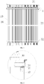
FIG. 1 is a schematic structure diagram of a heat exchanger according to an embodiment of the present disclosure. -
FIG. 2 is a partially enlarged view of A inFIG. 1 . -
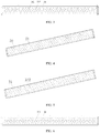
FIG. 3 is a schematic structure diagram of an upper side plate of a heat exchanger according to an embodiment of the present disclosure. -
FIG. 4 is a schematic structure diagram of a first water collecting tank of a heat exchanger according to an embodiment of the present disclosure. -
FIG. 5 is a schematic structure diagram of a second water collecting tank of a heat exchanger according to an embodiment of the present disclosure. -
FIG. 6 is a schematic structure diagram of a lower side plate of a heat exchanger according to an embodiment of the present disclosure. - The reference signs in
FIGS. 1 to 6 respectively represent: 10, heat exchange tube; 20, first water collecting tank; 21, first water diversion hole; 31, second water collecting tank; 312, second water diversion hole; 32, lower side plate; 321, second connection hole; 33, connection plate; 34, upper side plate; 341, drainage hole; 342, mounting hole. - The present disclosure will be further described below in combination with the embodiments. However the present disclosure is not limited to the contents of the description.
- As shown in
FIGS. 1 and4 , the present disclosure provides a heat exchanger including aheat exchange tube 10 and a firstwater collecting tank 20. The firstwater collecting tank 20 is disposed on theheat exchange tube 10. A firstwater diversion hole 21 is provided at a bottom portion of the first water collectingtank 20. Theheat exchange tube 10 passes through the firstwater diversion hole 21, the firstwater diversion hole 21 has a diameter greater than an outer diameter of theheat exchange tube 10, and a gap is formed between the firstwater diversion hole 21 and theheat exchange tube 10. Water flows through the gap and then adheres to an outer wall of theheat exchange tube 10. In the present disclosure, by providing the first water collectingtank 20, and making theheat exchange tube 10 pass through the firstwater diversion hole 21 provided on the first water collectingtank 20, and leaving a gap therebetween, the water (condensate water or cooling water) in the first water collectingtank 20 evenly flows into the firstwater diversion hole 21. Since the gap is smaller, the water flow can pass through the gap, then the water flow can further adhere to theheat exchange tube 10 in the firstwater diversion hole 21 after passing through the gap, which is beneficial to forming a water film on the outer surface of theheat exchange tube 10 and improving the heat exchange efficiency. - When the heat exchanger is a condenser, by providing the first water collecting
tank 20, and making theheat exchange tube 10 pass through the firstwater diversion hole 21 provided on the first water collectingtank 20, and leaving a gap therebetween, the condensate water in the first water collectingtank 20 evenly flows into the firstwater diversion hole 21. Since the gap is smaller, the water flow can pass through the gap, then the water flow can further adhere to theheat exchange tube 10 in the firstwater diversion hole 21 after passing through the gap, which is beneficial to forming a water film on the outer surface of theheat exchange tube 10 and improving the heat exchange efficiency. - As shown in
FIG. 3 , in the above embodiment, the heat exchanger further includes anupper side plate 34. Theupper side plate 34 is located above the first water collectingtank 20. Theupper side plate 34 ir provide with amounting hole 342, and theheat exchange tube 10 expands into the mounting hole. Accordingly, theheat exchange tube 10 which was not fixed can be fixed by theupper side plate 34, so as to avoid abrasions between theheat exchange tube 10 and its adjacent parts during transportation and operation, thereby eliminating a hidden danger of tube abrasion and ensuring a product quality. - In the above embodiment, the
upper side plate 34 is further provided with a drainage structure, and water flows into the first water collectingtank 20 through the drainage structure. The drainage structure has a plurality ofdrainage holes 341. Thedrainage holes 341 are provided on theupper side plate 34 at intervals, and onedrainage hole 341 is provided between every twoadjacent mounting holes 342. The water flow can be evenly distributed into the secondwater collecting tank 31 through thedrainage holes 341. - As shown in
FIG. 6 , in the above embodiment, the heat exchanger further includes anlower side plate 32. Thelower side plate 32 is located below the firstwater collecting tank 20, and asecond connection hole 321 is provided on thelower side plate 32. Theheat exchange tube 10 expands into thesecond connection hole 321. By providing thelower side plate 32 which expands into theheat exchange tube 10, theheat exchange tube 10 can be fixed by thelower side plate 32, so as to avoid abrasions between theheat exchange tube 10 and thelower side plate 32 during transportation and operation, thereby eliminating a hidden danger of tube abrasion and ensuring the product quality. - In the above embodiment, the heat exchanger further includes a
connection plate 33. Theconnection plate 33 is provided between theupper side plate 34 and thelower side plate 32, and two ends of theconnection plate 33 are fixed to theupper side plate 34 and thelower side plate 32 respectively. By providing theconnection plate 33 to connect theupper side plate 34 with thelower side plate 32 as an integral fixing frame, the overall strength of the heat exchanger can be increased, thereby avoiding damages caused by the abrasions between theheat exchange tube 10 and the water collecting tank, and ensuring the product quality. - In the above embodiment, the heat exchanger further includes a second
water collecting tank 31. The secondwater collecting tank 31 is provided on theheat exchange tube 10 and is located above the firstwater collecting tank 20. A secondwater diversion hole 312 is further provided on the secondwater collecting tank 31, and water flows through the secondwater diversion hole 312 into the firstwater collecting tank 20. Since the secondwater diversion hole 312 is provided in the secondwater collecting tank 31, the water that previously only flows along a singleheat exchange tube 10 converges into the secondwater collecting tank 31, and then flows through the secondwater diversion hole 312 into the firstwater collecting tank 20, to form a first water diversion. After the first water diversion, and after the water converges into the firstwater collecting tank 20, since theheat exchange tube 10 is provided in each firstwater diversion hole 21, the water then evenly flows into the firstwater diversion hole 21 and adheres onto theheat exchange tube 10 to form a second water diversion. Through two water diversions, the water is distributed more evenly, such that the amount of condensate water adhering to eachheat exchange tube 10 is more even, then a water film formed on the outer surface of theheat exchange tube 10 is more uniform, thereby further improving the heat exchange efficiency. - In the above embodiment, the
heat exchange tube 10 passes through the secondwater diversion hole 312, and the secondwater diversion hole 312 has a diameter greater than an outer diameter of theheat exchange tube 10, so that a gap is formed between the secondwater diversion hole 312 and theheat exchange tube 10. Water adheres to an outer wall of theheat exchange tube 10 after passing through the gap. The water (condensate water or cooling water) in the secondwater collecting tank 31 evenly flows into the secondwater diversion hole 312. Since the gap is smaller, the water flow can pass through the gap, and then the water flow can adhere to theheat exchange tube 10 in the secondwater diversion hole 312 after the water flow passes through the gap, which is beneficial to forming a water film on the outer surface of theheat exchange tube 10 and improving the heat exchange efficiency. - As shown in
FIG. 5 , in the above embodiment, there are a plurality of second water diversion holes 312, and each secondwater diversion hole 312 is passed through by oneheat exchange tube 10. A difference value between a diameter of the secondwater diversion hole 31 and an outer diameter of theheat exchange tube 10 is in a range of 0.5 mm to 1.5 mm. Accordingly, the water flow can evenly flow into the gap, and the water flow can adhere to theheat exchange tube 10 in the secondwater diversion hole 312 after flowing into the gap, which is beneficial to forming a water film on the outer surface of theheat exchange tube 10 and improving the heat exchange efficiency. - In the above embodiments, a center of the second
water diversion hole 312 is located on an axis of theheat exchange tube 10, so that a uniform gap is formed between outer wall of theheat exchange tube 10 and an inner edge of the secondwater diversion hole 312, to allow the water to more evenly adhere to theheat exchange tube 10 in the secondwater diversion hole 312 when the water flows through the gap, which is more beneficial to the formation of a water film on the outer surface of theheat exchange tube 10, thereby improving the heat exchange efficiency. - As shown in
FIGS. 1 and 2 , in the above embodiment, the secondwater collecting tank 31 is located below theupper side plate 34, theupper side plate 34 covers the secondwater collecting tank 31, and theheat exchange tube 10 expanding to theupper side plate 34 passes through the secondwater collecting tank 31, theconnection plate 33 is provided between the secondwater collecting tank 31 and thelower side plate 32, and two ends of theconnection plate 33 are fixed to the secondwater collecting tank 31 and thelower side plate 32 respectively. The firstwater collecting tank 20 is located between the secondwater collecting tank 31 and thelower side plate 32, and the firstwater collecting tank 20 is fixed to theconnection plate 33. By providing theconnection plate 33 to connect the firstwater collecting tank 20, the secondwater collecting tank 31 and thelower side plate 32 as a whole. On one hand, the overall strength of the heat exchanger can be increased, thereby avoiding the damages caused by the abrasions between theheat exchange tube 10 and the water collecting tank, and ensuring the product quality; on the other hand, the problem of uneven distribution of water flow below the pipelines caused by an overlongheat exchange tube 10 can also be avoided, i.e., the water film can be formed on the outer surface of the heat exchange tube even if the pipeline is longer, thereby improving the heat exchange efficiency. - In the above embodiment, a difference value between a diameter of the first
water diversion hole 21 and an outer diameter of theheat exchange tube 10 is in a range of 0.5 mm to 1.5 mm. Accordingly, the water flow can flow through the gap, and then can adhere to theheat exchange tube 10 in the secondwater diversion hole 21, which is beneficial to form a water film on the outer surface of theheat exchange tube 10, thereby improving the heat exchange efficiency. - In the above embodiment, a center of the first
water diversion hole 21 is located on an axis of theheat exchange tube 10, so that a uniform gap is formed between an outer wall of theheat exchange tube 10 and an inner edge of the firstwater diversion hole 21, to allow the water to more evenly adhere to theheat exchange tube 10 in the firstwater diversion hole 21 when the water flows through the gap, which is more beneficial to the formation of the water film on the outer surface of theheat exchange tube 10, thereby improving the heat exchange efficiency. - In the above embodiment, the heat exchanger further includes a liquid collecting tube and a gas diversion tube. One end of the
heat exchange tube 10 is connected to the gas diversion tube, and the other end of the heat exchange tube is connected to the liquid collecting tube. - In another aspect of the present disclosure, an air conditioner including the above heat exchanger is further provided.
- In another aspect of the present disclosure, a refrigerating unit including the above heat exchanger is further provided.
- It is apparent that the above embodiments of the present disclosure are merely examples for clearly illustrating the present disclosure, rather than limitations to the embodiments of the present disclosure. Other modifications and variations in other different forms can be made by those skilled in the art based on the above description. All of the embodiments are not exhausted. Apparent modifications and variations derived from the technical solution of the present disclosure are all within the scope of protection of the present disclosure.
Claims (16)
- A heat exchanger, comprising a heat exchange tube (10) and a first water collecting tank (20), the first water collecting tank (20) being provided on the heat exchange tube (10), a first water diversion hole (21) being provided at a bottom portion of the first water collecting tank (20), the heat exchange tube (10) passing through the first water diversion hole (21), and the first water diversion hole (21) having a diameter greater than an outer diameter of the heat exchange tube (10).
- The heat exchanger according to claim 1, further comprising an upper side plate (34), wherein the upper side plate (34) is located above the first water collecting tank (20), a mounting hole (342) is provided on the upper side plate (34), and the heat exchange tube (10) is fixedly mounted in the mounting hole (342).
- The heat exchanger according to claim 2, wherein a drainage structure is further provided on the upper side plate (34), and water flows through the drainage structure into the first water collecting tank (20).
- The heat exchanger according to claim 3, wherein the drainage structure has a plurality of drainage holes (341).
- The heat exchanger according to claim 4, wherein the drainage holes (341) are provided on the upper side plate (34) at intervals, and one drainage hole (341) is provided between every two adjacent mounting holes (342).
- The heat exchanger according to claim 2, further comprising a lower side plate (32), wherein the lower side plate (32) is located below the first water collecting tank (20), a second connection hole (321) is provided on the lower side plate (32), and the heat exchange tube (10) is fixedly mounted in the second connection hole (321).
- The heat exchanger according to claim 6, further comprising a connection plate (33), wherein the connection plate (33) is provided between the upper side plate (34) and the lower side plate (32), and two ends of the connection plate (33) are respectively fixed to the upper side plate (34) and the lower side plate (32).
- The heat exchanger according to any one of claims 1 to 7, further comprising a second water collecting tank (31), wherein the second water collecting tank (31) is provided on the heat exchange tube (10) and is located above the first water collecting tank (20), a second water diversion hole (312) is further provided on the second water collecting tank (31), and water flows through the second water diversion hole (312) into the first water collecting tank (20).
- The heat exchanger according to claim 8, wherein the heat exchange tube (10) passes through the second water diversion hole (312), and the second water diversion hole (312) has a diameter greater than an outer diameter of the heat exchange tube (10).
- The heat exchanger according to claim 9, wherein a center of the second water diversion hole (312) is located on an axis of the heat exchange tube (10).
- The heat exchanger according to claim 8, comprising the upper side plate (34), wherein the second water collecting tank (31) is located below the upper side plate (34), and the heat exchange tube (10) expanding to the upper side plate (34) passes through the second water collecting tank (31).
- The heat exchanger according to claim 11, comprising the connection plate (33), wherein the upper side plate (34) covers the second water collecting tank (31), the first water collecting tank (20) is fixed to the connection plate (33), and the second water collecting tank (31) is fixed to the connection plate (33).
- The heat exchanger according to claim 1, wherein a center of the first water diversion hole (21) is located on an axis of the heat exchange tube (10).
- The heat exchanger according to claim 1, further comprising a liquid collecting tube and a gas diversion tube, one end of the heat exchange tube (10) is connected to the gas diversion tube, and the other end of the heat exchange tube (10) is connected to the liquid collecting tube.
- An air conditioner, comprising the heat exchanger according to any one of claims 1 to 14.
- A refrigerating unit, comprising the heat exchanger according to any one of claims 1 to 14.
Applications Claiming Priority (2)
| Application Number | Priority Date | Filing Date | Title |
|---|---|---|---|
| CN201810045147.0A CN108168150B (en) | 2018-01-17 | 2018-01-17 | Heat exchanger, air conditioner and refrigerating unit |
| PCT/CN2018/120269 WO2019141022A1 (en) | 2018-01-17 | 2018-12-11 | Heat exchanger, air conditioner, and cooling unit |
Publications (3)
| Publication Number | Publication Date |
|---|---|
| EP3742083A1 true EP3742083A1 (en) | 2020-11-25 |
| EP3742083A4 EP3742083A4 (en) | 2021-03-03 |
| EP3742083B1 EP3742083B1 (en) | 2022-02-02 |
Family
ID=62514581
Family Applications (1)
| Application Number | Title | Priority Date | Filing Date |
|---|---|---|---|
| EP18901794.0A Active EP3742083B1 (en) | 2018-01-17 | 2018-12-11 | Heat exchanger, air conditioner, and cooling unit |
Country Status (4)
| Country | Link |
|---|---|
| US (1) | US11639817B2 (en) |
| EP (1) | EP3742083B1 (en) |
| CN (1) | CN108168150B (en) |
| WO (1) | WO2019141022A1 (en) |
Families Citing this family (3)
| Publication number | Priority date | Publication date | Assignee | Title |
|---|---|---|---|---|
| CN108168150B (en) | 2018-01-17 | 2019-12-27 | 珠海格力电器股份有限公司 | Heat exchanger, air conditioner and refrigerating unit |
| CN109028541B (en) * | 2018-08-01 | 2020-07-17 | 珠海格力电器股份有限公司 | Heat exchanger and air conditioning system with same |
| CN109737769A (en) * | 2019-02-21 | 2019-05-10 | 珠海格力电器股份有限公司 | Heat exchanger with spray water collecting device and refrigerating unit |
Family Cites Families (16)
| Publication number | Priority date | Publication date | Assignee | Title |
|---|---|---|---|---|
| US4235281A (en) * | 1978-04-07 | 1980-11-25 | The Boeing Company | Condenser/evaporator heat exchange apparatus and method of utilizing the same |
| NL8102024A (en) * | 1981-04-24 | 1982-11-16 | Esmil Bv | FLUID HEAT EXCHANGER - FLUID HEAT EXCHANGE. |
| JPS5862494A (en) | 1981-10-07 | 1983-04-13 | Hitachi Ltd | Evaporative cooler |
| JPS6482590A (en) | 1987-09-24 | 1989-03-28 | Mitsubishi Electric Corp | Manufacture of semiconductor device |
| US5020587A (en) * | 1990-11-01 | 1991-06-04 | Lennox Industries Inc. | Fully floating tube bundle |
| JPH1082590A (en) * | 1996-09-05 | 1998-03-31 | Daikin Ind Ltd | Shell and tube heat exchanger |
| US5893410A (en) * | 1997-06-09 | 1999-04-13 | General Electric Co. | Falling film condensing heat exchanger with liquid film heat transfer |
| JP3091860B1 (en) * | 1999-05-31 | 2000-09-25 | 春男 上原 | Absorber |
| KR100482825B1 (en) * | 2002-07-09 | 2005-04-14 | 삼성전자주식회사 | Heat exchanger |
| KR100482827B1 (en) * | 2002-09-14 | 2005-04-14 | 삼성전자주식회사 | Heat exchanger |
| US20080121384A1 (en) * | 2006-11-29 | 2008-05-29 | Po-Yung Tseng | Liquid cooled heat dissipator |
| CN202350567U (en) * | 2011-12-07 | 2012-07-25 | 四川省宜宾五粮液集团有限公司 | High-efficiency energy-saving integrated condenser |
| CN203629146U (en) * | 2013-09-29 | 2014-06-04 | 长城汽车股份有限公司 | Heat exchanger and automobile with same |
| CN205014697U (en) * | 2015-09-18 | 2016-02-03 | 浙江万享科技股份有限公司 | Evaporative condenser structure |
| CN208012163U (en) * | 2018-01-17 | 2018-10-26 | 珠海格力电器股份有限公司 | heat exchanger, air conditioner and refrigerating unit |
| CN108168150B (en) * | 2018-01-17 | 2019-12-27 | 珠海格力电器股份有限公司 | Heat exchanger, air conditioner and refrigerating unit |
-
2018
- 2018-01-17 CN CN201810045147.0A patent/CN108168150B/en active Active
- 2018-12-11 EP EP18901794.0A patent/EP3742083B1/en active Active
- 2018-12-11 US US16/961,697 patent/US11639817B2/en active Active
- 2018-12-11 WO PCT/CN2018/120269 patent/WO2019141022A1/en not_active Ceased
Also Published As
| Publication number | Publication date |
|---|---|
| WO2019141022A1 (en) | 2019-07-25 |
| CN108168150A (en) | 2018-06-15 |
| EP3742083A4 (en) | 2021-03-03 |
| CN108168150B (en) | 2019-12-27 |
| US20210080158A1 (en) | 2021-03-18 |
| US11639817B2 (en) | 2023-05-02 |
| EP3742083B1 (en) | 2022-02-02 |
Similar Documents
| Publication | Publication Date | Title |
|---|---|---|
| US11639817B2 (en) | Heat exchanger, air conditioner, and refrigerating unit | |
| US8561680B2 (en) | Heat exchanger | |
| CN205690935U (en) | Shell-and-tube heat exchanger based on segmental baffle | |
| EP3087335B1 (en) | Distributor for falling film evaporator | |
| CN110285691A (en) | Finned tube heat exchanger, evaporative condenser and refrigerating unit | |
| US10704844B2 (en) | Heat exchanger | |
| CN208795040U (en) | A kind of ring wing formula endless tube gas-liquid heat-exchange | |
| CN106855367A (en) | Shell-and-tube heat exchanger with distributivity gateway | |
| CN220541224U (en) | Heat exchanger assembly and American air duct machine | |
| CN204115533U (en) | A kind of vertical (type) condenser | |
| CN104165540A (en) | Open circulating water gas-liquid orthogonal membrane plate air cooler | |
| CN108759514B (en) | Liquid homogenizer for shell and tube heat exchanger and shell and tube heat exchanger | |
| CN104949395A (en) | Heat pump type microchannel heat exchanger | |
| JP7618016B2 (en) | Assembled Heat Exchanger | |
| CN204574636U (en) | A kind of blown plate type condenser | |
| CN109340930A (en) | A water receiving tray and an air conditioner outdoor unit having the same | |
| CN208012163U (en) | heat exchanger, air conditioner and refrigerating unit | |
| CN103743268B (en) | tubular heat exchanger with blocking device | |
| CN224074994U (en) | A static pressure box with uniform horizontal airflow | |
| CN208567605U (en) | A kind of plate heat exchanger for exchanging heat between gas-liquid | |
| CN207716691U (en) | A kind of shell-and-tube evaporator | |
| CN205385375U (en) | Air cooler for motor | |
| CN204963645U (en) | Plate structure and have its evaporimeter inner bag and condenser curb plate | |
| CN220524336U (en) | Heat preservation tuber pipe | |
| CN218154910U (en) | High-efficient heat transfer device of refrigeration plant |
Legal Events
| Date | Code | Title | Description |
|---|---|---|---|
| STAA | Information on the status of an ep patent application or granted ep patent |
Free format text: STATUS: THE INTERNATIONAL PUBLICATION HAS BEEN MADE |
|
| PUAI | Public reference made under article 153(3) epc to a published international application that has entered the european phase |
Free format text: ORIGINAL CODE: 0009012 |
|
| STAA | Information on the status of an ep patent application or granted ep patent |
Free format text: STATUS: REQUEST FOR EXAMINATION WAS MADE |
|
| 17P | Request for examination filed |
Effective date: 20200708 |
|
| AK | Designated contracting states |
Kind code of ref document: A1 Designated state(s): AL AT BE BG CH CY CZ DE DK EE ES FI FR GB GR HR HU IE IS IT LI LT LU LV MC MK MT NL NO PL PT RO RS SE SI SK SM TR |
|
| AX | Request for extension of the european patent |
Extension state: BA ME |
|
| A4 | Supplementary search report drawn up and despatched |
Effective date: 20210201 |
|
| RIC1 | Information provided on ipc code assigned before grant |
Ipc: F25B 39/00 20060101AFI20210126BHEP |
|
| DAV | Request for validation of the european patent (deleted) | ||
| DAX | Request for extension of the european patent (deleted) | ||
| GRAP | Despatch of communication of intention to grant a patent |
Free format text: ORIGINAL CODE: EPIDOSNIGR1 |
|
| STAA | Information on the status of an ep patent application or granted ep patent |
Free format text: STATUS: GRANT OF PATENT IS INTENDED |
|
| INTG | Intention to grant announced |
Effective date: 20210719 |
|
| GRAS | Grant fee paid |
Free format text: ORIGINAL CODE: EPIDOSNIGR3 |
|
| GRAA | (expected) grant |
Free format text: ORIGINAL CODE: 0009210 |
|
| STAA | Information on the status of an ep patent application or granted ep patent |
Free format text: STATUS: THE PATENT HAS BEEN GRANTED |
|
| AK | Designated contracting states |
Kind code of ref document: B1 Designated state(s): AL AT BE BG CH CY CZ DE DK EE ES FI FR GB GR HR HU IE IS IT LI LT LU LV MC MK MT NL NO PL PT RO RS SE SI SK SM TR |
|
| REG | Reference to a national code |
Ref country code: GB Ref legal event code: FG4D |
|
| REG | Reference to a national code |
Ref country code: CH Ref legal event code: EP Ref country code: AT Ref legal event code: REF Ref document number: 1466677 Country of ref document: AT Kind code of ref document: T Effective date: 20220215 |
|
| REG | Reference to a national code |
Ref country code: DE Ref legal event code: R096 Ref document number: 602018030474 Country of ref document: DE |
|
| REG | Reference to a national code |
Ref country code: IE Ref legal event code: FG4D |
|
| REG | Reference to a national code |
Ref country code: LT Ref legal event code: MG9D |
|
| REG | Reference to a national code |
Ref country code: NL Ref legal event code: MP Effective date: 20220202 |
|
| REG | Reference to a national code |
Ref country code: AT Ref legal event code: MK05 Ref document number: 1466677 Country of ref document: AT Kind code of ref document: T Effective date: 20220202 |
|
| PG25 | Lapsed in a contracting state [announced via postgrant information from national office to epo] |
Ref country code: SE Free format text: LAPSE BECAUSE OF FAILURE TO SUBMIT A TRANSLATION OF THE DESCRIPTION OR TO PAY THE FEE WITHIN THE PRESCRIBED TIME-LIMIT Effective date: 20220202 Ref country code: RS Free format text: LAPSE BECAUSE OF FAILURE TO SUBMIT A TRANSLATION OF THE DESCRIPTION OR TO PAY THE FEE WITHIN THE PRESCRIBED TIME-LIMIT Effective date: 20220202 Ref country code: PT Free format text: LAPSE BECAUSE OF FAILURE TO SUBMIT A TRANSLATION OF THE DESCRIPTION OR TO PAY THE FEE WITHIN THE PRESCRIBED TIME-LIMIT Effective date: 20220602 Ref country code: NO Free format text: LAPSE BECAUSE OF FAILURE TO SUBMIT A TRANSLATION OF THE DESCRIPTION OR TO PAY THE FEE WITHIN THE PRESCRIBED TIME-LIMIT Effective date: 20220502 Ref country code: NL Free format text: LAPSE BECAUSE OF FAILURE TO SUBMIT A TRANSLATION OF THE DESCRIPTION OR TO PAY THE FEE WITHIN THE PRESCRIBED TIME-LIMIT Effective date: 20220202 Ref country code: LT Free format text: LAPSE BECAUSE OF FAILURE TO SUBMIT A TRANSLATION OF THE DESCRIPTION OR TO PAY THE FEE WITHIN THE PRESCRIBED TIME-LIMIT Effective date: 20220202 Ref country code: HR Free format text: LAPSE BECAUSE OF FAILURE TO SUBMIT A TRANSLATION OF THE DESCRIPTION OR TO PAY THE FEE WITHIN THE PRESCRIBED TIME-LIMIT Effective date: 20220202 Ref country code: ES Free format text: LAPSE BECAUSE OF FAILURE TO SUBMIT A TRANSLATION OF THE DESCRIPTION OR TO PAY THE FEE WITHIN THE PRESCRIBED TIME-LIMIT Effective date: 20220202 Ref country code: BG Free format text: LAPSE BECAUSE OF FAILURE TO SUBMIT A TRANSLATION OF THE DESCRIPTION OR TO PAY THE FEE WITHIN THE PRESCRIBED TIME-LIMIT Effective date: 20220502 |
|
| PG25 | Lapsed in a contracting state [announced via postgrant information from national office to epo] |
Ref country code: PL Free format text: LAPSE BECAUSE OF FAILURE TO SUBMIT A TRANSLATION OF THE DESCRIPTION OR TO PAY THE FEE WITHIN THE PRESCRIBED TIME-LIMIT Effective date: 20220202 Ref country code: LV Free format text: LAPSE BECAUSE OF FAILURE TO SUBMIT A TRANSLATION OF THE DESCRIPTION OR TO PAY THE FEE WITHIN THE PRESCRIBED TIME-LIMIT Effective date: 20220202 Ref country code: GR Free format text: LAPSE BECAUSE OF FAILURE TO SUBMIT A TRANSLATION OF THE DESCRIPTION OR TO PAY THE FEE WITHIN THE PRESCRIBED TIME-LIMIT Effective date: 20220503 Ref country code: FI Free format text: LAPSE BECAUSE OF FAILURE TO SUBMIT A TRANSLATION OF THE DESCRIPTION OR TO PAY THE FEE WITHIN THE PRESCRIBED TIME-LIMIT Effective date: 20220202 Ref country code: AT Free format text: LAPSE BECAUSE OF FAILURE TO SUBMIT A TRANSLATION OF THE DESCRIPTION OR TO PAY THE FEE WITHIN THE PRESCRIBED TIME-LIMIT Effective date: 20220202 |
|
| PG25 | Lapsed in a contracting state [announced via postgrant information from national office to epo] |
Ref country code: IS Free format text: LAPSE BECAUSE OF FAILURE TO SUBMIT A TRANSLATION OF THE DESCRIPTION OR TO PAY THE FEE WITHIN THE PRESCRIBED TIME-LIMIT Effective date: 20220602 |
|
| PG25 | Lapsed in a contracting state [announced via postgrant information from national office to epo] |
Ref country code: SM Free format text: LAPSE BECAUSE OF FAILURE TO SUBMIT A TRANSLATION OF THE DESCRIPTION OR TO PAY THE FEE WITHIN THE PRESCRIBED TIME-LIMIT Effective date: 20220202 Ref country code: SK Free format text: LAPSE BECAUSE OF FAILURE TO SUBMIT A TRANSLATION OF THE DESCRIPTION OR TO PAY THE FEE WITHIN THE PRESCRIBED TIME-LIMIT Effective date: 20220202 Ref country code: RO Free format text: LAPSE BECAUSE OF FAILURE TO SUBMIT A TRANSLATION OF THE DESCRIPTION OR TO PAY THE FEE WITHIN THE PRESCRIBED TIME-LIMIT Effective date: 20220202 Ref country code: EE Free format text: LAPSE BECAUSE OF FAILURE TO SUBMIT A TRANSLATION OF THE DESCRIPTION OR TO PAY THE FEE WITHIN THE PRESCRIBED TIME-LIMIT Effective date: 20220202 Ref country code: DK Free format text: LAPSE BECAUSE OF FAILURE TO SUBMIT A TRANSLATION OF THE DESCRIPTION OR TO PAY THE FEE WITHIN THE PRESCRIBED TIME-LIMIT Effective date: 20220202 Ref country code: CZ Free format text: LAPSE BECAUSE OF FAILURE TO SUBMIT A TRANSLATION OF THE DESCRIPTION OR TO PAY THE FEE WITHIN THE PRESCRIBED TIME-LIMIT Effective date: 20220202 |
|
| REG | Reference to a national code |
Ref country code: DE Ref legal event code: R097 Ref document number: 602018030474 Country of ref document: DE |
|
| PG25 | Lapsed in a contracting state [announced via postgrant information from national office to epo] |
Ref country code: AL Free format text: LAPSE BECAUSE OF FAILURE TO SUBMIT A TRANSLATION OF THE DESCRIPTION OR TO PAY THE FEE WITHIN THE PRESCRIBED TIME-LIMIT Effective date: 20220202 |
|
| PLBE | No opposition filed within time limit |
Free format text: ORIGINAL CODE: 0009261 |
|
| STAA | Information on the status of an ep patent application or granted ep patent |
Free format text: STATUS: NO OPPOSITION FILED WITHIN TIME LIMIT |
|
| 26N | No opposition filed |
Effective date: 20221103 |
|
| PG25 | Lapsed in a contracting state [announced via postgrant information from national office to epo] |
Ref country code: SI Free format text: LAPSE BECAUSE OF FAILURE TO SUBMIT A TRANSLATION OF THE DESCRIPTION OR TO PAY THE FEE WITHIN THE PRESCRIBED TIME-LIMIT Effective date: 20220202 |
|
| P01 | Opt-out of the competence of the unified patent court (upc) registered |
Effective date: 20230530 |
|
| PG25 | Lapsed in a contracting state [announced via postgrant information from national office to epo] |
Ref country code: IT Free format text: LAPSE BECAUSE OF FAILURE TO SUBMIT A TRANSLATION OF THE DESCRIPTION OR TO PAY THE FEE WITHIN THE PRESCRIBED TIME-LIMIT Effective date: 20220202 |
|
| REG | Reference to a national code |
Ref country code: CH Ref legal event code: PL |
|
| REG | Reference to a national code |
Ref country code: BE Ref legal event code: MM Effective date: 20221231 |
|
| PG25 | Lapsed in a contracting state [announced via postgrant information from national office to epo] |
Ref country code: LU Free format text: LAPSE BECAUSE OF NON-PAYMENT OF DUE FEES Effective date: 20221211 |
|
| PG25 | Lapsed in a contracting state [announced via postgrant information from national office to epo] |
Ref country code: LI Free format text: LAPSE BECAUSE OF NON-PAYMENT OF DUE FEES Effective date: 20221231 Ref country code: IE Free format text: LAPSE BECAUSE OF NON-PAYMENT OF DUE FEES Effective date: 20221211 Ref country code: CH Free format text: LAPSE BECAUSE OF NON-PAYMENT OF DUE FEES Effective date: 20221231 |
|
| PG25 | Lapsed in a contracting state [announced via postgrant information from national office to epo] |
Ref country code: BE Free format text: LAPSE BECAUSE OF NON-PAYMENT OF DUE FEES Effective date: 20221231 |
|
| PG25 | Lapsed in a contracting state [announced via postgrant information from national office to epo] |
Ref country code: CY Free format text: LAPSE BECAUSE OF FAILURE TO SUBMIT A TRANSLATION OF THE DESCRIPTION OR TO PAY THE FEE WITHIN THE PRESCRIBED TIME-LIMIT Effective date: 20220202 |
|
| PG25 | Lapsed in a contracting state [announced via postgrant information from national office to epo] |
Ref country code: MK Free format text: LAPSE BECAUSE OF FAILURE TO SUBMIT A TRANSLATION OF THE DESCRIPTION OR TO PAY THE FEE WITHIN THE PRESCRIBED TIME-LIMIT Effective date: 20220202 Ref country code: HU Free format text: LAPSE BECAUSE OF FAILURE TO SUBMIT A TRANSLATION OF THE DESCRIPTION OR TO PAY THE FEE WITHIN THE PRESCRIBED TIME-LIMIT; INVALID AB INITIO Effective date: 20181211 |
|
| PG25 | Lapsed in a contracting state [announced via postgrant information from national office to epo] |
Ref country code: MC Free format text: LAPSE BECAUSE OF FAILURE TO SUBMIT A TRANSLATION OF THE DESCRIPTION OR TO PAY THE FEE WITHIN THE PRESCRIBED TIME-LIMIT Effective date: 20220202 |
|
| PG25 | Lapsed in a contracting state [announced via postgrant information from national office to epo] |
Ref country code: MC Free format text: LAPSE BECAUSE OF FAILURE TO SUBMIT A TRANSLATION OF THE DESCRIPTION OR TO PAY THE FEE WITHIN THE PRESCRIBED TIME-LIMIT Effective date: 20220202 |
|
| PG25 | Lapsed in a contracting state [announced via postgrant information from national office to epo] |
Ref country code: MT Free format text: LAPSE BECAUSE OF FAILURE TO SUBMIT A TRANSLATION OF THE DESCRIPTION OR TO PAY THE FEE WITHIN THE PRESCRIBED TIME-LIMIT Effective date: 20220202 |
|
| PG25 | Lapsed in a contracting state [announced via postgrant information from national office to epo] |
Ref country code: TR Free format text: LAPSE BECAUSE OF FAILURE TO SUBMIT A TRANSLATION OF THE DESCRIPTION OR TO PAY THE FEE WITHIN THE PRESCRIBED TIME-LIMIT Effective date: 20220202 |
|
| PGFP | Annual fee paid to national office [announced via postgrant information from national office to epo] |
Ref country code: GB Payment date: 20251111 Year of fee payment: 8 |
|
| PGFP | Annual fee paid to national office [announced via postgrant information from national office to epo] |
Ref country code: FR Payment date: 20251110 Year of fee payment: 8 |
|
| PGFP | Annual fee paid to national office [announced via postgrant information from national office to epo] |
Ref country code: DE Payment date: 20251222 Year of fee payment: 8 |