EP3741986A1 - Actuator for actuating a control body of an internal combustion engine - Google Patents
Actuator for actuating a control body of an internal combustion engine Download PDFInfo
- Publication number
- EP3741986A1 EP3741986A1 EP20175174.0A EP20175174A EP3741986A1 EP 3741986 A1 EP3741986 A1 EP 3741986A1 EP 20175174 A EP20175174 A EP 20175174A EP 3741986 A1 EP3741986 A1 EP 3741986A1
- Authority
- EP
- European Patent Office
- Prior art keywords
- actuator
- housing
- spiral spring
- internal combustion
- combustion engine
- Prior art date
- Legal status (The legal status is an assumption and is not a legal conclusion. Google has not performed a legal analysis and makes no representation as to the accuracy of the status listed.)
- Pending
Links
Images


Classifications
-
- F—MECHANICAL ENGINEERING; LIGHTING; HEATING; WEAPONS; BLASTING
- F02—COMBUSTION ENGINES; HOT-GAS OR COMBUSTION-PRODUCT ENGINE PLANTS
- F02M—SUPPLYING COMBUSTION ENGINES IN GENERAL WITH COMBUSTIBLE MIXTURES OR CONSTITUENTS THEREOF
- F02M26/00—Engine-pertinent apparatus for adding exhaust gases to combustion-air, main fuel or fuel-air mixture, e.g. by exhaust gas recirculation [EGR] systems
- F02M26/52—Systems for actuating EGR valves
- F02M26/53—Systems for actuating EGR valves using electric actuators, e.g. solenoids
- F02M26/54—Rotary actuators, e.g. step motors
-
- F—MECHANICAL ENGINEERING; LIGHTING; HEATING; WEAPONS; BLASTING
- F02—COMBUSTION ENGINES; HOT-GAS OR COMBUSTION-PRODUCT ENGINE PLANTS
- F02M—SUPPLYING COMBUSTION ENGINES IN GENERAL WITH COMBUSTIBLE MIXTURES OR CONSTITUENTS THEREOF
- F02M26/00—Engine-pertinent apparatus for adding exhaust gases to combustion-air, main fuel or fuel-air mixture, e.g. by exhaust gas recirculation [EGR] systems
- F02M26/65—Constructional details of EGR valves
- F02M26/70—Flap valves; Rotary valves; Sliding valves; Resilient valves
-
- F—MECHANICAL ENGINEERING; LIGHTING; HEATING; WEAPONS; BLASTING
- F16—ENGINEERING ELEMENTS AND UNITS; GENERAL MEASURES FOR PRODUCING AND MAINTAINING EFFECTIVE FUNCTIONING OF MACHINES OR INSTALLATIONS; THERMAL INSULATION IN GENERAL
- F16F—SPRINGS; SHOCK-ABSORBERS; MEANS FOR DAMPING VIBRATION
- F16F1/00—Springs
- F16F1/02—Springs made of steel or other material having low internal friction; Wound, torsion, leaf, cup, ring or the like springs, the material of the spring not being relevant
- F16F1/04—Wound springs
- F16F1/041—Wound springs with means for modifying the spring characteristics
-
- F—MECHANICAL ENGINEERING; LIGHTING; HEATING; WEAPONS; BLASTING
- F16—ENGINEERING ELEMENTS AND UNITS; GENERAL MEASURES FOR PRODUCING AND MAINTAINING EFFECTIVE FUNCTIONING OF MACHINES OR INSTALLATIONS; THERMAL INSULATION IN GENERAL
- F16F—SPRINGS; SHOCK-ABSORBERS; MEANS FOR DAMPING VIBRATION
- F16F1/00—Springs
- F16F1/02—Springs made of steel or other material having low internal friction; Wound, torsion, leaf, cup, ring or the like springs, the material of the spring not being relevant
- F16F1/04—Wound springs
- F16F1/10—Spiral springs with turns lying substantially in plane surfaces
-
- F—MECHANICAL ENGINEERING; LIGHTING; HEATING; WEAPONS; BLASTING
- F16—ENGINEERING ELEMENTS AND UNITS; GENERAL MEASURES FOR PRODUCING AND MAINTAINING EFFECTIVE FUNCTIONING OF MACHINES OR INSTALLATIONS; THERMAL INSULATION IN GENERAL
- F16K—VALVES; TAPS; COCKS; ACTUATING-FLOATS; DEVICES FOR VENTING OR AERATING
- F16K31/00—Actuating devices; Operating means; Releasing devices
- F16K31/02—Actuating devices; Operating means; Releasing devices electric; magnetic
- F16K31/04—Actuating devices; Operating means; Releasing devices electric; magnetic using a motor
- F16K31/047—Actuating devices; Operating means; Releasing devices electric; magnetic using a motor characterised by mechanical means between the motor and the valve, e.g. lost motion means reducing backlash, clutches, brakes or return means
-
- F—MECHANICAL ENGINEERING; LIGHTING; HEATING; WEAPONS; BLASTING
- F16—ENGINEERING ELEMENTS AND UNITS; GENERAL MEASURES FOR PRODUCING AND MAINTAINING EFFECTIVE FUNCTIONING OF MACHINES OR INSTALLATIONS; THERMAL INSULATION IN GENERAL
- F16F—SPRINGS; SHOCK-ABSORBERS; MEANS FOR DAMPING VIBRATION
- F16F1/00—Springs
- F16F1/02—Springs made of steel or other material having low internal friction; Wound, torsion, leaf, cup, ring or the like springs, the material of the spring not being relevant
- F16F1/04—Wound springs
- F16F1/12—Attachments or mountings
- F16F1/123—Attachments or mountings characterised by the ends of the spring being specially adapted, e.g. to form an eye for engagement with a radial insert
-
- Y—GENERAL TAGGING OF NEW TECHNOLOGICAL DEVELOPMENTS; GENERAL TAGGING OF CROSS-SECTIONAL TECHNOLOGIES SPANNING OVER SEVERAL SECTIONS OF THE IPC; TECHNICAL SUBJECTS COVERED BY FORMER USPC CROSS-REFERENCE ART COLLECTIONS [XRACs] AND DIGESTS
- Y02—TECHNOLOGIES OR APPLICATIONS FOR MITIGATION OR ADAPTATION AGAINST CLIMATE CHANGE
- Y02T—CLIMATE CHANGE MITIGATION TECHNOLOGIES RELATED TO TRANSPORTATION
- Y02T10/00—Road transport of goods or passengers
- Y02T10/10—Internal combustion engine [ICE] based vehicles
- Y02T10/12—Improving ICE efficiencies
Definitions
- the invention relates to an actuator for actuating a control body of an internal combustion engine with a housing, an electric motor arranged in the housing with a rotor and a stator, a cover that can be attached to the housing, a rotatable shaft that is at least rotationally fixed to the rotor, and one in the housing fixed spiral spring wound in one plane.
- electromagnetically operated actuators are used in particular in valve devices of internal combustion engines for recirculating exhaust gases into the intake tract of the internal combustion engine.
- other applications such as those for heat recovery for heating purposes in a passenger compartment, are also conceivable.
- the spiral spring which is fastened in such actuators or valve devices, fulfills a so-called fail-safe function. If there is a technical defect in the electric motor or if the power supply to the actuator fails, mechanically stored and sufficiently large energy in the spiral spring built up by preloading the spring ensures that the valve rotates into a defined position, so that the functionality of the internal combustion engine is not as possible is restricted.
- Such coil springs are for example in FR 1238445 and WO 88/07625 disclosed.
- the task is therefore to ensure a guided movement of the spiral spring with as little friction as possible and to avoid malfunctions.
- an actuator for a regulating body with the features of main claim 1.
- a friction-reducing element for the spiral spring is arranged on the housing means that the contact between individual segments of the spiral spring is at least partially eliminated, whereby the internal friction work of the spiral spring is reduced.
- the friction reduction element also helps to keep the individual spring segments in a largely constant position, which limits the position of the spring to such an extent that the spring in the housing can no longer get caught on projections, edges or other components of the actuator such as the cover .
- the friction reduction element is designed as an axial projection in the housing and in one piece with the housing.
- the spiral spring is at least partially in an intermediate space between the actuator housing and the radial further internally arranged friction reduction element out. Because the friction reduction element is formed in one piece with the actuator housing, there is no need for a friction reduction element as a separate component.
- the friction reduction element can have an elongated component in the circumferential direction of the actuator housing. As a result, the segments of the spiral spring are reliably kept at a distance from one another over a longer distance.
- the friction-reducing element has a leg which engages between turns of the spiral spring. This ensures that the distance between individual turns is preserved and mechanical contact is prevented, at least in the area of the leg of the friction-reducing element.
- the friction reducing element is U-shaped and has two axial legs.
- the first axial leg engages between the two outer segments of the spiral spring and prevents contact between the two outer segments, as a result of which the internal friction of the spiral spring is reduced.
- the second axial leg is in the housing of the actuator.
- a rotatably mounted friction reduction roller is arranged on the first axial leg of the friction reduction element or on the axial projection on the housing.
- the friction reduction roller can be rotatably mounted on the friction reduction element, for example by means of an elastic plug connection, and reduces the friction between individual turns of the spiral spring to a higher degree than a friction reduction element without a friction reduction roller, since the friction reduction roller supports a relative movement of the segments of the spiral spring by its own movement or by rolling.
- the friction reduction element has a plurality of first axial legs.
- the first axial legs engage between the turns of the spiral spring and ensure the spacing between spiral spring segments over a longer distance either next to one another in the circumferential direction of the first legs or one behind the other between different turns in the radial direction. In this way, the work of friction of the spiral spring is reduced more efficiently, since the contact is prevented over a greater distance along the spiral spring.
- the spring deformation takes place in a more controlled and orderly manner than by holding it at a single point.
- a connecting section is formed between two first legs of the friction reduction element.
- This connecting section is at least partially arranged in a form-fitting manner in a recess of the housing.
- the form fit ensures that the friction-reducing element is at least partially deprived of the possibility of movement. For example, it cannot move in the radial direction. Only a movement in the axial direction of the actuator would be possible if this were not prevented, for example, by the cover of the actuator.
- a region of the friction reduction element connecting the at least one first limb and the at least one second limb is at least partially in a recess on the Housing led.
- the recess on the housing removes at least one further degree of freedom from the friction reduction element as a result of a form fit and, in conjunction with the at least one second leg that is inserted into the actuator housing, helps it to be fixed in a plane which is parallel to the plane of the spiral spring and perpendicular to the axis of the Actuator is arranged to ensure. Neither a translational nor a rotational movement of the friction-reducing element is possible within this plane.
- the spiral spring is preferably fastened directly to the housing at a first of its two ends.
- the fastening takes place via form fit. Since the housing is static, this fastening creates the basis for a relative movement of the two spring ends or for the deformation of the spiral spring.
- the spiral spring has a first end bent by at least 110 °. This is inserted behind a corresponding housing projection or surrounds this housing projection.
- the housing projection extends both in the circumferential and in the axial direction. Advantages of bent ends of the spiral spring are simple assembly, the need for additional fastening elements such as rings, pins, clamps, adhesives or the like, and reliable fastening.
- a second end of the spiral spring is attached to an axial projection formed on the rotor.
- a rotor is understood to mean all rotating parts of the electric motor including the shaft or a return ring or a pole disc in axial flux motors. At this second end, too, it is fastened by means of a form fit. Because the rotor is movable, and against the backdrop of the most static Housing attached first end of the spiral spring, the spiral spring can be pretensioned and tensioned in this arrangement by energizing the actuator.
- the second end of the spiral spring is preferably bent by at least 110 ° analogously to the first end of the spiral spring.
- the second end is fastened to a spring retaining pin or engages around it, the spring retaining pin being axially aligned and formed in one piece with a rotating circular return ring.
- the rotor has a spring guide pin.
- a spring guide pin prevents the spiral spring from being excessively offset radially inward in the actuator housing when the spiral spring is contracted concentrically inwards, with deformation. This ensures that the spiral spring is loaded in an orderly and controlled manner.
- an assembly stop is formed in the cover of the actuator. This assembly stop can be used to preload the spiral spring and simplify the assembly process.
- the assembly stop preferably rests against the spring guide pin formed on the rotor when the spiral spring is pretensioned before the control body is fastened to the actuator shaft.
- the spring guide pin acts as a stop for the assembly stop, so that the preloaded spiral spring cannot move into its rest position in which it is relieved.
- the preload of the spiral spring helps to ensure that a a sufficiently large restoring force or energy is stored in the spiral spring to ensure the fail-safe function of the actuator. Starting from this position, the spiral spring is further pretensioned in order to fasten the regulating body.
- An advantageous embodiment of the assembly stop is when it is designed as a bolt which protrudes axially into the housing of the actuator from the inside of the cover.
- the cover is aligned and screwed to the housing in such a way that the bolt rests on the spring guide pin under the pretension of the spiral spring.
- the contact of the spring guide pin on the bolt allows the return ring to rotate in only one direction.
- the static bolt prevents the rotor comprising the return ring from moving in the opposite direction.
- the assembly stop which is designed as a bolt, is preferably made from a plastic and formed in one piece with the cover. Such a configuration enables the cover to be manufactured in a simple manner, for example in an injection molding process. This also reduces the number of components in the actuator.
- the bolt acting as an assembly stop is made of steel and inserted into the cover.
- a steel bolt ensures the fatigue strength of the assembly stop.
- An actuator for a control element of an internal combustion engine is thus created which ensures low friction and dissipation in the coil spring of the actuator, which performs a fail-safe function.
- the spiral spring is guided in a controlled manner during its deformation by means of the friction reduction element. In this way, the risk of the coil spring becoming attached to other components in the To catch the actuator housing or jump out of its storage position, reduced.
- the in Figure 1 The actuator 10 according to the invention shown is arranged in a housing 20, which in turn consists of a flow housing 22, in which a flow channel 26 is formed, and an actuator housing 24 consists.
- the flow housing 22 and the actuator housing 24 are screwed together.
- the actuator 10 comprises an electric motor 11 in a special design, a so-called axial flux motor.
- This comprises a rotor 12 and a stator 14 which are arranged axially spaced apart from one another, the magnetic flux generating the movement also running at least partially in the axial direction.
- Rotating components of the actuator 10 and thus associated with the rotor 12 are a shaft 16, a return ring 17 and an annular, multi-pole and sector-shaped magnetized rotor magnet 18.
- the rotor magnet 18 is glued to the return ring 17.
- the return ring 17 is in turn glued to the shaft 16 at its central radial bore, so that the unit made up of the return ring 17 and rotor magnet 18 always rotates with the shaft 16.
- a sensor magnet 19 is according to Figure 1 arranged at the upper end of the shaft 16 in a recess formed on the end face of the shaft 16 and likewise always rotates with the shaft 16.
- the shaft 16 extends axially through the actuator housing 24 and emerges from the actuator housing 24 via an opening in the actuator housing 24 and protrudes into the flow housing 22 or into a flow channel 26.
- a seal 28 surrounding the shaft 16 is arranged in the transition area between the flow housing 22 and the actuator housing 24, the lip geometry of which ensures a seal between the flow housing 22 and the actuator housing 24.
- the stator 14 comprises a winding 36 that can be energized to generate a magnetic field, as well as a sheet metal core 38 that is fastened in the housing 20. Via a plain bearing bushing 40, the stator 14 is from the Movement of the shaft 16, which is mounted in the plain bearing bush 40, is decoupled.
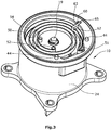
- a cover 30 of the actuator 10 made of plastic comprises an in Figure 2 shown plug 32 as well as electronic components for controlling or actuating the actuator 10.
- a sensor 34 which is attached to the cover 30, interacts with the sensor magnet 19 to detect the position of the shaft 16 of the actuator 10 and thus to detect the position of an actuator in operation with the shaft 16 connected control body 27, which is arranged in the flow housing 22 and is used to regulate the flow cross-section.
- the cover 30 has an assembly stop 42, which is designed as a bolt and projects axially out of the cover 30 and into the actuator housing 24.
- the assembly stop 42 is formed in one piece with the cover 30.
- two axial mounting bolts 44 are formed on the actuator housing 24, which support the positioning and fastening of the cover 30 during its mounting on the actuator housing 24.
- two holes 31 are formed in the cover 30, which define the rotational position of the cover 30.
- two axially extending contact lugs 46 are formed on the cover 30.
- electrical connections 48 are arranged on the actuator housing 24, which ensure the power supply to the stator 14 or the windings 36 of the stator 14.
- a spiral spring 50 which is made from a flat strip metal wound in one plane, is arranged axially between the return ring 17 and the cover 30 of the actuator 10 and radially at least largely within the actuator housing 24.
- the spiral spring 50 is bent by approximately 170 ° and fastened to the actuator housing 24 in a form-fitting manner, as Figure 3 can be found.
- the first end of the spiral spring 50 is behind a projection formed on the actuator housing 24 51, which has a component extending in the circumferential and axial directions, respectively.
- the spiral spring 50 is positively connected to the rotor 12 or to the return ring 17.
- the second end of the spiral spring 50 engages around a spring retaining pin 52, which is designed as an axial projection on the return ring 17.
- the wrap angle of the second bent end is also about 170 °.
- the return ring 17 has, parallel to the spring retaining pin 52, a spring guide pin 54 which is also designed as an axial projection and in one piece with the return ring 17.
- the spring guide pin 54 is spaced from the spring retaining pin 52 by approximately 90 ° in the circumferential direction.
- the spiral spring 50 is arranged at a distance from the spring guide pin 54 in the radial direction.
- the spring guide pin 54 ensures an orderly movement and improved positional stability of the spiral spring 50 when the spiral spring 50 is pretensioned and tensioned, since it restricts the spiral spring 50 from being offset radially inward.
- the spiral spring 50 is hereby prevented from executing any movements and is positioned and guided overall in a more controlled manner when actuators are actuated.
- FIG. 3 , Figure 4 and Figure 5 disclose a first embodiment of a friction reducing element 60 which is U-shaped.
- the friction reduction element 60 consists of a first axially directed leg 62 which engages between the two outermost segments of the spiral spring 50 and a second axially directed leg 64, the second leg 64 being inserted into the actuator housing 24 and the friction reduction element 60 in a movement perpendicular to the Axial direction of the actuator 10 prevents.
- a connecting section 63 of the friction reduction element 60 which is formed between the first leg 62 and the second leg 64 and is at least partially arranged in a recess 65 in the actuator housing 24, thus prevents a rotational movement of the friction reduction element 60 about the vertical axis of the second leg 64 and an axial movement of the spiral spring 50.
- the second leg 64 and the recess 65 in the actuator housing 24 thereby prevent any movements of the friction reducing element 60 within a plane which is arranged orthogonally to the axis of the actuator 10.
- the first leg 62 engaging between the two outer segments of the spiral spring 50 ensures that the outer segments of the spiral spring 50 remain spaced from one another at all times and thus cannot rub against one another. This reduces both the internal frictional moments of the spiral spring 50 and an associated dissipation.
- the energy consumption of the actuator 10 is slightly, but still reduced compared to an actuator 10 without a friction reduction element 60.
- the first leg 62 or the friction reduction element 60 in analogy to the spring guide pin 54, guides the spiral spring 50 and thus also makes a contribution for the orderly and controlled pre-tensioning and tensioning of the spiral spring 50.
- FIG Figure 6 An alternative embodiment of the friction reduction element 60 'is shown in FIG Figure 6 shown.
- two first legs 62 ' engage between the two outer segments of the spiral spring 50.
- the effects brought about by the friction-reducing element 60' are the same as the two effects caused by the friction-reducing element 60.
- the self-friction torque of the spiral spring 50 is reduced and on the other hand, guidance and controlled tensioning of the spiral spring 50 is ensured by the friction reducing element 60 ′.
- a second leg that goes in Figure 6 is not visible, can be cylindrical in the axial direction or also elongated in the axial and circumferential direction of the actuator housing 24
- the connecting sections 63 'and a region 66' connecting the legs are arranged between the legs 62 'at least partially in a recess 65' in the actuator housing 24.
- the arrangement of the friction reduction element 60 ′ in the recess 65 ′ deprives the friction reduction element 60 ′ of further degrees of freedom and thus prevents a movement of the friction reduction element 60 ′.
- the cover 30 prevents the friction reduction elements 60 and 60 ′ from moving in the axial direction and from being released from the actuator housing 24.
- FIG Figure 7 A third embodiment of the friction reducing element 60 ′′ is shown in FIG Figure 7 shown.
- This is in one piece with the actuator housing 24 and designed as an axial projection 61 and has the same effects as the two friction reducing elements 60 and 60 ', that is, the friction between the two outer segments of the spiral spring 50 is reduced by maintaining the distance between the two segments and the friction reducing element 60 "ensures a guided movement of the spiral spring 50 in the case of preload and tension.
- the spiral spring 50 is at least partially guided through a gap 65" between the largely axially and circumferentially extending friction-reducing element 60 "and the actuator housing 24 before it is approximately 170 ° bent end on the actuator housing 24 is positively attached.
- the first end of the spiral spring 50 is fastened to the actuator housing 24 and the second end to the spring retaining pin 52, which is formed in one piece with the return ring 17 of the rotor 12.
- the rotor 12 and thus also the shaft 16 of the actuator 10 protruding into the flow housing 22 can initially rotate largely freely in this state, since the plate-shaped regulating body 27 is not yet connected to the shaft 16 of the actuator 10 and the rotor 12 at this point in time therefore not hindered in its movement by any attacks becomes.
- the spiral spring 50 swings together with the rotor 12 initially into a rest position of the spiral spring 50 in which the spiral spring 50 is not loaded.
- the rotor 12 is rotated into a first position by manual actuation of the shaft 16 and is initially held.
- the spiral spring 50 is pretensioned, ie it tries to return to its rest position due to the energy stored in it in this first position and exerts a restoring force on the rotor 12.
- the shaft 16 is rotated, for example, to such an extent that a regulating body 27 mounted on the shaft 16 would be oriented perpendicular to the flow channel 26 and would therefore block it.
- the cover 30 of the actuator 10 is positioned and fastened to the actuator housing 24 with a positive and non-positive fit that the assembly stop 42 protruding axially from the cover 30 and axially into the actuator 10 is directly on the one with the return ring 17 and rotor 12, respectively, spring guide pin 54, which is embodied in one piece, is in contact and thus prevents the rotor 12 or shaft 16 from rotating back into the rest position of the spiral spring 50.
- the spring guide pin 54 also functions as a stop for the assembly stop 42.
- the assembly stop 42 which is designed as a bolt, also supports the spring guide pin 54 and the friction reducing element 60, 60 'or 60 "on the guide of the spiral spring 50.
- the shaft 16 is manually rotated into a second position in which the control body 27 is screwed onto the shaft 16, the direction of rotation from the first position to the second position being the same as the direction of rotation from the rest position to the first Position, so that the energy stored in the spiral spring 50 and thus the restoring force of the spiral spring 50 increase further.
- the regulating body 27 In this second position, in which the regulating body 27 is fastened to the shaft 16, the regulating body 27 can abut against the inner wall of the flow channel 26 and thus close the flow channel 26.
- the assembly process ends in the second position, in which the flow channel 26 functions as a stop.
- the rotor 12 or the regulating body 27 moves between the position in which the regulating body 27 rests against the inner wall of the flow channel 26 and a third position of the shaft 16, the direction of rotation of the shaft 16 from the second to the third position is the same as that from the first to the second position, so that the preload and restoring force of the spiral spring 50 are greatest in the third position of the shaft 16.
- the second and third position of the shaft 16 thus form the two end positions of the actuator 10.
- the travel of the actuator 10 between these two end positions is approximately 70 °, the exact third position being set by the energization or current intensity of the actuator 10.
- the control body surface In an open position of the valve, i.e. in position three of the shaft 16, the control body surface thus extends in the longitudinal direction of the flow channel 26 or more or less obliquely thereto.
- the preload of the spiral spring 50 must be sufficiently large to prevent the control element 27 to rotate back into the second position of the shaft 16 by the purely mechanically stored energy of the spiral spring 50 in the third position and thus to close the valve.
- the shaft 16 can be rotated, for example, by at least 180 ° from the rest position into the third position before the control body 27 is fastened to the shaft 16.
Landscapes
- Engineering & Computer Science (AREA)
- General Engineering & Computer Science (AREA)
- Mechanical Engineering (AREA)
- Chemical & Material Sciences (AREA)
- Combustion & Propulsion (AREA)
- Valve Device For Special Equipments (AREA)
Abstract
Es sind Aktoren (10) für einen Regelkörper (27) einer Verbrennungskraftmaschine mit einem Gehäuse (20), einem im Gehäuse (20) angeordneten Elektromotor (11) mit einem Rotor (12) und einem Stator (14), einem am Gehäuse (20) befestigbaren Deckel (30), einer rotierbaren Welle (16), die mit dem Rotor (12) zumindest drehfest verbunden ist, sowie einer im Gehäuse (20) befestigten und in einer Ebene gewickelten Spiralfeder (50) bekannt. Um eine Ausführung zu realisieren, in der die Spiralfeder (50) möglichst reibungsarm und daher energieeffizient ausgestaltet ist, sowie um die Verformung der Feder bei Belastung geführt umzusetzen, wird vorgeschlagen, dass am Gehäuse (20) ein Reibminderungselement (60, 60', 60") für die Spiralfeder (50) angeordnet ist.There are actuators (10) for a control body (27) of an internal combustion engine with a housing (20), an electric motor (11) arranged in the housing (20) with a rotor (12) and a stator (14), one on the housing (20) ) attachable cover (30), a rotatable shaft (16) which is at least non-rotatably connected to the rotor (12), and a spiral spring (50) fastened in the housing (20) and wound in one plane. In order to implement a design in which the spiral spring (50) is designed with as little friction as possible and therefore energy-efficient, as well as to implement the deformation of the spring under load, it is proposed that a friction-reducing element (60, 60 ', 60 ") is arranged for the spiral spring (50).
Description
Die Erfindung betrifft einen Aktor zur Betätigung eines Regelkörpers einer Verbrennungskraftmaschine mit einem Gehäuse, einem im Gehäuse angeordneten Elektromotor mit einem Rotor und einem Stator, einem am Gehäuse befestigbaren Deckel, einer rotierbaren Welle, die mit dem Rotor zumindest drehfest verbunden ist, sowie einer im Gehäuse befestigten und in einer Ebene gewickelten Spiralfeder.The invention relates to an actuator for actuating a control body of an internal combustion engine with a housing, an electric motor arranged in the housing with a rotor and a stator, a cover that can be attached to the housing, a rotatable shaft that is at least rotationally fixed to the rotor, and one in the housing fixed spiral spring wound in one plane.
Derartige, elektromagnetisch betätigte Aktoren werden insbesondere in Ventilvorrichtungen von Verbrennungskraftmaschinen zur Rückführung von Abgasen in den Ansaugtrakt der Verbrennungskraftmaschine eingesetzt. Es sind jedoch auch andere Anwendungen wie beispielsweise solche zur Wärmerückgewinnung für Heizzwecke eines Fahrgastinnenraums denkbar.Such, electromagnetically operated actuators are used in particular in valve devices of internal combustion engines for recirculating exhaust gases into the intake tract of the internal combustion engine. However, other applications, such as those for heat recovery for heating purposes in a passenger compartment, are also conceivable.
Die Spiralfeder, die in derartigen Aktoren bzw. Ventilvorrichtungen befestigt wird, erfüllt eine sogenannte Fail-Safe-Funktion. Kommt es zu einem technischen Defekt des Elektromotors oder fällt die Stromversorgung des Aktors aus, sorgt eine durch Vorspannung der Feder aufgebaute, mechanisch gespeicherte und hinlänglich große Energie in der Spiralfeder für ein Drehen des Ventils in eine definierte Position, sodass die Funktionalität der Verbrennungskraftmaschine möglichst nicht eingeschränkt wird. Derartige Spiralfedern werden beispielsweise in
Bei den Ausgestaltungen in
Es stellt sich daher die Aufgabe, eine möglichst reibungsarme und geführte Bewegung der Spiralfeder zu gewährleisten und Fehlfunktionen zu vermeiden.The task is therefore to ensure a guided movement of the spiral spring with as little friction as possible and to avoid malfunctions.
Diese Aufgabe wird durch einen Aktor für einen Regelkörper mit den Merkmalen des Hauptanspruchs 1 gelöst. Dadurch, dass am Gehäuse ein Reibminderungselement für die Spiralfeder angeordnet ist, wird der Kontakt zwischen einzelnen Segmenten der Spiralfeder zumindest teilweise aufgehoben, wodurch die Eigenreibarbeit der Spiralfeder reduziert wird. Ferner leistet das Reibminderungselement einen Beitrag zum Halten der einzelnen Federsegmente in einer weitgehend konstanten Position, wodurch die Lage der Feder so weit eingegrenzt wird, dass sich die Feder im Gehäuse nicht mehr an Vorsprüngen, Kanten oder anderen Bauteilen des Aktors wie beispielsweise dem Deckel verhaken kann.This object is achieved by an actuator for a regulating body with the features of main claim 1. The fact that a friction-reducing element for the spiral spring is arranged on the housing means that the contact between individual segments of the spiral spring is at least partially eliminated, whereby the internal friction work of the spiral spring is reduced. The friction reduction element also helps to keep the individual spring segments in a largely constant position, which limits the position of the spring to such an extent that the spring in the housing can no longer get caught on projections, edges or other components of the actuator such as the cover .
In einer bevorzugten Ausführungsform der Erfindung ist das Reibminderungselement als axialer Vorsprung im Gehäuse und mit dem Gehäuse einteilig ausgebildet. Die Spiralfeder ist zumindest teilweise in einem Zwischenraum zwischen dem Aktorgehäuse und dem radial weiter innen angeordneten Reibminderungselement geführt. Durch die mit dem Aktorgehäuse einteilige Ausbildung des Reibminderungselements entfällt die Notwendigkeit eines Reibminderungselements als gesondertes Bauteil. Zudem kann das Reibminderungselement eine langgestreckte Komponente in Umfangsrichtung des Aktorgehäuses aufweisen. Hierdurch werden die Segmente der Spiralfeder zuverlässig über eine längere Strecke voneinander beabstandet gehalten.In a preferred embodiment of the invention, the friction reduction element is designed as an axial projection in the housing and in one piece with the housing. The spiral spring is at least partially in an intermediate space between the actuator housing and the radial further internally arranged friction reduction element out. Because the friction reduction element is formed in one piece with the actuator housing, there is no need for a friction reduction element as a separate component. In addition, the friction reduction element can have an elongated component in the circumferential direction of the actuator housing. As a result, the segments of the spiral spring are reliably kept at a distance from one another over a longer distance.
In einer alternativen Ausführung weist das Reibminderungselement einen Schenkel auf, der zwischen Windungen der Spiralfeder greift. So wird gewährleistet, dass der Abstand zwischen einzelnen Windungen bewahrt wird und ein mechanischer Kontakt, zumindest im Bereich des Schenkels des Reibminderungselements, unterbunden wird.In an alternative embodiment, the friction-reducing element has a leg which engages between turns of the spiral spring. This ensures that the distance between individual turns is preserved and mechanical contact is prevented, at least in the area of the leg of the friction-reducing element.
In einer bevorzugten Ausführung ist das Reibminderungselement u-förmig ausgebildet und weist zwei axiale Schenkel auf. Hierbei greift der erste axiale Schenkel zwischen die äußeren beiden Segmente der Spiralfeder und unterbindet eine Berührung zwischen den äußeren beiden Segmenten, wodurch die Eigenreibung der Spiralfeder gesenkt wird. Gleichzeitig steckt der zweite axiale Schenkel im Gehäuse des Aktors. Durch die Anordnung des zweiten Schenkels im Gehäuse werden dem Reibminderungselement Freiheitsgrade der Bewegung entzogen, sodass das Reibminderungselement zumindest teilweise in radiale und axiale Richtung immobilisiert wird. Insgesamt werden hierdurch auch die Bewegungs- bzw. Deformationsmöglichkeiten der Spiralfeder reduziert.In a preferred embodiment, the friction reducing element is U-shaped and has two axial legs. Here, the first axial leg engages between the two outer segments of the spiral spring and prevents contact between the two outer segments, as a result of which the internal friction of the spiral spring is reduced. At the same time, the second axial leg is in the housing of the actuator. By arranging the second leg in the housing, degrees of freedom of movement are withdrawn from the friction-reducing element, so that the friction-reducing element is at least partially immobilized in the radial and axial directions. Overall, this also reduces the possibilities for movement or deformation of the spiral spring.
In einer weiterführenden vorteilhaften Ausgestaltung ist am ersten axialen Schenkel des Reibminderungselements oder am axialen Vorsprung am Gehäuse eine drehbar gelagerte Reibreduktionsrolle angeordnet. Die Reibreduktionsrolle kann beispielsweise mittels einer elastischen Steckverbindung am Reibminderungselement drehbar gelagert werden und reduziert die Reibung zwischen einzelnen Windungen der Spiralfeder in einem höheren Grad als ein Reibminderungselement ohne Reibreduktionsrolle, da die Reibreduktionsrolle eine Relativbewegung der Segmente der Spiralfeder durch seine Eigenbewegung bzw. durch Abrollen unterstützt.In a further advantageous embodiment, a rotatably mounted friction reduction roller is arranged on the first axial leg of the friction reduction element or on the axial projection on the housing. The friction reduction roller can be rotatably mounted on the friction reduction element, for example by means of an elastic plug connection, and reduces the friction between individual turns of the spiral spring to a higher degree than a friction reduction element without a friction reduction roller, since the friction reduction roller supports a relative movement of the segments of the spiral spring by its own movement or by rolling.
In einer alternativen Ausführungsform der Erfindung weist das Reibminderungselement mehrere erste axiale Schenkel auf. Hierbei greifen die ersten axialen Schenkel zwischen die Windungen der Spiralfeder und gewährleisten die Beabstandung zwischen Spiralfedersegmenten über eine längere Distanz entweder in Umfangsrichtung der ersten Schenkel nebeneinander oder zwischen verschiedenen Windungen in Radialrichtung hintereinander. Auf diese Weise wird die Reibarbeit der Spiralfeder effizienter reduziert, da der Kontakt über eine größere Strecke entlang der spiralförmig verlaufenden Feder unterbunden wird. Zudem erfolgt durch das Greifen bzw. Halten der Spiralfeder an einer Vielzahl an Stellen die Federverformung kontrollierter und geordneter als durch das Halten an einer einzigen Stelle.In an alternative embodiment of the invention, the friction reduction element has a plurality of first axial legs. Here, the first axial legs engage between the turns of the spiral spring and ensure the spacing between spiral spring segments over a longer distance either next to one another in the circumferential direction of the first legs or one behind the other between different turns in the radial direction. In this way, the work of friction of the spiral spring is reduced more efficiently, since the contact is prevented over a greater distance along the spiral spring. In addition, by gripping or holding the spiral spring at a large number of points, the spring deformation takes place in a more controlled and orderly manner than by holding it at a single point.
In einer bevorzugten Ausführung des erfindungsgemäßen Aktors ist ein Verbindungsabschnitt zwischen zwei ersten Schenkeln des Reibminderungselements ausgebildet. Dieser Verbindungsabschnitt ist zumindest teilweise formschlüssig in einer Ausnehmung des Gehäuses angeordnet. Der Formschluss gewährleistet, dass dem Reibminderungselement zumindest teilweise Bewegungsmöglichkeiten entzogen werden. Beispielsweise kann es sich in radiale Richtung nicht bewegen. Lediglich eine Bewegung in axiale Richtung des Aktors wäre möglich, wenn diese beispielswiese durch den Deckel des Aktors nicht verhindert würde.In a preferred embodiment of the actuator according to the invention, a connecting section is formed between two first legs of the friction reduction element. This connecting section is at least partially arranged in a form-fitting manner in a recess of the housing. The form fit ensures that the friction-reducing element is at least partially deprived of the possibility of movement. For example, it cannot move in the radial direction. Only a movement in the axial direction of the actuator would be possible if this were not prevented, for example, by the cover of the actuator.
Vorzugsweise ist ein den zumindest einen ersten Schenkel und den zumindest einen zweiten Schenkel verbindender Bereich des Reibminderungselements zumindest teilweise in einer Ausnehmung am Gehäuse geführt. Die Ausnehmung am Gehäuse entzieht dem Reibminderungselement infolge eines Formschlusses mindestens einen weiteren Freiheitsgrad und verhilft ihm in Zusammenhang mit dem zumindest einen zweiten Schenkel, der in das Aktorgehäuse gesteckt ist, eine Fixierung in einer Ebene, welche parallel zur Ebene der Spiralfeder und senkrecht zur Achse des Aktors angeordnet ist, sicherzustellen. Innerhalb dieser Ebene ist weder eine translatorische noch rotatorische Bewegung des Reibminderungselements möglich.Preferably, a region of the friction reduction element connecting the at least one first limb and the at least one second limb is at least partially in a recess on the Housing led. The recess on the housing removes at least one further degree of freedom from the friction reduction element as a result of a form fit and, in conjunction with the at least one second leg that is inserted into the actuator housing, helps it to be fixed in a plane which is parallel to the plane of the spiral spring and perpendicular to the axis of the Actuator is arranged to ensure. Neither a translational nor a rotational movement of the friction-reducing element is possible within this plane.
Vorzugsweise ist die Spiralfeder an einem ersten ihrer beiden Enden unmittelbar am Gehäuse befestigt. Die Befestigung erfolgt hierbei über Formschluss. Da das Gehäuse statisch ist, wird durch diese Befestigung die Grundlage für eine Relativbewegung der beiden Federenden bzw. für die Verformung der Spiralfeder geschaffen.The spiral spring is preferably fastened directly to the housing at a first of its two ends. The fastening takes place via form fit. Since the housing is static, this fastening creates the basis for a relative movement of the two spring ends or for the deformation of the spiral spring.
In einer hierzu weiterführenden Ausführungsform der Erfindung weist die Spiralfeder ein um mindestens 110° gebogenes erstes Ende auf. Dieses wird hinter einen korrespondierenden Gehäusevorsprung gesteckt bzw. umgreift diesen Gehäusevorsprung. Dabei erstreckt sich der Gehäusevorsprung sowohl in Umfangs-, als auch in Axialrichtung. Vorteile von gebogenen Enden der Spiralfeder sind die einfache Montage, die Entbehrlichkeit von zusätzlichen Befestigungselementen wie beispielsweise Ringen, Stiften, Klemmen, Klebstoffen oder dergleichen, sowie eine verlässliche Befestigung.In a further embodiment of the invention, the spiral spring has a first end bent by at least 110 °. This is inserted behind a corresponding housing projection or surrounds this housing projection. The housing projection extends both in the circumferential and in the axial direction. Advantages of bent ends of the spiral spring are simple assembly, the need for additional fastening elements such as rings, pins, clamps, adhesives or the like, and reliable fastening.
In einer vorteilhaften Ausgestaltung des erfindungsgemäßen Aktors ist ein zweites Ende der Spiralfeder an einem am Rotor ausgebildeten axialen Vorsprung befestigt. Unter Rotor werden in diesem Zusammenhang alle sich drehenden Teile des Elektromotors einschließlich der Welle oder eines Rückschlussrings oder einer Polscheibe bei Axialflussmotoren verstanden. Auch an diesem zweiten Ende erfolgt die Befestigung über Formschluss. Da der Rotor bewegbar ist, und vor dem Hintergrund des am statischen Gehäuse befestigten ersten Endes der Spiralfeder, kann durch Bestromung des Aktors die Spiralfeder in dieser Anordnung vorgespannt und gespannt werden.In an advantageous embodiment of the actuator according to the invention, a second end of the spiral spring is attached to an axial projection formed on the rotor. In this context, a rotor is understood to mean all rotating parts of the electric motor including the shaft or a return ring or a pole disc in axial flux motors. At this second end, too, it is fastened by means of a form fit. Because the rotor is movable, and against the backdrop of the most static Housing attached first end of the spiral spring, the spiral spring can be pretensioned and tensioned in this arrangement by energizing the actuator.
Vorzugsweise ist das zweite Ende der Spiralfeder analog zum ersten Ende der Spiralfeder um mindestens 110° gebogen. Das zweite Ende ist dabei an einem Federhaltestift befestigt bzw. umgreift diesen, wobei der Federhaltestift axial ausgerichtet und mit einem rotierenden kreisförmigen Rückschlussring einteilig ausgebildet ist.The second end of the spiral spring is preferably bent by at least 110 ° analogously to the first end of the spiral spring. The second end is fastened to a spring retaining pin or engages around it, the spring retaining pin being axially aligned and formed in one piece with a rotating circular return ring.
In einer bevorzugten Ausführung des erfindungsgemäßen Aktors weist der Rotor einen Federführungsstift auf. Dieser kann axial, zylindrisch und mit dem Rotor einteilig ausgebildet sein. Unter Rotor werden in diesem Zusammenhang alle sich drehenden Teile des Elektromotors einschließlich der Welle oder eines Rückschlussrings oder einer Polscheibe bei Axialflussmotoren verstanden. Durch seine Lage verhindert der Federführungsstift beim konzentrisch nach innen gerichtetem Zusammenziehen der Spiralfeder unter Verformung einen übermäßigen Versatz der Spiralfeder nach radial innen im Aktorgehäuse. So erfolgt eine geordnete und geführte Belastung der Spiralfeder.In a preferred embodiment of the actuator according to the invention, the rotor has a spring guide pin. This can be designed axially, cylindrically and in one piece with the rotor. In this context, a rotor is understood to mean all rotating parts of the electric motor including the shaft or a return ring or a pole disc in axial flux motors. Due to its position, the spring guide pin prevents the spiral spring from being excessively offset radially inward in the actuator housing when the spiral spring is contracted concentrically inwards, with deformation. This ensures that the spiral spring is loaded in an orderly and controlled manner.
In einer besonders bevorzugten Ausgestaltung der Erfindung ist im Deckel des Aktors ein Montageanschlag ausgebildet. Dieser Montageanschlag ist für die Vorspannung der Spiralfeder einsetzbar und vereinfacht den Montagevorgang.In a particularly preferred embodiment of the invention, an assembly stop is formed in the cover of the actuator. This assembly stop can be used to preload the spiral spring and simplify the assembly process.
Vorzugsweise liegt der Montageanschlag vor der Befestigung des Regelkörpers an die Welle des Aktors bei vorgespannter Spiralfeder gegen den am Rotor ausgebildeten Federführungsstift an. In diesem Fall fungiert der Federführungsstift als Anschlag für den Montageanschlag, sodass sich die vorgespannte Spiralfeder nicht in ihre Ruhelage, in der sie entlastet ist, bewegen kann. Die Vorspannung der Spiralfeder trägt dazu bei, dass eine ausreichend große Rückstellkraft bzw. Energie in der Spiralfeder gespeichert ist, um die Fail-Safe-Funktion des Aktors zu gewährleisten. Ausgehend von dieser Position wird die Spiralfeder weiter vorgespannt, um den Regelkörper zu befestigen.The assembly stop preferably rests against the spring guide pin formed on the rotor when the spiral spring is pretensioned before the control body is fastened to the actuator shaft. In this case, the spring guide pin acts as a stop for the assembly stop, so that the preloaded spiral spring cannot move into its rest position in which it is relieved. The preload of the spiral spring helps to ensure that a a sufficiently large restoring force or energy is stored in the spiral spring to ensure the fail-safe function of the actuator. Starting from this position, the spiral spring is further pretensioned in order to fasten the regulating body.
Eine vorteilhafte Ausgestaltung des Montageanschlags liegt vor, wenn er als Bolzen ausgeführt ist, welcher von der Innenseite des Deckels axial in das Gehäuse des Aktors hineinragt. Dabei ist der Deckel derart ausgerichtet und mit dem Gehäuse verschraubt, dass der Bolzen an dem Federführungsstift unter Vorspannung der Spiralfeder anliegt. Durch die Anlage des Federführungsstifts am Bolzen wird eine Rotation des Rückschlussrings in lediglich eine Richtung zugelassen. Der statische Bolzen verhindert eine Bewegung des den Rückschlussring umfassenden Rotors in die entgegengesetzte Richtung.An advantageous embodiment of the assembly stop is when it is designed as a bolt which protrudes axially into the housing of the actuator from the inside of the cover. The cover is aligned and screwed to the housing in such a way that the bolt rests on the spring guide pin under the pretension of the spiral spring. The contact of the spring guide pin on the bolt allows the return ring to rotate in only one direction. The static bolt prevents the rotor comprising the return ring from moving in the opposite direction.
Vorzugsweise ist der als Bolzen ausgeführte Montageanschlag aus einem Kunststoff gefertigt und mit dem Deckel einteilig ausgebildet. Eine derartige Ausgestaltung ermöglicht eine einfache Fertigung des Deckels, beispielsweise in einem Spritzgussverfahren. Des Weiteren wird hierdurch die Anzahl der Komponenten im Aktor verringert.The assembly stop, which is designed as a bolt, is preferably made from a plastic and formed in one piece with the cover. Such a configuration enables the cover to be manufactured in a simple manner, for example in an injection molding process. This also reduces the number of components in the actuator.
In einer alternativen Ausgestaltung des erfindungsgemäßen Aktors ist der als Montageanschlag fungierende Bolzen aus Stahl gefertigt und in den Deckel gesteckt. Ein Stahl-Bolzen gewährleistet eine Dauerfestigkeit des Montageanschlags.In an alternative embodiment of the actuator according to the invention, the bolt acting as an assembly stop is made of steel and inserted into the cover. A steel bolt ensures the fatigue strength of the assembly stop.
Es wird somit ein Aktor für einen Regelkörper einer Verbrennungskraftmaschine geschaffen, der eine geringe Reibung und Dissipation in der eine Fail-Safe-Funktion wahrnehmenden Spiralfeder des Aktors gewährleistet. Darüber hinaus wird die Spiralfeder während ihrer Verformung mittels des Reibminderungselements kontrolliert geführt. Auf diese Weise wird das Risiko der Spiralfeder, sich an anderen Bauteilen im Aktorgehäuse zu verhaken oder aus ihrer Lagerungsposition herauszuspringen, reduziert.An actuator for a control element of an internal combustion engine is thus created which ensures low friction and dissipation in the coil spring of the actuator, which performs a fail-safe function. In addition, the spiral spring is guided in a controlled manner during its deformation by means of the friction reduction element. In this way, the risk of the coil spring becoming attached to other components in the To catch the actuator housing or jump out of its storage position, reduced.
Weitere Einzelheiten und Vorteile der vorliegenden Erfindung ergeben sich aus der nachfolgenden Beschreibung der Ausführungsbeispiele in Verbindung mit den Zeichnungen.
-
Figur 1 zeigt eine Seitenansicht eines erfindungsgemäßen Aktors mit einem über den Aktor betätigten Regelkörper inklusive eines Strömungsgehäuses in geschnittener Darstellung. -
Figur 2 zeigt perspektivische Ansichten des Aktors aus zwei unterschiedlichen Blickwinkeln bei jeweils geöffnetem Deckel des Aktors. -
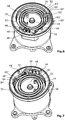
Figur 3 zeigt eine perspektivische Ansicht des Aktors mit einem ersten Ausführungsbeispiel eines Reibminderungselements. -
Figur 4 zeigt eine Draufsicht des erfindungsgemäßen Aktors ausFigur 3 . -
Figur 5 zeigt eine Seitenansicht eines mit den römischen Ziffern V gekennzeichneten Teilausschnitts ausFigur 4 . -
Figur 6 zeigt eine perspektivische Ansicht des Aktors mit einem zweiten Ausführungsbeispiel des Reibminderungselements. -
Figur 7 zeigt eine perspektivische Ansicht des Aktors mit einem dritten Ausführungsbeispiel des Reibminderungselements.
-
Figure 1 shows a side view of an actuator according to the invention with a control body actuated via the actuator including a flow housing in a sectional illustration. -
Figure 2 shows perspective views of the actuator from two different angles with the cover of the actuator open in each case. -
Figure 3 shows a perspective view of the actuator with a first embodiment of a friction reduction element. -
Figure 4 shows a top view of the actuator according to the inventionFigure 3 . -
Figure 5 shows a side view of a partial section marked with the Roman numerals V. FIGFigure 4 . -
Figure 6 shows a perspective view of the actuator with a second exemplary embodiment of the friction reduction element. -
Figure 7 shows a perspective view of the actuator with a third exemplary embodiment of the friction reduction element.
Der in
Der Aktor 10 umfasst einen Elektromotor 11 in einer besonderen Bauform, einen sogenannten Axialflussmotor. Dieser umfasst einen Rotor 12 und einen Stator 14, die axial beabstandet zueinander angeordnet sind, wobei der die Bewegung erzeugende magnetische Fluss zumindest teilweise ebenfalls in axiale Richtung verläuft. Rotierende Komponenten des Aktors 10 und somit zum Rotor 12 zugehörig sind eine Welle 16, ein Rückschlussring 17 sowie ein ringförmiger, mehrpoliger und sektorförmig magnetisierter Rotormagnet 18. Der Rotormagnet 18 ist hierbei an den Rückschlussring 17 angeklebt. Der Rückschlussring 17 wiederum ist an seiner zentralen radialen Bohrung an die Welle 16 geklebt, sodass die Einheit aus Rückschlussring 17 und Rotormagnet 18 stets mit der Welle 16 rotiert. Ein Sensormagnet 19 ist gemäß
Die Welle 16 erstreckt sich axial durch das Aktorgehäuse 24 und tritt über einen Durchbruch im Aktorgehäuse 24 aus dem Aktorgehäuse 24 hinaus und ragt in das Strömungsgehäuse 22 bzw. in einen Strömungskanal 26 hinein. Um den Aktor 10 vor möglichen chemischen und thermischen Auswirkungen von Abgasen zu bewahren, ist im Übergangsbereich zwischen dem Strömungsgehäuse 22 und dem Aktorgehäuse 24 eine die Welle 16 umgebende Dichtung 28 angeordnet, deren Lippengeometrie eine Abdichtung des Strömungsgehäuses 22 gegenüber dem Aktorgehäuse 24 gewährleistet.The
Der Stator 14 umfasst eine bestrombare Wicklung 36 zur Erzeugung eines Magnetfeldes sowie ein Rückschlussblechpaket 38, das im Gehäuse 20 befestigt ist. Über eine Gleitlagerbuchse 40 ist der Stator 14 von der Bewegung der Welle 16 entkoppelt, die in der Gleitlagerbuchse 40 gelagert ist.The
Ein aus Kunststoff gefertigter Deckel 30 des Aktors 10 umfasst einen in
Eine Spiralfeder 50, die aus einem in einer Ebene gewickelten Flachbandmetall gefertigt ist, ist axial zwischen dem Rückschlussring 17 und dem Deckel 30 des Aktors 10 und radial zumindest weitgehend innerhalb des Aktorgehäuses 24 angeordnet. An einem ersten Ende ist die Spiralfeder 50 um etwa 170° gebogen und formschlüssig am Aktorgehäuse 24 befestigt, wie
Der Rückschlussring 17 weist parallel zum Federhaltestift 52 einen Federführungsstift 54 auf, welcher ebenfalls als axialer Vorsprung und mit dem Rückschlussring 17 einteilig ausgebildet ist. Dabei ist der Federführungsstift 54 zum Federhaltestift 52 um etwa 90° in Umfangsrichtung beabstandet. Des Weiteren ist die Spiralfeder 50 in ihrem entspannten Zustand in Radialrichtung beabstandet zum Federführungsstift 54 angeordnet. Der Federführungsstift 54 gewährleistet bei Vorspannung und Spannung der Spiralfeder 50 eine geordnete Bewegung und verbesserte Lagebeständigkeit der Spiralfeder 50, da sie einen Versatz der Spiralfeder 50 nach radial innen einschränkt. Die Spiralfeder 50 wird hierdurch daran gehindert, beliebige Bewegungen auszuführen und wird bei Aktorbetätigungen insgesamt kontrollierter positioniert und geführt.The
Der zwischen die äußeren beiden Segmente der Spiralfeder 50 greifende erste Schenkel 62 stellt sicher, dass die äußeren Segmente der Spiralfeder 50 zu jedem Zeitpunkt zueinander beabstandet bleiben und somit nicht gegeneinander reiben können. Dies reduziert sowohl Eigenreibmomente der Spiralfeder 50, als auch eine damit einhergehende Dissipation. So wird der Energieverbrauch des Aktors 10 zwar geringfügig, aber dennoch gesenkt gegenüber einem Aktor 10 ohne Reibminderungselement 60. Zusätzlich gewährleistet der erste Schenkel 62 bzw. das Reibminderungselement 60, in Analogie zum Federführungsstift 54, eine Führung der Spiralfeder 50 und leistet somit ebenfalls einen Beitrag zur geordneten und kontrollierten Vorspannung und Spannung der Spiralfeder 50.The
Eine alternative Ausgestaltung des Reibminderungselements 60' ist in
Eine dritte Ausführungsform des Reibminderungselements 60" ist in
Bei der Montage des Aktors 10 wird das erste Ende der Spiralfeder 50 am Aktorgehäuse 24 und das zweite Ende am Federhaltestift 52, welcher mit dem Rückschlussring 17 des Rotors 12 einteilig ausgebildet ist, befestigt. Der Rotor 12 und damit auch die in das Strömungsgehäuse 22 hineinragende Welle 16 des Aktors 10, können in diesem Zustand zunächst weitgehend frei drehen, da der tellerförmige Regelkörper 27 zu diesem Zeitpunkt noch nicht mit der Welle 16 des Aktors 10 verbunden ist und der Rotor 12 daher durch keinerlei Anschläge in seiner Bewegung behindert wird. Hierdurch schwingt sich die Spiralfeder 50 gemeinsam mit dem Rotor 12 zunächst in eine Ruhelage der Spiralfeder 50 ein, in der die Spiralfeder 50 unbelastet ist. Ausgehend von dieser Ruhelage wird der Rotor 12 durch manuelle Betätigung der Welle 16 in eine erste Position rotiert und zunächst gehalten. Infolge der Rotation wird die Spiralfeder 50 vorgespannt, d.h. sie ist durch die in dieser ersten Position in ihr gespeicherte Energie bestrebt in ihre Ruhelage zurückzukehren und übt auf den Rotor 12 eine Rückstellkraft aus. In dieser gehaltenen ersten Position ist die Welle 16 beispielsweise dermaßen gedreht, dass ein auf der Welle 16 montierter Regelkörper 27 senkrecht zum Strömungskanal 26 ausgerichtet wäre und diesen daher versperren würde. In der ersten Position der Welle 16 wird der Deckel 30 des Aktors 10 derart positioniert und mit dem Aktorgehäuse 24 form- und kraftschlüssig befestigt, dass der axial aus dem Deckel 30 hervorstehende und axial in den Aktor 10 hineinragende Montageanschlag 42 unmittelbar an dem mit dem Rückschlussring 17 bzw. Rotor 12 einteilig ausgebildeten Federführungsstift 54 anliegt und somit eine Rückrotation des Rotors 12 bzw. der Welle 16 in die Ruhelage der Spiralfeder 50 verhindert. In diesem Fall, d.h. bei geschlossenem Deckel 30, fungiert der Federführungsstift 54 daher zusätzlich als Anschlag für den Montageanschlag 42. Des Weiteren unterstützt der als Bolzen ausgebildete Montageanschlag 42 den Federführungsstift 54 und das Reibminderungselement 60, 60' oder 60" an der Führung der Spiralfeder 50.During the assembly of the
Ausgehend von der ersten Position wird die Welle 16 manuell in eine zweite Position rotiert, in der der Regelkörper 27 an die Welle 16 geschraubt wird, wobei die Drehrichtung von der ersten Position in die zweite Position dieselbe ist wie die Drehrichtung aus der Ruhelage in die erste Position, sodass sich die in der Spiralfeder 50 gespeicherte Energie und damit die Rückstellkraft der Spiralfeder 50 weiter erhöhen. In dieser zweiten Position, in der der Regelkörper 27 an die Welle 16 befestigt ist, kann der Regelkörper 27 an der inneren Wandung des Strömungskanals 26 schräg anliegen und somit den Strömungskanal 26 verschließen. In der zweiten Position, in der der Strömungskanal 26 als Anschlag fungiert, endet der Montagevorgang.Starting from the first position, the
Im Betrieb bewegt sich der Rotor 12 bzw. der Regelkörper 27 zwischen der Position, in der der Regelkörper 27 an der inneren Wandung des Strömungskanals 26 anliegt und einer dritten Position der Welle 16, wobei die Drehrichtung der Welle 16 von der zweiten in die dritte Position dieselbe ist wie die von der ersten in die zweite Position, sodass die die Vorspannung und Rückstellkraft der Spiralfeder 50 in der dritten Position der Welle 16 am größten sind. Die zweite und dritte Position der Welle 16 bilden somit die beiden Endpositionen des Aktors 10. Der Stellweg des Aktors 10 zwischen diesen beiden Endpositionen beträgt hierbei annähernd 70°, wobei die genaue dritte Position durch die Bestromung bzw. Stromstärke des Aktors 10 eingestellt wird. In einer Öffnungsstellung des Ventils, d.h. in Position drei der Welle 16, erstreckt sich die Regelkörperfläche somit in Längsrichtung des Strömungskanals 26 oder mehr oder weniger schräg dazu.In operation, the
Da gewährleistet sein muss, dass im Falle eines Stromausfalls oder einer technischen Störung des Aktors 10 das Ventil in den geschlossenen Zustand, in die sogenannte Fail-Safe-Position, überführt wird, muss die Vorspannung der Spiralfeder 50 hinlänglich groß sein, um den Regelkörper 27 durch die rein mechanisch gespeicherte Energie der Spiralfeder 50 in der dritten Position in die zweite Position der Welle 16 zurückzudrehen und somit das Ventil zu schließen. Hierfür kann die Welle 16 vor der Befestigung des Regelkörpers 27 an die Welle 16 beispielsweise um mindestens 180° von der Ruhelage in die dritte Position gedreht werden.Since it must be ensured that, in the event of a power failure or a technical malfunction of the
Die beschriebenen Figuren dienen ausschließlich der Veranschaulichung ausgewählter Ausführungsbeispiele und stellen nicht die Gesamtheit der möglichen Realisierungen dar und sollen den Umfang der vorliegenden Erfindung nicht einschränken. Es sollte daher deutlich sein, dass der Schutzbereich der vorliegenden Anmeldung nicht auf die beschriebenen Ausführungsbeispiele beschränkt ist. Beispielsweise wäre eine Ausgestaltung denkbar, in der ein oder mehrere Reibminderungselemente in den Deckel integriert sind. Zudem können an Reibminderungselementen Reibreduktionsrollen angeordnet sein. Des Weiteren ist eine Anwendung des Aktors auch in anderen Anwendungsfällen als in Verbrennungskraftmaschinen denkbar.The figures described serve exclusively to illustrate selected exemplary embodiments and do not represent the entirety of the possible implementations and are not intended to restrict the scope of the present invention. It should therefore be clear that the The scope of protection of the present application is not limited to the exemplary embodiments described. For example, an embodiment would be conceivable in which one or more friction-reducing elements are integrated into the cover. In addition, friction reduction rollers can be arranged on friction reduction elements. Furthermore, it is also conceivable to use the actuator in other applications than in internal combustion engines.
Claims (18)
einem Gehäuse (20),
einem im Gehäuse (20) angeordneten Elektromotor (11) mit einem Rotor (12) und einem Stator (14),
einem am Gehäuse (20) befestigbaren Deckel (30),
einer rotierbaren Welle (16), die mit dem Rotor (12) zumindest drehfest verbunden ist, sowie
einer im Gehäuse (20) befestigten und in einer Ebene gewickelten Spiralfeder (50),
dadurch gekennzeichnet, dass
am Gehäuse (20) ein Reibminderungselement (60, 60', 60") für die Spiralfeder (50) angeordnet ist.Actuator (10) for actuating a control body (27) of an internal combustion engine
a housing (20),
an electric motor (11) arranged in the housing (20) with a rotor (12) and a stator (14),
a cover (30) which can be fastened to the housing (20),
a rotatable shaft (16) which is at least non-rotatably connected to the rotor (12), and
a spiral spring (50) fastened in the housing (20) and wound in one plane,
characterized in that
a friction reduction element (60, 60 ', 60 ") for the spiral spring (50) is arranged on the housing (20).
Applications Claiming Priority (1)
| Application Number | Priority Date | Filing Date | Title |
|---|---|---|---|
| DE102019113643.1A DE102019113643B4 (en) | 2019-05-22 | 2019-05-22 | Valve device |
Publications (1)
| Publication Number | Publication Date |
|---|---|
| EP3741986A1 true EP3741986A1 (en) | 2020-11-25 |
Family
ID=70740496
Family Applications (1)
| Application Number | Title | Priority Date | Filing Date |
|---|---|---|---|
| EP20175174.0A Pending EP3741986A1 (en) | 2019-05-22 | 2020-05-18 | Actuator for actuating a control body of an internal combustion engine |
Country Status (2)
| Country | Link |
|---|---|
| EP (1) | EP3741986A1 (en) |
| DE (1) | DE102019113643B4 (en) |
Citations (8)
| Publication number | Priority date | Publication date | Assignee | Title |
|---|---|---|---|---|
| FR1238445A (en) | 1959-07-03 | 1960-08-12 | Lepaute Henry S Ets | Self-starting electric motor with permanent magnets |
| WO1988007625A1 (en) | 1987-03-30 | 1988-10-06 | Robertshaw Controls Company | Exhaust gas recirculation valve construction and method of making |
| US5133320A (en) * | 1990-07-27 | 1992-07-28 | Nippondenso Co., Ltd. | Safety apparatus for combustion engine |
| DE102006051576A1 (en) * | 2006-11-02 | 2008-05-08 | Schaeffler Kg | Belt tensioner for belt drive of internal-combustion engine, has spiral spring with radial inner and outer ends fixed at hub and stopper, where hub is designed as square in cross section, on which inner end is fixed in form fit manner |
| EP2565402A1 (en) * | 2011-09-01 | 2013-03-06 | Schaeffler Technologies AG & Co. KG | Camshaft adjuster |
| DE102013226137A1 (en) * | 2013-12-17 | 2015-06-18 | Schaeffler Technologies AG & Co. KG | Spiral spring winding with partially different winding spacings for local elimination of the winding contact of the individual windings |
| US20160069223A1 (en) * | 2014-09-10 | 2016-03-10 | Hitachi Automotive Systems, Ltd. | Variable valve timing control apparatus of internal combustion engine |
| DE102018108886A1 (en) * | 2017-04-21 | 2018-10-25 | Valeo Systemes De Controle Moteur | Rotary drive device and this comprehensive fluid circulation valve |
Family Cites Families (3)
| Publication number | Priority date | Publication date | Assignee | Title |
|---|---|---|---|---|
| DE102008053570B4 (en) * | 2008-10-15 | 2010-07-08 | Bühler Motor GmbH | Actuator, in particular for actuating an exhaust gas recirculation valve |
| DE102011003769A1 (en) * | 2011-02-08 | 2012-08-09 | Schaeffler Technologies Gmbh & Co. Kg | Camshaft adjuster with a spring |
| DE102013218105A1 (en) * | 2013-09-10 | 2015-03-26 | Schaeffler Technologies AG & Co. KG | Mechanical chain tensioner with spiral spring |
-
2019
- 2019-05-22 DE DE102019113643.1A patent/DE102019113643B4/en active Active
-
2020
- 2020-05-18 EP EP20175174.0A patent/EP3741986A1/en active Pending
Patent Citations (8)
| Publication number | Priority date | Publication date | Assignee | Title |
|---|---|---|---|---|
| FR1238445A (en) | 1959-07-03 | 1960-08-12 | Lepaute Henry S Ets | Self-starting electric motor with permanent magnets |
| WO1988007625A1 (en) | 1987-03-30 | 1988-10-06 | Robertshaw Controls Company | Exhaust gas recirculation valve construction and method of making |
| US5133320A (en) * | 1990-07-27 | 1992-07-28 | Nippondenso Co., Ltd. | Safety apparatus for combustion engine |
| DE102006051576A1 (en) * | 2006-11-02 | 2008-05-08 | Schaeffler Kg | Belt tensioner for belt drive of internal-combustion engine, has spiral spring with radial inner and outer ends fixed at hub and stopper, where hub is designed as square in cross section, on which inner end is fixed in form fit manner |
| EP2565402A1 (en) * | 2011-09-01 | 2013-03-06 | Schaeffler Technologies AG & Co. KG | Camshaft adjuster |
| DE102013226137A1 (en) * | 2013-12-17 | 2015-06-18 | Schaeffler Technologies AG & Co. KG | Spiral spring winding with partially different winding spacings for local elimination of the winding contact of the individual windings |
| US20160069223A1 (en) * | 2014-09-10 | 2016-03-10 | Hitachi Automotive Systems, Ltd. | Variable valve timing control apparatus of internal combustion engine |
| DE102018108886A1 (en) * | 2017-04-21 | 2018-10-25 | Valeo Systemes De Controle Moteur | Rotary drive device and this comprehensive fluid circulation valve |
Also Published As
| Publication number | Publication date |
|---|---|
| DE102019113643B4 (en) | 2021-04-22 |
| DE102019113643A1 (en) | 2020-11-26 |
Similar Documents
| Publication | Publication Date | Title |
|---|---|---|
| EP2756145B1 (en) | Drive device | |
| WO2010086058A1 (en) | Proportional magnet for a hydraulic directional control valve and method for the production thereof | |
| DE202013012708U1 (en) | Electric motor with inner rotor and outer stator | |
| WO2012062495A1 (en) | Camshaft adjuster for an internal combustion engine | |
| EP2390493B1 (en) | Starter motor in a starter for a combustion engine | |
| WO2008071509A1 (en) | Actuator for positioning an actuating member of a variable valve train of an internal combustion engine | |
| EP2033859B1 (en) | Locking device for a shaft of a steering system | |
| DE102006017713A1 (en) | Gear motor for use as e.g. steering servo motor in industrial robot hinge, has drive motor with coils and magnetically influenceable component parts, where locally rotatable deformation of flexible rings is produced by coils and parts | |
| EP2668393B1 (en) | Starting device having an overload safety mechanism | |
| WO2022043266A1 (en) | Electric motor | |
| DE102010003431A1 (en) | Starting device with ring gear and intermediate bearing damping | |
| WO2017008795A1 (en) | Electric motor | |
| DE102019113643B4 (en) | Valve device | |
| DE102015207794A1 (en) | Actuator device and their use | |
| EP3350816B1 (en) | Electromagnetic actuator device and system including thereof | |
| DE102011012020B4 (en) | Camshaft with camshaft adjuster | |
| DE102014208420A1 (en) | Valve actuating device for a valve train of an internal combustion engine | |
| DE60018387T2 (en) | STARTER WITH IMPROVED SUPPORT OF THE LEVER | |
| EP2840274A2 (en) | Free-wheeling and free-wheeling assembly with a free-wheeling mechanism of this type | |
| WO2018103876A1 (en) | Driving unit and drive train device for a motor vehicle | |
| DE102013104642B4 (en) | Electromagnetic actuating device, use of such an electromagnetic actuating device and system having such an electromagnetic actuating device | |
| DE102009012257A1 (en) | Coil-spring mechanism for use as blocking mechanism for blocking undesirable rotary motion of e.g. component in motor vehicle, has friction element provided with running track regions, which are provided with different friction coefficients | |
| DE102007035748A1 (en) | Blocking device for a gear-drive unit in a vehicle comprises a spring element and a braking spring element for stopping an adjusting movement from the blocking position into a releasing position | |
| DE102009028036A1 (en) | Electric motor with permanent magnet excitation | |
| EP3297890B1 (en) | Locking devices |
Legal Events
| Date | Code | Title | Description |
|---|---|---|---|
| PUAI | Public reference made under article 153(3) epc to a published international application that has entered the european phase |
Free format text: ORIGINAL CODE: 0009012 |
|
| STAA | Information on the status of an ep patent application or granted ep patent |
Free format text: STATUS: THE APPLICATION HAS BEEN PUBLISHED |
|
| AK | Designated contracting states |
Kind code of ref document: A1 Designated state(s): AL AT BE BG CH CY CZ DE DK EE ES FI FR GB GR HR HU IE IS IT LI LT LU LV MC MK MT NL NO PL PT RO RS SE SI SK SM TR |
|
| AX | Request for extension of the european patent |
Extension state: BA ME |
|
| STAA | Information on the status of an ep patent application or granted ep patent |
Free format text: STATUS: REQUEST FOR EXAMINATION WAS MADE |
|
| 17P | Request for examination filed |
Effective date: 20210521 |
|
| RBV | Designated contracting states (corrected) |
Designated state(s): AL AT BE BG CH CY CZ DE DK EE ES FI FR GB GR HR HU IE IS IT LI LT LU LV MC MK MT NL NO PL PT RO RS SE SI SK SM TR |
|
| STAA | Information on the status of an ep patent application or granted ep patent |
Free format text: STATUS: EXAMINATION IS IN PROGRESS |
|
| 17Q | First examination report despatched |
Effective date: 20220204 |