EP3741983A1 - High pressure fuel pump and lpdi system with the same - Google Patents
High pressure fuel pump and lpdi system with the same Download PDFInfo
- Publication number
- EP3741983A1 EP3741983A1 EP19207062.1A EP19207062A EP3741983A1 EP 3741983 A1 EP3741983 A1 EP 3741983A1 EP 19207062 A EP19207062 A EP 19207062A EP 3741983 A1 EP3741983 A1 EP 3741983A1
- Authority
- EP
- European Patent Office
- Prior art keywords
- fuel
- high pressure
- fuel pump
- cover
- engine
- Prior art date
- Legal status (The legal status is an assumption and is not a legal conclusion. Google has not performed a legal analysis and makes no representation as to the accuracy of the status listed.)
- Granted
Links
Images





Classifications
-
- F—MECHANICAL ENGINEERING; LIGHTING; HEATING; WEAPONS; BLASTING
- F02—COMBUSTION ENGINES; HOT-GAS OR COMBUSTION-PRODUCT ENGINE PLANTS
- F02M—SUPPLYING COMBUSTION ENGINES IN GENERAL WITH COMBUSTIBLE MIXTURES OR CONSTITUENTS THEREOF
- F02M21/00—Apparatus for supplying engines with non-liquid fuels, e.g. gaseous fuels stored in liquid form
- F02M21/02—Apparatus for supplying engines with non-liquid fuels, e.g. gaseous fuels stored in liquid form for gaseous fuels
- F02M21/0218—Details on the gaseous fuel supply system, e.g. tanks, valves, pipes, pumps, rails, injectors or mixers
- F02M21/0245—High pressure fuel supply systems; Rails; Pumps; Arrangement of valves
-
- F—MECHANICAL ENGINEERING; LIGHTING; HEATING; WEAPONS; BLASTING
- F02—COMBUSTION ENGINES; HOT-GAS OR COMBUSTION-PRODUCT ENGINE PLANTS
- F02M—SUPPLYING COMBUSTION ENGINES IN GENERAL WITH COMBUSTIBLE MIXTURES OR CONSTITUENTS THEREOF
- F02M21/00—Apparatus for supplying engines with non-liquid fuels, e.g. gaseous fuels stored in liquid form
- F02M21/02—Apparatus for supplying engines with non-liquid fuels, e.g. gaseous fuels stored in liquid form for gaseous fuels
- F02M21/0203—Apparatus for supplying engines with non-liquid fuels, e.g. gaseous fuels stored in liquid form for gaseous fuels characterised by the type of gaseous fuel
- F02M21/0209—Hydrocarbon fuels, e.g. methane or acetylene
- F02M21/0212—Hydrocarbon fuels, e.g. methane or acetylene comprising at least 3 C-Atoms, e.g. liquefied petroleum gas [LPG], propane or butane
-
- F—MECHANICAL ENGINEERING; LIGHTING; HEATING; WEAPONS; BLASTING
- F02—COMBUSTION ENGINES; HOT-GAS OR COMBUSTION-PRODUCT ENGINE PLANTS
- F02M—SUPPLYING COMBUSTION ENGINES IN GENERAL WITH COMBUSTIBLE MIXTURES OR CONSTITUENTS THEREOF
- F02M21/00—Apparatus for supplying engines with non-liquid fuels, e.g. gaseous fuels stored in liquid form
- F02M21/02—Apparatus for supplying engines with non-liquid fuels, e.g. gaseous fuels stored in liquid form for gaseous fuels
- F02M21/0218—Details on the gaseous fuel supply system, e.g. tanks, valves, pipes, pumps, rails, injectors or mixers
- F02M21/023—Valves; Pressure or flow regulators in the fuel supply or return system
-
- F—MECHANICAL ENGINEERING; LIGHTING; HEATING; WEAPONS; BLASTING
- F02—COMBUSTION ENGINES; HOT-GAS OR COMBUSTION-PRODUCT ENGINE PLANTS
- F02M—SUPPLYING COMBUSTION ENGINES IN GENERAL WITH COMBUSTIBLE MIXTURES OR CONSTITUENTS THEREOF
- F02M33/00—Other apparatus for treating combustion-air, fuel or fuel-air mixture
- F02M33/02—Other apparatus for treating combustion-air, fuel or fuel-air mixture for collecting and returning condensed fuel
- F02M33/08—Other apparatus for treating combustion-air, fuel or fuel-air mixture for collecting and returning condensed fuel returning to the fuel tank
-
- F—MECHANICAL ENGINEERING; LIGHTING; HEATING; WEAPONS; BLASTING
- F02—COMBUSTION ENGINES; HOT-GAS OR COMBUSTION-PRODUCT ENGINE PLANTS
- F02M—SUPPLYING COMBUSTION ENGINES IN GENERAL WITH COMBUSTIBLE MIXTURES OR CONSTITUENTS THEREOF
- F02M21/00—Apparatus for supplying engines with non-liquid fuels, e.g. gaseous fuels stored in liquid form
- F02M21/02—Apparatus for supplying engines with non-liquid fuels, e.g. gaseous fuels stored in liquid form for gaseous fuels
- F02M21/0218—Details on the gaseous fuel supply system, e.g. tanks, valves, pipes, pumps, rails, injectors or mixers
- F02M21/0221—Fuel storage reservoirs, e.g. cryogenic tanks
-
- F—MECHANICAL ENGINEERING; LIGHTING; HEATING; WEAPONS; BLASTING
- F02—COMBUSTION ENGINES; HOT-GAS OR COMBUSTION-PRODUCT ENGINE PLANTS
- F02M—SUPPLYING COMBUSTION ENGINES IN GENERAL WITH COMBUSTIBLE MIXTURES OR CONSTITUENTS THEREOF
- F02M37/00—Apparatus or systems for feeding liquid fuel from storage containers to carburettors or fuel-injection apparatus; Arrangements for purifying liquid fuel specially adapted for, or arranged on, internal-combustion engines
- F02M37/0011—Constructional details; Manufacturing or assembly of elements of fuel systems; Materials therefor
- F02M37/0041—Means for damping pressure pulsations
-
- F—MECHANICAL ENGINEERING; LIGHTING; HEATING; WEAPONS; BLASTING
- F02—COMBUSTION ENGINES; HOT-GAS OR COMBUSTION-PRODUCT ENGINE PLANTS
- F02M—SUPPLYING COMBUSTION ENGINES IN GENERAL WITH COMBUSTIBLE MIXTURES OR CONSTITUENTS THEREOF
- F02M37/00—Apparatus or systems for feeding liquid fuel from storage containers to carburettors or fuel-injection apparatus; Arrangements for purifying liquid fuel specially adapted for, or arranged on, internal-combustion engines
- F02M37/20—Apparatus or systems for feeding liquid fuel from storage containers to carburettors or fuel-injection apparatus; Arrangements for purifying liquid fuel specially adapted for, or arranged on, internal-combustion engines characterised by means for preventing vapour lock
-
- Y—GENERAL TAGGING OF NEW TECHNOLOGICAL DEVELOPMENTS; GENERAL TAGGING OF CROSS-SECTIONAL TECHNOLOGIES SPANNING OVER SEVERAL SECTIONS OF THE IPC; TECHNICAL SUBJECTS COVERED BY FORMER USPC CROSS-REFERENCE ART COLLECTIONS [XRACs] AND DIGESTS
- Y02—TECHNOLOGIES OR APPLICATIONS FOR MITIGATION OR ADAPTATION AGAINST CLIMATE CHANGE
- Y02T—CLIMATE CHANGE MITIGATION TECHNOLOGIES RELATED TO TRANSPORTATION
- Y02T10/00—Road transport of goods or passengers
- Y02T10/10—Internal combustion engine [ICE] based vehicles
- Y02T10/30—Use of alternative fuels, e.g. biofuels
Definitions
- the present invention relates to a liquid petroleum direct injection (LPDI) system, and more particularly, to a high pressure fuel pump for driving an engine by discharging liquid fuel stored in a bombe at high pressure and injecting the liquid fuel into a cylinder, and an LPDI system including the same.
- LPDI liquid petroleum direct injection
- a liquid petroleum direct injection (LPDI) system installs a high pressure fuel pump on a fuel supply line and drives an engine by injecting liquid fuel, which is discharged at high pressure by the high pressure fuel pump, into a cylinder using an injector.
- LPDI liquid petroleum direct injection
- the LPDI system has the effects of improving power performance of a vehicle, improving fuel efficiency by reducing fuel consumption, and reducing an amount of carbon emission.
- Patent Documents 1 to 3 the applicant of the present invention has disclosed and filed patent applications for an LPDI system and configuration of a high pressure fuel pump applied thereto as shown in Patent Documents 1 to 3 below.
- LPDI system uses LPG fuel
- vaporization and compression of the LPG fuel may occur in the process of using the LPG fuel due to the property of the LPG fuel. This phenomenon is called 'vapor rock'.
- the vapor rock phenomenon is known to occur because liquid and gaseous fuels coexist on a fuel line due to residual heat of an engine compartment when the engine is turned off after driving.
- FIG. 10 is a sectional view of a high pressure fuel pump applied to an LPDI system according to a related art.
- low pressure fuel which is supplied to a fuel recovery line 122 via a low pressure portion 120 provided at an upper portion of a body 110, may cool a piston 130 by passing through a pair of cooling passages 112 connected to upper and lower portions of a high pressure fuel pump 100 through the volume change of the piston 130 generated when the high pressure fuel pump 100 is driven and the piston 130 moves up and down.
- the low pressure fuel introduced through a low pressure fuel inlet 114 is directly introduced into the low pressure portion 120 and then supplied through the fuel recovery line 122.
- the vapor rock phenomenon occurring in the LPDI system of the related art may become a cause of deterioration of startability at the next start after the vehicle has been driven and turned off.
- the vapor rock phenomenon may occur at various positions of a fuel supply system, and the vapor rock phenomenon occurring at the high pressure portion may cause a problem.
- the vapor rock phenomenon occurring in a closed space such as a high pressure fuel pump and a delivery pipe is not easy to solve due to the characteristics of high pressure devices, and thus it is difficult to improve startability.
- liquid and gaseous fuels coexist at an upper end of the high pressure fuel pump.
- a cover is formed in a planar shape by reducing a volume for fuel circulation and pulsation reduction such that the volume is optimized at the time of fuel return, so the vapor inside the cover is not completely eliminated at the time of restarting and fuel circulation, but partially remains inside the cover.
- the high pressure fuel pump according to the related art has a problem in that main components may be worn during driving due to low lubrication caused by the characteristics of the LPG fuel.
- an object of the present invention is to provide a high pressure fuel pump and a liquid petroleum direct injection (LPDI) system including the same, capable of improving startability at the time of restarting by collecting vapor generated due to heat of an engine after driving a vehicle.
- LPDI liquid petroleum direct injection
- Another object of the present invention is to provide a high pressure fuel pump and an LPDI system including the same, capable of preventing components from being worn caused by the characteristics of LPG fuel.
- Still another object of the present invention is to provide a high pressure fuel pump and an LPDI system including the same, capable of cooling a piston at a constant rate by circulating low pressure fuel supplied from a fuel tank to a cooling passage provided inside the high pressure fuel pump at constant pressure and flow rate.
- the present invention provides a high pressure fuel pump including: a body formed at a lateral side thereof with an intake port and an exhaust port, and provided therein with a pressing device configured to press a portion of fuel, which is supplied through the intake port, at a high pressure; a spill valve coupled to one side of the body to control a supply flow rate and exhaust pressure of the fuel; and a cover coupled to an upper portion of the body and having a recovery port for recovering a portion of the fuel supplied into the body to a bombe, wherein the cover collects gaseous fuel vaporized by heat of an engine when the engine is turned off after driving, and has a dome shape which is convex upward to recover the gaseous fuel to the bombe when the engine is restarted.
- a liquid petroleum direct injection system including the high pressure fuel pump includes: a fuel pump configured to pump the fuel stored in the bombe to supply the fuel toward the engine; the high pressure fuel pump configured to receive the fuel supplied from the fuel pump through the intake port formed in the body, press a portion of the fuel at high pressure in a high pressure portion formed inside the body, and transfer the fuel that remains after the fuel is pressurized to a fuel recovery line through the recovery port communicating with the low pressure portion such that the remaining fuel is recovered to the bombe; a delivery pipe connected to the exhaust port of the high pressure fuel pump through which the pressurized fuel is exhausted and filled with the pressurized fuel; an injector configured to directly inject the fuel filled in the delivery pipe into a combustion chamber of an engine; an electronic control unit configured to generate control signals for controlling a motor in the fuel pump, the injector, and a valve of the high pressure fuel pump based on a target rpm of the engine; and a motor controller configured to control a driving of the
- a cover is formed in a convex dome shape so that gaseous fuel can be collected in an inside of the cover, and the collected gaseous fuel can be returned to a bombe at the time of restarting an engine.
- restartability can be improved by collecting gaseous fuel, that is, vaporized fuel generated due to heat of an engine when the engine is turned off after driving, and delivering the vaporized fuel into a bombe upon restarting.
- gaseous fuel that is, vaporized fuel generated due to heat of an engine when the engine is turned off after driving
- a portion of an upper surface of a cover is formed as an inclined surface to collect gaseous fuel, which is vaporized by heat of an engine inside the cover, and the collected gaseous fuel is recovered to a bombe when the engine is restarted so that vapor inside the high pressure fuel pump can be easily eliminated.
- a piston can be cooled always at a constant rate by circulating low pressure fuel, which is supplied from a fuel tank, at constant pressure and flow rate through a cooling passage provided inside a high pressure fuel pump, so the piston can be smoothly operated, thereby ensuring high reliability.
- compatibility can be improved by applying a high pressure fuel pump to an LPDI system.
- FIG. 1 is a block diagram showing the configuration of an LPDI system including the high pressure fuel pump according to an exemplary embodiment of the present invention.
- fuel supplied through a fuel supply line S by the pumping operation of a fuel pump 12 at the start of an engine is initially delivered to a high pressure fuel pump 14 at a constant pressure, for example, a pressure of ⁇ 5 bar, and the fuel pressure supplied at the initial stage of the start is called a 'low pressure'.
- a transfer path for transferring low pressure LPG fuel from an intake port of the high pressure fuel pump 14 to a fuel recovery line R through a recovery port is referred to as a 'low pressure portion 202 (see FIG. 3 )'.
- the LPDI system 10 may include a bombe 11 in which the fuel is stored, the fuel pump 12 installed in the bombe 11 to pump the fuel, the fuel supply line S for supplying the fuel pumped from the fuel pump 12 to an engine E, the high pressure fuel pump 14 for pressurizing the fuel pumped by the fuel pump 12 to a high pressure, a fuel recovery line R for recovering a portion of the fuel supplied to the high pressure fuel pump 14 from the low pressure portion 202 of the high pressure fuel pump 14 to the bombe 11, a delivery pipe 15 in which the fuel pressurized by the high pressure fuel pump 14 is filled at a high pressure, an injector I for directly injecting the fuel, which is filled in the delivery pipe 15 at a high pressure, to a combustion chamber of the engine E, an electronic control unit (17, hereinafter referred to as ECU) for generating control signals to control the driving of a motor inside the fuel pump 12 and the injector I based on the target RPM of the engine E, and
- ECU electronice control unit
- a shut-off valve which is opened or closed according to the driving signal of the motor controller 18 based on the control signal of the ECU 17 to shut off the fuel supplied from the bombe 11, may be installed at a front end of the high pressure fuel pump 14 of the fuel supply line S and a fuel pressure regulator 16, which reduces the pressure of the fuel recovered from the low pressure portion 202 of the high pressure fuel pump 14 to the bombe 11, may be installed at a rear end of the high pressure fuel pump 14 of the fuel recovery line R.
- the fuel pump 12 pumps the LPG fuel stored in the bombe 11 to supply the fuel to the fuel supply line S.
- the fuel supplied through the fuel supply line S is initially delivered to the high pressure fuel pump 14 in a low pressure state, for example, a pressure of about ⁇ 5 bar.
- the high pressure fuel pump 14 may pressurize a portion of the fuel, which is pumped by the fuel pump 12 and supplied through the fuel supply line S at a low pressure, such that a portion of the fuel has a high pressure, for example, about 40 bar to 150 bar. Then, the high pressure fuel pump 14 may supply a portion of the fuel to the delivery pipe 15 and recover the remaining fuel from the low pressure portion 202 to the bombe 11 through the fuel recovery line R.
- first and second pressure sensors may be installed at a front end of the high pressure fuel pump 14 of the fuel supply line S and a rear end of the high pressure fuel pump 14 of the fuel recovery line R, respectively, to detect the pressure of the fuel that is moved, and a third pressure sensor (not shown) may be installed on the delivery pipe 15.
- the ECU 17 may generate the control signals to allow the motor controller 18 to control the driving of the shut-off valve SV, the fuel pump 12, a multi-valve 13 and the fuel pressure regulator 16 according to the fuel pressure detected from the first and second pressure sensors and the third pressure sensor installed on the delivery pipe 15.
- the LPDI system 10 including the high pressure fuel pump according to the exemplary embodiment of the present invention may further include a cut-off valve (not shown).
- the cut-off valve may open or close the fuel recovery line R according to the control signal of the ECU 17.
- the cut-off valve may be configured as a solenoid valve.
- Such a cut-off valve may be operated to close the fuel recovery line R for a predetermined time if an ignition key is operated at the start of the engine. Therefore, the fuel recovered to the bombe 11 may be temporally cut-off by closing the cut-off valve during the start of the engine, so that the pressure of the fuel supplied to the high pressure fuel pump 14 through the fuel supply line S by the pumping operation of the fuel pump 12 can be increased, thereby compressing the vaporized fuel inside the fuel supply line S.
- the high pressure fuel pump 14 may stably receive the fuel, and supply the fuel to the injector I through the delivery pipe 15 by pressurizing all of the supplied fuel to a predetermined high pressure.
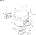
- FIG. 2 is a perspective view showing a high pressure fuel pump according to a first embodiment of the present invention
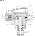
- FIG. 3 is a sectional view taken along line A-A' of FIG. 2
- FIG. 4 is a sectional view taken along line B-B' of FIG. 2 .
- the high pressure fuel pump 14 may include a body 20 formed at a lateral side thereof with an intake port 21 and an exhaust port 22, and provided therein with a pressing device 27 configured to press a portion of fuel, which is supplied through the intake port 21, at a high pressure, a spill valve 26 coupled to one side of the body 20 to control a supply flow rate and exhaust pressure of the fuel, and a cover 24 coupled to an upper portion of the body 20 and having a recovery port 23 for recovering a portion of the fuel supplied into the body to a bombe 11.
- the high pressure fuel pump 14 may further include a roller tappet (not shown) installed between the body 20 and a cam of an engine camshaft (not shown) to convert a rotational motion of the cam into a linear reciprocating motion and transmit the linear reciprocating motion to the pressing device 27.
- a roller tappet (not shown) installed between the body 20 and a cam of an engine camshaft (not shown) to convert a rotational motion of the cam into a linear reciprocating motion and transmit the linear reciprocating motion to the pressing device 27.
- a space in which the pressing device 27 is installed is formed may be formed at a lower portion of the body 20, and the intake port 21 and the exhaust port 22 may be formed at the lateral side of the body 20.
- the fuel introduced into the body 20 through the intake port 21 may be transferred to the low pressure portion 202 provided at an upper portion and an inner portion of the body 20 and the recovery port 23 formed in the cover 24.
- the low pressure portion 202 may serve as a movement passage for the fuel, which is connected to a high pressure portion 201 through the intake port 21, the spill valve 26 and an upper space of the body 20, the inlet 21, the spill valve 26, and the upper space of the body 20, and the high pressure portion 201 may serve as a movement passage for the fuel, which connects an upper portion of the pressing device 27 to the exhaust port 22.
- a bracket 203 may be coupled to an outer peripheral surface of the body 20 to fix the body 20 to a vehicle body.
- the pressing device 27 may generate suction force and pressing force for the fuel in the body 20.
- the pressing device 27 may include a piston 271 connected to the camshaft of the engine via the roller tappet to move up and down and a return spring 272 coupled to the piston 271 to provide a restoring force.
- the pressing device 27 may constitute the high pressure portion 201 together with the body 20.
- the high pressure portion 201 may be a space in which a portion of the fuel is pressurized and may function as a movement passage through which the pressurized fuel moves. That is, the high pressure portion 201 may be formed on a passage through which a portion of the pressurized fuel introduced into the intake port 21 is supplied to the exhaust port 22, and may be formed at an upper portion of the piston 271 of the pressing device 27.
- a micro pipe (not shown) for discharging the vaporized fuel to the low pressure portion 202 may be formed between the high pressure portion 201 defined by the pressing device 27 and the body 20 and the low pressure portion 202 formed inside the body 20.
- the cover 24 may be coupled to the upper portion of the body 20 to shield an upper surface of the body 20, and have a function of collecting the gaseous fuel, which is obtained as liquid-phase fuel is vaporized into gas-phase fuel by the heat of the engine when the engine is turned off after driving.
- the cover 24 may have a dome shape which is convex upward such that a space for collecting the gaseous fuel is provided in the cover 24.
- the upper surface of the cover 24 may be configured as an inclined surface inclined downward to the left in a direction opposite to the recovery port 23 when viewed from FIG. 3 .
- the fuel vaporized by the heat of the engine that is, the gaseous fuel may move to an upper portion of the liquid-phase fuel due to the difference in specific gravity. That is, the gaseous fuel may be collected in the upper portion of the inner space of the cover 24 along the inclined surface in the inner space of the cover 24, and may be recovered to the bombe 11 through the recovery port 23 when the engine is restarted.
- the cover has the dome shape which is convex upward so that the gaseous fuel inside the cover may be collected, and the collected gaseous fuel may be recovered to the bombe when the engine is restarted.
- the vapor existing in the high pressure fuel pump may be collected and recovered to the bombe when the engine is turned off, thereby improving restartability.
- an exhaust-side check valve 28 coupled to the exhaust port 22 and an intake-side check valve 29 connected to the spill valve 26 to supply the fuel introduced into the body 20 to the exhaust-side check valve 28 while preventing the fuel from flowing back may be provided inside the body 20.
- the intake port 21, the exhaust port 22, and the recovery port 23 may be provided with an exhaust opening, an intake opening, and a recovery opening, respectively.
- the spill valve 26 may include a core 31 through which the magnetic flux flows, a sleeve 32 coupled to one side of the core 31, a casing 33 coupled to one side of the sleeve 32, a plunger 34 configured to reciprocate a needle 35 by power applied from an inside of the casing 33, and a spring 36 for providing restoring force to the needle 35.
- a bobbin 37 may be installed at an outer portion of the core 31, a coil 38 may be wound around the bobbin 37, and a housing 39 may be coupled to an outer portion of the bobbin 37.
- a coating layer coated with a coating material may be formed on an outer surface of the plunger 34, which performs the reciprocating motion, to prevent the plunger from being worn due to the characteristics of the LPG fuel having the low lubrication property.
- the present invention can prevent main components, especially the plunger from being worn due to the characteristics of the LPG fuel when the high pressure fuel pump is driven.
- the present invention is not necessarily limited thereto.
- FIG. 5 is a partially enlarged sectional view of the high pressure fuel pump according to a second embodiment of the present invention.
- the high pressure fuel pump 14 according to the second embodiment of the present invention may have a configuration similar to the configuration of the high pressure fuel pump 20 according to the first embodiment described with reference to FIGS. 2 to 4 , except that the recovery port 23 is formed on the upper surface of the cover 24.
- the cover 24 may have a dome shape in which a central portion of the upper surface of the cover 24 formed with the recovery port 23 is convex upward, and the upper surface of the cover 24 may be formed as an inclined surface 241 inclined downward in the outward direction from the center thereof.
- the cover has a dome shape, which is convex upward, to collect gaseous fuel inside the cover and recover the collected gaseous fuel to the bombe when the engine is restarted so that the vapor may be completely removed, thereby improving restartability.
- FIG. 6 is a sectional view of the high pressure fuel pump shown in FIG. 5
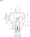
- FIG. 7 is a view showing an operational state of the high pressure fuel pump shown in FIG. 6 .
- the low pressure fuel supplied to the fuel recovery line 122 via the low pressure portion 120 provided at the upper portion of the body 110 may cool the piston 130 by passing through a pair of cooling passages 112 connected to upper and lower portions of the high pressure fuel pump 100 through the volume change of the piston 130 generated when the high pressure fuel pump 100 is driven and the piston 130 moves up and down.
- the conventional high pressure fuel pump 100 changes the flow rate of fuel in association with the change in driving RPM of the high pressure fuel pump 100 in order to cool the piston 130, thereby affecting the cooling rate of the piston 130, which may cause a problem.
- the low pressure fuel supplied from the fuel tank is circulated through the cooling passage provided inside the high pressure fuel pump at a constant pressure and a constant flow rate to cool the piston of the high pressure fuel pump at a constant rate always.
- the high pressure fuel pump 14 may include a blocking wall 40 for blocking an upper end of a cooling passage 205 adjacent to the intake port 21 from the low pressure portion 202.
- the blocking wall 40 may be integrally formed with the body 200 when the high pressure fuel pump 14 is manufactured, or may seal the upper end of the cooling passage 205 by normal welding, pressing or the like to maintain the airtightness of the cooling passage 205 and the low pressure portion 202 such that the blocking wall 40 can be applied to another high pressure fuel pump 14 that has been already manufactured.
- the cooling passage 205 may be sealed by welding or the like after inserting a conventional sealing cap or a conventional sealing rod into the cooling passage 205.
- the blocking wall 40 integrally with the body 20 when the high pressure fuel pump is manufactured.
- the blocking wall 40 formed as described above may block the upper end of the cooling passage 205, the connection structure between the cooling passage 112 and the low pressure portion 120 in the high pressure fuel pump 100 according to the related art is modified and this is one of the technical configurations for circulating the low pressure fuel.
- connection passage 206 may be provided between the intake port 21 and the cooling passage 205 which is blocked from the low pressure portion 202 by the blocking wall 40.
- the low pressure fuel introduced through the intake port 114 is directly supplied to the low pressure portion 120 to cool the piston 130 by passing through the cooling passages 112 connected to the upper and lower portions of the high pressure fuel pump 100 through the volume change of the piston 130 generated when the high pressure fuel pump 100 is driven and the piston 130 moves up and down, so that the cooling efficiency is degraded.
- the low pressure fuel introduced through the blocking wall formed in the cooling passage and the connection passage formed between the cooling passage and the intake port may not be directly supplied to the low pressure portion, but circulated through the cooling passage, so that the high cooling efficiency may be achieved with respect to the heat generated when the piston moves up and down.
- the low pressure fuel flowing into the intake port may be introduced into the low pressure portion and the cooling passage having a closed upper end through the connection passage, and then circulated to the low pressure portion through another cooling passage surrounding the piston, so that the heat exchange may occur by the low pressure fuel having the low temperature, thereby cooling the body provided therein with the piston.
- heat generated from the piston may be cooled so that the piston may be cooled.
- the cooling efficiency of the piston may be further increased by continuously circulating the low temperature fuel to the low pressure portion through the connection passage and the cooling passage.
- the present invention may increase the cooling efficiency of the piston by circulating the low pressure fuel inside the body of the high pressure fuel pump with a simple technical configuration, other than a complicated technical configuration, so that the cooling efficiency for the piston may not be affected even when the flow rate of fuel is changed according to the driving RPM of the high pressure fuel pump, thereby ensuring the high reliability due to the smooth operation of the piston.
- the spill valve 26 may be coupled to the connection passage 206 such that a portion of the low pressure fuel flows into the cooling passage 205 at a constant pressure and a constant flow rate.
- the low pressure fuel flowing into the cooling passage through the connection passage may be constantly introduced when the high pressure fuel pump is driven or operated and even when the low pressure fuel supplied from the fuel tank has an abnormal pressure, so that a constant cooling efficiency may be achieved and the higher reliability may be ensured.
- the present invention may be modified such that the damper portion can be applied to the high pressure fuel pump 14.
- FIG. 8 is a sectional view of a cover and a damper portion of a high pressure fuel pump according to the third embodiment of the present invention
- FIG. 9 is an exploded perspective view of the cover and the damper portion shown in FIG. 8 .
- the high pressure fuel pump 14 may include a damper portion 25 coupled to an upper portion of a body 20 to reduce pulsation of the fuel.
- the cover 24 may be formed in a cylindrical shape with a lower surface opened so that a space for installing the damper portion 25 may be provided in the cover 24, and an edge portion of the cover 24 may be coupled to a plurality of coupling ribs 204 provided at an upper surface of the body 20.
- the damper portion 25 may include a damper 251 having a plurality of valleys formed on an outer surface of the damper portion 25 and an upper guide 252 coupled to an upper portion of the damper 251 to fix the damper 251 to an upper surface of the body.
- a plurality of delivery holes 253 may be formed in the upper guide 252 to deliver the fuel of the low pressure portion 202 to the damper 251.
- Flanges may be provided on outer peripheral surfaces of the damper 251 and the upper guide 252, respectively, and each flange may be press-fitted between the plurality of coupling ribs provided on the upper surface of the edge of the body 20.
- the cover 24 may have a dome shape in which a portion thereof is convex upward so as to collect gaseous fuel vaporized by heat of the engine.
- a portion of the upper surface of the cover 24 may be configured as an inclined surface 241 inclined downward in a direction opposite to the recovery port, and the gaseous fuel may be collected in an upper portion of an inner space of the cover 24 along the inclined surface 241.
- a portion of the upper surface of the cover may be configured as an inclined surface to collect the gaseous fuel, which is vaporized by the heat of the engine, in the cover, and the collected gaseous fuel may be recovered to the bombe when the engine is restarted, so that the vapor inside the high pressure fuel pump may be easily eliminated.
- the present invention may be modified to adopt the blocking wall even when the recovery port is formed on the lateral side of the cover or the damper is provided inside the cover in order to improve the cooling efficiency of the piston.
- the present invention can be applied to the high pressure fuel pump, in which the cover has a dome shape to collect the gaseous fuel vaporized by the heat of the engine and the collected gaseous fuel is recovered to the bombe when the engine is restarted so that the vapor inside the high pressure fuel pump can be easily eliminated, and the LPDI system including the high pressure fuel pump.
Landscapes
- Engineering & Computer Science (AREA)
- Chemical & Material Sciences (AREA)
- Combustion & Propulsion (AREA)
- Mechanical Engineering (AREA)
- General Engineering & Computer Science (AREA)
- Chemical Kinetics & Catalysis (AREA)
- General Chemical & Material Sciences (AREA)
- Oil, Petroleum & Natural Gas (AREA)
- Fuel-Injection Apparatus (AREA)
Abstract
Description
- The present invention relates to a liquid petroleum direct injection (LPDI) system, and more particularly, to a high pressure fuel pump for driving an engine by discharging liquid fuel stored in a bombe at high pressure and injecting the liquid fuel into a cylinder, and an LPDI system including the same.
- In general, unlike a mechanical LPG fuel system that relies on pressure of a fuel tank, a liquid petroleum direct injection (LPDI) system installs a high pressure fuel pump on a fuel supply line and drives an engine by injecting liquid fuel, which is discharged at high pressure by the high pressure fuel pump, into a cylinder using an injector.
- The LPDI system has the effects of improving power performance of a vehicle, improving fuel efficiency by reducing fuel consumption, and reducing an amount of carbon emission.
- For example, the applicant of the present invention has disclosed and filed patent applications for an LPDI system and configuration of a high pressure fuel pump applied thereto as shown in
Patent Documents 1 to 3 below. - Since the LPDI system uses LPG fuel, vaporization and compression of the LPG fuel may occur in the process of using the LPG fuel due to the property of the LPG fuel. This phenomenon is called 'vapor rock'.
- The vapor rock phenomenon is known to occur because liquid and gaseous fuels coexist on a fuel line due to residual heat of an engine compartment when the engine is turned off after driving.
-
FIG. 10 is a sectional view of a high pressure fuel pump applied to an LPDI system according to a related art. - As shown in
FIG. 10 , low pressure fuel, which is supplied to afuel recovery line 122 via alow pressure portion 120 provided at an upper portion of abody 110, may cool apiston 130 by passing through a pair ofcooling passages 112 connected to upper and lower portions of a highpressure fuel pump 100 through the volume change of thepiston 130 generated when the highpressure fuel pump 100 is driven and thepiston 130 moves up and down. In this case, the low pressure fuel introduced through a lowpressure fuel inlet 114 is directly introduced into thelow pressure portion 120 and then supplied through thefuel recovery line 122. - For this reason, there is a problem that an adverse effect may be caused on the cooling rate of the
piston 120 because the flow rate of fuel may vary depending on the drive RPM of the highpressure fuel pump 100. - Meanwhile, the vapor rock phenomenon occurring in the LPDI system of the related art may become a cause of deterioration of startability at the next start after the vehicle has been driven and turned off.
- The vapor rock phenomenon may occur at various positions of a fuel supply system, and the vapor rock phenomenon occurring at the high pressure portion may cause a problem.
- In particular, the vapor rock phenomenon occurring in a closed space such as a high pressure fuel pump and a delivery pipe is not easy to solve due to the characteristics of high pressure devices, and thus it is difficult to improve startability.
- For example, when the vapor rock phenomenon occurs in the high pressure fuel pump applied to the LPDI system of the related art, liquid and gaseous fuels coexist at an upper end of the high pressure fuel pump.
- That is, according to the high pressure fuel pump of the related art, a cover is formed in a planar shape by reducing a volume for fuel circulation and pulsation reduction such that the volume is optimized at the time of fuel return, so the vapor inside the cover is not completely eliminated at the time of restarting and fuel circulation, but partially remains inside the cover.
- In addition, the high pressure fuel pump according to the related art has a problem in that main components may be worn during driving due to low lubrication caused by the characteristics of the LPG fuel.
-
- (Patent Document 1) Korean Patent Registration No.
10-1975824 (issued on April 30, 2019 - (Patent Document 2) Korean Patent Registration No.
10-1987458 (issued on June 3, 2019 - (Patent Document 3) Korean Unexamined Patent Publication No.
10-2014-0106764 (published on September 4, 2014 - In order to solve the problems occurring in the related art, an object of the present invention is to provide a high pressure fuel pump and a liquid petroleum direct injection (LPDI) system including the same, capable of improving startability at the time of restarting by collecting vapor generated due to heat of an engine after driving a vehicle.
- Another object of the present invention is to provide a high pressure fuel pump and an LPDI system including the same, capable of preventing components from being worn caused by the characteristics of LPG fuel.
- Still another object of the present invention is to provide a high pressure fuel pump and an LPDI system including the same, capable of cooling a piston at a constant rate by circulating low pressure fuel supplied from a fuel tank to a cooling passage provided inside the high pressure fuel pump at constant pressure and flow rate.
- In order to achieve the objects as described above, the present invention provides a high pressure fuel pump including: a body formed at a lateral side thereof with an intake port and an exhaust port, and provided therein with a pressing device configured to press a portion of fuel, which is supplied through the intake port, at a high pressure; a spill valve coupled to one side of the body to control a supply flow rate and exhaust pressure of the fuel; and a cover coupled to an upper portion of the body and having a recovery port for recovering a portion of the fuel supplied into the body to a bombe, wherein the cover collects gaseous fuel vaporized by heat of an engine when the engine is turned off after driving, and has a dome shape which is convex upward to recover the gaseous fuel to the bombe when the engine is restarted.
- Further, in order to achieve the objects as described above, a liquid petroleum direct injection system including the high pressure fuel pump according to the present invention includes: a fuel pump configured to pump the fuel stored in the bombe to supply the fuel toward the engine; the high pressure fuel pump configured to receive the fuel supplied from the fuel pump through the intake port formed in the body, press a portion of the fuel at high pressure in a high pressure portion formed inside the body, and transfer the fuel that remains after the fuel is pressurized to a fuel recovery line through the recovery port communicating with the low pressure portion such that the remaining fuel is recovered to the bombe; a delivery pipe connected to the exhaust port of the high pressure fuel pump through which the pressurized fuel is exhausted and filled with the pressurized fuel; an injector configured to directly inject the fuel filled in the delivery pipe into a combustion chamber of an engine; an electronic control unit configured to generate control signals for controlling a motor in the fuel pump, the injector, and a valve of the high pressure fuel pump based on a target rpm of the engine; and a motor controller configured to control a driving of the motor in accordance with the control signal, wherein the cover of the high pressure fuel pump collects gaseous fuel vaporized by heat of the engine when the engine is turned off after driving, and has a dome shape which is convex upward to recover the gaseous fuel to the bombe when the engine is restarted.
- As described above, according to the high pressure fuel pump and the LPDI system including the same of the present invention, a cover is formed in a convex dome shape so that gaseous fuel can be collected in an inside of the cover, and the collected gaseous fuel can be returned to a bombe at the time of restarting an engine.
- Thus, according to the present invention, restartability can be improved by collecting gaseous fuel, that is, vaporized fuel generated due to heat of an engine when the engine is turned off after driving, and delivering the vaporized fuel into a bombe upon restarting.
- In addition, according to the present invention, when a damper portion is provided at an upper portion of a body, a portion of an upper surface of a cover is formed as an inclined surface to collect gaseous fuel, which is vaporized by heat of an engine inside the cover, and the collected gaseous fuel is recovered to a bombe when the engine is restarted so that vapor inside the high pressure fuel pump can be easily eliminated.
- Further, according to the present invention, it is possible to prevent main components from being worn upon driving of a high pressure fuel pump due to low lubrication caused by the characteristics of LPG fuel.
- In addition, according to the present invention, a piston can be cooled always at a constant rate by circulating low pressure fuel, which is supplied from a fuel tank, at constant pressure and flow rate through a cooling passage provided inside a high pressure fuel pump, so the piston can be smoothly operated, thereby ensuring high reliability.
- Further, according to the present invention, compatibility can be improved by applying a high pressure fuel pump to an LPDI system.
-
-
FIG. 1 is a block diagram showing a configuration of an LPDI system including a high pressure fuel pump according to an exemplary embodiment of the present invention. -
FIG. 2 is a perspective view showing a high pressure fuel pump according to a first embodiment of the present invention. -
FIG. 3 is a sectional view taken along line A-A' ofFIG. 2 . -
FIG. 4 is a sectional view taken along line B-B' ofFIG. 2 . -
FIG. 5 is a partially enlarged sectional view of a high pressure fuel pump according to a second embodiment of the present invention. -
FIG. 6 is a sectional view of a high pressure fuel pump shown inFIG. 5 . -
FIG. 7 is a view showing an operation state of a high pressure fuel pump shown inFIG. 5 . -
FIG. 8 is a sectional view showing a cover and a damper portion of a high pressure fuel pump according to a third embodiment of the present invention. -
FIG. 9 is an exploded perspective view of a cover and a damper portion shown inFIG. 8 . -
FIG. 10 is a sectional view of a high pressure fuel pump applied to an LPDI system according to a related art. - Hereinafter, a high pressure fuel pump and a liquid petroleum direct injection (LPDI) system including the same according to an exemplary embodiment of the present invention will be described in detail with reference to the accompanying drawings.
- In the following description, the terms indicating directions such as 'left', 'right', 'front', 'backward', 'upward' and 'downward' are defined as indicating respective directions based on the state shown in the drawings.
- First, the configuration of the LPDI system including the high pressure fuel pump according to the exemplary embodiment of the present invention will be described with reference to
FIG. 1 . -
FIG. 1 is a block diagram showing the configuration of an LPDI system including the high pressure fuel pump according to an exemplary embodiment of the present invention. - In the present embodiment, fuel supplied through a fuel supply line S by the pumping operation of a
fuel pump 12 at the start of an engine is initially delivered to a highpressure fuel pump 14 at a constant pressure, for example, a pressure of Δ5 bar, and the fuel pressure supplied at the initial stage of the start is called a 'low pressure'. - In addition, a transfer path for transferring low pressure LPG fuel from an intake port of the high
pressure fuel pump 14 to a fuel recovery line R through a recovery port is referred to as a 'low pressure portion 202 (seeFIG. 3 )'. - As shown in
FIG. 1 , the LPDIsystem 10 according to the exemplary embodiment of the present invention may include abombe 11 in which the fuel is stored, thefuel pump 12 installed in thebombe 11 to pump the fuel, the fuel supply line S for supplying the fuel pumped from thefuel pump 12 to an engine E, the highpressure fuel pump 14 for pressurizing the fuel pumped by thefuel pump 12 to a high pressure, a fuel recovery line R for recovering a portion of the fuel supplied to the highpressure fuel pump 14 from thelow pressure portion 202 of the highpressure fuel pump 14 to thebombe 11, adelivery pipe 15 in which the fuel pressurized by the highpressure fuel pump 14 is filled at a high pressure, an injector I for directly injecting the fuel, which is filled in thedelivery pipe 15 at a high pressure, to a combustion chamber of the engine E, an electronic control unit (17, hereinafter referred to as ECU) for generating control signals to control the driving of a motor inside thefuel pump 12 and the injector I based on the target RPM of the engine E, and amotor controller 18 for controlling the driving of the motor according to the control signal of theECU 17. - A shut-off valve, which is opened or closed according to the driving signal of the
motor controller 18 based on the control signal of the ECU 17 to shut off the fuel supplied from thebombe 11, may be installed at a front end of the highpressure fuel pump 14 of the fuel supply line S and afuel pressure regulator 16, which reduces the pressure of the fuel recovered from thelow pressure portion 202 of the highpressure fuel pump 14 to thebombe 11, may be installed at a rear end of the highpressure fuel pump 14 of the fuel recovery line R. - The
fuel pump 12 pumps the LPG fuel stored in thebombe 11 to supply the fuel to the fuel supply line S. In this case, the fuel supplied through the fuel supply line S is initially delivered to the highpressure fuel pump 14 in a low pressure state, for example, a pressure of about Δ5 bar. - The high
pressure fuel pump 14 may pressurize a portion of the fuel, which is pumped by thefuel pump 12 and supplied through the fuel supply line S at a low pressure, such that a portion of the fuel has a high pressure, for example, about 40 bar to 150 bar. Then, the highpressure fuel pump 14 may supply a portion of the fuel to thedelivery pipe 15 and recover the remaining fuel from thelow pressure portion 202 to thebombe 11 through the fuel recovery line R. - Meanwhile, first and second pressure sensors (not shown) may be installed at a front end of the high
pressure fuel pump 14 of the fuel supply line S and a rear end of the highpressure fuel pump 14 of the fuel recovery line R, respectively, to detect the pressure of the fuel that is moved, and a third pressure sensor (not shown) may be installed on thedelivery pipe 15. - Thus, the
ECU 17 may generate the control signals to allow themotor controller 18 to control the driving of the shut-off valve SV, thefuel pump 12, a multi-valve 13 and thefuel pressure regulator 16 according to the fuel pressure detected from the first and second pressure sensors and the third pressure sensor installed on thedelivery pipe 15. - In addition, the
LPDI system 10 including the high pressure fuel pump according to the exemplary embodiment of the present invention may further include a cut-off valve (not shown). - The cut-off valve may open or close the fuel recovery line R according to the control signal of the
ECU 17. For example, the cut-off valve may be configured as a solenoid valve. Such a cut-off valve may be operated to close the fuel recovery line R for a predetermined time if an ignition key is operated at the start of the engine. Therefore, the fuel recovered to thebombe 11 may be temporally cut-off by closing the cut-off valve during the start of the engine, so that the pressure of the fuel supplied to the highpressure fuel pump 14 through the fuel supply line S by the pumping operation of thefuel pump 12 can be increased, thereby compressing the vaporized fuel inside the fuel supply line S. - Accordingly, the high
pressure fuel pump 14 may stably receive the fuel, and supply the fuel to the injector I through thedelivery pipe 15 by pressurizing all of the supplied fuel to a predetermined high pressure. - Next, the configuration of the high pressure fuel pump according to a first embodiment of the present invention will be described in detail with reference to
FIGS. 2 to 4 . -
FIG. 2 is a perspective view showing a high pressure fuel pump according to a first embodiment of the present invention,FIG. 3 is a sectional view taken along line A-A' ofFIG. 2 , andFIG. 4 is a sectional view taken along line B-B' ofFIG. 2 . - As shown in
FIGS. 2 to 4 , the highpressure fuel pump 14 according to the first embodiment of the present invention may include abody 20 formed at a lateral side thereof with anintake port 21 and anexhaust port 22, and provided therein with apressing device 27 configured to press a portion of fuel, which is supplied through theintake port 21, at a high pressure, aspill valve 26 coupled to one side of thebody 20 to control a supply flow rate and exhaust pressure of the fuel, and acover 24 coupled to an upper portion of thebody 20 and having arecovery port 23 for recovering a portion of the fuel supplied into the body to abombe 11. - In addition, the high
pressure fuel pump 14 may further include a roller tappet (not shown) installed between thebody 20 and a cam of an engine camshaft (not shown) to convert a rotational motion of the cam into a linear reciprocating motion and transmit the linear reciprocating motion to thepressing device 27. - A space in which the
pressing device 27 is installed is formed may be formed at a lower portion of thebody 20, and theintake port 21 and theexhaust port 22 may be formed at the lateral side of thebody 20. - The fuel introduced into the
body 20 through theintake port 21 may be transferred to thelow pressure portion 202 provided at an upper portion and an inner portion of thebody 20 and therecovery port 23 formed in thecover 24. - That is, the
low pressure portion 202 may serve as a movement passage for the fuel, which is connected to ahigh pressure portion 201 through theintake port 21, thespill valve 26 and an upper space of thebody 20, theinlet 21, thespill valve 26, and the upper space of thebody 20, and thehigh pressure portion 201 may serve as a movement passage for the fuel, which connects an upper portion of thepressing device 27 to theexhaust port 22. - A
bracket 203 may be coupled to an outer peripheral surface of thebody 20 to fix thebody 20 to a vehicle body. - The
pressing device 27 may generate suction force and pressing force for the fuel in thebody 20. - To this end, as shown in
FIG. 3 , thepressing device 27 may include apiston 271 connected to the camshaft of the engine via the roller tappet to move up and down and areturn spring 272 coupled to thepiston 271 to provide a restoring force. - As shown in
FIG. 3 , thepressing device 27 may constitute thehigh pressure portion 201 together with thebody 20. Thehigh pressure portion 201 may be a space in which a portion of the fuel is pressurized and may function as a movement passage through which the pressurized fuel moves. That is, thehigh pressure portion 201 may be formed on a passage through which a portion of the pressurized fuel introduced into theintake port 21 is supplied to theexhaust port 22, and may be formed at an upper portion of thepiston 271 of thepressing device 27. - Meanwhile, when a portion of the fuel is vaporized in an inner space of the
high pressure portion 201, a micro pipe (not shown) for discharging the vaporized fuel to thelow pressure portion 202 may be formed between thehigh pressure portion 201 defined by thepressing device 27 and thebody 20 and thelow pressure portion 202 formed inside thebody 20. - The
cover 24 may be coupled to the upper portion of thebody 20 to shield an upper surface of thebody 20, and have a function of collecting the gaseous fuel, which is obtained as liquid-phase fuel is vaporized into gas-phase fuel by the heat of the engine when the engine is turned off after driving. - To this end, the
cover 24 may have a dome shape which is convex upward such that a space for collecting the gaseous fuel is provided in thecover 24. - In detail, the upper surface of the
cover 24 may be configured as an inclined surface inclined downward to the left in a direction opposite to therecovery port 23 when viewed fromFIG. 3 . - Therefore, the fuel vaporized by the heat of the engine, that is, the gaseous fuel may move to an upper portion of the liquid-phase fuel due to the difference in specific gravity. That is, the gaseous fuel may be collected in the upper portion of the inner space of the
cover 24 along the inclined surface in the inner space of thecover 24, and may be recovered to thebombe 11 through therecovery port 23 when the engine is restarted. - As described above, according to the present invention, the cover has the dome shape which is convex upward so that the gaseous fuel inside the cover may be collected, and the collected gaseous fuel may be recovered to the bombe when the engine is restarted.
- Therefore, according to the present invention, the vapor existing in the high pressure fuel pump may be collected and recovered to the bombe when the engine is turned off, thereby improving restartability.
- Referring again to
FIGS. 2 to 4 , an exhaust-side check valve 28 coupled to theexhaust port 22 and an intake-side check valve 29 connected to thespill valve 26 to supply the fuel introduced into thebody 20 to the exhaust-side check valve 28 while preventing the fuel from flowing back may be provided inside thebody 20. - In addition, the
intake port 21, theexhaust port 22, and therecovery port 23 may be provided with an exhaust opening, an intake opening, and a recovery opening, respectively. - The
spill valve 26 may include a core 31 through which the magnetic flux flows, asleeve 32 coupled to one side of the core 31, acasing 33 coupled to one side of thesleeve 32, aplunger 34 configured to reciprocate aneedle 35 by power applied from an inside of thecasing 33, and aspring 36 for providing restoring force to theneedle 35. - A
bobbin 37 may be installed at an outer portion of the core 31, acoil 38 may be wound around thebobbin 37, and ahousing 39 may be coupled to an outer portion of thebobbin 37. - In the present embodiment, a coating layer coated with a coating material may be formed on an outer surface of the
plunger 34, which performs the reciprocating motion, to prevent the plunger from being worn due to the characteristics of the LPG fuel having the low lubrication property. - Therefore, the present invention can prevent main components, especially the plunger from being worn due to the characteristics of the LPG fuel when the high pressure fuel pump is driven.
- Meanwhile, although the configuration in which the
recovery port 23 is formed at the lateral side of thecover 24 is described in the present embodiment, the present invention is not necessarily limited thereto. -
FIG. 5 is a partially enlarged sectional view of the high pressure fuel pump according to a second embodiment of the present invention. - As shown in
FIG. 5 , the highpressure fuel pump 14 according to the second embodiment of the present invention may have a configuration similar to the configuration of the highpressure fuel pump 20 according to the first embodiment described with reference toFIGS. 2 to 4 , except that therecovery port 23 is formed on the upper surface of thecover 24. - Therefore, the
cover 24 may have a dome shape in which a central portion of the upper surface of thecover 24 formed with therecovery port 23 is convex upward, and the upper surface of thecover 24 may be formed as aninclined surface 241 inclined downward in the outward direction from the center thereof. - As described above, according to the present invention, the cover has a dome shape, which is convex upward, to collect gaseous fuel inside the cover and recover the collected gaseous fuel to the bombe when the engine is restarted so that the vapor may be completely removed, thereby improving restartability.
- Meanwhile,
FIG. 6 is a sectional view of the high pressure fuel pump shown inFIG. 5 , andFIG. 7 is a view showing an operational state of the high pressure fuel pump shown inFIG. 6 . - As described above reference to
FIG. 10 , in the conventional highpressure fuel pump 100, the low pressure fuel supplied to thefuel recovery line 122 via thelow pressure portion 120 provided at the upper portion of thebody 110 may cool thepiston 130 by passing through a pair ofcooling passages 112 connected to upper and lower portions of the highpressure fuel pump 100 through the volume change of thepiston 130 generated when the highpressure fuel pump 100 is driven and thepiston 130 moves up and down. - However, the conventional high
pressure fuel pump 100 changes the flow rate of fuel in association with the change in driving RPM of the highpressure fuel pump 100 in order to cool thepiston 130, thereby affecting the cooling rate of thepiston 130, which may cause a problem. - In order to solve the above problem, according to the present invention, the low pressure fuel supplied from the fuel tank is circulated through the cooling passage provided inside the high pressure fuel pump at a constant pressure and a constant flow rate to cool the piston of the high pressure fuel pump at a constant rate always.
- In detail, as shown in
FIGS. 6 and7 , the highpressure fuel pump 14 according to the present invention may include a blockingwall 40 for blocking an upper end of acooling passage 205 adjacent to theintake port 21 from thelow pressure portion 202. - The blocking
wall 40 may be integrally formed with the body 200 when the highpressure fuel pump 14 is manufactured, or may seal the upper end of thecooling passage 205 by normal welding, pressing or the like to maintain the airtightness of thecooling passage 205 and thelow pressure portion 202 such that the blockingwall 40 can be applied to another highpressure fuel pump 14 that has been already manufactured. - Alternatively, the
cooling passage 205 may be sealed by welding or the like after inserting a conventional sealing cap or a conventional sealing rod into thecooling passage 205. - However, in order to improve workability, it is desirable to form the blocking
wall 40 integrally with thebody 20 when the high pressure fuel pump is manufactured. - As the blocking
wall 40 formed as described above may block the upper end of thecooling passage 205, the connection structure between thecooling passage 112 and thelow pressure portion 120 in the highpressure fuel pump 100 according to the related art is modified and this is one of the technical configurations for circulating the low pressure fuel. - In addition, a
connection passage 206 may be provided between theintake port 21 and thecooling passage 205 which is blocked from thelow pressure portion 202 by the blockingwall 40. - In other words, according to the configuration of the related art as shown in
FIG. 10 , the low pressure fuel introduced through theintake port 114 is directly supplied to thelow pressure portion 120 to cool thepiston 130 by passing through thecooling passages 112 connected to the upper and lower portions of the highpressure fuel pump 100 through the volume change of thepiston 130 generated when the highpressure fuel pump 100 is driven and thepiston 130 moves up and down, so that the cooling efficiency is degraded. - In contrast, according to the present invention, the low pressure fuel introduced through the blocking wall formed in the cooling passage and the connection passage formed between the cooling passage and the intake port may not be directly supplied to the low pressure portion, but circulated through the cooling passage, so that the high cooling efficiency may be achieved with respect to the heat generated when the piston moves up and down.
- That is, according to the present invention, the low pressure fuel flowing into the intake port may be introduced into the low pressure portion and the cooling passage having a closed upper end through the connection passage, and then circulated to the low pressure portion through another cooling passage surrounding the piston, so that the heat exchange may occur by the low pressure fuel having the low temperature, thereby cooling the body provided therein with the piston. As a result, heat generated from the piston may be cooled so that the piston may be cooled.
- In particular, according to the present invention, the cooling efficiency of the piston may be further increased by continuously circulating the low temperature fuel to the low pressure portion through the connection passage and the cooling passage.
- In this manner, the present invention may increase the cooling efficiency of the piston by circulating the low pressure fuel inside the body of the high pressure fuel pump with a simple technical configuration, other than a complicated technical configuration, so that the cooling efficiency for the piston may not be affected even when the flow rate of fuel is changed according to the driving RPM of the high pressure fuel pump, thereby ensuring the high reliability due to the smooth operation of the piston.
- Meanwhile, the
spill valve 26 may be coupled to theconnection passage 206 such that a portion of the low pressure fuel flows into thecooling passage 205 at a constant pressure and a constant flow rate. - In other words, the low pressure fuel flowing into the cooling passage through the connection passage may be constantly introduced when the high pressure fuel pump is driven or operated and even when the low pressure fuel supplied from the fuel tank has an abnormal pressure, so that a constant cooling efficiency may be achieved and the higher reliability may be ensured.
- Meanwhile, although the first and second embodiments have been described with the configuration in which a damper portion for reducing pulsation of the fuel is omitted, the present invention may be modified such that the damper portion can be applied to the high
pressure fuel pump 14. -
FIG. 8 is a sectional view of a cover and a damper portion of a high pressure fuel pump according to the third embodiment of the present invention, andFIG. 9 is an exploded perspective view of the cover and the damper portion shown inFIG. 8 . - As shown in
FIGS. 8 and9 , the highpressure fuel pump 14 according to the third embodiment of the present invention may include adamper portion 25 coupled to an upper portion of abody 20 to reduce pulsation of the fuel. - The
cover 24 may be formed in a cylindrical shape with a lower surface opened so that a space for installing thedamper portion 25 may be provided in thecover 24, and an edge portion of thecover 24 may be coupled to a plurality ofcoupling ribs 204 provided at an upper surface of thebody 20. - The
damper portion 25 may include adamper 251 having a plurality of valleys formed on an outer surface of thedamper portion 25 and anupper guide 252 coupled to an upper portion of thedamper 251 to fix thedamper 251 to an upper surface of the body. - A plurality of
delivery holes 253 may be formed in theupper guide 252 to deliver the fuel of thelow pressure portion 202 to thedamper 251. - Flanges may be provided on outer peripheral surfaces of the
damper 251 and theupper guide 252, respectively, and each flange may be press-fitted between the plurality of coupling ribs provided on the upper surface of the edge of thebody 20. - Meanwhile, the
cover 24 may have a dome shape in which a portion thereof is convex upward so as to collect gaseous fuel vaporized by heat of the engine. - That is, a portion of the upper surface of the
cover 24 may be configured as aninclined surface 241 inclined downward in a direction opposite to the recovery port, and the gaseous fuel may be collected in an upper portion of an inner space of thecover 24 along theinclined surface 241. - As described above, when the damper portion is provided on the upper portion of the body, a portion of the upper surface of the cover may be configured as an inclined surface to collect the gaseous fuel, which is vaporized by the heat of the engine, in the cover, and the collected gaseous fuel may be recovered to the bombe when the engine is restarted, so that the vapor inside the high pressure fuel pump may be easily eliminated.
- As mentioned above, although the invention made by the inventor(s) of the present invention has been specifically described, the present invention is not limited to the above embodiments and variously changes may be made without departing from the sprint of the present invention.
- That is, although the configuration of the blocking wall has been described in the second embodiment in which the recovery port is formed on the upper surface of the cover, the present invention is not necessarily limited thereto.
- For example, the present invention may be modified to adopt the blocking wall even when the recovery port is formed on the lateral side of the cover or the damper is provided inside the cover in order to improve the cooling efficiency of the piston.
- The present invention can be applied to the high pressure fuel pump, in which the cover has a dome shape to collect the gaseous fuel vaporized by the heat of the engine and the collected gaseous fuel is recovered to the bombe when the engine is restarted so that the vapor inside the high pressure fuel pump can be easily eliminated, and the LPDI system including the high pressure fuel pump.
Claims (9)
- A high pressure fuel pump comprising:a body formed at a lateral side thereof with an intake port and an exhaust port, and provided therein with a pressing device configured to press a portion of fuel, which is supplied through the intake port, at a high pressure;a spill valve coupled to one side of the body to control a supply flow rate and exhaust pressure of the fuel; anda cover coupled to an upper portion of the body and having a recovery port for recovering a portion of the fuel supplied into the body to a bombe,wherein the cover collects gaseous fuel vaporized by heat of an engine when the engine is turned off after driving, and has a dome shape which is convex upward to recover the gaseous fuel to the bombe when the engine is restarted.
- The high pressure fuel pump of claim 1, wherein an upper surface of the cover is configured as an inclined surface inclined to one side, and the gaseous fuel in an inner space of the cover is moved along the inclined surface and collected in an upper portion of the inner space of the cover.
- The high pressure fuel pump of claim 2, wherein the upper surface of the cover is configured as an inclined surface inclined downward in a direction opposite to the recovery port when the recovery port is formed at a lateral side of the cover.
- The high pressure fuel pump of claim 2, wherein the upper surface of the cover is configured as an inclined surface inclined downward in an outward direction from the recovery port when the recovery port is formed at the upper surface of the cover.
- The high pressure fuel pump of one of claims 1 to 4, further comprising a damper portion provided at an upper portion of the body to reduce pulsation of the fuel,
Wherein the cover has a cylindrical shape with a lower surface opened to provide a space in which the damper portion is installed, and
an inclined surface inclined downward in a direction opposite to the recovery port formed at the lateral side of the cover is formed on a portion of the upper surface of the cover. - The high pressure fuel pump of one of claims 1 to 5, wherein a pair of cooling passages are formed in the body, in which the fuel introduced through the intake port is moved to a low pressure portion formed inside the cover through the cooling passages before the fuel is pressurized at high pressure to cool a piston,
a blocking wall is formed at an upper end of one of the pair of cooling passages adjacent to the intake port to block the fuel introduced through the intake port such that the fuel is not transferred to the low pressure portion, and
a connection passage is formed between the intake port and the cooling passage in which the blocking wall is formed. - The high pressure fuel pump of claim 6, wherein the blocking wall is formed integrally with the body, or configured to seal an upper end of the cooling passage such that the cooling passage and the low pressure portion have airtightness.
- The high pressure fuel pump of one of claims 1 to 7, wherein the spill valve includes:a core through which a magnetic flux flows;a sleeve coupled to one side of the core;a casing coupled to one side of the sleeve;a plunger configured to reciprocate a needle by power applied from an inside of the casing;a spring configured to apply restoring force to the needle; anda bobbin installed outside the core, in which a coil is wound on an outer peripheral surface of the bobbin,wherein an outer surface of the plunger is coated with a coating material to prevent the plunger from being worn during a reciprocating motion.
- A liquid petroleum direct injection system including the high pressure fuel pump according to one of claims 1 to 8, the liquid petroleum direct injection system comprising:a fuel pump configured to pump the fuel stored in the bombe to supply the fuel toward the engine;the high pressure fuel pump configured to receive the fuel supplied from the fuel pump through the intake port formed in the body, press a portion of the fuel at high pressure in a high pressure portion formed inside the body, and transfer the fuel that remains after the fuel is pressurized to a fuel recovery line through the recovery port communicating with the low pressure portion such that the remaining fuel is recovered to the bombe;a delivery pipe connected to the exhaust port of the high pressure fuel pump through which the pressurized fuel is exhausted and filled with the pressurized fuel;an injector configured to directly inject the fuel filled in the delivery pipe into a combustion chamber of an engine;an electronic control unit configured to generate control signals for controlling a motor in the fuel pump, the injector, and a valve of the high pressure fuel pump based on a target rpm of the engine; anda motor controller configured to control a driving of the motor in accordance with the control signal,wherein the cover of the high pressure fuel pump collects gaseous fuel vaporized by heat of the engine when the engine is turned off after driving, and has a dome shape which is convex upward to recover the gaseous fuel to the bombe when the engine is restarted.
Applications Claiming Priority (2)
| Application Number | Priority Date | Filing Date | Title |
|---|---|---|---|
| KR1020190060284A KR20200134616A (en) | 2019-05-22 | 2019-05-22 | Piston cooling device of LPDI high-pressure fuel pump |
| KR1020190114135A KR102228818B1 (en) | 2019-09-17 | 2019-09-17 | High pressure fuel pump and lpdi system with the same |
Publications (2)
| Publication Number | Publication Date |
|---|---|
| EP3741983A1 true EP3741983A1 (en) | 2020-11-25 |
| EP3741983B1 EP3741983B1 (en) | 2023-05-03 |
Family
ID=68468587
Family Applications (1)
| Application Number | Title | Priority Date | Filing Date |
|---|---|---|---|
| EP19207062.1A Active EP3741983B1 (en) | 2019-05-22 | 2019-11-05 | High pressure fuel pump |
Country Status (1)
| Country | Link |
|---|---|
| EP (1) | EP3741983B1 (en) |
Citations (7)
| Publication number | Priority date | Publication date | Assignee | Title |
|---|---|---|---|---|
| KR20120064817A (en) * | 2010-12-10 | 2012-06-20 | (주)모토닉 | Direct injection type liquefied petroleum-gas injection system |
| KR101182130B1 (en) * | 2010-08-23 | 2012-09-12 | (주)모토닉 | High presure fuel pump for direct injection type gasoline engine |
| KR20140106764A (en) | 2013-02-19 | 2014-09-04 | (주)모토닉 | High presure fuel pump for direct injection type liquid petroleum injection system |
| KR20170048279A (en) * | 2017-04-20 | 2017-05-08 | (주)모토닉 | Liquid petroleum-gas direct injection system |
| DE102017210630A1 (en) * | 2016-07-05 | 2018-01-11 | Hyundai Motor Company | A fuel supply device for a direct injection gasoline engine and start-up control method for a direct injection gasoline engine with the fuel supply device |
| KR101975824B1 (en) | 2017-11-28 | 2019-05-08 | (주)모토닉 | Liquid petroleum-gas direct injection system |
| KR101987458B1 (en) | 2018-03-21 | 2019-06-12 | (주)모토닉 | High pressure fuel pump and lpdi system |
-
2019
- 2019-11-05 EP EP19207062.1A patent/EP3741983B1/en active Active
Patent Citations (7)
| Publication number | Priority date | Publication date | Assignee | Title |
|---|---|---|---|---|
| KR101182130B1 (en) * | 2010-08-23 | 2012-09-12 | (주)모토닉 | High presure fuel pump for direct injection type gasoline engine |
| KR20120064817A (en) * | 2010-12-10 | 2012-06-20 | (주)모토닉 | Direct injection type liquefied petroleum-gas injection system |
| KR20140106764A (en) | 2013-02-19 | 2014-09-04 | (주)모토닉 | High presure fuel pump for direct injection type liquid petroleum injection system |
| DE102017210630A1 (en) * | 2016-07-05 | 2018-01-11 | Hyundai Motor Company | A fuel supply device for a direct injection gasoline engine and start-up control method for a direct injection gasoline engine with the fuel supply device |
| KR20170048279A (en) * | 2017-04-20 | 2017-05-08 | (주)모토닉 | Liquid petroleum-gas direct injection system |
| KR101975824B1 (en) | 2017-11-28 | 2019-05-08 | (주)모토닉 | Liquid petroleum-gas direct injection system |
| KR101987458B1 (en) | 2018-03-21 | 2019-06-12 | (주)모토닉 | High pressure fuel pump and lpdi system |
Also Published As
| Publication number | Publication date |
|---|---|
| EP3741983B1 (en) | 2023-05-03 |
Similar Documents
| Publication | Publication Date | Title |
|---|---|---|
| CN102753813B (en) | High-pressure fuel feed pump | |
| US8882475B2 (en) | Electromagnetic flow rate control valve and high-pressure fuel supply pump using the same | |
| JP2003003925A (en) | Fuel supply system for alternative fuels | |
| EP3587790B1 (en) | High-pressure fuel supply pump | |
| JP6135437B2 (en) | High pressure fuel pump | |
| KR20170011832A (en) | Liquid petroleum-gas direct injection system | |
| JP2006291838A (en) | High pressure fuel pump | |
| JP5321432B2 (en) | Fuel supply device | |
| JP5673284B2 (en) | High pressure pump | |
| US11149655B2 (en) | High pressure fuel pump and LPDI system with the same | |
| EP3741983B1 (en) | High pressure fuel pump | |
| KR101465632B1 (en) | High presure fuel pump for direct injection type liquid petroleum injection system | |
| JP2003262167A (en) | Dme fuel feed device of diesel engine | |
| US8608456B2 (en) | High pressure pump | |
| KR101987458B1 (en) | High pressure fuel pump and lpdi system | |
| JP2001221118A (en) | Fuel injection device | |
| JP2002364491A (en) | High pressure pump for alternative fuels | |
| JP5703893B2 (en) | High pressure pump | |
| JP2009103008A (en) | Fuel pump | |
| WO2004092572A1 (en) | Fuel feed device | |
| CN112005003B (en) | Fuel delivery device for cryogenic fuels | |
| JP4552834B2 (en) | Fuel injection device | |
| KR20140106764A (en) | High presure fuel pump for direct injection type liquid petroleum injection system | |
| KR101819897B1 (en) | Liquid petroleum-gas direct injection system | |
| JP7644684B2 (en) | Fuel Pump |
Legal Events
| Date | Code | Title | Description |
|---|---|---|---|
| PUAI | Public reference made under article 153(3) epc to a published international application that has entered the european phase |
Free format text: ORIGINAL CODE: 0009012 |
|
| STAA | Information on the status of an ep patent application or granted ep patent |
Free format text: STATUS: REQUEST FOR EXAMINATION WAS MADE |
|
| 17P | Request for examination filed |
Effective date: 20191105 |
|
| AK | Designated contracting states |
Kind code of ref document: A1 Designated state(s): AL AT BE BG CH CY CZ DE DK EE ES FI FR GB GR HR HU IE IS IT LI LT LU LV MC MK MT NL NO PL PT RO RS SE SI SK SM TR |
|
| AX | Request for extension of the european patent |
Extension state: BA ME |
|
| STAA | Information on the status of an ep patent application or granted ep patent |
Free format text: STATUS: EXAMINATION IS IN PROGRESS |
|
| 17Q | First examination report despatched |
Effective date: 20210824 |
|
| GRAP | Despatch of communication of intention to grant a patent |
Free format text: ORIGINAL CODE: EPIDOSNIGR1 |
|
| STAA | Information on the status of an ep patent application or granted ep patent |
Free format text: STATUS: GRANT OF PATENT IS INTENDED |
|
| INTG | Intention to grant announced |
Effective date: 20221202 |
|
| GRAS | Grant fee paid |
Free format text: ORIGINAL CODE: EPIDOSNIGR3 |
|
| GRAA | (expected) grant |
Free format text: ORIGINAL CODE: 0009210 |
|
| STAA | Information on the status of an ep patent application or granted ep patent |
Free format text: STATUS: THE PATENT HAS BEEN GRANTED |
|
| AK | Designated contracting states |
Kind code of ref document: B1 Designated state(s): AL AT BE BG CH CY CZ DE DK EE ES FI FR GB GR HR HU IE IS IT LI LT LU LV MC MK MT NL NO PL PT RO RS SE SI SK SM TR |
|
| REG | Reference to a national code |
Ref country code: GB Ref legal event code: FG4D |
|
| REG | Reference to a national code |
Ref country code: AT Ref legal event code: REF Ref document number: 1564793 Country of ref document: AT Kind code of ref document: T Effective date: 20230515 Ref country code: CH Ref legal event code: EP |
|
| REG | Reference to a national code |
Ref country code: DE Ref legal event code: R096 Ref document number: 602019028308 Country of ref document: DE |
|
| REG | Reference to a national code |
Ref country code: IE Ref legal event code: FG4D |
|
| REG | Reference to a national code |
Ref country code: LT Ref legal event code: MG9D |
|
| REG | Reference to a national code |
Ref country code: NL Ref legal event code: MP Effective date: 20230503 |
|
| REG | Reference to a national code |
Ref country code: AT Ref legal event code: MK05 Ref document number: 1564793 Country of ref document: AT Kind code of ref document: T Effective date: 20230503 |
|
| PG25 | Lapsed in a contracting state [announced via postgrant information from national office to epo] |
Ref country code: SE Free format text: LAPSE BECAUSE OF FAILURE TO SUBMIT A TRANSLATION OF THE DESCRIPTION OR TO PAY THE FEE WITHIN THE PRESCRIBED TIME-LIMIT Effective date: 20230503 Ref country code: PT Free format text: LAPSE BECAUSE OF FAILURE TO SUBMIT A TRANSLATION OF THE DESCRIPTION OR TO PAY THE FEE WITHIN THE PRESCRIBED TIME-LIMIT Effective date: 20230904 Ref country code: NO Free format text: LAPSE BECAUSE OF FAILURE TO SUBMIT A TRANSLATION OF THE DESCRIPTION OR TO PAY THE FEE WITHIN THE PRESCRIBED TIME-LIMIT Effective date: 20230803 Ref country code: NL Free format text: LAPSE BECAUSE OF FAILURE TO SUBMIT A TRANSLATION OF THE DESCRIPTION OR TO PAY THE FEE WITHIN THE PRESCRIBED TIME-LIMIT Effective date: 20230503 Ref country code: ES Free format text: LAPSE BECAUSE OF FAILURE TO SUBMIT A TRANSLATION OF THE DESCRIPTION OR TO PAY THE FEE WITHIN THE PRESCRIBED TIME-LIMIT Effective date: 20230503 Ref country code: AT Free format text: LAPSE BECAUSE OF FAILURE TO SUBMIT A TRANSLATION OF THE DESCRIPTION OR TO PAY THE FEE WITHIN THE PRESCRIBED TIME-LIMIT Effective date: 20230503 |
|
| PG25 | Lapsed in a contracting state [announced via postgrant information from national office to epo] |
Ref country code: RS Free format text: LAPSE BECAUSE OF FAILURE TO SUBMIT A TRANSLATION OF THE DESCRIPTION OR TO PAY THE FEE WITHIN THE PRESCRIBED TIME-LIMIT Effective date: 20230503 Ref country code: PL Free format text: LAPSE BECAUSE OF FAILURE TO SUBMIT A TRANSLATION OF THE DESCRIPTION OR TO PAY THE FEE WITHIN THE PRESCRIBED TIME-LIMIT Effective date: 20230503 Ref country code: LV Free format text: LAPSE BECAUSE OF FAILURE TO SUBMIT A TRANSLATION OF THE DESCRIPTION OR TO PAY THE FEE WITHIN THE PRESCRIBED TIME-LIMIT Effective date: 20230503 Ref country code: LT Free format text: LAPSE BECAUSE OF FAILURE TO SUBMIT A TRANSLATION OF THE DESCRIPTION OR TO PAY THE FEE WITHIN THE PRESCRIBED TIME-LIMIT Effective date: 20230503 Ref country code: IS Free format text: LAPSE BECAUSE OF FAILURE TO SUBMIT A TRANSLATION OF THE DESCRIPTION OR TO PAY THE FEE WITHIN THE PRESCRIBED TIME-LIMIT Effective date: 20230903 Ref country code: HR Free format text: LAPSE BECAUSE OF FAILURE TO SUBMIT A TRANSLATION OF THE DESCRIPTION OR TO PAY THE FEE WITHIN THE PRESCRIBED TIME-LIMIT Effective date: 20230503 Ref country code: GR Free format text: LAPSE BECAUSE OF FAILURE TO SUBMIT A TRANSLATION OF THE DESCRIPTION OR TO PAY THE FEE WITHIN THE PRESCRIBED TIME-LIMIT Effective date: 20230804 |
|
| PG25 | Lapsed in a contracting state [announced via postgrant information from national office to epo] |
Ref country code: FI Free format text: LAPSE BECAUSE OF FAILURE TO SUBMIT A TRANSLATION OF THE DESCRIPTION OR TO PAY THE FEE WITHIN THE PRESCRIBED TIME-LIMIT Effective date: 20230503 |
|
| PG25 | Lapsed in a contracting state [announced via postgrant information from national office to epo] |
Ref country code: SK Free format text: LAPSE BECAUSE OF FAILURE TO SUBMIT A TRANSLATION OF THE DESCRIPTION OR TO PAY THE FEE WITHIN THE PRESCRIBED TIME-LIMIT Effective date: 20230503 |
|
| PG25 | Lapsed in a contracting state [announced via postgrant information from national office to epo] |
Ref country code: SM Free format text: LAPSE BECAUSE OF FAILURE TO SUBMIT A TRANSLATION OF THE DESCRIPTION OR TO PAY THE FEE WITHIN THE PRESCRIBED TIME-LIMIT Effective date: 20230503 Ref country code: SK Free format text: LAPSE BECAUSE OF FAILURE TO SUBMIT A TRANSLATION OF THE DESCRIPTION OR TO PAY THE FEE WITHIN THE PRESCRIBED TIME-LIMIT Effective date: 20230503 Ref country code: RO Free format text: LAPSE BECAUSE OF FAILURE TO SUBMIT A TRANSLATION OF THE DESCRIPTION OR TO PAY THE FEE WITHIN THE PRESCRIBED TIME-LIMIT Effective date: 20230503 Ref country code: EE Free format text: LAPSE BECAUSE OF FAILURE TO SUBMIT A TRANSLATION OF THE DESCRIPTION OR TO PAY THE FEE WITHIN THE PRESCRIBED TIME-LIMIT Effective date: 20230503 Ref country code: DK Free format text: LAPSE BECAUSE OF FAILURE TO SUBMIT A TRANSLATION OF THE DESCRIPTION OR TO PAY THE FEE WITHIN THE PRESCRIBED TIME-LIMIT Effective date: 20230503 Ref country code: CZ Free format text: LAPSE BECAUSE OF FAILURE TO SUBMIT A TRANSLATION OF THE DESCRIPTION OR TO PAY THE FEE WITHIN THE PRESCRIBED TIME-LIMIT Effective date: 20230503 |
|
| REG | Reference to a national code |
Ref country code: DE Ref legal event code: R097 Ref document number: 602019028308 Country of ref document: DE |
|
| PLBE | No opposition filed within time limit |
Free format text: ORIGINAL CODE: 0009261 |
|
| STAA | Information on the status of an ep patent application or granted ep patent |
Free format text: STATUS: NO OPPOSITION FILED WITHIN TIME LIMIT |
|
| 26N | No opposition filed |
Effective date: 20240206 |
|
| PG25 | Lapsed in a contracting state [announced via postgrant information from national office to epo] |
Ref country code: SI Free format text: LAPSE BECAUSE OF FAILURE TO SUBMIT A TRANSLATION OF THE DESCRIPTION OR TO PAY THE FEE WITHIN THE PRESCRIBED TIME-LIMIT Effective date: 20230503 |
|
| PG25 | Lapsed in a contracting state [announced via postgrant information from national office to epo] |
Ref country code: SI Free format text: LAPSE BECAUSE OF FAILURE TO SUBMIT A TRANSLATION OF THE DESCRIPTION OR TO PAY THE FEE WITHIN THE PRESCRIBED TIME-LIMIT Effective date: 20230503 Ref country code: IT Free format text: LAPSE BECAUSE OF FAILURE TO SUBMIT A TRANSLATION OF THE DESCRIPTION OR TO PAY THE FEE WITHIN THE PRESCRIBED TIME-LIMIT Effective date: 20230503 |
|
| REG | Reference to a national code |
Ref country code: CH Ref legal event code: PL |
|
| PG25 | Lapsed in a contracting state [announced via postgrant information from national office to epo] |
Ref country code: MC Free format text: LAPSE BECAUSE OF FAILURE TO SUBMIT A TRANSLATION OF THE DESCRIPTION OR TO PAY THE FEE WITHIN THE PRESCRIBED TIME-LIMIT Effective date: 20230503 |
|
| PG25 | Lapsed in a contracting state [announced via postgrant information from national office to epo] |
Ref country code: LU Free format text: LAPSE BECAUSE OF NON-PAYMENT OF DUE FEES Effective date: 20231105 |
|
| PG25 | Lapsed in a contracting state [announced via postgrant information from national office to epo] |
Ref country code: CH Free format text: LAPSE BECAUSE OF NON-PAYMENT OF DUE FEES Effective date: 20231130 |
|
| GBPC | Gb: european patent ceased through non-payment of renewal fee |
Effective date: 20231105 |
|
| PG25 | Lapsed in a contracting state [announced via postgrant information from national office to epo] |
Ref country code: MC Free format text: LAPSE BECAUSE OF FAILURE TO SUBMIT A TRANSLATION OF THE DESCRIPTION OR TO PAY THE FEE WITHIN THE PRESCRIBED TIME-LIMIT Effective date: 20230503 Ref country code: LU Free format text: LAPSE BECAUSE OF NON-PAYMENT OF DUE FEES Effective date: 20231105 Ref country code: CH Free format text: LAPSE BECAUSE OF NON-PAYMENT OF DUE FEES Effective date: 20231130 |
|
| REG | Reference to a national code |
Ref country code: BE Ref legal event code: MM Effective date: 20231130 |
|
| REG | Reference to a national code |
Ref country code: IE Ref legal event code: MM4A |
|
| PG25 | Lapsed in a contracting state [announced via postgrant information from national office to epo] |
Ref country code: IE Free format text: LAPSE BECAUSE OF NON-PAYMENT OF DUE FEES Effective date: 20231105 |
|
| PG25 | Lapsed in a contracting state [announced via postgrant information from national office to epo] |
Ref country code: GB Free format text: LAPSE BECAUSE OF NON-PAYMENT OF DUE FEES Effective date: 20231105 |
|
| PG25 | Lapsed in a contracting state [announced via postgrant information from national office to epo] |
Ref country code: BE Free format text: LAPSE BECAUSE OF NON-PAYMENT OF DUE FEES Effective date: 20231130 |
|
| PG25 | Lapsed in a contracting state [announced via postgrant information from national office to epo] |
Ref country code: FR Free format text: LAPSE BECAUSE OF NON-PAYMENT OF DUE FEES Effective date: 20231130 |
|
| PG25 | Lapsed in a contracting state [announced via postgrant information from national office to epo] |
Ref country code: IE Free format text: LAPSE BECAUSE OF NON-PAYMENT OF DUE FEES Effective date: 20231105 Ref country code: GB Free format text: LAPSE BECAUSE OF NON-PAYMENT OF DUE FEES Effective date: 20231105 Ref country code: FR Free format text: LAPSE BECAUSE OF NON-PAYMENT OF DUE FEES Effective date: 20231130 Ref country code: BE Free format text: LAPSE BECAUSE OF NON-PAYMENT OF DUE FEES Effective date: 20231130 |
|
| PG25 | Lapsed in a contracting state [announced via postgrant information from national office to epo] |
Ref country code: BG Free format text: LAPSE BECAUSE OF FAILURE TO SUBMIT A TRANSLATION OF THE DESCRIPTION OR TO PAY THE FEE WITHIN THE PRESCRIBED TIME-LIMIT Effective date: 20230503 |
|
| PG25 | Lapsed in a contracting state [announced via postgrant information from national office to epo] |
Ref country code: BG Free format text: LAPSE BECAUSE OF FAILURE TO SUBMIT A TRANSLATION OF THE DESCRIPTION OR TO PAY THE FEE WITHIN THE PRESCRIBED TIME-LIMIT Effective date: 20230503 |
|
| PG25 | Lapsed in a contracting state [announced via postgrant information from national office to epo] |
Ref country code: CY Free format text: LAPSE BECAUSE OF FAILURE TO SUBMIT A TRANSLATION OF THE DESCRIPTION OR TO PAY THE FEE WITHIN THE PRESCRIBED TIME-LIMIT; INVALID AB INITIO Effective date: 20191105 |
|
| PG25 | Lapsed in a contracting state [announced via postgrant information from national office to epo] |
Ref country code: HU Free format text: LAPSE BECAUSE OF FAILURE TO SUBMIT A TRANSLATION OF THE DESCRIPTION OR TO PAY THE FEE WITHIN THE PRESCRIBED TIME-LIMIT; INVALID AB INITIO Effective date: 20191105 |
|
| PG25 | Lapsed in a contracting state [announced via postgrant information from national office to epo] |
Ref country code: TR Free format text: LAPSE BECAUSE OF FAILURE TO SUBMIT A TRANSLATION OF THE DESCRIPTION OR TO PAY THE FEE WITHIN THE PRESCRIBED TIME-LIMIT Effective date: 20230503 |
|
| PGFP | Annual fee paid to national office [announced via postgrant information from national office to epo] |
Ref country code: DE Payment date: 20251128 Year of fee payment: 7 |