EP3741981A1 - Mode-shaped components - Google Patents
Mode-shaped components Download PDFInfo
- Publication number
- EP3741981A1 EP3741981A1 EP19175620.4A EP19175620A EP3741981A1 EP 3741981 A1 EP3741981 A1 EP 3741981A1 EP 19175620 A EP19175620 A EP 19175620A EP 3741981 A1 EP3741981 A1 EP 3741981A1
- Authority
- EP
- European Patent Office
- Prior art keywords
- component
- model
- mode
- mode shape
- redesigned
- Prior art date
- Legal status (The legal status is an assumption and is not a legal conclusion. Google has not performed a legal analysis and makes no representation as to the accuracy of the status listed.)
- Granted
Links
- 238000000034 method Methods 0.000 claims abstract description 40
- 238000004519 manufacturing process Methods 0.000 claims abstract description 17
- 230000004044 response Effects 0.000 claims description 20
- 238000013461 design Methods 0.000 claims description 12
- 238000004458 analytical method Methods 0.000 claims description 10
- 238000009826 distribution Methods 0.000 claims description 8
- 230000002787 reinforcement Effects 0.000 claims description 6
- 238000011058 failure modes and effects analysis Methods 0.000 claims description 3
- 230000005284 excitation Effects 0.000 description 12
- 238000012360 testing method Methods 0.000 description 6
- 238000002485 combustion reaction Methods 0.000 description 4
- 238000013016 damping Methods 0.000 description 4
- 230000001141 propulsive effect Effects 0.000 description 4
- 239000000463 material Substances 0.000 description 3
- 230000004048 modification Effects 0.000 description 3
- 238000012986 modification Methods 0.000 description 3
- 230000008485 antagonism Effects 0.000 description 2
- 239000002131 composite material Substances 0.000 description 2
- 230000006835 compression Effects 0.000 description 2
- 238000007906 compression Methods 0.000 description 2
- 238000005094 computer simulation Methods 0.000 description 2
- 230000009467 reduction Effects 0.000 description 2
- 230000001052 transient effect Effects 0.000 description 2
- 238000011144 upstream manufacturing Methods 0.000 description 2
- 230000008901 benefit Effects 0.000 description 1
- 238000004364 calculation method Methods 0.000 description 1
- 239000013078 crystal Substances 0.000 description 1
- 230000001066 destructive effect Effects 0.000 description 1
- 238000005183 dynamical system Methods 0.000 description 1
- 238000011156 evaluation Methods 0.000 description 1
- 239000012530 fluid Substances 0.000 description 1
- 239000000446 fuel Substances 0.000 description 1
- 230000010354 integration Effects 0.000 description 1
- 230000003993 interaction Effects 0.000 description 1
- 238000012423 maintenance Methods 0.000 description 1
- 239000000203 mixture Substances 0.000 description 1
- 230000000704 physical effect Effects 0.000 description 1
- 238000009420 retrofitting Methods 0.000 description 1
- 230000003068 static effect Effects 0.000 description 1
- 230000002459 sustained effect Effects 0.000 description 1
Images


Classifications
-
- F—MECHANICAL ENGINEERING; LIGHTING; HEATING; WEAPONS; BLASTING
- F02—COMBUSTION ENGINES; HOT-GAS OR COMBUSTION-PRODUCT ENGINE PLANTS
- F02K—JET-PROPULSION PLANTS
- F02K3/00—Plants including a gas turbine driving a compressor or a ducted fan
- F02K3/02—Plants including a gas turbine driving a compressor or a ducted fan in which part of the working fluid by-passes the turbine and combustion chamber
- F02K3/04—Plants including a gas turbine driving a compressor or a ducted fan in which part of the working fluid by-passes the turbine and combustion chamber the plant including ducted fans, i.e. fans with high volume, low pressure outputs, for augmenting the jet thrust, e.g. of double-flow type
- F02K3/06—Plants including a gas turbine driving a compressor or a ducted fan in which part of the working fluid by-passes the turbine and combustion chamber the plant including ducted fans, i.e. fans with high volume, low pressure outputs, for augmenting the jet thrust, e.g. of double-flow type with front fan
-
- G—PHYSICS
- G06—COMPUTING; CALCULATING OR COUNTING
- G06F—ELECTRIC DIGITAL DATA PROCESSING
- G06F30/00—Computer-aided design [CAD]
- G06F30/10—Geometric CAD
- G06F30/15—Vehicle, aircraft or watercraft design
-
- F—MECHANICAL ENGINEERING; LIGHTING; HEATING; WEAPONS; BLASTING
- F16—ENGINEERING ELEMENTS AND UNITS; GENERAL MEASURES FOR PRODUCING AND MAINTAINING EFFECTIVE FUNCTIONING OF MACHINES OR INSTALLATIONS; THERMAL INSULATION IN GENERAL
- F16H—GEARING
- F16H57/00—General details of gearing
- F16H57/0006—Vibration-damping or noise reducing means specially adapted for gearings
-
- G—PHYSICS
- G06—COMPUTING; CALCULATING OR COUNTING
- G06F—ELECTRIC DIGITAL DATA PROCESSING
- G06F30/00—Computer-aided design [CAD]
- G06F30/10—Geometric CAD
- G06F30/17—Mechanical parametric or variational design
-
- G—PHYSICS
- G06—COMPUTING; CALCULATING OR COUNTING
- G06F—ELECTRIC DIGITAL DATA PROCESSING
- G06F30/00—Computer-aided design [CAD]
- G06F30/20—Design optimisation, verification or simulation
- G06F30/23—Design optimisation, verification or simulation using finite element methods [FEM] or finite difference methods [FDM]
-
- F—MECHANICAL ENGINEERING; LIGHTING; HEATING; WEAPONS; BLASTING
- F05—INDEXING SCHEMES RELATING TO ENGINES OR PUMPS IN VARIOUS SUBCLASSES OF CLASSES F01-F04
- F05D—INDEXING SCHEME FOR ASPECTS RELATING TO NON-POSITIVE-DISPLACEMENT MACHINES OR ENGINES, GAS-TURBINES OR JET-PROPULSION PLANTS
- F05D2260/00—Function
- F05D2260/40—Transmission of power
- F05D2260/403—Transmission of power through the shape of the drive components
- F05D2260/4031—Transmission of power through the shape of the drive components as in toothed gearing
- F05D2260/40311—Transmission of power through the shape of the drive components as in toothed gearing of the epicyclical, planetary or differential type
-
- F—MECHANICAL ENGINEERING; LIGHTING; HEATING; WEAPONS; BLASTING
- F05—INDEXING SCHEMES RELATING TO ENGINES OR PUMPS IN VARIOUS SUBCLASSES OF CLASSES F01-F04
- F05D—INDEXING SCHEME FOR ASPECTS RELATING TO NON-POSITIVE-DISPLACEMENT MACHINES OR ENGINES, GAS-TURBINES OR JET-PROPULSION PLANTS
- F05D2260/00—Function
- F05D2260/81—Modelling or simulation
-
- F—MECHANICAL ENGINEERING; LIGHTING; HEATING; WEAPONS; BLASTING
- F05—INDEXING SCHEMES RELATING TO ENGINES OR PUMPS IN VARIOUS SUBCLASSES OF CLASSES F01-F04
- F05D—INDEXING SCHEME FOR ASPECTS RELATING TO NON-POSITIVE-DISPLACEMENT MACHINES OR ENGINES, GAS-TURBINES OR JET-PROPULSION PLANTS
- F05D2260/00—Function
- F05D2260/94—Functionality given by mechanical stress related aspects such as low cycle fatigue [LCF] of high cycle fatigue [HCF]
- F05D2260/941—Functionality given by mechanical stress related aspects such as low cycle fatigue [LCF] of high cycle fatigue [HCF] particularly aimed at mechanical or thermal stress reduction
-
- F—MECHANICAL ENGINEERING; LIGHTING; HEATING; WEAPONS; BLASTING
- F05—INDEXING SCHEMES RELATING TO ENGINES OR PUMPS IN VARIOUS SUBCLASSES OF CLASSES F01-F04
- F05D—INDEXING SCHEME FOR ASPECTS RELATING TO NON-POSITIVE-DISPLACEMENT MACHINES OR ENGINES, GAS-TURBINES OR JET-PROPULSION PLANTS
- F05D2260/00—Function
- F05D2260/96—Preventing, counteracting or reducing vibration or noise
-
- F—MECHANICAL ENGINEERING; LIGHTING; HEATING; WEAPONS; BLASTING
- F16—ENGINEERING ELEMENTS AND UNITS; GENERAL MEASURES FOR PRODUCING AND MAINTAINING EFFECTIVE FUNCTIONING OF MACHINES OR INSTALLATIONS; THERMAL INSULATION IN GENERAL
- F16H—GEARING
- F16H1/00—Toothed gearings for conveying rotary motion
- F16H1/28—Toothed gearings for conveying rotary motion with gears having orbital motion
-
- F—MECHANICAL ENGINEERING; LIGHTING; HEATING; WEAPONS; BLASTING
- F16—ENGINEERING ELEMENTS AND UNITS; GENERAL MEASURES FOR PRODUCING AND MAINTAINING EFFECTIVE FUNCTIONING OF MACHINES OR INSTALLATIONS; THERMAL INSULATION IN GENERAL
- F16H—GEARING
- F16H57/00—General details of gearing
- F16H2057/0087—Computer aided design [CAD] specially adapted for gearing features ; Analysis of gear systems
-
- G—PHYSICS
- G06—COMPUTING; CALCULATING OR COUNTING
- G06F—ELECTRIC DIGITAL DATA PROCESSING
- G06F2111/00—Details relating to CAD techniques
-
- G—PHYSICS
- G06—COMPUTING; CALCULATING OR COUNTING
- G06F—ELECTRIC DIGITAL DATA PROCESSING
- G06F2111/00—Details relating to CAD techniques
- G06F2111/20—Configuration CAD, e.g. designing by assembling or positioning modules selected from libraries of predesigned modules
-
- G—PHYSICS
- G06—COMPUTING; CALCULATING OR COUNTING
- G06F—ELECTRIC DIGITAL DATA PROCESSING
- G06F2119/00—Details relating to the type or aim of the analysis or the optimisation
- G06F2119/02—Reliability analysis or reliability optimisation; Failure analysis, e.g. worst case scenario performance, failure mode and effects analysis [FMEA]
-
- G—PHYSICS
- G06—COMPUTING; CALCULATING OR COUNTING
- G06F—ELECTRIC DIGITAL DATA PROCESSING
- G06F2119/00—Details relating to the type or aim of the analysis or the optimisation
- G06F2119/14—Force analysis or force optimisation, e.g. static or dynamic forces
-
- G—PHYSICS
- G06—COMPUTING; CALCULATING OR COUNTING
- G06F—ELECTRIC DIGITAL DATA PROCESSING
- G06F2119/00—Details relating to the type or aim of the analysis or the optimisation
- G06F2119/22—Yield analysis or yield optimisation
-
- G—PHYSICS
- G06—COMPUTING; CALCULATING OR COUNTING
- G06F—ELECTRIC DIGITAL DATA PROCESSING
- G06F30/00—Computer-aided design [CAD]
- G06F30/20—Design optimisation, verification or simulation
-
- G—PHYSICS
- G06—COMPUTING; CALCULATING OR COUNTING
- G06F—ELECTRIC DIGITAL DATA PROCESSING
- G06F30/00—Computer-aided design [CAD]
- G06F30/20—Design optimisation, verification or simulation
- G06F30/25—Design optimisation, verification or simulation using particle-based methods
-
- G—PHYSICS
- G06—COMPUTING; CALCULATING OR COUNTING
- G06F—ELECTRIC DIGITAL DATA PROCESSING
- G06F30/00—Computer-aided design [CAD]
- G06F30/20—Design optimisation, verification or simulation
- G06F30/27—Design optimisation, verification or simulation using machine learning, e.g. artificial intelligence, neural networks, support vector machines [SVM] or training a model
-
- Y—GENERAL TAGGING OF NEW TECHNOLOGICAL DEVELOPMENTS; GENERAL TAGGING OF CROSS-SECTIONAL TECHNOLOGIES SPANNING OVER SEVERAL SECTIONS OF THE IPC; TECHNICAL SUBJECTS COVERED BY FORMER USPC CROSS-REFERENCE ART COLLECTIONS [XRACs] AND DIGESTS
- Y02—TECHNOLOGIES OR APPLICATIONS FOR MITIGATION OR ADAPTATION AGAINST CLIMATE CHANGE
- Y02T—CLIMATE CHANGE MITIGATION TECHNOLOGIES RELATED TO TRANSPORTATION
- Y02T50/00—Aeronautics or air transport
- Y02T50/60—Efficient propulsion technologies, e.g. for aircraft
Definitions
- the present disclosure relates to a method for designing a component, to a method for manufacturing a component, and to a component.
- Vibration may be caused by imbalances of components of the machinery, such as, e.g., a shaft, compressor and turbine discs and blades in gas turbine engines, and also external forcing such as, e.g., aircraft maneuvers and aerodynamic forces in an aircraft with the gas turbine engine. Damping systems such as fluid dampers are commonly employed to reduce vibrations.
- Vibrations are specifically pronounced at particular rotational speeds and/or frequencies, known as "critical" speeds, in view of resonances of the rotating system.
- critical speeds systems commonly vibrate in resonance, a condition at which vibrations are sustained by the system internal vibratory response determined by the designed stiffness, inertia and damping.
- the damping system is commonly designed such that its capabilities are not exceeded in use.
- the damping system and other components such as a supporting structure, correspondingly have a relatively high weight. In many fields however, for example, aerospace, weight is an important consideration.
- a method for manufacturing a component comprises designing or receiving a model of the component (e.g., a 3d-CAD model); determining, e.g., by computer simulation, at least one mode shape of the model; redesigning the model based on the determined at least one mode shape to obtain a redesigned model of the component; and manufacturing the component in accordance with the redesigned model.
- a model of the component e.g., a 3d-CAD model
- the method provides a component design that allows to reduce vibration in resonance by means of variating the distribution of stiffness and/or mass at one or more components (e.g., of an engine), following the paths that are defined by one or more of its mode shapes.
- a mode shape (defined by an eigenvector) corresponds to the characteristic deformation pattern at which the component vibrates when a correspondent natural frequency (defined by an eigenvalue) is excited in resonance.
- a correspondent natural frequency defined by an eigenvalue
- the mode shapes of a mechanical arrangement completely define the free and forced response of a mechanical system, being the free vibratory response defined a linear combination of mode shapes (Eq. 1), which depends on the boundary conditions (e.g., initial deformation and velocity).
- Y i t ⁇ i A i sin ⁇ i t ⁇ ⁇ i
- a peculiar property of the mode shapes is the orthogonality with respect to the mass and stiffness matrixes of the mechanical arrangement (e.g., a component or a sub assembly).
- the Finite Element Modal Analysis is a calculation that can be carried out on engine subsystems and components in order to obtain their natural frequencies (eigenvalues) and correspondent mode shapes (eigenvectors).
- the characteristic vibratory response of a component includes a complex deformation that is a linear combination of its mode shapes, each one vibrating on at its own frequency.
- the deformation of the component that generates vibration becomes coincident with the mode shape correspondent to the natural frequency that is being excited, as determined by the connections with the other engine components.
- the model may be redesigned in accordance with a pattern of the at least one mode shape.
- the model is redesigned so that a stiffness and/or mass distribution follows the particular deformation pattern of the at least one mode shape.
- the at least one mode shape may be a non-critical mode shape.
- one mode shape e.g., a non-critical mode shape
- the selected mode shape may be one that is able to disrupt the vibration due to one or more critical mode shapes excited in resonance.
- Determining one or more mode shapes of the component may be performed outside of a normal operating range of an operating condition of the component. This may comprise determining vibrational frequencies experienced in an operating range of the component.
- the operating condition may be a speed of an engine, wherein the component is a part of the engine.
- the operating condition may alternatively be a frequency of an excitation of the component (which, in turn may depend of an engine speed).
- Redesigning the model can be performed so as to adjust a stiffness of the component in accordance with the at least one out-of-operating-range mode shape. It is possible to reduce or eliminate vibrations and/or critical harmonics, at several speeds e.g. of a gas turbine having the component, within the operating range. It has been found that by taking into account mode shapes outside of operational ranges, the vibrational response of components within their operational range may be tuned so that potentially critical mode shapes within the operational range may be effectively disrupted.
- Redesigning the model may comprise modifying a geometry and/or a mass distribution of the component and/or the choice of a material of the component.
- the shape and/or material thickness may be adapted to the at least one mode shape.
- Redesigning the model may also comprise modifying a stiffness, in particular a global stiffness and/or a local stiffness.
- the stiffness can be modified in a simple way by adding or removing reinforcement and/or by opportunely modifying the shape of the existing surface.
- the method optionally further comprises checking that a vibrational response of the component within an operating range is reduced after the redesigning, in particular below a predetermined threshold. If this is not the case, the method may repeat the step of determining a mode shape and/or of redesigning the model.
- the method optionally further comprises iteratively performing the steps of determining and/or redesigning and/or checking several times, e.g., two, three, four, five or more times.
- the component is selected from a plurality of components before the model of this component is redesigned (in particular before the model of the component is designed).
- the component is selected from a plurality of components of a gas turbine by determining one or more components of the gas turbine which produce(s) vibration and/or critical harmonics by a design failure mode and effects analysis, DFMEA, and/or by a finite element analysis, FEA.
- determining one or more mode shapes of the selected model may be performed by DFMEA and/or FEA.
- the component or the plurality of such components may be mounted at a machine, e.g. at a gas turbine, in particular a gas turbine engine of an aircraft.
- a component manufactured in accordance with the above method is provided.
- the shape of the component corresponds to a mode shape, e.g. with alternating local variations of the shape and/or stiffness.
- the component may particularly be a component of a gas turbine engine, in particular of a power gearbox thereof, driven by a compressor via a shaft.
- the component is a ring gear mounting, in particular of such a power gearbox. Vibrations may be particularly difficult to reduce in such gearboxes, in particular vibrations of the ring gear mounting.
- a gas turbine in particular a gas turbine engine for an aircraft is provided, which comprises one or more components as described herein.
- a mode is a standing wave state of excitation, in which all parts of the system will be affected sinusoidally under a specified fixed frequency.
- a mode of vibration is characterized by a modal frequency and a mode shape.
- a mode shape corresponds to a characteristic deformation at which the component vibrates when one of its natural frequencies is excited.
- the vibratory response of the component corresponds to a linear combination of all mode shapes.
- Figure 1 shows in four rows examples of different components generally having the shape of a disc.
- the different columns each show the excitation of a certain mode of vibration, wherein the corresponding mode shapes are indicated.
- the first mode has a mode shape comprising a symmetric U-shaped deformation.
- the second mode has a mode shape with two upward deformations and two downward deformations (i.e., each two maxima and minima).
- the third mode has a mode shape with four maxima and minima, the mode shape shown in the fourth column of the first row has each six maxima and minima.
- a component such as one of the components shown in Figure 1 , may be redesigned in accordance with one or more of the mode shapes. As a result, the response of the component at other frequencies and thus the overall strength of vibrations of the component may be reduced. Due to eigenvalues orthogonality and Fourier theory applied to system dynamics, a possibility to polarize a system response is based on the idea to force the deformation of a structure to assume a shape similar to one of its mode shapes.
- Figure 2 shows a method 100 for designing and manufacturing a component. The method comprises the following steps:
- Figure 3 shows a method 200 to design and manufacture a component.
- the method 200 starts at step 201 (component design).
- a component is designed by providing, designing or otherwise creating a model of the component.
- the model may comprise a set of definitions that characterize the physical properties, in particular the geometry of the component to be manufactured.
- the model is provided to a finite elements modal analysis performed at step 202 (FE modal analysis to determine mode shapes and natural frequencies).
- FE modal analysis to determine mode shapes and natural frequencies.
- the modal analysis may determine mode shapes and natural frequencies of a component having the design of the model. This may be performed by a computer.
- a harmonic response is determined, e.g., by a harmonic response analysis.
- maximum stress profiles may be determined and/or provided, e.g. a maximum stress profile of the component to be manufactured.
- a speed envelope e.g., of a gas turbine for which the component is to be manufactured for (and during a flight)
- dimensional tolerances dimensional tolerances of the component to be manufactured and/or of adjacent components in the engine are determined and/or provided.
- a mode shape may be determined to be critical when it creates or potentially leads to a critical resonance, e.g. having a destructive effect on the component or adjacent components in the engine (or, in general, machine).
- Further input to the critical mode shapes identification at step 204 may be provided as test results from tests in steps 211 (engine subsystem test), 212 (engine test) and/or 213 (flight test, in particular for a retrofit).
- Steps 202 and 203 computer simulations may be applied. For example, a design failure mode and effects analysis, DFMEA, and/or a finite element analysis, FEA. Steps 211 to 213 may provide hardware-based tests that are performed based on a given component design, represented by the model provided in step 201 (or step 101 in Figure 1 ).
- critical mode shapes are identified.
- the mode shape(s) on which to variate the geometry of the component may be identified upon conjoint consideration of an operational speed range and the identification of critical mode shapes that require to be eliminated, or reduced to a maximum extent.
- the mode shape chosen for altering the geometry may be a non-critical one, out of range and able to mismatching the geometrical periodicities expected to excite resonances during operation.
- the mode shape for the stiffness paths may be chosen in order to optimize the disruption of other critical mode shapes at other frequencies.
- step 208 identification of the mode shape for modal stiffening
- a mode shape to be used for a mode-shape specific component stiffening is identified.
- the results or a subset of the results of the performance of step 202 may be provided to be used at step 208.
- the identified mode shape (e.g., as shown in the first row, third column of Figure 1 ), is then provided to a mode-shaped design application at step 209.
- the component design i.e., the model of the component
- the component design is redesigned (modified) so as to at least partially follow the form of the mode shape.
- An excitation of the mode shape (e.g., a maximum deflection) may be translated to or "frozen" in the redesigned model of the component.
- the redesigned model and the outcome of step 204 are provided and analyzed at step 210 (vibration reduced to target evaluation).
- the redesigned model is provided (indicated as 214), for manufacturing the component in accordance with the redesigned model at step 215 (manufacturing).
- the method may return to step 209 (and from there either to step 201 or to step 210) or to step 201.
- Figures 4A to 4C show geometries of two versions of a component 50, in the present example a ring gear front diaphragm, having a disc portion 51 and a cylindrical portion 52.
- Figure 4A shows the component 50 in accordance with a model M.
- the model M is provided at step 101 or 201 of the method 100; 200 of Figure 2 or 3 .
- the method 100 of Figure 2 or the method 200 of Figure 3 is then performed, wherein a redesigned model M' is created.
- the component 50 is manufactured in accordance with the redesigned model M'.
- Figure 4C shows an optional way of stiffening portions in accordance with a mode shape by adding one or more reinforcements 53 in a pattern that corresponds to the mode shape (indicated by dashed lines).
- the reinforcements 53 may be formed as stiffening ribs and/or local thickness variations.
- Another option is to arrange a composite material (or portions thereof) along the mode shape.
- FIGS 5A and 5B show two versions of another component 60.
- This component 60 is a ring gear mount for mounting a ring gear 38 of a gearbox of a gas turbine engine to a stationary structure of the gas turbine engine by means of a flange 61.
- the gas turbine engine, gearbox and ring gear 38 will be described in greater detail below with reference to Figures 6 to 8 .
- Figure 5A shows the component 60 designed in accordance with a model M that has not yet been tuned on a mode shape, and excited in an operating range of frequencies and intensities. Local deformations are very pronounced and lead to stresses on the component 60 which may reduce its lifetime.
- the mode shape is a critical 8-diameter mode shape.
- Figure 5B shows a version of the component 60 manufactured in accordance with the method 100; 200 of Figure 2 or 3 (in accordance with a redesigned model M') at the excitation as shown in Figure 5A .
- Stresses are more smoothly distributed over the component 60, so that it can withstand the stresses more stably.
- the lifetime of the component 60 according to the redesigned model M' may be increased.
- the weight of the component 60 may be reduced.
- vibrations of the component can be optimized.
- Manufacturing a component 50; 60 in accordance with the method 100; 200 allows to reproduce a non-critical mode shape stiffness distribution.
- the whole distribution of stiffness of a non-critical mode shape can be used in order to alter the component stiffness and geometry so that the vibration due other, critical mode shapes cannot take place any longer, even if the natural frequency remains within the operational range.
- FIG. 6 illustrates a gas turbine engine 10 for an aircraft.
- the gas turbine engine 10 has a principal rotational axis 9.
- the engine 10 comprises an air intake 12 and a propulsive fan 23 that generates two airflows: a core airflow A and a bypass airflow B.
- the gas turbine engine 10 comprises a core 11 that receives the core airflow A.
- the engine core 11 comprises, in axial flow series, a low pressure compressor 14, a high-pressure compressor 15, combustion equipment 16, a high-pressure turbine 17, a low pressure turbine 19 and a core exhaust nozzle 20.
- a nacelle 21 surrounds the gas turbine engine 10 and defines a bypass duct 22 and a bypass exhaust nozzle 18.
- the bypass airflow B flows through the bypass duct 22.
- the fan 23 is attached to and driven by the low pressure turbine 19 via a shaft 26 (low-pressure shaft) and an epicyclic gearbox.
- the core airflow A is accelerated and compressed by the low pressure compressor 14 and directed into the high pressure compressor 15 where further compression takes place.
- the compressed air exhausted from the high pressure compressor 15 is directed into the combustion equipment 16 where it is mixed with fuel and the mixture is combusted.
- the resultant hot combustion products then expand through, and thereby drive, the high pressure and low pressure turbines 17, 19 before being exhausted through the nozzle 20 to provide some propulsive thrust.
- the high pressure turbine 17 drives the high pressure compressor 15 by a suitable interconnecting shaft 27 (high-pressure shaft).
- the fan 23 generally provides the majority of the propulsive thrust.
- the epicyclic gearbox 30 is a reduction gearbox.
- the gas turbine engine 10 comprises one or more components designed in accordance with the method 100; 200 of Figure 2 and/or 3, e.g. a ring gear mount of the gearbox 30.
- FIG. 7 An exemplary arrangement for a geared fan gas turbine engine 10 is shown in Figure 7 .
- the low pressure turbine 19 (see Figure 6 ) drives the shaft 26, which is coupled to a sun wheel, or sun gear, 28 of the epicyclic gear arrangement 30.
- a sun wheel, or sun gear, 28 of the epicyclic gear arrangement 30 Radially outwardly of the sun gear 28 and intermeshing therewith is a plurality of planet gears 32 that are coupled together by a planet carrier 34.
- the planet carrier 34 constrains the planet gears 32 to precess around the sun gear 28 in synchronicity whilst enabling each planet gear 32 to rotate about its own axis.
- the planet carrier 34 is coupled via linkages 36 to the fan 23 in order to drive its rotation about the engine axis 9.
- an annulus or ring gear 38 Radially outwardly of the planet gears 32 and intermeshing therewith is an annulus or ring gear 38 that is coupled, via the ring gear mount 60 and linkages 40, to a stationary supporting structure 24
- low pressure turbine and “low pressure compressor” as used herein may be taken to mean the lowest pressure turbine stages and lowest pressure compressor stages (i.e. not including the fan 23) respectively and/or the turbine and compressor stages that are connected together by the interconnecting shaft 26 with the lowest rotational speed in the engine (i.e. not including the gearbox output shaft that drives the fan 23).
- the "low pressure turbine” and “low pressure compressor” referred to herein may alternatively be known as the "intermediate pressure turbine” and “intermediate pressure compressor”. Where such alternative nomenclature is used, the fan 23 may be referred to as a first, or lowest pressure, compression stage.
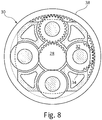
- the epicyclic gearbox 30 is shown by way of example in greater detail in Figure 8 .
- Each of the sun gear 28, planet gears 32 and ring gear 38 comprise teeth about their periphery to intermesh with the other gears. However, for clarity only exemplary portions of the teeth are illustrated in Figure 8 .
- Practical applications of a planetary epicyclic gearbox 30 generally comprise at least three planet gears 32.
- the epicyclic gearbox 30 illustrated by way of example in Figures 7 and 8 is of the planetary type, in that the planet carrier 34 is coupled to an output shaft via linkages 36, with the ring gear 38 fixed.
- the epicyclic gearbox 30 may be a star arrangement, in which the planet carrier 34 is held fixed, with the ring (or annulus) gear 38 allowed to rotate. In such an arrangement the fan 23 is driven by the ring gear 38.
- the gearbox 30 may be a differential gearbox in which the ring gear 38 and the planet carrier 34 are both allowed to rotate.
- any suitable arrangement may be used for locating the gearbox 30 in the engine 10 and/or for connecting the gearbox 30 to the engine 10.
- the connections (such as the linkages 36, 40 in the Figure 7 example) between the gearbox 30 and other parts of the engine 10 (such as the input shaft 26, the output shaft and the fixed structure 24) may have any desired degree of stiffness or flexibility.
- any suitable arrangement of the bearings between rotating and stationary parts of the engine may be used, and the disclosure is not limited to the exemplary arrangement of Figure 7 .
- the gearbox 30 has a star arrangement (described above)
- the skilled person would readily understand that the arrangement of output and support linkages and bearing locations would typically be different to that shown by way of example in Figure 7 .
- the present disclosure extends to a gas turbine engine having any arrangement of gearbox styles (for example star or planetary), support structures, input and output shaft arrangement, and bearing locations.
- gearbox styles for example star or planetary
- support structures for example star or planetary
- input and output shaft arrangement for example star or planetary
- bearing locations for example star or planetary
- the gearbox may drive additional and/or alternative components (e.g. the intermediate pressure compressor and/or a booster compressor).
- additional and/or alternative components e.g. the intermediate pressure compressor and/or a booster compressor.
- gas turbine engines to which the present disclosure may be applied may have alternative configurations.
- such engines may have an alternative number of compressors and/or turbines and/or an alternative number of interconnecting shafts.
- the gas turbine engine shown in Figure 6 has a split flow nozzle 20, 22 meaning that the flow through the bypass duct 22 has its own nozzle that is separate to and radially outside the core engine nozzle 20.
- this is not limiting, and any aspect of the present disclosure may also apply to engines in which the flow through the bypass duct 22 and the flow through the core 11 are mixed, or combined, before (or upstream of) a single nozzle, which may be referred to as a mixed flow nozzle.
- One or both nozzles may have a fixed or variable area.
- the described example relates to a turbofan engine, the disclosure may apply, for example, to any type of gas turbine engine, such as an open rotor (in which the fan stage is not surrounded by a nacelle) or turboprop engine, for example.
- the gas turbine engine 10 may not comprise a gearbox 30.
- the geometry of the gas turbine engine 10, and components thereof, is defined by a conventional axis system, comprising an axial direction (which is aligned with the rotational axis 9), a radial direction (in the bottom-to-top direction in Figure 6 ), and a circumferential direction (perpendicular to the page in the Figure 6 view).
- the axial, radial and circumferential directions are mutually perpendicular.
- FIG 9 shows an aircraft 8 in the form of a passenger aircraft.
- Aircraft 8 comprises several (i.e., two) gas turbine engines 10 in accordance with Figures 6 to 8 .
- the identification of the out-of-range mode shape(s) may target the stiffness and mass distributions may result in an effective reduction of the vibration throughout wide gas turbine engine 10 speed ranges where vibrations are deemed to be critical for the engine operation.
- the invention may be applied particularly to components of gas turbines, such as gas turbine engines, and power plants, rigs , engine mounts, large frames, buildings, civil structures, as well as in turbines, pumps, bearings, accessory and power gearboxes and others, but it can also be applied to components of other machines, in particular any type of engine. It is also worth noting that the methods described herein can optionally be used to redesign a component for retrofitting a part, e.g., when it has been found that the part vibrates critically in use.
- components particularly suitable for being redesigned as described herein are housings, static structures, struts, vanes and blades.
- the modification of geometry upon mode-shape patterns may further be combined with the use of composite materials or single crystals (e.g. for blades).
Abstract
Description
- The present disclosure relates to a method for designing a component, to a method for manufacturing a component, and to a component.
- A common problem, in particular in the field of rotating machinery, is controlling the level of vibration. Vibration may be caused by imbalances of components of the machinery, such as, e.g., a shaft, compressor and turbine discs and blades in gas turbine engines, and also external forcing such as, e.g., aircraft maneuvers and aerodynamic forces in an aircraft with the gas turbine engine. Damping systems such as fluid dampers are commonly employed to reduce vibrations.
- Vibrations are specifically pronounced at particular rotational speeds and/or frequencies, known as "critical" speeds, in view of resonances of the rotating system. At the critical speeds systems commonly vibrate in resonance, a condition at which vibrations are sustained by the system internal vibratory response determined by the designed stiffness, inertia and damping. The damping system is commonly designed such that its capabilities are not exceeded in use. In many cases the damping system and other components, such as a supporting structure, correspondingly have a relatively high weight. In many fields however, for example, aerospace, weight is an important consideration.
- It is an object to reduce vibrations with a lightweight component design.
- According an aspect there is provided a method for manufacturing a component. The method comprises designing or receiving a model of the component (e.g., a 3d-CAD model); determining, e.g., by computer simulation, at least one mode shape of the model; redesigning the model based on the determined at least one mode shape to obtain a redesigned model of the component; and manufacturing the component in accordance with the redesigned model.
- This is based on the finding that a vibrational response of a component may particularly effectively be reduced by adapting the geometry of the component to one or more of the mode shapes it has without the modification.
- The method provides a component design that allows to reduce vibration in resonance by means of variating the distribution of stiffness and/or mass at one or more components (e.g., of an engine), following the paths that are defined by one or more of its mode shapes.
- Given a certain object or structure, e.g. an engine component, a mode shape (defined by an eigenvector) corresponds to the characteristic deformation pattern at which the component vibrates when a correspondent natural frequency (defined by an eigenvalue) is excited in resonance. In addition to resonances, which are commonly unwanted conditions during operation, aircraft engines repeatedly undergo vibration excited by transient loads such as aircraft maneuvers, speed regulations or control systems interactions, which might be repeated several time per flight, causing fatigue and a eventually loss of the engine structural integrity.
- The mode shapes of a mechanical arrangement completely define the free and forced response of a mechanical system, being the free vibratory response defined a linear combination of mode shapes (Eq. 1), which depends on the boundary conditions (e.g., initial deformation and velocity).

- A peculiar property of the mode shapes is the orthogonality with respect to the mass and stiffness matrixes of the mechanical arrangement (e.g., a component or a sub assembly).

- The property of the mode shape orthogonality that is defined by Eq. 2 implies that the product of two different mode shapes over a period of the vibration is always equal to zero. In the physical domain of the vibration this represents the antagonism between two different mode shapes that cannot coexist at the same time.
- In fact, when the initial deformation of an unforced system is given reproducing one of the mode shapes, the response at the other mode is, as the peculiar inertia and stiffness equilibrium cannot take place at the same time. Hence the transient vibration takes place at the frequency of the mode shape that has been used for the initial excitation.
- Similarly, if a mode shape deformation is forced into the component by means of design, the other modes shapes can be advantageously disrupted, with the benefit of reducing critical vibration in a broad speed range.
- The Finite Element Modal Analysis is a calculation that can be carried out on engine subsystems and components in order to obtain their natural frequencies (eigenvalues) and correspondent mode shapes (eigenvectors). The characteristic vibratory response of a component includes a complex deformation that is a linear combination of its mode shapes, each one vibrating on at its own frequency. When, in the example of an engine, the engine speed is being variating and a resonance condition, or critical speed, is hit, the deformation of the component that generates vibration becomes coincident with the mode shape correspondent to the natural frequency that is being excited, as determined by the connections with the other engine components.
- The model may be redesigned in accordance with a pattern of the at least one mode shape. For example, the model is redesigned so that a stiffness and/or mass distribution follows the particular deformation pattern of the at least one mode shape.
- The at least one mode shape may be a non-critical mode shape. Optionally, one mode shape (e.g., a non-critical mode shape) is selected out of a plurality of mode shapes. The selected mode shape may be one that is able to disrupt the vibration due to one or more critical mode shapes excited in resonance.
- Determining one or more mode shapes of the component may be performed outside of a normal operating range of an operating condition of the component. This may comprise determining vibrational frequencies experienced in an operating range of the component. The operating condition may be a speed of an engine, wherein the component is a part of the engine. The operating condition may alternatively be a frequency of an excitation of the component (which, in turn may depend of an engine speed).
- Redesigning the model can be performed so as to adjust a stiffness of the component in accordance with the at least one out-of-operating-range mode shape. It is possible to reduce or eliminate vibrations and/or critical harmonics, at several speeds e.g. of a gas turbine having the component, within the operating range. It has been found that by taking into account mode shapes outside of operational ranges, the vibrational response of components within their operational range may be tuned so that potentially critical mode shapes within the operational range may be effectively disrupted.
- Redesigning the model may comprise modifying a geometry and/or a mass distribution of the component and/or the choice of a material of the component. For example, the shape and/or material thickness may be adapted to the at least one mode shape.
- Redesigning the model may also comprise modifying a stiffness, in particular a global stiffness and/or a local stiffness.
- The stiffness can be modified in a simple way by adding or removing reinforcement and/or by opportunely modifying the shape of the existing surface.
- The method optionally further comprises checking that a vibrational response of the component within an operating range is reduced after the redesigning, in particular below a predetermined threshold. If this is not the case, the method may repeat the step of determining a mode shape and/or of redesigning the model.
- The method optionally further comprises iteratively performing the steps of determining and/or redesigning and/or checking several times, e.g., two, three, four, five or more times.
- Optionally, the component is selected from a plurality of components before the model of this component is redesigned (in particular before the model of the component is designed). For example, the component is selected from a plurality of components of a gas turbine by determining one or more components of the gas turbine which produce(s) vibration and/or critical harmonics by a design failure mode and effects analysis, DFMEA, and/or by a finite element analysis, FEA. Alternatively or in addition, determining one or more mode shapes of the selected model may be performed by DFMEA and/or FEA.
- After manufacturing the component or of a plurality of components, the component or the plurality of such components may be mounted at a machine, e.g. at a gas turbine, in particular a gas turbine engine of an aircraft.
- According to an aspect, a component manufactured in accordance with the above method is provided. As a result, the shape of the component corresponds to a mode shape, e.g. with alternating local variations of the shape and/or stiffness.
- The component may particularly be a component of a gas turbine engine, in particular of a power gearbox thereof, driven by a compressor via a shaft. For example, the component is a ring gear mounting, in particular of such a power gearbox. Vibrations may be particularly difficult to reduce in such gearboxes, in particular vibrations of the ring gear mounting. By designing and manufacturing particularly the ring gear mounting in accordance with the methods described herein, it is possible to substantially decrease vibrations and the weight of the ring gear mounting (and, eventually, also further components). This may increase the lifetime of the power gearbox and/or the time between two maintenances.
- According to an aspect, a gas turbine, in particular a gas turbine engine for an aircraft is provided, which comprises one or more components as described herein.
- The skilled person will appreciate that except where mutually exclusive, a feature or parameter described in relation to any one of the above aspects may be applied to any other aspect. Furthermore, except where mutually exclusive, any feature or parameter described herein may be applied to any aspect and/or combined with any other feature or parameter described herein.
- Embodiments will now be described by way of example only, with reference to the Figures, in which:
- Figure 1
- shows various mode shapes for components with basic circular geometries;
- Figure 2
- is a method for designing and manufacturing a component;
- Figure 3
- is a method for designing and manufacturing a component;
- Figures 4A to 4C
- show a component without excitation (
Figure 4A ), with excitation of a mode shape (Figure 4B ) and a cross section ofFigure 4B (Figure 4C ); - Figures 5A and 5B
- show a component in the form of a ring gear mount without excitation (
Figure 5A ) and with excitation of a mode shape (Figure 5B ); - Figure 6
- is a sectional side view of a gas turbine engine;
- Figure 7
- is a close up sectional side view of an upstream portion of a gas turbine engine;
- Figure 8
- is a partially cut-away view of a gearbox for a gas turbine engine; and
- Figure 9
- is an aircraft having a plurality of gas turbine engines.
- For a dynamical system, a mode is a standing wave state of excitation, in which all parts of the system will be affected sinusoidally under a specified fixed frequency. A mode of vibration is characterized by a modal frequency and a mode shape. Given a certain component (in particular a certain engine component), a mode shape corresponds to a characteristic deformation at which the component vibrates when one of its natural frequencies is excited. The vibratory response of the component corresponds to a linear combination of all mode shapes.
-
Figure 1 shows in four rows examples of different components generally having the shape of a disc. The different columns each show the excitation of a certain mode of vibration, wherein the corresponding mode shapes are indicated. - Referring to the first row showing a component in the form of a disc with a hole in the middle as an example, the first mode has a mode shape comprising a symmetric U-shaped deformation. The second mode has a mode shape with two upward deformations and two downward deformations (i.e., each two maxima and minima). The third mode has a mode shape with four maxima and minima, the mode shape shown in the fourth column of the first row has each six maxima and minima. According to aspects described herein, a component, such as one of the components shown in
Figure 1 , may be redesigned in accordance with one or more of the mode shapes. As a result, the response of the component at other frequencies and thus the overall strength of vibrations of the component may be reduced. Due to eigenvalues orthogonality and Fourier theory applied to system dynamics, a possibility to polarize a system response is based on the idea to force the deformation of a structure to assume a shape similar to one of its mode shapes. -
Figure 2 shows amethod 100 for designing and manufacturing a component. The method comprises the following steps: - Step 101: designing or receiving a model of the component. The model may be a geometric representation of the component, e.g. in the form of a CAD drawing. The model may be specifically designed or retrieved, e.g., from a database.
- Step 102: determining one or more mode shapes of the model. This may comprise performing a finite elements modal analysis. The mode shape may be a non-critical mode shape. The component may be adapted to operate at a predetermined operating range of a given parameter, such as the frequency of an excitation. In gas turbines, for example, a shaft may rotate at a specific range of speeds, wherein the rotation of the shaft may excite a vibration of the component. The determination of the mode shape may be made at values of the parameter outside the operating range (and therefore unlikely to be excited during operation of the machine having the component).
- Step 103: redesigning the model based on the determined at least one mode shape (e.g., one mode shape or a combination of several mode shapes) to obtain a redesigned model of the component. This may comprise modifying the geometry and/or other parameters of the model. In particular, redesigning the model may be based on a pattern of the at least one mode shape. This can be done by adjusting a stiffness of the component in accordance with the at least one (e.g., out of operating range) mode shape. As an example, redesigning the model may comprise modifying the geometry and/or mass distribution defined by the model. Optionally, redesigning the model comprises modifying a stiffness defined by the model. The stiffness may be modified by adding or removing a reinforcement structure, e.g., a rib and/or locally increased thickness, and/or by a local hardening of the material. Purely by way of example, it may be found that for the component shown in the first row of
Figure 1 , the operating range comprises frequencies and intensities that lead to the first, second and third modes. The third mode, e.g., may be found to be a critical mode (e.g., potentially leading to increased wear and/or reduced lifetime). The fourth mode may be found to be outside the operating range and non-critical. The model of the component may be redesigned so as to have the form described by the fourth mode shape. This may disturb the vibrational response of the component in such a way that the third mode becomes no longer critical under the same operating conditions as before. Indeed, a plurality of critical mode shapes may be addressed at the same time by providing the redesigned, modified component geometry. - Step 104: Checking that a vibrational response of the component is reduced, e.g., within the operating range. This may include the comparison of a parameter of the vibrational response with a predetermined threshold. When it is determined at
step 104 that the vibrational response is reduced, e.g., to a predetermined extend, the method continues to step 105. Otherwise, it can optionally repeatsteps 102 to 104 at least one time, e.g., iteratively. - Step 105: providing the redesigned model. As an example, the model may be provided in the form of computer-readable instructions being indicative for the geometry of the component. The computer-readable instructions may be provided to a manufacturing machine or the like.
- Step 106: manufacturing the component in accordance with the redesigned model. This may be done by means of a machine that received the redesigned model.
-
Figure 3 shows amethod 200 to design and manufacture a component. - The
method 200 starts at step 201 (component design). Atstep 201, a component is designed by providing, designing or otherwise creating a model of the component. The model may comprise a set of definitions that characterize the physical properties, in particular the geometry of the component to be manufactured. - The model is provided to a finite elements modal analysis performed at step 202 (FE modal analysis to determine mode shapes and natural frequencies). Therein the modal analysis may determine mode shapes and natural frequencies of a component having the design of the model. This may be performed by a computer.
- At optional step 203 (harmonic response), a harmonic response is determined, e.g., by a harmonic response analysis.
- At optional step 205 (maximum stress profiles), maximum stress profiles may be determined and/or provided, e.g. a maximum stress profile of the component to be manufactured. At further optional step 206 (speed envelope), a speed envelope, e.g., of a gas turbine for which the component is to be manufactured for (and during a flight), may be determined and/or provided. At further optional step 207 (dimensional tolerances), dimensional tolerances of the component to be manufactured and/or of adjacent components in the engine are determined and/or provided.
- The results of the analyses at
steps 202 and, optionally 203, and, optionally, the outcome ofsteps step 204. Therein, a mode shape may be determined to be critical when it creates or potentially leads to a critical resonance, e.g. having a destructive effect on the component or adjacent components in the engine (or, in general, machine). - Further input to the critical mode shapes identification at
step 204 may be provided as test results from tests in steps 211 (engine subsystem test), 212 (engine test) and/or 213 (flight test, in particular for a retrofit). - At
steps Steps 211 to 213 may provide hardware-based tests that are performed based on a given component design, represented by the model provided in step 201 (or step 101 inFigure 1 ). - Based on some of, or all of the results provided, at
step 204, critical mode shapes are identified. - The mode shape(s) on which to variate the geometry of the component may be identified upon conjoint consideration of an operational speed range and the identification of critical mode shapes that require to be eliminated, or reduced to a maximum extent. The mode shape chosen for altering the geometry may be a non-critical one, out of range and able to mismatching the geometrical periodicities expected to excite resonances during operation. In addition, the mode shape for the stiffness paths may be chosen in order to optimize the disruption of other critical mode shapes at other frequencies.
- In case that critical mode shapes are identified at
step 204, the method proceeds to step 208. At step 208 (identification of the mode shape for modal stiffening), a mode shape to be used for a mode-shape specific component stiffening is identified. To this end, the results or a subset of the results of the performance ofstep 202 may be provided to be used atstep 208. - The identified mode shape (e.g., as shown in the first row, third column of
Figure 1 ), is then provided to a mode-shaped design application atstep 209. Therein, the component design, i.e., the model of the component, is redesigned (modified) so as to at least partially follow the form of the mode shape. An excitation of the mode shape (e.g., a maximum deflection) may be translated to or "frozen" in the redesigned model of the component. - The redesigned model and the outcome of
step 204 are provided and analyzed at step 210 (vibration reduced to target evaluation). Atstep 210, it is evaluated whether or not the vibration of the component according to the redesigned model in response to a given excitation meets a given target, e.g., is reduced so as to be below a predefined threshold. When this is the case, the redesigned model is provided (indicated as 214), for manufacturing the component in accordance with the redesigned model at step 215 (manufacturing). - If, however, the target is not met, the method may return to step 209 (and from there either to step 201 or to step 210) or to step 201.
-
Figures 4A to 4C show geometries of two versions of acomponent 50, in the present example a ring gear front diaphragm, having adisc portion 51 and acylindrical portion 52.Figure 4A shows thecomponent 50 in accordance with a model M. The model M is provided atstep method 100; 200 ofFigure 2 or3 . Themethod 100 ofFigure 2 or themethod 200 ofFigure 3 is then performed, wherein a redesigned model M' is created. Thecomponent 50 is manufactured in accordance with the redesigned model M'. This is shown inFigures 4B and 4C , wherein it becomes apparent that a portion of the model M', in this example, an outer ring section of thedisc portion 51, has been modified with respect to the original model M such that it assumes the pattern of a mode shape of thecomponent 50. In the example ofFigures 4B and 4C , the outer ring section is periodically bent inwards and outwards (in a 7-nodal diameter mode shape). The surface of the outer ring section follows the mode shape deformation of the unmodified component (seeFigure 4A ). -
Figure 4C shows an optional way of stiffening portions in accordance with a mode shape by adding one ormore reinforcements 53 in a pattern that corresponds to the mode shape (indicated by dashed lines). Thereinforcements 53 may be formed as stiffening ribs and/or local thickness variations. Another option is to arrange a composite material (or portions thereof) along the mode shape. -
Figures 5A and 5B show two versions of anothercomponent 60. Thiscomponent 60 is a ring gear mount for mounting aring gear 38 of a gearbox of a gas turbine engine to a stationary structure of the gas turbine engine by means of aflange 61. The gas turbine engine, gearbox andring gear 38 will be described in greater detail below with reference toFigures 6 to 8 . -
Figure 5A shows thecomponent 60 designed in accordance with a model M that has not yet been tuned on a mode shape, and excited in an operating range of frequencies and intensities. Local deformations are very pronounced and lead to stresses on thecomponent 60 which may reduce its lifetime. The mode shape is a critical 8-diameter mode shape. -
Figure 5B shows a version of thecomponent 60 manufactured in accordance with themethod 100; 200 ofFigure 2 or3 (in accordance with a redesigned model M') at the excitation as shown inFigure 5A . Stresses are more smoothly distributed over thecomponent 60, so that it can withstand the stresses more stably. Thus, the lifetime of thecomponent 60 according to the redesigned model M' may be increased. Alternatively or additionally, the weight of thecomponent 60 may be reduced. - It becomes apparent that by means of the method described herein, vibrations of the component can be optimized. Manufacturing a
component 50; 60 in accordance with themethod 100; 200 allows to reproduce a non-critical mode shape stiffness distribution. - In the
methods 100; 200, the whole distribution of stiffness of a non-critical mode shape can be used in order to alter the component stiffness and geometry so that the vibration due other, critical mode shapes cannot take place any longer, even if the natural frequency remains within the operational range. - This can be achieved particularly due to the principle of antagonism between different mode shapes. Stating in simplified words, if a mode shape exists, other mode shapes cannot take place at the same time or are minimized by being disrupted due to the presence of the other, non-critical mode shape. By this, the vibration by critical resonances due to other mode shapes may be damped. The non-critical mode shape becomes dominant at all speed as its stiffness has been "shaped" in the geometry. From the integration of the functional requirements of the component and the stiffness variation along the areas identified by a well-defined mode shape, it is possible to reduce the vibration in the frequency ranges where it is most needed. Thereby, several resonances may be addressed at the same time.
-
Figure 6 illustrates agas turbine engine 10 for an aircraft. Thegas turbine engine 10 has a principalrotational axis 9. Theengine 10 comprises anair intake 12 and apropulsive fan 23 that generates two airflows: a core airflow A and a bypass airflow B. Thegas turbine engine 10 comprises a core 11 that receives the core airflow A. Theengine core 11 comprises, in axial flow series, alow pressure compressor 14, a high-pressure compressor 15,combustion equipment 16, a high-pressure turbine 17, alow pressure turbine 19 and acore exhaust nozzle 20. Anacelle 21 surrounds thegas turbine engine 10 and defines abypass duct 22 and abypass exhaust nozzle 18. The bypass airflow B flows through thebypass duct 22. Thefan 23 is attached to and driven by thelow pressure turbine 19 via a shaft 26 (low-pressure shaft) and an epicyclic gearbox. - In use, the core airflow A is accelerated and compressed by the
low pressure compressor 14 and directed into thehigh pressure compressor 15 where further compression takes place. The compressed air exhausted from thehigh pressure compressor 15 is directed into thecombustion equipment 16 where it is mixed with fuel and the mixture is combusted. The resultant hot combustion products then expand through, and thereby drive, the high pressure andlow pressure turbines nozzle 20 to provide some propulsive thrust. Thehigh pressure turbine 17 drives thehigh pressure compressor 15 by a suitable interconnecting shaft 27 (high-pressure shaft). Thefan 23 generally provides the majority of the propulsive thrust. Theepicyclic gearbox 30 is a reduction gearbox. - The
gas turbine engine 10 comprises one or more components designed in accordance with themethod 100; 200 ofFigure 2 and/or 3, e.g. a ring gear mount of thegearbox 30. - An exemplary arrangement for a geared fan
gas turbine engine 10 is shown inFigure 7 . The low pressure turbine 19 (seeFigure 6 ) drives theshaft 26, which is coupled to a sun wheel, or sun gear, 28 of theepicyclic gear arrangement 30. Radially outwardly of thesun gear 28 and intermeshing therewith is a plurality of planet gears 32 that are coupled together by aplanet carrier 34. Theplanet carrier 34 constrains the planet gears 32 to precess around thesun gear 28 in synchronicity whilst enabling eachplanet gear 32 to rotate about its own axis. Theplanet carrier 34 is coupled vialinkages 36 to thefan 23 in order to drive its rotation about theengine axis 9. Radially outwardly of the planet gears 32 and intermeshing therewith is an annulus orring gear 38 that is coupled, via thering gear mount 60 andlinkages 40, to a stationary supportingstructure 24. - Note that the terms "low pressure turbine" and "low pressure compressor" as used herein may be taken to mean the lowest pressure turbine stages and lowest pressure compressor stages (i.e. not including the fan 23) respectively and/or the turbine and compressor stages that are connected together by the interconnecting
shaft 26 with the lowest rotational speed in the engine (i.e. not including the gearbox output shaft that drives the fan 23). In some literature, the "low pressure turbine" and "low pressure compressor" referred to herein may alternatively be known as the "intermediate pressure turbine" and "intermediate pressure compressor". Where such alternative nomenclature is used, thefan 23 may be referred to as a first, or lowest pressure, compression stage. - The
epicyclic gearbox 30 is shown by way of example in greater detail inFigure 8 . Each of thesun gear 28, planet gears 32 andring gear 38 comprise teeth about their periphery to intermesh with the other gears. However, for clarity only exemplary portions of the teeth are illustrated inFigure 8 . There are fourplanet gears 32 illustrated, although it will be apparent to the skilled reader that more or fewer planet gears 32 may be provided within the scope of the claimed invention. Practical applications of a planetaryepicyclic gearbox 30 generally comprise at least three planet gears 32. - The
epicyclic gearbox 30 illustrated by way of example inFigures 7 and8 is of the planetary type, in that theplanet carrier 34 is coupled to an output shaft vialinkages 36, with thering gear 38 fixed. However, any other suitable type ofepicyclic gearbox 30 may be used. By way of further example, theepicyclic gearbox 30 may be a star arrangement, in which theplanet carrier 34 is held fixed, with the ring (or annulus)gear 38 allowed to rotate. In such an arrangement thefan 23 is driven by thering gear 38. By way of further alternative example, thegearbox 30 may be a differential gearbox in which thering gear 38 and theplanet carrier 34 are both allowed to rotate. - It will be appreciated that the arrangement shown in
Figures 7 and8 is by way of example only, and various alternatives are within the scope of the present disclosure. Purely by way of example, any suitable arrangement may be used for locating thegearbox 30 in theengine 10 and/or for connecting thegearbox 30 to theengine 10. By way of further example, the connections (such as thelinkages Figure 7 example) between thegearbox 30 and other parts of the engine 10 (such as theinput shaft 26, the output shaft and the fixed structure 24) may have any desired degree of stiffness or flexibility. By way of further example, any suitable arrangement of the bearings between rotating and stationary parts of the engine (for example between the input and output shafts from the gearbox and the fixed structures, such as the gearbox casing) may be used, and the disclosure is not limited to the exemplary arrangement ofFigure 7 . For example, where thegearbox 30 has a star arrangement (described above), the skilled person would readily understand that the arrangement of output and support linkages and bearing locations would typically be different to that shown by way of example inFigure 7 . - Accordingly, the present disclosure extends to a gas turbine engine having any arrangement of gearbox styles (for example star or planetary), support structures, input and output shaft arrangement, and bearing locations.
- Optionally, the gearbox may drive additional and/or alternative components (e.g. the intermediate pressure compressor and/or a booster compressor).
- Other gas turbine engines to which the present disclosure may be applied may have alternative configurations. For example, such engines may have an alternative number of compressors and/or turbines and/or an alternative number of interconnecting shafts. By way of further example, the gas turbine engine shown in
Figure 6 has asplit flow nozzle bypass duct 22 has its own nozzle that is separate to and radially outside thecore engine nozzle 20. However, this is not limiting, and any aspect of the present disclosure may also apply to engines in which the flow through thebypass duct 22 and the flow through the core 11 are mixed, or combined, before (or upstream of) a single nozzle, which may be referred to as a mixed flow nozzle. One or both nozzles (whether mixed or split flow) may have a fixed or variable area. Whilst the described example relates to a turbofan engine, the disclosure may apply, for example, to any type of gas turbine engine, such as an open rotor (in which the fan stage is not surrounded by a nacelle) or turboprop engine, for example. In some arrangements, thegas turbine engine 10 may not comprise agearbox 30. - The geometry of the
gas turbine engine 10, and components thereof, is defined by a conventional axis system, comprising an axial direction (which is aligned with the rotational axis 9), a radial direction (in the bottom-to-top direction inFigure 6 ), and a circumferential direction (perpendicular to the page in theFigure 6 view). The axial, radial and circumferential directions are mutually perpendicular. -
Figure 9 shows anaircraft 8 in the form of a passenger aircraft.Aircraft 8 comprises several (i.e., two)gas turbine engines 10 in accordance withFigures 6 to 8 . - The identification of the out-of-range mode shape(s) may target the stiffness and mass distributions may result in an effective reduction of the vibration throughout wide
gas turbine engine 10 speed ranges where vibrations are deemed to be critical for the engine operation. - It will be understood that the invention is not limited to the embodiments above-described and various modifications and improvements can be made without departing from the concepts described herein. Except where mutually exclusive, any of the features may be employed separately or in combination with any other features and the disclosure extends to and includes all combinations and sub-combinations of one or more features described herein.
- For example, the invention may be applied particularly to components of gas turbines, such as gas turbine engines, and power plants, rigs , engine mounts, large frames, buildings, civil structures, as well as in turbines, pumps, bearings, accessory and power gearboxes and others, but it can also be applied to components of other machines, in particular any type of engine. It is also worth noting that the methods described herein can optionally be used to redesign a component for retrofitting a part, e.g., when it has been found that the part vibrates critically in use.
- For aircraft engines, such as gas turbine engines, components particularly suitable for being redesigned as described herein are housings, static structures, struts, vanes and blades. The modification of geometry upon mode-shape patterns may further be combined with the use of composite materials or single crystals (e.g. for blades).
-
- 8
- airplane
- 9
- principal rotational axis
- 10
- gas turbine engine
- 11
- engine core
- 12
- air intake
- 14
- low-pressure compressor
- 15
- high-pressure compressor
- 16
- combustion equipment
- 17
- high-pressure turbine
- 18
- bypass exhaust nozzle
- 19
- low-pressure turbine
- 20
- core exhaust nozzle
- 21
- nacelle
- 22
- bypass duct
- 23
- propulsive fan
- 24
- stationary support structure
- 26
- shaft
- 27
- interconnecting shaft
- 28
- sun gear
- 30
- gearbox
- 32
- planet gears
- 34
- planet carrier
- 36
- linkages
- 38
- ring gear
- 40
- linkages
- 50
- component
- 51
- disc portion
- 52
- cylindrical portion
- 53
- reinforcement
- 60
- component
- 61
- flange
- A
- core airflow
- B
- bypass airflow
- M
- model
- M'
- redesigned model
Claims (14)
- A method (100; 200) for manufacturing a component (50; 60), comprising:- designing or receiving (101; 201) a model (M) of the component (50; 60);- determining (102; 202) at least one mode shape of at least a portion of the model (M);- redesigning (103; 209) the model (M) based on the determined at least one mode shape to obtain a redesigned model (M') of the component (50; 60); and- manufacturing (106) the component (50; 60) in accordance with the redesigned model (M').
- The method (100; 200) according to claim 1, wherein the model (M) is redesigned (103; 209) in accordance with a pattern of the at least one mode shape.
- The method (100; 200) according to claim 1 or 2, wherein the at least one mode shape is non-critical.
- The method (100; 200) according to any of the preceding claims, wherein determining (102; 202) one or more mode shapes of the component (50; 60) is performed outside of a normal operating range with respect to an operating condition of the component.
- The method (100; 200) according to claim 4, wherein redesigning (103; 209) the model (M) is performed so as to adjust component stiffness in accordance with the at least one out of operating range mode shape.
- The method (100; 200) according to any of the preceding claims, wherein redesigning (103; 209) the model comprises modifying a geometry and/or a mass distribution.
- The method (100; 200) according to any of the preceding claims, wherein redesigning (103; 209) the model comprises modifying a stiffness.
- The method (100; 200) according to claim 7, wherein the stiffness is modified by adding or removing a reinforcement (53).
- The method (100; 200) according to any of the preceding claims, further comprising checking (104) that a vibrational response of the component (50; 60) within an operating range is reduced after redesigning the model (M).
- The method (100; 200) according to any of the preceding claims, further comprising iteratively performing the steps of determining (102), redesigning (103) and/or checking (104) several times.
- The method (100; 200) according to any of the preceding claims, wherein before the model (M) is redesigned, the component (50; 60) is selected from a plurality of components by determining a component of a gas turbine (10) which produces vibration harmonics and/or critical harmonics by a design failure mode and effects analysis, DFMEA, and/or a finite element analysis, FEA.
- A component (50; 60) manufactured in accordance with any of the preceding claims.
- The component (60) of claim 12, wherein the component (60) is a component of a gas turbine engine (10) power gearbox (30).
- A gas turbine (10) comprising on or more components (60) of claim 12 or 13.
Priority Applications (3)
| Application Number | Priority Date | Filing Date | Title |
|---|---|---|---|
| EP19175620.4A EP3741981B1 (en) | 2019-05-21 | 2019-05-21 | Mode-shaped components |
| US16/868,723 US11645436B2 (en) | 2019-05-21 | 2020-05-07 | Mode-shaped components |
| CN202010435312.0A CN111985046A (en) | 2019-05-21 | 2020-05-21 | Modularly formed component |
Applications Claiming Priority (1)
| Application Number | Priority Date | Filing Date | Title |
|---|---|---|---|
| EP19175620.4A EP3741981B1 (en) | 2019-05-21 | 2019-05-21 | Mode-shaped components |
Publications (2)
| Publication Number | Publication Date |
|---|---|
| EP3741981A1 true EP3741981A1 (en) | 2020-11-25 |
| EP3741981B1 EP3741981B1 (en) | 2023-03-15 |
Family
ID=66676190
Family Applications (1)
| Application Number | Title | Priority Date | Filing Date |
|---|---|---|---|
| EP19175620.4A Active EP3741981B1 (en) | 2019-05-21 | 2019-05-21 | Mode-shaped components |
Country Status (3)
| Country | Link |
|---|---|
| US (1) | US11645436B2 (en) |
| EP (1) | EP3741981B1 (en) |
| CN (1) | CN111985046A (en) |
Citations (3)
| Publication number | Priority date | Publication date | Assignee | Title |
|---|---|---|---|---|
| US20050096891A1 (en) * | 2003-10-29 | 2005-05-05 | George Simpson | Design of vanes for exposure to vibratory loading |
| GB2490127A (en) * | 2011-04-19 | 2012-10-24 | Rolls Royce Plc | Aerofoil assembly |
| US20180038382A1 (en) * | 2016-08-08 | 2018-02-08 | United Technologies Corporation | Mistuned laminate airfoil |
Family Cites Families (11)
| Publication number | Priority date | Publication date | Assignee | Title |
|---|---|---|---|---|
| AU5006900A (en) * | 1999-05-13 | 2000-12-05 | Rolls-Royce Corporation | Method for designing a cyclic symmetric structure |
| GB0019434D0 (en) * | 2000-08-09 | 2000-09-27 | Rolls Royce Plc | A device and method for fatigue testing of materials |
| US7280950B2 (en) * | 2004-01-22 | 2007-10-09 | Electro-Motive Diesel, Inc. | Locomotive diesel engine turbocharger and turbine stage constructed with turbine blade vibration suppression methodology |
| US8209839B1 (en) * | 2006-11-28 | 2012-07-03 | Florida Turbine Technologies, Inc. | Process for re-designing a distressed component used under thermal and structural loading |
| WO2009059604A1 (en) * | 2007-11-09 | 2009-05-14 | Vestas Wind Systems A/S | A structural mat for reinforcing a wind turbine blade structure, a wind turbine blade and a method for manufacturing a wind turbine blade |
| JP2011042138A (en) * | 2009-08-24 | 2011-03-03 | Canon Inc | Method of manufacturing optical element and image forming apparatus |
| US8713511B1 (en) * | 2011-09-16 | 2014-04-29 | Suvolta, Inc. | Tools and methods for yield-aware semiconductor manufacturing process target generation |
| US10423730B2 (en) * | 2014-10-02 | 2019-09-24 | Siemens Industry Software Nv | Contact modeling between objects |
| US20180314767A1 (en) * | 2017-04-28 | 2018-11-01 | General Electric Company | Systems and methods for improved characteristic accountability & verification (ecav) system |
| US11280751B2 (en) * | 2018-12-04 | 2022-03-22 | General Electric Company | System and method for optimizing a manufacturing process based on an inspection of a component |
| US11797728B2 (en) * | 2020-04-30 | 2023-10-24 | Ansys, Inc. | Automating extraction of material model coefficients for simulations |
-
2019
- 2019-05-21 EP EP19175620.4A patent/EP3741981B1/en active Active
-
2020
- 2020-05-07 US US16/868,723 patent/US11645436B2/en active Active
- 2020-05-21 CN CN202010435312.0A patent/CN111985046A/en active Pending
Patent Citations (3)
| Publication number | Priority date | Publication date | Assignee | Title |
|---|---|---|---|---|
| US20050096891A1 (en) * | 2003-10-29 | 2005-05-05 | George Simpson | Design of vanes for exposure to vibratory loading |
| GB2490127A (en) * | 2011-04-19 | 2012-10-24 | Rolls Royce Plc | Aerofoil assembly |
| US20180038382A1 (en) * | 2016-08-08 | 2018-02-08 | United Technologies Corporation | Mistuned laminate airfoil |
Also Published As
| Publication number | Publication date |
|---|---|
| EP3741981B1 (en) | 2023-03-15 |
| US20200372192A1 (en) | 2020-11-26 |
| CN111985046A (en) | 2020-11-24 |
| US11645436B2 (en) | 2023-05-09 |
Similar Documents
| Publication | Publication Date | Title |
|---|---|---|
| CN101333943B (en) | Turbomachine stator damper device | |
| EP3992594A1 (en) | System and method for detecting vibrations in rotating machinery | |
| US11645436B2 (en) | Mode-shaped components | |
| US20120288373A1 (en) | Rotor with asymmetric blade spacing | |
| US20200232883A1 (en) | Detecting an object impact event | |
| Holzinger et al. | Self-excited blade vibration experimentally investigated in transonic compressors: Rotating instabilities and flutter | |
| US10267155B2 (en) | Method for intentionally mistuning a turbine blade of a turbomachine | |
| US11898498B2 (en) | Method and system for reducing cross-shaft vibrations | |
| EP3825579A1 (en) | Method and system for reducing vibrations in rotating machinery | |
| US20100050594A1 (en) | Method for reducing the vibration levels of a propfan of contrarotating bladed disks of a turbine engine | |
| US10781827B1 (en) | Gas turbine engine airfoil frequency design | |
| US10697304B1 (en) | Gas turbine engine airfoil frequency design | |
| US10788049B1 (en) | Gas turbine engine airfoil frequency design | |
| GB2545804A (en) | Instrumented flow passage of a turbine engine | |
| US10982551B1 (en) | Turbomachine blade | |
| Ivanov et al. | Nonlinear reduced dynamic model of turbofan engine for investigation of engine structural frame vibrations after fan blade out event | |
| US10683761B1 (en) | Gas turbine engine airfoil frequency design | |
| US10815787B1 (en) | Gas turbine engine airfoil frequency design | |
| US10711623B1 (en) | Gas turbine engine airfoil frequency design | |
| US10669856B1 (en) | Gas turbine engine airfoil frequency design | |
| US10801364B1 (en) | Gas turbine engine airfoil frequency design | |
| US10815785B1 (en) | Gas turbine engine airfoil frequency design | |
| US10865809B1 (en) | Gas turbine engine airfoil frequency design | |
| US10774651B1 (en) | Gas turbine engine airfoil frequency design | |
| US10760429B1 (en) | Gas turbine engine airfoil frequency design |
Legal Events
| Date | Code | Title | Description |
|---|---|---|---|
| PUAI | Public reference made under article 153(3) epc to a published international application that has entered the european phase |
Free format text: ORIGINAL CODE: 0009012 |
|
| STAA | Information on the status of an ep patent application or granted ep patent |
Free format text: STATUS: THE APPLICATION HAS BEEN PUBLISHED |
|
| AK | Designated contracting states |
Kind code of ref document: A1 Designated state(s): AL AT BE BG CH CY CZ DE DK EE ES FI FR GB GR HR HU IE IS IT LI LT LU LV MC MK MT NL NO PL PT RO RS SE SI SK SM TR |
|
| AX | Request for extension of the european patent |
Extension state: BA ME |
|
| STAA | Information on the status of an ep patent application or granted ep patent |
Free format text: STATUS: REQUEST FOR EXAMINATION WAS MADE |
|
| 17P | Request for examination filed |
Effective date: 20210517 |
|
| RBV | Designated contracting states (corrected) |
Designated state(s): AL AT BE BG CH CY CZ DE DK EE ES FI FR GB GR HR HU IE IS IT LI LT LU LV MC MK MT NL NO PL PT RO RS SE SI SK SM TR |
|
| GRAP | Despatch of communication of intention to grant a patent |
Free format text: ORIGINAL CODE: EPIDOSNIGR1 |
|
| STAA | Information on the status of an ep patent application or granted ep patent |
Free format text: STATUS: GRANT OF PATENT IS INTENDED |
|
| INTG | Intention to grant announced |
Effective date: 20221004 |
|
| GRAS | Grant fee paid |
Free format text: ORIGINAL CODE: EPIDOSNIGR3 |
|
| GRAA | (expected) grant |
Free format text: ORIGINAL CODE: 0009210 |
|
| STAA | Information on the status of an ep patent application or granted ep patent |
Free format text: STATUS: THE PATENT HAS BEEN GRANTED |
|
| AK | Designated contracting states |
Kind code of ref document: B1 Designated state(s): AL AT BE BG CH CY CZ DE DK EE ES FI FR GB GR HR HU IE IS IT LI LT LU LV MC MK MT NL NO PL PT RO RS SE SI SK SM TR |
|
| REG | Reference to a national code |
Ref country code: CH Ref legal event code: EP Ref country code: GB Ref legal event code: FG4D |
|
| REG | Reference to a national code |
Ref country code: DE Ref legal event code: R096 Ref document number: 602019026330 Country of ref document: DE |
|
| REG | Reference to a national code |
Ref country code: IE Ref legal event code: FG4D |
|
| REG | Reference to a national code |
Ref country code: AT Ref legal event code: REF Ref document number: 1554130 Country of ref document: AT Kind code of ref document: T Effective date: 20230415 |
|
| REG | Reference to a national code |
Ref country code: LT Ref legal event code: MG9D |
|
| P01 | Opt-out of the competence of the unified patent court (upc) registered |
Effective date: 20230528 |
|
| REG | Reference to a national code |
Ref country code: NL Ref legal event code: MP Effective date: 20230315 |
|
| PG25 | Lapsed in a contracting state [announced via postgrant information from national office to epo] |
Ref country code: RS Free format text: LAPSE BECAUSE OF FAILURE TO SUBMIT A TRANSLATION OF THE DESCRIPTION OR TO PAY THE FEE WITHIN THE PRESCRIBED TIME-LIMIT Effective date: 20230315 Ref country code: NO Free format text: LAPSE BECAUSE OF FAILURE TO SUBMIT A TRANSLATION OF THE DESCRIPTION OR TO PAY THE FEE WITHIN THE PRESCRIBED TIME-LIMIT Effective date: 20230615 Ref country code: LV Free format text: LAPSE BECAUSE OF FAILURE TO SUBMIT A TRANSLATION OF THE DESCRIPTION OR TO PAY THE FEE WITHIN THE PRESCRIBED TIME-LIMIT Effective date: 20230315 Ref country code: LT Free format text: LAPSE BECAUSE OF FAILURE TO SUBMIT A TRANSLATION OF THE DESCRIPTION OR TO PAY THE FEE WITHIN THE PRESCRIBED TIME-LIMIT Effective date: 20230315 Ref country code: HR Free format text: LAPSE BECAUSE OF FAILURE TO SUBMIT A TRANSLATION OF THE DESCRIPTION OR TO PAY THE FEE WITHIN THE PRESCRIBED TIME-LIMIT Effective date: 20230315 |
|
| PGFP | Annual fee paid to national office [announced via postgrant information from national office to epo] |
Ref country code: FR Payment date: 20230523 Year of fee payment: 5 Ref country code: DE Payment date: 20230530 Year of fee payment: 5 |
|
| REG | Reference to a national code |
Ref country code: AT Ref legal event code: MK05 Ref document number: 1554130 Country of ref document: AT Kind code of ref document: T Effective date: 20230315 |
|
| PG25 | Lapsed in a contracting state [announced via postgrant information from national office to epo] |
Ref country code: SE Free format text: LAPSE BECAUSE OF FAILURE TO SUBMIT A TRANSLATION OF THE DESCRIPTION OR TO PAY THE FEE WITHIN THE PRESCRIBED TIME-LIMIT Effective date: 20230315 Ref country code: NL Free format text: LAPSE BECAUSE OF FAILURE TO SUBMIT A TRANSLATION OF THE DESCRIPTION OR TO PAY THE FEE WITHIN THE PRESCRIBED TIME-LIMIT Effective date: 20230315 Ref country code: GR Free format text: LAPSE BECAUSE OF FAILURE TO SUBMIT A TRANSLATION OF THE DESCRIPTION OR TO PAY THE FEE WITHIN THE PRESCRIBED TIME-LIMIT Effective date: 20230616 Ref country code: FI Free format text: LAPSE BECAUSE OF FAILURE TO SUBMIT A TRANSLATION OF THE DESCRIPTION OR TO PAY THE FEE WITHIN THE PRESCRIBED TIME-LIMIT Effective date: 20230315 |
|
| PG25 | Lapsed in a contracting state [announced via postgrant information from national office to epo] |
Ref country code: SM Free format text: LAPSE BECAUSE OF FAILURE TO SUBMIT A TRANSLATION OF THE DESCRIPTION OR TO PAY THE FEE WITHIN THE PRESCRIBED TIME-LIMIT Effective date: 20230315 Ref country code: RO Free format text: LAPSE BECAUSE OF FAILURE TO SUBMIT A TRANSLATION OF THE DESCRIPTION OR TO PAY THE FEE WITHIN THE PRESCRIBED TIME-LIMIT Effective date: 20230315 Ref country code: PT Free format text: LAPSE BECAUSE OF FAILURE TO SUBMIT A TRANSLATION OF THE DESCRIPTION OR TO PAY THE FEE WITHIN THE PRESCRIBED TIME-LIMIT Effective date: 20230717 Ref country code: ES Free format text: LAPSE BECAUSE OF FAILURE TO SUBMIT A TRANSLATION OF THE DESCRIPTION OR TO PAY THE FEE WITHIN THE PRESCRIBED TIME-LIMIT Effective date: 20230315 Ref country code: EE Free format text: LAPSE BECAUSE OF FAILURE TO SUBMIT A TRANSLATION OF THE DESCRIPTION OR TO PAY THE FEE WITHIN THE PRESCRIBED TIME-LIMIT Effective date: 20230315 Ref country code: CZ Free format text: LAPSE BECAUSE OF FAILURE TO SUBMIT A TRANSLATION OF THE DESCRIPTION OR TO PAY THE FEE WITHIN THE PRESCRIBED TIME-LIMIT Effective date: 20230315 Ref country code: AT Free format text: LAPSE BECAUSE OF FAILURE TO SUBMIT A TRANSLATION OF THE DESCRIPTION OR TO PAY THE FEE WITHIN THE PRESCRIBED TIME-LIMIT Effective date: 20230315 |
|
| PGFP | Annual fee paid to national office [announced via postgrant information from national office to epo] |
Ref country code: GB Payment date: 20230523 Year of fee payment: 5 |
|
| PG25 | Lapsed in a contracting state [announced via postgrant information from national office to epo] |
Ref country code: SK Free format text: LAPSE BECAUSE OF FAILURE TO SUBMIT A TRANSLATION OF THE DESCRIPTION OR TO PAY THE FEE WITHIN THE PRESCRIBED TIME-LIMIT Effective date: 20230315 Ref country code: PL Free format text: LAPSE BECAUSE OF FAILURE TO SUBMIT A TRANSLATION OF THE DESCRIPTION OR TO PAY THE FEE WITHIN THE PRESCRIBED TIME-LIMIT Effective date: 20230315 Ref country code: IS Free format text: LAPSE BECAUSE OF FAILURE TO SUBMIT A TRANSLATION OF THE DESCRIPTION OR TO PAY THE FEE WITHIN THE PRESCRIBED TIME-LIMIT Effective date: 20230715 |
|
| REG | Reference to a national code |
Ref country code: DE Ref legal event code: R097 Ref document number: 602019026330 Country of ref document: DE |
|
| REG | Reference to a national code |
Ref country code: CH Ref legal event code: PL |
|
| PG25 | Lapsed in a contracting state [announced via postgrant information from national office to epo] |
Ref country code: MC Free format text: LAPSE BECAUSE OF FAILURE TO SUBMIT A TRANSLATION OF THE DESCRIPTION OR TO PAY THE FEE WITHIN THE PRESCRIBED TIME-LIMIT Effective date: 20230315 |
|
| PLBE | No opposition filed within time limit |
Free format text: ORIGINAL CODE: 0009261 |
|
| STAA | Information on the status of an ep patent application or granted ep patent |
Free format text: STATUS: NO OPPOSITION FILED WITHIN TIME LIMIT |
|
| REG | Reference to a national code |
Ref country code: BE Ref legal event code: MM Effective date: 20230531 |
|
| PG25 | Lapsed in a contracting state [announced via postgrant information from national office to epo] |
Ref country code: SI Free format text: LAPSE BECAUSE OF FAILURE TO SUBMIT A TRANSLATION OF THE DESCRIPTION OR TO PAY THE FEE WITHIN THE PRESCRIBED TIME-LIMIT Effective date: 20230315 Ref country code: MC Free format text: LAPSE BECAUSE OF FAILURE TO SUBMIT A TRANSLATION OF THE DESCRIPTION OR TO PAY THE FEE WITHIN THE PRESCRIBED TIME-LIMIT Effective date: 20230315 Ref country code: LU Free format text: LAPSE BECAUSE OF NON-PAYMENT OF DUE FEES Effective date: 20230521 Ref country code: LI Free format text: LAPSE BECAUSE OF NON-PAYMENT OF DUE FEES Effective date: 20230531 Ref country code: DK Free format text: LAPSE BECAUSE OF FAILURE TO SUBMIT A TRANSLATION OF THE DESCRIPTION OR TO PAY THE FEE WITHIN THE PRESCRIBED TIME-LIMIT Effective date: 20230315 Ref country code: CH Free format text: LAPSE BECAUSE OF NON-PAYMENT OF DUE FEES Effective date: 20230531 |
|
| 26N | No opposition filed |
Effective date: 20231218 |
|
| REG | Reference to a national code |
Ref country code: IE Ref legal event code: MM4A |
|
| PG25 | Lapsed in a contracting state [announced via postgrant information from national office to epo] |
Ref country code: IE Free format text: LAPSE BECAUSE OF NON-PAYMENT OF DUE FEES Effective date: 20230521 |
|
| PG25 | Lapsed in a contracting state [announced via postgrant information from national office to epo] |
Ref country code: IE Free format text: LAPSE BECAUSE OF NON-PAYMENT OF DUE FEES Effective date: 20230521 |