EP3741905A1 - Door assembly of laundry treatment device and laundry treatment device - Google Patents
Door assembly of laundry treatment device and laundry treatment device Download PDFInfo
- Publication number
- EP3741905A1 EP3741905A1 EP18900206.6A EP18900206A EP3741905A1 EP 3741905 A1 EP3741905 A1 EP 3741905A1 EP 18900206 A EP18900206 A EP 18900206A EP 3741905 A1 EP3741905 A1 EP 3741905A1
- Authority
- EP
- European Patent Office
- Prior art keywords
- observation window
- assembly
- treatment device
- groove
- laundry treatment
- Prior art date
- Legal status (The legal status is an assumption and is not a legal conclusion. Google has not performed a legal analysis and makes no representation as to the accuracy of the status listed.)
- Granted
Links
Images



Classifications
-
- D—TEXTILES; PAPER
- D06—TREATMENT OF TEXTILES OR THE LIKE; LAUNDERING; FLEXIBLE MATERIALS NOT OTHERWISE PROVIDED FOR
- D06F—LAUNDERING, DRYING, IRONING, PRESSING OR FOLDING TEXTILE ARTICLES
- D06F39/00—Details of washing machines not specific to a single type of machines covered by groups D06F9/00 - D06F27/00
- D06F39/12—Casings; Tubs
- D06F39/14—Doors or covers; Securing means therefor
-
- D—TEXTILES; PAPER
- D06—TREATMENT OF TEXTILES OR THE LIKE; LAUNDERING; FLEXIBLE MATERIALS NOT OTHERWISE PROVIDED FOR
- D06F—LAUNDERING, DRYING, IRONING, PRESSING OR FOLDING TEXTILE ARTICLES
- D06F21/00—Washing machines with receptacles, e.g. perforated, having a rotary movement, e.g. oscillatory movement
- D06F21/02—Washing machines with receptacles, e.g. perforated, having a rotary movement, e.g. oscillatory movement about a horizontal axis
- D06F21/04—Washing machines with receptacles, e.g. perforated, having a rotary movement, e.g. oscillatory movement about a horizontal axis within an enclosing receptacle
Definitions
- the present disclosure belongs to the technical field of laundry treatment device, and specifically provides a door assembly of a laundry treatment device, and a laundry treatment device.
- a front-loading drum washing machine includes a machine body and a machine door disposed on a front side of the machine body. Before the drum washing machine performs a washing operation, the user needs to open the door on the front side of the drum washing machine to put laundry in.
- the door includes an observation window with a raised structure formed on an inner side, so only after a door opening angle of the machine door reaches a certain degree (such as at least 140°) can the machine door be fully opened to meet the user's need for picking up and placing laundry.
- a certain degree such as at least 140°
- the drum washing machine is typically provided with a machine door, for which a door opening direction can be switched.
- a machine door for which a door opening direction can be switched.
- the user can detach the machine door from the machine body, rotate it by 180° and then reinstall it on the machine body so that the machine door can be switched from being opened by rotating in a direction approaching the obstacle to being opened by rotating in a direction away from the obstacle.
- a normal use of the drum washing machine is ensured without moving the drum washing machine.
- the disadvantage of the above method is that some of the observation windows are provided with the above raised structure in an asymmetric manner.
- the observation window is inverted due to the rotation, so that the position of the raised structure of the observation window is changed from being away from a spraying device in the drum washing machine to being close to the spraying device, thereby affecting a spraying effect of the drum washing machine.
- the user in order to enable the raised structure of the observation window to be located away from the spraying structure, the user also needs to detach the observation window from the machine door and rotate it by 180° before assembling it onto the machine door, which takes a lot of time for assembly and makes the step of switching the opening direction of the machine door cumbersome.
- the present disclosure provides a door assembly of a laundry treatment device, wherein the door assembly includes an outer frame, an inner frame, and an observation window disposed between the outer frame and the inner frame, and wherein an installation assembly is disposed between the outer frame and the inner frame, and the installation assembly is configured to enable the observation window to be rotatably sandwiched between the outer frame and the inner frame.
- the installation assembly includes at least one fixing member disposed on an inner edge of the outer frame or an inner edge of the inner frame, wherein the fixing member is formed with an installation groove, and an edge of the observation window is rotatably accommodated in the installation groove.
- the installation assembly further includes a guide assembly disposed in the installation groove, and the observation window is rotated in the installation groove by means of the guide assembly.
- the guide assembly includes: rolling members; limiting grooves disposed on an inner side of a groove wall of the installation groove, the rolling members being rotatably accommodated in the limiting grooves; and annular guide grooves disposed on the edge of the observation window, the rolling members also being capable of rolling in the annular guide grooves.
- the rolling members are balls
- the limiting grooves are arc-shaped concave grooves disposed on the inner side of the groove wall.
- an inner side and an outer side of the edge of the observation window are respectively provided with the annular guide groove
- the groove walls on both sides of the installation groove are respectively provided with the arc-shaped concave groove
- the ball is embedded between the inner side of the observation window and the groove wall on the corresponding side as well as between the outer side of the observation window and the groove wall on the corresponding side.
- a ring-shaped reinforcement structure is fixed to the inner frame, and the fixing member is disposed on the reinforcement structure.
- a locking assembly is further disposed between the outer frame and the inner frame, and the locking assembly includes: a limiting post disposed in a radial direction of the observation window; a guide groove disposed in the reinforcement member; and a capture hole disposed in the observation window, wherein one end of the limiting post is fixed into the guide groove in an elastic connection manner, and the other end of the limiting post is inserted into or retracted from the capture hole in a retractable manner.
- the limiting post is further provided with a protruding end
- the reinforcement structure is provided with a slide groove
- the protruding end is capable of protruding into the slide groove and sliding along the slide groove.
- a laundry treatment device is further provided, which includes any above described door assembly.
- the door assembly of the laundry treatment device of the present disclosure includes an outer frame, an inner frame, and an observation window disposed between the outer frame and the inner frame, and an installation assembly is disposed between the outer frame and the inner frame, wherein the observation window can be rotatably sandwiched between the outer frame and the inner frame through the installation assembly; that is, the observation window is capable of rotating relative to the inner frame and the outer frame without deviating from the space between the inner frame and the outer frame.
- 1 machine body; 2: door assembly; 21: outer frame; 22: inner frame; 23: observation window; 24: reinforcement structure; 25: installation assembly; 251: fixing member; 2511: installation groove; 2512: first portion; 2513: second portion; 252: screw; 253: guide assembly; 2531: rolling member; 2532: limiting groove; 2533: annular guide groove; 26: locking assembly; 261: limiting post; 262: guide groove; 263: elastic member; 264: protruding end; 265: slide groove; 3: hinge; 4: door hook; 5: door lock.
- connection may be a fixed connection, or may also be a detachable connection, or an integral connection; it may be a mechanical connection, or an electrical connection; it may be a direct connection, or an indirect connection implemented through an intermediate medium, or it may be an internal communication between two elements.
- install e.g., a fixed connection, or may also be a detachable connection, or an integral connection; it may be a mechanical connection, or an electrical connection; it may be a direct connection, or an indirect connection implemented through an intermediate medium, or it may be an internal communication between two elements.
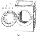
- FIG. 1 is a schematic assembly view of a door assembly of a drum washing machine of the present disclosure
- FIG. 2 is a schematic view showing an overall structure of a door assembly of a drum washing machine of the present disclosure
- FIG. 3 is a schematic view showing an internal structure of a door assembly of a drum washing machine of the present disclosure, in which an installation assembly of the door assembly is illustrated.
- the drum washing machine includes a machine body 1 and a door assembly 2 pivotally connected to a front side of the machine body 1. According to the orientation of FIG.
- a left side of the door assembly 2 is pivotally connected to the machine body 1 via a hinge 3
- a door hook 4 is installed on a right side of the door assembly 2
- the machine body 1 is correspondingly provided with a door lock 5 that cooperates with the door hook 4.
- a door opening direction of the door assembly 2 is as follows: taking a pivot axis of the hinge 3 as a rotation axis, the door assembly 2 is rotated around the rotation axis in a direction away from the door lock 5 (that is, the door assembly 2 in FIG. 1 is rotated from right to left in a clockwise direction), and the above-mentioned rotating direction is the initial door opening direction of the door assembly 2.
- the door assembly 2 specifically includes a ring-shaped outer frame 21, a ring-shaped inner frame 22, and a disc-shaped observation window 23 disposed between the outer frame 21 and the inner frame 22.
- a ring-shaped reinforcement structure 24 is disposed on an inner edge of the inner frame 22, and an installation assembly 25 is also disposed between the outer frame 21 and the inner frame 22.
- the reinforcement structure 24 serves to enhance the strength of the inner frame 22, and the installation assembly 25 is disposed between the outer frame 21 and the inner frame 22 by being fixed to the reinforcement structure 24.
- the installation assembly 25 is configured to enable the observation window 23 to be rotatably sandwiched between the outer frame 21 and the inner frame 22. In other words, the observation window 23 can rotate relative to the inner frame 22 and the outer frame 21 when it is installed between the inner frame 22 and the outer frame 21 through the installation assembly 25
- the observation window 23 gradually protrudes inward from top to bottom, that is, the largest raised portion of the observation window 23 is located on a lower side of the door assembly 2.
- the door assembly 2 is detached from the machine body 1 and rotated by 180° as a whole, the right side of the door assembly 2 changes from the door hook 4 to the hinge 3.
- the rotated door assembly 2 is reinstalled to the machine body 1.
- the right side of the door assembly 2 is pivotally connected to the machine body 1, the door opening direction of the door assembly 2 is opposite to its initial door opening direction, and the largest raised portion of the observation window 23 is located on the upper side of the door assembly 2.
- the observation window 23 between the outer frame 21 and the inner frame 22 is separately rotated by 180° again, so that the largest raised portion of the observation window 23 moves back to the lower side of the door assembly 2 to meet the spraying requirements of the drum washing machine. Till now, the steps of switching the door opening direction of the door assembly 2 are all completed.
- the installation orientation of the observation window 23 on the door assembly 2 can be adjusted without detaching the observation window 23 from the space between the outer window 21 and the inner frame 22, thereby saving the disassembly and assembly time of the door assembly 2 and simplifying the operation process when the user switches the door opening direction of the door assembly 2.
- the reinforcement structure 24 may also be disposed on an inner edge of the outer frame 21.
- the reinforcement structure 24 may be directly omitted, and the installation assembly 25 may be directly disposed on an inner side of the outer frame 21 or an outer side of the inner frame 22. That is, whether the reinforcement structure 24 needs to be disposed and the specific position of disposing the reinforcement structure 24 or the installation assembly 25 may be determined according to the actual strengths of the outer frame 21 and the inner frame 22.
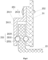
- FIG. 4 is a cross-sectional view taken along direction A-A in FIG. 3 .
- the inner side of the reinforcement structure 24 is fixed to the inner edge of the inner frame 22, and the installation assembly 25 includes a plurality of fixing members 251 evenly distributed in a radial direction of the observation window 23 and fixed to an outside ring surface of the reinforcement structure 24.
- each fixing member 251 is provided with an installation groove 2511, and opening directions of the installation grooves 2511 each face the edge of the observation window 23, so that the edge of the observation window 23 is rotatably accommodated in the installation grooves 2511.
- the fixing member 251 includes a sheet-like first portion 2512 and a Z-shaped sheet-like second portion 2513 fixed to an outer side of the first portion 2512.
- An inner side of the first portion 2512 is fixed to the reinforcement structure 24, and an inner side of an upper end of the Z-shaped sheet-like second portion 2513 is fixed to the first portion 2512, so that the installation groove 2511 is formed between a lower end of the second portion 2513 and the first portion 2512, and the installation groove 2511 can be formed on the fixing member 251 in the form of a U-shaped groove.
- the first portion 2512 and the second portion 2513 are detachably connected.
- a fastener such as a screw 252 passes through the second portion 2513 and the first portion 2512 in sequence and is threaded to the reinforcement structure 24, thereby fixing the first portion 2512 and the second portion 2513 of the fixing member 251.
- the installation assembly 25 further includes guide assemblies 253 disposed in the installation grooves 2511, and the observation window 23 rotates in the installation grooves 2511 through the guide assemblies 253.
- the guide assembly 253 includes rolling members 2531 in the form of a ball, limiting grooves 2532 disposed on an inner side of a groove wall of the installation groove 2511, and annular guide grooves 2533 disposed on the edge of the observation window 23. According to the orientation of FIG.
- left-side portions of the rolling members 2531 are rotatably accommodated in the arc-shaped pit-like limiting grooves 2532, and right-side portions of the rolling members 2531 are rotatably embedded in the annular guide grooves 2533, so that the observation window 23 are rotatably abutted against the inner side of the groove wall of the installation grooves 2511 through the rolling members 2531.
- the inner side and outer side of the edge of the observation window 23 are respectively provided with the annular guide groove 2533, the side walls on both sides of the installation groove 2511 are respectively provided with the limiting groove 2532, and the rolling member 2531 is embedded between the inner side of the edge of the observation window 23 and the groove wall of the installation groove 2511 on the corresponding side as well as between the outer side of the edge of the observation window 23 and the groove wall of the installation groove 2511 on the corresponding side, so that both the inner and outer sides of the edge of the observation window 23 can be movably abutted against the groove walls of the installation groove 2511 through the balls, which not only increases the flexibility of the rotation of the observation window 23, but also prevents the observation window 23 from shaking between the inner frame 22 and the outer frame 21.
- At least one group of locking assembly 26 is further disposed between the outer frame 21 and the inner frame 22, which is configured to limit rotation of the observation window 23 in the installation grooves 2511 and to avoid accidental change of the installation orientation of the observation window 23 after rotative adjustment.
- the locking assembly 26 includes a limiting post 261, a guide groove 262 disposed on an outer side of the reinforcement structure 24 in the radial direction of the observation window 23, and a capture hole disposed in the observation window 23.
- a protruding end 264 also protrudes from the limiting post 261 in a direction perpendicular to the limiting post 261, and a slide groove 265 is formed in the reinforcement structure 24, which penetrates through the reinforcement structure 24 in an opening direction of the guide groove 262. In an assembled state, the protruding end 264 protrudes into the slide groove 265 and passes through the slide groove 265 to reach the outside of the door assembly 2.
- the user When the user needs to adjust the installation orientation of the observation window 23 (that is, the observation window 23 is allowed to rotate), the user can hold the protruding end 264 and toggle the protruding end 264 to slide away from the observation window 23 in an opening direction of the slide groove 265.
- the limiting post 261 exits the capture hole and moves into the guide groove 262, and the elastic member 263 is in a compressed state.
- the protruding end 264 is released, and the elastic member 263 is changed from the compressed state to an expanded state, so that the limiting post 261 is inserted into the capture hole again when pushed by the elastic member 263 to lock the observation window 23.
- the position of disposing each capture hole in the observation window 23 needs to be specifically set according to the actual rotation requirement of the observation window 23 (such as the commonly used rotation angle of the observation window 23). For example, when the observation window 23 needs to be rotated by 180°, the number of the locking assemblies 26 in FIG. 3 is two and the two locking assemblies 26 are respectively disposed at positions directly above and below the observation window 23.
- the drum washing machine of the present disclosure includes the door assembly 2.
- the door assembly 2 specifically includes the outer frame 21, the inner frame 22, and the observation window 23 disposed between the outer frame 21 and the inner frame 22, and the installation assembly 25 and the locking assembly 26 are further disposed between the outer frame 21 and the inner frame 22.
- the observation window 23 is rotatably sandwiched between the outer frame 21 and the inner frame 22 by means of the installation assembly 25, and the locking assembly 26 is configured to limit the rotation of the observation window 23 so that the installation orientation of the observation window 23 can be reliably maintained after the observation window 23 is rotated.
- the observation window 23 can be rotated separately relative to the outer frame 21 and the inner frame 22, thereby solving the problem that the user further needs to disassemble, rotate and assemble the observation window 23 when switching the door opening direction of the door assembly 2, which saves the overall operation time when the user switches the door opening direction of the door assembly 2.
Landscapes
- Engineering & Computer Science (AREA)
- Textile Engineering (AREA)
- Main Body Construction Of Washing Machines And Laundry Dryers (AREA)
Abstract
Description
- The present disclosure belongs to the technical field of laundry treatment device, and specifically provides a door assembly of a laundry treatment device, and a laundry treatment device.
- A front-loading drum washing machine includes a machine body and a machine door disposed on a front side of the machine body. Before the drum washing machine performs a washing operation, the user needs to open the door on the front side of the drum washing machine to put laundry in. Specifically, the door includes an observation window with a raised structure formed on an inner side, so only after a door opening angle of the machine door reaches a certain degree (such as at least 140°) can the machine door be fully opened to meet the user's need for picking up and placing laundry. However, since there may be obstacles near the drum washing machine that affect the opening of the machine door, such as a wall of a room or other household appliances placed around the drum washing machine, a placement environment of the drum washing machine is restricted.
- At present, the drum washing machine is typically provided with a machine door, for which a door opening direction can be switched. When there is an obstacle on a side of the drum washing machine, which affects a normal opening of the machine door, the user can detach the machine door from the machine body, rotate it by 180° and then reinstall it on the machine body so that the machine door can be switched from being opened by rotating in a direction approaching the obstacle to being opened by rotating in a direction away from the obstacle. As such, a normal use of the drum washing machine is ensured without moving the drum washing machine. However, the disadvantage of the above method is that some of the observation windows are provided with the above raised structure in an asymmetric manner. After the machine door is rotated by 180°, the observation window is inverted due to the rotation, so that the position of the raised structure of the observation window is changed from being away from a spraying device in the drum washing machine to being close to the spraying device, thereby affecting a spraying effect of the drum washing machine. In this case, in order to enable the raised structure of the observation window to be located away from the spraying structure, the user also needs to detach the observation window from the machine door and rotate it by 180° before assembling it onto the machine door, which takes a lot of time for assembly and makes the step of switching the opening direction of the machine door cumbersome.
- Accordingly, there is a need in the art for a new door assembly of a laundry treatment device as well as a laundry treatment device to solve the above problems.
- In order to solve the above problems in the related art, that is, to solve the problems of cumbersome assembling steps and long installation time when the door opening direction is switched for the machine doors of the existing drum washing machines, the present disclosure provides a door assembly of a laundry treatment device, wherein the door assembly includes an outer frame, an inner frame, and an observation window disposed between the outer frame and the inner frame, and wherein an installation assembly is disposed between the outer frame and the inner frame, and the installation assembly is configured to enable the observation window to be rotatably sandwiched between the outer frame and the inner frame.
- In a preferred technical solution of the above door assembly of the laundry treatment device, the installation assembly includes at least one fixing member disposed on an inner edge of the outer frame or an inner edge of the inner frame, wherein the fixing member is formed with an installation groove, and an edge of the observation window is rotatably accommodated in the installation groove.
- In a preferred technical solution of the above door assembly of the laundry treatment device, the installation assembly further includes a guide assembly disposed in the installation groove, and the observation window is rotated in the installation groove by means of the guide assembly.
- In a preferred technical solution of the above door assembly of the laundry treatment device, the guide assembly includes: rolling members; limiting grooves disposed on an inner side of a groove wall of the installation groove, the rolling members being rotatably accommodated in the limiting grooves; and annular guide grooves disposed on the edge of the observation window, the rolling members also being capable of rolling in the annular guide grooves.
- In a preferred technical solution of the above door assembly of the laundry treatment device, the rolling members are balls, and the limiting grooves are arc-shaped concave grooves disposed on the inner side of the groove wall.
- In a preferred technical solution of the above door assembly of the laundry treatment device, an inner side and an outer side of the edge of the observation window are respectively provided with the annular guide groove, the groove walls on both sides of the installation groove are respectively provided with the arc-shaped concave groove, and the ball is embedded between the inner side of the observation window and the groove wall on the corresponding side as well as between the outer side of the observation window and the groove wall on the corresponding side.
- In a preferred technical solution of the above door assembly of the laundry treatment device, a ring-shaped reinforcement structure is fixed to the inner frame, and the fixing member is disposed on the reinforcement structure.
- In a preferred technical solution of the above door assembly of the laundry treatment device, a locking assembly is further disposed between the outer frame and the inner frame, and the locking assembly includes: a limiting post disposed in a radial direction of the observation window; a guide groove disposed in the reinforcement member; and a capture hole disposed in the observation window, wherein one end of the limiting post is fixed into the guide groove in an elastic connection manner, and the other end of the limiting post is inserted into or retracted from the capture hole in a retractable manner.
- In a preferred technical solution of the above door assembly of the laundry treatment device, the limiting post is further provided with a protruding end, the reinforcement structure is provided with a slide groove, and the protruding end is capable of protruding into the slide groove and sliding along the slide groove.
- A laundry treatment device is further provided, which includes any above described door assembly.
- Those skilled in the art can understand that in the technical solutions of the present disclosure, the door assembly of the laundry treatment device of the present disclosure includes an outer frame, an inner frame, and an observation window disposed between the outer frame and the inner frame, and an installation assembly is disposed between the outer frame and the inner frame, wherein the observation window can be rotatably sandwiched between the outer frame and the inner frame through the installation assembly; that is, the observation window is capable of rotating relative to the inner frame and the outer frame without deviating from the space between the inner frame and the outer frame. Taking the machine door of the drum washing machine as an example, when the machine door is detached, rotated by 180° and then reinstalled onto the drum washing machine to switch the door opening direction, even if the observation window of the machine door has an asymmetric raised structure, there is no need for the user to detach the observation window from the machine door and adjust an installation orientation of the observation window on the machine door. It is only required to directly rotate the observation window assembled between the outer frame and the inner frame so that the raised structure can be adjusted to a position far away from the spraying position of the drum washing machine. In the process of switching the door opening direction of the machine door, the steps of detaching and reinstalling the observation window are omitted, and the operation time when the user switches the door opening direction of the machine door is shortened.
- Preferred embodiments of the present disclosure will be described below with reference to the drawings and in conjunction with an example in which the laundry treatment device is a washing machine. In the drawings:
-
FIG. 1 is a schematic assembly view of a door assembly of a drum washing machine of the present disclosure; -
FIG. 2 is a schematic view showing an overall structure of a door assembly of a drum washing machine of the present disclosure; -
FIG. 3 is a schematic view showing an internal structure of a door assembly of a drum washing machine of the present disclosure, in which an installation assembly of the door assembly is illustrated. -
FIG. 4 is a cross-sectional view taken along line A-A inFIG. 3 ; and -
FIG. 5 is a cross-sectional view taken along line B-B inFIG. 3 . - In the drawings: 1: machine body; 2: door assembly; 21: outer frame; 22: inner frame; 23: observation window; 24: reinforcement structure; 25: installation assembly; 251: fixing member; 2511: installation groove; 2512: first portion; 2513: second portion; 252: screw; 253: guide assembly; 2531: rolling member; 2532: limiting groove; 2533: annular guide groove; 26: locking assembly; 261: limiting post; 262: guide groove; 263: elastic member; 264: protruding end; 265: slide groove; 3: hinge; 4: door hook; 5: door lock.
- First, it should be understood by those skilled in the art that these embodiments are only used to explain the technical principles of the present disclosure, and are not intended to limit the scope of protection of the present disclosure. Those skilled in the art may make an adjustment to the present disclosure as required so as to be adapted to specific application occasions. For example, although the door assembly of the present disclosure is described in conjunction with a drum washing machine, it is not limiting, and it is obvious that in addition to the drum washing machine, the door assembly of the present disclosure is also applicable to other laundry treatment devices with an observation window having a similar need for adjusting installation orientation.
- It should be noted that in the description of the present disclosure, directional or positional relationships indicated by terms such as "left", "right", "inner" and "outer" are based on the directions or positional relationships shown in the drawings. They are merely used for the convenience of description, and do not indicate or imply that the device or element involved must have a specific orientation, or be configured or operated in a specific orientation, and therefore they should not be construed as limiting the present disclosure.
- In addition, it should also be noted that in the description of the present disclosure, unless otherwise clearly specified and defined, terms "install", "connect" and "connection" should be understood in a broad sense; for example, the connection may be a fixed connection, or may also be a detachable connection, or an integral connection; it may be a mechanical connection, or an electrical connection; it may be a direct connection, or an indirect connection implemented through an intermediate medium, or it may be an internal communication between two elements. For those skilled in the art, the specific meaning of the above terms in the present disclosure can be understood according to specific situations.
- Reference is first made to
FIGS. 1 ,2 and3 , whereinFIG. 1 is a schematic assembly view of a door assembly of a drum washing machine of the present disclosure,FIG. 2 is a schematic view showing an overall structure of a door assembly of a drum washing machine of the present disclosure, andFIG. 3 is a schematic view showing an internal structure of a door assembly of a drum washing machine of the present disclosure, in which an installation assembly of the door assembly is illustrated. As shown inFIGS. 1 ,2 and3 , the drum washing machine includes amachine body 1 and adoor assembly 2 pivotally connected to a front side of themachine body 1. According to the orientation ofFIG. 1 , a left side of thedoor assembly 2 is pivotally connected to themachine body 1 via ahinge 3, adoor hook 4 is installed on a right side of thedoor assembly 2, and themachine body 1 is correspondingly provided with adoor lock 5 that cooperates with thedoor hook 4. When thedoor assembly 2 is in a closed state, thedoor assembly 2 is locked to themachine body 1 through the cooperation of thedoor hook 4 and thedoor lock 5. In this case, a door opening direction of thedoor assembly 2 is as follows: taking a pivot axis of thehinge 3 as a rotation axis, thedoor assembly 2 is rotated around the rotation axis in a direction away from the door lock 5 (that is, thedoor assembly 2 inFIG. 1 is rotated from right to left in a clockwise direction), and the above-mentioned rotating direction is the initial door opening direction of thedoor assembly 2. - The
door assembly 2 specifically includes a ring-shapedouter frame 21, a ring-shapedinner frame 22, and a disc-shaped observation window 23 disposed between theouter frame 21 and theinner frame 22. A ring-shaped reinforcement structure 24 is disposed on an inner edge of theinner frame 22, and aninstallation assembly 25 is also disposed between theouter frame 21 and theinner frame 22. Thereinforcement structure 24 serves to enhance the strength of theinner frame 22, and theinstallation assembly 25 is disposed between theouter frame 21 and theinner frame 22 by being fixed to thereinforcement structure 24. Moreover, theinstallation assembly 25 is configured to enable theobservation window 23 to be rotatably sandwiched between theouter frame 21 and theinner frame 22. In other words, theobservation window 23 can rotate relative to theinner frame 22 and theouter frame 21 when it is installed between theinner frame 22 and theouter frame 21 through theinstallation assembly 25 - When the door opening direction of the
door assembly 2 is the initial door opening direction, theobservation window 23 gradually protrudes inward from top to bottom, that is, the largest raised portion of theobservation window 23 is located on a lower side of thedoor assembly 2. When thedoor assembly 2 is detached from themachine body 1 and rotated by 180° as a whole, the right side of thedoor assembly 2 changes from thedoor hook 4 to thehinge 3. After the fixed positions of thedoor lock 5 and thehinge 3 on themachine body 1 are interchanged, the rotateddoor assembly 2 is reinstalled to themachine body 1. At this point, the right side of thedoor assembly 2 is pivotally connected to themachine body 1, the door opening direction of thedoor assembly 2 is opposite to its initial door opening direction, and the largest raised portion of theobservation window 23 is located on the upper side of thedoor assembly 2. In order to avoid that the displacement of the largest raised portion of theobservation window 23 affects a spraying effect of the drum washing machine, finally theobservation window 23 between theouter frame 21 and theinner frame 22 is separately rotated by 180° again, so that the largest raised portion of theobservation window 23 moves back to the lower side of thedoor assembly 2 to meet the spraying requirements of the drum washing machine. Till now, the steps of switching the door opening direction of thedoor assembly 2 are all completed. - With the arrangement of the
installation assembly 25, the installation orientation of theobservation window 23 on thedoor assembly 2 can be adjusted without detaching theobservation window 23 from the space between theouter window 21 and theinner frame 22, thereby saving the disassembly and assembly time of thedoor assembly 2 and simplifying the operation process when the user switches the door opening direction of thedoor assembly 2. - It should be noted that in the case where the strengths of the
outer frame 21 and theinner frame 22 are sufficiently large, in addition to disposing thereinforcement structure 24 on the inner edge of theinner frame 22, thereinforcement structure 24 may also be disposed on an inner edge of theouter frame 21. Alternatively, thereinforcement structure 24 may be directly omitted, and theinstallation assembly 25 may be directly disposed on an inner side of theouter frame 21 or an outer side of theinner frame 22. That is, whether thereinforcement structure 24 needs to be disposed and the specific position of disposing thereinforcement structure 24 or theinstallation assembly 25 may be determined according to the actual strengths of theouter frame 21 and theinner frame 22. - Next, reference is made to
FIG. 4 and continued reference is made toFIG. 3 , whereinFIG. 4 is a cross-sectional view taken along direction A-A inFIG. 3 . As shown inFIGS. 3 and4 , as a preferred embodiment, the inner side of thereinforcement structure 24 is fixed to the inner edge of theinner frame 22, and theinstallation assembly 25 includes a plurality of fixingmembers 251 evenly distributed in a radial direction of theobservation window 23 and fixed to an outside ring surface of thereinforcement structure 24. Moreover, each fixingmember 251 is provided with aninstallation groove 2511, and opening directions of theinstallation grooves 2511 each face the edge of theobservation window 23, so that the edge of theobservation window 23 is rotatably accommodated in theinstallation grooves 2511. Specifically, according to the orientation ofFIG. 4 , the fixingmember 251 includes a sheet-likefirst portion 2512 and a Z-shaped sheet-likesecond portion 2513 fixed to an outer side of thefirst portion 2512. An inner side of thefirst portion 2512 is fixed to thereinforcement structure 24, and an inner side of an upper end of the Z-shaped sheet-likesecond portion 2513 is fixed to thefirst portion 2512, so that theinstallation groove 2511 is formed between a lower end of thesecond portion 2513 and thefirst portion 2512, and theinstallation groove 2511 can be formed on the fixingmember 251 in the form of a U-shaped groove. Of course, in order to insert theobservation window 23 into theinstallation grooves 2511 or remove it from theinstallation grooves 2511, thefirst portion 2512 and thesecond portion 2513 are detachably connected. For example, a fastener such as ascrew 252 passes through thesecond portion 2513 and thefirst portion 2512 in sequence and is threaded to thereinforcement structure 24, thereby fixing thefirst portion 2512 and thesecond portion 2513 of the fixingmember 251. - With continued reference to
FIGS. 3 and4 , in order to prevent theobservation window 23 from being worn due to friction between theinner frame 22 and theouter frame 21 during the rotation, and to prevent theobservation window 23 from jumping in the radial direction of theouter frame 21 or theinner frame 22, preferably, theinstallation assembly 25 further includesguide assemblies 253 disposed in theinstallation grooves 2511, and theobservation window 23 rotates in theinstallation grooves 2511 through theguide assemblies 253. Specifically, theguide assembly 253 includes rollingmembers 2531 in the form of a ball, limitinggrooves 2532 disposed on an inner side of a groove wall of theinstallation groove 2511, andannular guide grooves 2533 disposed on the edge of theobservation window 23. According to the orientation ofFIG. 4 , left-side portions of the rollingmembers 2531 are rotatably accommodated in the arc-shaped pit-like limitinggrooves 2532, and right-side portions of the rollingmembers 2531 are rotatably embedded in theannular guide grooves 2533, so that theobservation window 23 are rotatably abutted against the inner side of the groove wall of theinstallation grooves 2511 through the rollingmembers 2531. More preferably, the inner side and outer side of the edge of theobservation window 23 are respectively provided with theannular guide groove 2533, the side walls on both sides of theinstallation groove 2511 are respectively provided with the limitinggroove 2532, and the rollingmember 2531 is embedded between the inner side of the edge of theobservation window 23 and the groove wall of theinstallation groove 2511 on the corresponding side as well as between the outer side of the edge of theobservation window 23 and the groove wall of theinstallation groove 2511 on the corresponding side, so that both the inner and outer sides of the edge of theobservation window 23 can be movably abutted against the groove walls of theinstallation groove 2511 through the balls, which not only increases the flexibility of the rotation of theobservation window 23, but also prevents theobservation window 23 from shaking between theinner frame 22 and theouter frame 21. - Since the body of the drum washing machine will slightly vibrate when the drum washing machine is working, in order to avoid accidental rotation of the
observation window 23 when the drum washing machine is working or thedoor assembly 2 is collided, at least one group of lockingassembly 26 is further disposed between theouter frame 21 and theinner frame 22, which is configured to limit rotation of theobservation window 23 in theinstallation grooves 2511 and to avoid accidental change of the installation orientation of theobservation window 23 after rotative adjustment. Specifically, the lockingassembly 26 includes a limitingpost 261, aguide groove 262 disposed on an outer side of thereinforcement structure 24 in the radial direction of theobservation window 23, and a capture hole disposed in theobservation window 23. One end of the limitingpost 261 is fixed into theguide groove 262 through an elastic member 263 (such as a spring), and the other end of the limitingpost 261 is inserted into or retracted from the capture hole in a retractable manner, so as to restrict or allow rotation of theobservation window 23 in theinstallation grooves 2511. In addition, aprotruding end 264 also protrudes from the limitingpost 261 in a direction perpendicular to the limitingpost 261, and aslide groove 265 is formed in thereinforcement structure 24, which penetrates through thereinforcement structure 24 in an opening direction of theguide groove 262. In an assembled state, theprotruding end 264 protrudes into theslide groove 265 and passes through theslide groove 265 to reach the outside of thedoor assembly 2. - When the user needs to adjust the installation orientation of the observation window 23 (that is, the
observation window 23 is allowed to rotate), the user can hold theprotruding end 264 and toggle theprotruding end 264 to slide away from theobservation window 23 in an opening direction of theslide groove 265. The limitingpost 261 exits the capture hole and moves into theguide groove 262, and theelastic member 263 is in a compressed state. After theobservation window 23 is rotated and the adjustment is completed, theprotruding end 264 is released, and theelastic member 263 is changed from the compressed state to an expanded state, so that the limitingpost 261 is inserted into the capture hole again when pushed by theelastic member 263 to lock theobservation window 23. The position of disposing each capture hole in theobservation window 23 needs to be specifically set according to the actual rotation requirement of the observation window 23 (such as the commonly used rotation angle of the observation window 23). For example, when theobservation window 23 needs to be rotated by 180°, the number of thelocking assemblies 26 inFIG. 3 is two and the twolocking assemblies 26 are respectively disposed at positions directly above and below theobservation window 23. - In summary, the drum washing machine of the present disclosure includes the
door assembly 2. Thedoor assembly 2 specifically includes theouter frame 21, theinner frame 22, and theobservation window 23 disposed between theouter frame 21 and theinner frame 22, and theinstallation assembly 25 and the lockingassembly 26 are further disposed between theouter frame 21 and theinner frame 22. Theobservation window 23 is rotatably sandwiched between theouter frame 21 and theinner frame 22 by means of theinstallation assembly 25, and the lockingassembly 26 is configured to limit the rotation of theobservation window 23 so that the installation orientation of theobservation window 23 can be reliably maintained after theobservation window 23 is rotated. With the above arrangement, theobservation window 23 can be rotated separately relative to theouter frame 21 and theinner frame 22, thereby solving the problem that the user further needs to disassemble, rotate and assemble theobservation window 23 when switching the door opening direction of thedoor assembly 2, which saves the overall operation time when the user switches the door opening direction of thedoor assembly 2. - Hitherto, the technical solutions of the present disclosure have been described in conjunction with the preferred embodiments shown in the accompanying drawings, but it is easily understood by those skilled in the art that the scope of protection of the present disclosure is obviously not limited to these specific embodiments. Without departing from the principle of the present disclosure, those skilled in the art can make equivalent changes or replacements to relevant technical features, and the technical solutions after these changes or replacements will fall within the scope of protection of the present disclosure.
Claims (10)
- A door assembly of a laundry treatment device, comprising an outer frame, an inner frame, and an observation window disposed between the outer frame and the inner frame,
wherein an installation assembly is disposed between the outer frame and the inner frame, and the installation assembly is configured to enable the observation window to be rotatably sandwiched between the outer frame and the inner frame. - The door assembly of the laundry treatment device according to claim 1, wherein the installation assembly comprises at least one fixing member disposed on an inner edge of the outer frame or an inner edge of the inner frame, the fixing member is formed with an installation groove, and an edge of the observation window is rotatably accommodated in the installation groove.
- The door assembly of the laundry treatment device according to claim 2, wherein the installation assembly further comprises a guide assembly disposed in the installation groove, and the observation window is rotated in the installation groove by means of the guide assembly.
- The door assembly of the laundry treatment device according to claim 3, wherein the guide assembly comprises:rolling members;limiting grooves disposed on an inner side of a groove wall of the installation groove, the rolling members being rotatably accommodated in the limiting grooves; andannular guide grooves disposed on the edge of the observation window, the rolling members also being capable of rolling in the annular guide grooves.
- The door assembly of the laundry treatment device according to claim 4, wherein the rolling members are balls, and the limiting grooves are arc-shaped concave grooves disposed on the inner side of the groove wall.
- The door assembly of the laundry treatment device according to claim 5, wherein an inner side and an outer side of the edge of the observation window are respectively provided with the annular guide groove, the groove walls on both sides of the installation groove are respectively provided with the arc-shaped concave groove, and the ball is embedded between the inner side of the observation window and the groove wall on the corresponding side as well as between the outer side of the observation window and the groove wall on the corresponding side.
- The door assembly of the laundry treatment device according to any one of claims 2 to 6, wherein a ring-shaped reinforcement structure is fixed to the inner frame, and the fixing member is disposed on the reinforcement structure.
- The door assembly of the laundry treatment device according to claim 7, wherein a locking assembly is further disposed between the outer frame and the inner frame, and the locking assembly comprises:a limiting post disposed in a radial direction of the observation window;a guide groove disposed in the reinforcement member; anda capture hole disposed in the observation window,wherein one end of the limiting post is fixed into the guide groove in an elastic connection manner, and the other end of the limiting post is inserted into or retracted from the capture hole in a retractable manner.
- The door assembly of the laundry treatment device according to claim 8, wherein the limiting post is further provided with a protruding end, the reinforcement structure is provided with a slide groove, and the protruding end is capable of protruding into the slide groove and sliding along the slide groove.
- A laundry treatment device, comprising the door assembly according to any one of claims 1 to 9.
Applications Claiming Priority (2)
| Application Number | Priority Date | Filing Date | Title |
|---|---|---|---|
| CN201810035327.0A CN110042624B (en) | 2018-01-15 | 2018-01-15 | Door assembly of clothes treatment equipment and clothes treatment equipment |
| PCT/CN2018/122415 WO2019137177A1 (en) | 2018-01-15 | 2018-12-20 | Door assembly of laundry treatment device and laundry treatment device |
Publications (3)
| Publication Number | Publication Date |
|---|---|
| EP3741905A1 true EP3741905A1 (en) | 2020-11-25 |
| EP3741905A4 EP3741905A4 (en) | 2021-01-06 |
| EP3741905B1 EP3741905B1 (en) | 2022-09-07 |
Family
ID=67218492
Family Applications (1)
| Application Number | Title | Priority Date | Filing Date |
|---|---|---|---|
| EP18900206.6A Active EP3741905B1 (en) | 2018-01-15 | 2018-12-20 | Door assembly of laundry treatment device and laundry treatment device |
Country Status (4)
| Country | Link |
|---|---|
| US (1) | US11920284B2 (en) |
| EP (1) | EP3741905B1 (en) |
| CN (1) | CN110042624B (en) |
| WO (1) | WO2019137177A1 (en) |
Families Citing this family (5)
| Publication number | Priority date | Publication date | Assignee | Title |
|---|---|---|---|---|
| USD878687S1 (en) * | 2017-05-31 | 2020-03-17 | Whirlpool Corporation | Fabric care appliance |
| US11210474B2 (en) | 2019-08-15 | 2021-12-28 | Advanced New Technologies Co., Ltd. | Language processing using a neural network |
| CN115679653A (en) * | 2021-07-21 | 2023-02-03 | 青岛海尔洗涤电器有限公司 | Clothes processing device and door body thereof |
| USD1113000S1 (en) * | 2023-08-30 | 2026-02-10 | Lg Electronics Inc. | Electric washing machine |
| USD1107347S1 (en) * | 2024-10-25 | 2025-12-23 | Iris Ohyama Inc. | Washing machine |
Family Cites Families (16)
| Publication number | Priority date | Publication date | Assignee | Title |
|---|---|---|---|---|
| WO2003004754A1 (en) * | 2001-07-05 | 2003-01-16 | Arçelik, A. S. | Washing machine door |
| KR20050022092A (en) * | 2003-08-26 | 2005-03-07 | 엘지전자 주식회사 | Glass cover of door for drum type washer |
| CN101074532A (en) * | 2006-05-19 | 2007-11-21 | 南京乐金熊猫电器有限公司 | Drum washer door |
| US8661860B2 (en) * | 2009-07-31 | 2014-03-04 | Bsh Home Appliances Corporation | Door bowl for a household appliance door |
| US9212449B2 (en) * | 2010-08-31 | 2015-12-15 | Bsh Home Appliances Corporation | Structural door bowl for a household appliance door |
| CN202865629U (en) * | 2012-09-04 | 2013-04-10 | 无锡小天鹅通用电器有限公司 | Cabinet front cover system of roller washing machine |
| CN202898808U (en) | 2012-10-16 | 2013-04-24 | 青岛澳柯玛洗衣机有限公司 | Observation window for drum washing machine |
| PL2843107T3 (en) * | 2013-08-30 | 2023-05-02 | Electrolux Appliances Aktiebolag | Laundry treatment device with a door assembly |
| PL2843105T3 (en) * | 2013-08-30 | 2017-07-31 | Electrolux Appliances Aktiebolag | A door assembly for a laundry treatment device and method of operation |
| EP3034677B1 (en) | 2014-12-19 | 2021-02-17 | Electrolux Appliances Aktiebolag | Door assembly for laundry treatment apparatus |
| CN106149301B (en) * | 2015-03-31 | 2020-05-05 | 青岛海尔滚筒洗衣机有限公司 | Observation window and door rotatable front-loading washing machine |
| CN204715082U (en) * | 2015-06-18 | 2015-10-21 | 常山优博特机电科技有限公司 | A kind of have the roller washing machine that inside and outside can overturn the door of washing machine of fluoroscopic observation window |
| CN105177911B (en) * | 2015-09-02 | 2020-03-24 | 无锡小天鹅通用电器有限公司 | drum washing machine |
| CN106906622B (en) * | 2015-12-22 | 2023-10-27 | 无锡小天鹅电器有限公司 | Door body assembly of drum washing machine and drum washing machine with door body assembly |
| CN205669131U (en) * | 2016-06-03 | 2016-11-02 | 康红宾 | Roller washing machine observation window pad |
| CN206127678U (en) * | 2016-07-04 | 2017-04-26 | 青岛海尔洗涤电器有限公司 | Washing machine door body and washing machine of asymmetric glass window |
-
2018
- 2018-01-15 CN CN201810035327.0A patent/CN110042624B/en active Active
- 2018-12-20 EP EP18900206.6A patent/EP3741905B1/en active Active
- 2018-12-20 US US16/962,039 patent/US11920284B2/en active Active
- 2018-12-20 WO PCT/CN2018/122415 patent/WO2019137177A1/en not_active Ceased
Also Published As
| Publication number | Publication date |
|---|---|
| EP3741905A4 (en) | 2021-01-06 |
| CN110042624B (en) | 2021-12-03 |
| US20200399818A1 (en) | 2020-12-24 |
| CN110042624A (en) | 2019-07-23 |
| WO2019137177A1 (en) | 2019-07-18 |
| EP3741905B1 (en) | 2022-09-07 |
| US11920284B2 (en) | 2024-03-05 |
Similar Documents
| Publication | Publication Date | Title |
|---|---|---|
| US11920284B2 (en) | Door assembly of laundry treatment device and laundry treatment device | |
| JP6062164B2 (en) | Hinge device | |
| US6564428B2 (en) | Compound hinge | |
| EP3786400A1 (en) | Door closer and refrigerator comprising same | |
| US5582442A (en) | Latch assembly and manufacturing and painting processes | |
| CN207391826U (en) | The latch assembly of top-opening type clothes treatment device and its inner cylinder and inside drum cover | |
| CN106801554A (en) | A kind of door of refrigerator body hinge component and the refrigerator with it | |
| CN109216096B (en) | Interlocking structure for grounding switch and lower door, switch cabinet and operation method thereof | |
| KR200488839Y1 (en) | The apparatus for opening and closing cabinet door | |
| KR101880786B1 (en) | Door locking device, particularly for electric household appliances | |
| KR102623990B1 (en) | Left and Right Switching Assembly for Cassette Handle | |
| KR101323599B1 (en) | Hinge device | |
| CN208231836U (en) | A kind of robot head rotational locking device | |
| KR101862511B1 (en) | Lever for windows and doors with locking function | |
| CN201891335U (en) | Door closing stop device | |
| CN104121749A (en) | Door of refrigerator and refrigerator | |
| KR200355677Y1 (en) | Window frame having ventilating-hole | |
| CN211598160U (en) | Internal and external automatic reset door hinge | |
| CN203669626U (en) | Box door assembly structure | |
| EP1022419B1 (en) | Compound hinge | |
| CN223164403U (en) | Hinge structure, hover door and refrigerator | |
| KR101467546B1 (en) | Window | |
| KR200345030Y1 (en) | safe door opening and closing movement | |
| KR101972849B1 (en) | Door keeper | |
| KR100634045B1 (en) | Two-way retractable hinge |
Legal Events
| Date | Code | Title | Description |
|---|---|---|---|
| STAA | Information on the status of an ep patent application or granted ep patent |
Free format text: STATUS: THE INTERNATIONAL PUBLICATION HAS BEEN MADE |
|
| PUAI | Public reference made under article 153(3) epc to a published international application that has entered the european phase |
Free format text: ORIGINAL CODE: 0009012 |
|
| STAA | Information on the status of an ep patent application or granted ep patent |
Free format text: STATUS: REQUEST FOR EXAMINATION WAS MADE |
|
| 17P | Request for examination filed |
Effective date: 20200817 |
|
| AK | Designated contracting states |
Kind code of ref document: A1 Designated state(s): AL AT BE BG CH CY CZ DE DK EE ES FI FR GB GR HR HU IE IS IT LI LT LU LV MC MK MT NL NO PL PT RO RS SE SI SK SM TR |
|
| AX | Request for extension of the european patent |
Extension state: BA ME |
|
| A4 | Supplementary search report drawn up and despatched |
Effective date: 20201204 |
|
| RIC1 | Information provided on ipc code assigned before grant |
Ipc: D06F 39/14 20060101AFI20201130BHEP Ipc: D06F 37/18 20060101ALI20201130BHEP Ipc: D06F 37/28 20060101ALI20201130BHEP |
|
| DAV | Request for validation of the european patent (deleted) | ||
| DAX | Request for extension of the european patent (deleted) | ||
| GRAP | Despatch of communication of intention to grant a patent |
Free format text: ORIGINAL CODE: EPIDOSNIGR1 |
|
| STAA | Information on the status of an ep patent application or granted ep patent |
Free format text: STATUS: GRANT OF PATENT IS INTENDED |
|
| RIC1 | Information provided on ipc code assigned before grant |
Ipc: D06F 39/14 20060101AFI20220314BHEP |
|
| INTG | Intention to grant announced |
Effective date: 20220408 |
|
| GRAS | Grant fee paid |
Free format text: ORIGINAL CODE: EPIDOSNIGR3 |
|
| GRAA | (expected) grant |
Free format text: ORIGINAL CODE: 0009210 |
|
| STAA | Information on the status of an ep patent application or granted ep patent |
Free format text: STATUS: THE PATENT HAS BEEN GRANTED |
|
| AK | Designated contracting states |
Kind code of ref document: B1 Designated state(s): AL AT BE BG CH CY CZ DE DK EE ES FI FR GB GR HR HU IE IS IT LI LT LU LV MC MK MT NL NO PL PT RO RS SE SI SK SM TR |
|
| REG | Reference to a national code |
Ref country code: GB Ref legal event code: FG4D |
|
| REG | Reference to a national code |
Ref country code: CH Ref legal event code: EP Ref country code: AT Ref legal event code: REF Ref document number: 1517120 Country of ref document: AT Kind code of ref document: T Effective date: 20220915 |
|
| REG | Reference to a national code |
Ref country code: IE Ref legal event code: FG4D |
|
| REG | Reference to a national code |
Ref country code: DE Ref legal event code: R096 Ref document number: 602018040518 Country of ref document: DE |
|
| REG | Reference to a national code |
Ref country code: LT Ref legal event code: MG9D |
|
| REG | Reference to a national code |
Ref country code: NL Ref legal event code: MP Effective date: 20220907 |
|
| PG25 | Lapsed in a contracting state [announced via postgrant information from national office to epo] |
Ref country code: SE Free format text: LAPSE BECAUSE OF FAILURE TO SUBMIT A TRANSLATION OF THE DESCRIPTION OR TO PAY THE FEE WITHIN THE PRESCRIBED TIME-LIMIT Effective date: 20220907 Ref country code: RS Free format text: LAPSE BECAUSE OF FAILURE TO SUBMIT A TRANSLATION OF THE DESCRIPTION OR TO PAY THE FEE WITHIN THE PRESCRIBED TIME-LIMIT Effective date: 20220907 Ref country code: NO Free format text: LAPSE BECAUSE OF FAILURE TO SUBMIT A TRANSLATION OF THE DESCRIPTION OR TO PAY THE FEE WITHIN THE PRESCRIBED TIME-LIMIT Effective date: 20221207 Ref country code: LV Free format text: LAPSE BECAUSE OF FAILURE TO SUBMIT A TRANSLATION OF THE DESCRIPTION OR TO PAY THE FEE WITHIN THE PRESCRIBED TIME-LIMIT Effective date: 20220907 Ref country code: LT Free format text: LAPSE BECAUSE OF FAILURE TO SUBMIT A TRANSLATION OF THE DESCRIPTION OR TO PAY THE FEE WITHIN THE PRESCRIBED TIME-LIMIT Effective date: 20220907 Ref country code: FI Free format text: LAPSE BECAUSE OF FAILURE TO SUBMIT A TRANSLATION OF THE DESCRIPTION OR TO PAY THE FEE WITHIN THE PRESCRIBED TIME-LIMIT Effective date: 20220907 |
|
| REG | Reference to a national code |
Ref country code: AT Ref legal event code: MK05 Ref document number: 1517120 Country of ref document: AT Kind code of ref document: T Effective date: 20220907 |
|
| PG25 | Lapsed in a contracting state [announced via postgrant information from national office to epo] |
Ref country code: HR Free format text: LAPSE BECAUSE OF FAILURE TO SUBMIT A TRANSLATION OF THE DESCRIPTION OR TO PAY THE FEE WITHIN THE PRESCRIBED TIME-LIMIT Effective date: 20220907 Ref country code: GR Free format text: LAPSE BECAUSE OF FAILURE TO SUBMIT A TRANSLATION OF THE DESCRIPTION OR TO PAY THE FEE WITHIN THE PRESCRIBED TIME-LIMIT Effective date: 20221208 |
|
| PG25 | Lapsed in a contracting state [announced via postgrant information from national office to epo] |
Ref country code: SM Free format text: LAPSE BECAUSE OF FAILURE TO SUBMIT A TRANSLATION OF THE DESCRIPTION OR TO PAY THE FEE WITHIN THE PRESCRIBED TIME-LIMIT Effective date: 20220907 Ref country code: RO Free format text: LAPSE BECAUSE OF FAILURE TO SUBMIT A TRANSLATION OF THE DESCRIPTION OR TO PAY THE FEE WITHIN THE PRESCRIBED TIME-LIMIT Effective date: 20220907 Ref country code: PT Free format text: LAPSE BECAUSE OF FAILURE TO SUBMIT A TRANSLATION OF THE DESCRIPTION OR TO PAY THE FEE WITHIN THE PRESCRIBED TIME-LIMIT Effective date: 20230109 Ref country code: ES Free format text: LAPSE BECAUSE OF FAILURE TO SUBMIT A TRANSLATION OF THE DESCRIPTION OR TO PAY THE FEE WITHIN THE PRESCRIBED TIME-LIMIT Effective date: 20220907 Ref country code: CZ Free format text: LAPSE BECAUSE OF FAILURE TO SUBMIT A TRANSLATION OF THE DESCRIPTION OR TO PAY THE FEE WITHIN THE PRESCRIBED TIME-LIMIT Effective date: 20220907 Ref country code: AT Free format text: LAPSE BECAUSE OF FAILURE TO SUBMIT A TRANSLATION OF THE DESCRIPTION OR TO PAY THE FEE WITHIN THE PRESCRIBED TIME-LIMIT Effective date: 20220907 |
|
| PG25 | Lapsed in a contracting state [announced via postgrant information from national office to epo] |
Ref country code: SK Free format text: LAPSE BECAUSE OF FAILURE TO SUBMIT A TRANSLATION OF THE DESCRIPTION OR TO PAY THE FEE WITHIN THE PRESCRIBED TIME-LIMIT Effective date: 20220907 Ref country code: PL Free format text: LAPSE BECAUSE OF FAILURE TO SUBMIT A TRANSLATION OF THE DESCRIPTION OR TO PAY THE FEE WITHIN THE PRESCRIBED TIME-LIMIT Effective date: 20220907 Ref country code: IS Free format text: LAPSE BECAUSE OF FAILURE TO SUBMIT A TRANSLATION OF THE DESCRIPTION OR TO PAY THE FEE WITHIN THE PRESCRIBED TIME-LIMIT Effective date: 20230107 Ref country code: EE Free format text: LAPSE BECAUSE OF FAILURE TO SUBMIT A TRANSLATION OF THE DESCRIPTION OR TO PAY THE FEE WITHIN THE PRESCRIBED TIME-LIMIT Effective date: 20220907 |
|
| REG | Reference to a national code |
Ref country code: DE Ref legal event code: R097 Ref document number: 602018040518 Country of ref document: DE |
|
| PG25 | Lapsed in a contracting state [announced via postgrant information from national office to epo] |
Ref country code: NL Free format text: LAPSE BECAUSE OF FAILURE TO SUBMIT A TRANSLATION OF THE DESCRIPTION OR TO PAY THE FEE WITHIN THE PRESCRIBED TIME-LIMIT Effective date: 20220907 Ref country code: AL Free format text: LAPSE BECAUSE OF FAILURE TO SUBMIT A TRANSLATION OF THE DESCRIPTION OR TO PAY THE FEE WITHIN THE PRESCRIBED TIME-LIMIT Effective date: 20220907 |
|
| PLBE | No opposition filed within time limit |
Free format text: ORIGINAL CODE: 0009261 |
|
| STAA | Information on the status of an ep patent application or granted ep patent |
Free format text: STATUS: NO OPPOSITION FILED WITHIN TIME LIMIT |
|
| PG25 | Lapsed in a contracting state [announced via postgrant information from national office to epo] |
Ref country code: DK Free format text: LAPSE BECAUSE OF FAILURE TO SUBMIT A TRANSLATION OF THE DESCRIPTION OR TO PAY THE FEE WITHIN THE PRESCRIBED TIME-LIMIT Effective date: 20220907 |
|
| REG | Reference to a national code |
Ref country code: CH Ref legal event code: PL |
|
| 26N | No opposition filed |
Effective date: 20230608 |
|
| REG | Reference to a national code |
Ref country code: BE Ref legal event code: MM Effective date: 20221231 |
|
| PG25 | Lapsed in a contracting state [announced via postgrant information from national office to epo] |
Ref country code: SI Free format text: LAPSE BECAUSE OF FAILURE TO SUBMIT A TRANSLATION OF THE DESCRIPTION OR TO PAY THE FEE WITHIN THE PRESCRIBED TIME-LIMIT Effective date: 20220907 Ref country code: LU Free format text: LAPSE BECAUSE OF NON-PAYMENT OF DUE FEES Effective date: 20221220 |
|
| PG25 | Lapsed in a contracting state [announced via postgrant information from national office to epo] |
Ref country code: LI Free format text: LAPSE BECAUSE OF NON-PAYMENT OF DUE FEES Effective date: 20221231 Ref country code: IE Free format text: LAPSE BECAUSE OF NON-PAYMENT OF DUE FEES Effective date: 20221220 Ref country code: CH Free format text: LAPSE BECAUSE OF NON-PAYMENT OF DUE FEES Effective date: 20221231 |
|
| PG25 | Lapsed in a contracting state [announced via postgrant information from national office to epo] |
Ref country code: BE Free format text: LAPSE BECAUSE OF NON-PAYMENT OF DUE FEES Effective date: 20221231 |
|
| PG25 | Lapsed in a contracting state [announced via postgrant information from national office to epo] |
Ref country code: CY Free format text: LAPSE BECAUSE OF FAILURE TO SUBMIT A TRANSLATION OF THE DESCRIPTION OR TO PAY THE FEE WITHIN THE PRESCRIBED TIME-LIMIT Effective date: 20220907 |
|
| PG25 | Lapsed in a contracting state [announced via postgrant information from national office to epo] |
Ref country code: MK Free format text: LAPSE BECAUSE OF FAILURE TO SUBMIT A TRANSLATION OF THE DESCRIPTION OR TO PAY THE FEE WITHIN THE PRESCRIBED TIME-LIMIT Effective date: 20220907 Ref country code: HU Free format text: LAPSE BECAUSE OF FAILURE TO SUBMIT A TRANSLATION OF THE DESCRIPTION OR TO PAY THE FEE WITHIN THE PRESCRIBED TIME-LIMIT; INVALID AB INITIO Effective date: 20181220 |
|
| PG25 | Lapsed in a contracting state [announced via postgrant information from national office to epo] |
Ref country code: MC Free format text: LAPSE BECAUSE OF FAILURE TO SUBMIT A TRANSLATION OF THE DESCRIPTION OR TO PAY THE FEE WITHIN THE PRESCRIBED TIME-LIMIT Effective date: 20220907 |
|
| PG25 | Lapsed in a contracting state [announced via postgrant information from national office to epo] |
Ref country code: TR Free format text: LAPSE BECAUSE OF FAILURE TO SUBMIT A TRANSLATION OF THE DESCRIPTION OR TO PAY THE FEE WITHIN THE PRESCRIBED TIME-LIMIT Effective date: 20220907 Ref country code: MC Free format text: LAPSE BECAUSE OF FAILURE TO SUBMIT A TRANSLATION OF THE DESCRIPTION OR TO PAY THE FEE WITHIN THE PRESCRIBED TIME-LIMIT Effective date: 20220907 |
|
| PG25 | Lapsed in a contracting state [announced via postgrant information from national office to epo] |
Ref country code: BG Free format text: LAPSE BECAUSE OF FAILURE TO SUBMIT A TRANSLATION OF THE DESCRIPTION OR TO PAY THE FEE WITHIN THE PRESCRIBED TIME-LIMIT Effective date: 20220907 |
|
| PG25 | Lapsed in a contracting state [announced via postgrant information from national office to epo] |
Ref country code: MT Free format text: LAPSE BECAUSE OF FAILURE TO SUBMIT A TRANSLATION OF THE DESCRIPTION OR TO PAY THE FEE WITHIN THE PRESCRIBED TIME-LIMIT Effective date: 20220907 |
|
| PGFP | Annual fee paid to national office [announced via postgrant information from national office to epo] |
Ref country code: GB Payment date: 20251229 Year of fee payment: 8 |
|
| PGFP | Annual fee paid to national office [announced via postgrant information from national office to epo] |
Ref country code: IT Payment date: 20251210 Year of fee payment: 8 |
|
| PGFP | Annual fee paid to national office [announced via postgrant information from national office to epo] |
Ref country code: FR Payment date: 20251230 Year of fee payment: 8 |
|
| PGFP | Annual fee paid to national office [announced via postgrant information from national office to epo] |
Ref country code: DE Payment date: 20251231 Year of fee payment: 8 |