EP3741727A1 - Ito particles, dispersion, production method of ito particles, production method of dispersion, and production method of ito film - Google Patents
Ito particles, dispersion, production method of ito particles, production method of dispersion, and production method of ito film Download PDFInfo
- Publication number
- EP3741727A1 EP3741727A1 EP18899507.0A EP18899507A EP3741727A1 EP 3741727 A1 EP3741727 A1 EP 3741727A1 EP 18899507 A EP18899507 A EP 18899507A EP 3741727 A1 EP3741727 A1 EP 3741727A1
- Authority
- EP
- European Patent Office
- Prior art keywords
- ito particles
- dispersion
- ito
- salt
- particles
- Prior art date
- Legal status (The legal status is an assumption and is not a legal conclusion. Google has not performed a legal analysis and makes no representation as to the accuracy of the status listed.)
- Pending
Links
Images


Classifications
-
- C—CHEMISTRY; METALLURGY
- C01—INORGANIC CHEMISTRY
- C01G—COMPOUNDS CONTAINING METALS NOT COVERED BY SUBCLASSES C01D OR C01F
- C01G19/00—Compounds of tin
-
- C—CHEMISTRY; METALLURGY
- C09—DYES; PAINTS; POLISHES; NATURAL RESINS; ADHESIVES; COMPOSITIONS NOT OTHERWISE PROVIDED FOR; APPLICATIONS OF MATERIALS NOT OTHERWISE PROVIDED FOR
- C09D—COATING COMPOSITIONS, e.g. PAINTS, VARNISHES OR LACQUERS; FILLING PASTES; CHEMICAL PAINT OR INK REMOVERS; INKS; CORRECTING FLUIDS; WOODSTAINS; PASTES OR SOLIDS FOR COLOURING OR PRINTING; USE OF MATERIALS THEREFOR
- C09D5/00—Coating compositions, e.g. paints, varnishes or lacquers, characterised by their physical nature or the effects produced; Filling pastes
- C09D5/24—Electrically-conducting paints
-
- C—CHEMISTRY; METALLURGY
- C01—INORGANIC CHEMISTRY
- C01G—COMPOUNDS CONTAINING METALS NOT COVERED BY SUBCLASSES C01D OR C01F
- C01G19/00—Compounds of tin
- C01G19/006—Compounds containing tin, with or without oxygen or hydrogen, and containing two or more other elements
-
- C—CHEMISTRY; METALLURGY
- C09—DYES; PAINTS; POLISHES; NATURAL RESINS; ADHESIVES; COMPOSITIONS NOT OTHERWISE PROVIDED FOR; APPLICATIONS OF MATERIALS NOT OTHERWISE PROVIDED FOR
- C09D—COATING COMPOSITIONS, e.g. PAINTS, VARNISHES OR LACQUERS; FILLING PASTES; CHEMICAL PAINT OR INK REMOVERS; INKS; CORRECTING FLUIDS; WOODSTAINS; PASTES OR SOLIDS FOR COLOURING OR PRINTING; USE OF MATERIALS THEREFOR
- C09D1/00—Coating compositions, e.g. paints, varnishes or lacquers, based on inorganic substances
-
- H—ELECTRICITY
- H01—ELECTRIC ELEMENTS
- H01B—CABLES; CONDUCTORS; INSULATORS; SELECTION OF MATERIALS FOR THEIR CONDUCTIVE, INSULATING OR DIELECTRIC PROPERTIES
- H01B1/00—Conductors or conductive bodies characterised by the conductive materials; Selection of materials as conductors
- H01B1/02—Conductors or conductive bodies characterised by the conductive materials; Selection of materials as conductors mainly consisting of metals or alloys
-
- H—ELECTRICITY
- H01—ELECTRIC ELEMENTS
- H01B—CABLES; CONDUCTORS; INSULATORS; SELECTION OF MATERIALS FOR THEIR CONDUCTIVE, INSULATING OR DIELECTRIC PROPERTIES
- H01B1/00—Conductors or conductive bodies characterised by the conductive materials; Selection of materials as conductors
- H01B1/06—Conductors or conductive bodies characterised by the conductive materials; Selection of materials as conductors mainly consisting of other non-metallic substances
- H01B1/08—Conductors or conductive bodies characterised by the conductive materials; Selection of materials as conductors mainly consisting of other non-metallic substances oxides
-
- H—ELECTRICITY
- H01—ELECTRIC ELEMENTS
- H01B—CABLES; CONDUCTORS; INSULATORS; SELECTION OF MATERIALS FOR THEIR CONDUCTIVE, INSULATING OR DIELECTRIC PROPERTIES
- H01B1/00—Conductors or conductive bodies characterised by the conductive materials; Selection of materials as conductors
- H01B1/20—Conductive material dispersed in non-conductive organic material
- H01B1/22—Conductive material dispersed in non-conductive organic material the conductive material comprising metals or alloys
-
- H—ELECTRICITY
- H01—ELECTRIC ELEMENTS
- H01B—CABLES; CONDUCTORS; INSULATORS; SELECTION OF MATERIALS FOR THEIR CONDUCTIVE, INSULATING OR DIELECTRIC PROPERTIES
- H01B13/00—Apparatus or processes specially adapted for manufacturing conductors or cables
-
- H—ELECTRICITY
- H01—ELECTRIC ELEMENTS
- H01B—CABLES; CONDUCTORS; INSULATORS; SELECTION OF MATERIALS FOR THEIR CONDUCTIVE, INSULATING OR DIELECTRIC PROPERTIES
- H01B5/00—Non-insulated conductors or conductive bodies characterised by their form
-
- C—CHEMISTRY; METALLURGY
- C01—INORGANIC CHEMISTRY
- C01P—INDEXING SCHEME RELATING TO STRUCTURAL AND PHYSICAL ASPECTS OF SOLID INORGANIC COMPOUNDS
- C01P2004/00—Particle morphology
- C01P2004/01—Particle morphology depicted by an image
- C01P2004/04—Particle morphology depicted by an image obtained by TEM, STEM, STM or AFM
-
- C—CHEMISTRY; METALLURGY
- C01—INORGANIC CHEMISTRY
- C01P—INDEXING SCHEME RELATING TO STRUCTURAL AND PHYSICAL ASPECTS OF SOLID INORGANIC COMPOUNDS
- C01P2004/00—Particle morphology
- C01P2004/30—Particle morphology extending in three dimensions
- C01P2004/39—Particle morphology extending in three dimensions parallelepiped-like
-
- C—CHEMISTRY; METALLURGY
- C01—INORGANIC CHEMISTRY
- C01P—INDEXING SCHEME RELATING TO STRUCTURAL AND PHYSICAL ASPECTS OF SOLID INORGANIC COMPOUNDS
- C01P2006/00—Physical properties of inorganic compounds
- C01P2006/12—Surface area
-
- C—CHEMISTRY; METALLURGY
- C01—INORGANIC CHEMISTRY
- C01P—INDEXING SCHEME RELATING TO STRUCTURAL AND PHYSICAL ASPECTS OF SOLID INORGANIC COMPOUNDS
- C01P2006/00—Physical properties of inorganic compounds
- C01P2006/22—Rheological behaviour as dispersion, e.g. viscosity, sedimentation stability
-
- C—CHEMISTRY; METALLURGY
- C01—INORGANIC CHEMISTRY
- C01P—INDEXING SCHEME RELATING TO STRUCTURAL AND PHYSICAL ASPECTS OF SOLID INORGANIC COMPOUNDS
- C01P2006/00—Physical properties of inorganic compounds
- C01P2006/40—Electric properties
Definitions
- the present invention relates to ITO particles, dispersion in which the ITO particles are dispersed, a production method of ITO particles, a production method of dispersion, and a production method of an ITO film.
- the present invention claims priority to Japanese Patent Application No. 2018-004224 filed on January 15, 2018 , and Japanese Patent Application No. 2018-119414 filed on June 25, 2018 , the contents of which are incorporated by reference herein in its entirety in designated states where the incorporation of documents by reference is approved.
- Patent Literature 1 discloses ITO particles obtained in the following manner. That is, an indium source and a tin source are added to a solution obtained by dissolving a hydroxide of a quaternary ammonium ion in a reducible organic solvent, and a reaction is performed. Subsequently, heating is performed in an autoclave, and aging is performed under self-generative pressure.
- a first aspect of the present invention relates to ITO particles having a non-rectangular parallelepiped shape and an aligned crystal orientation inside particles.
- a second aspect of the present invention relates to dispersion including the ITO particles described above, dispersed in a solvent.
- a third aspect of the present invention relates to a production method of ITO particles, including obtaining ITO particles by causing a reaction at a temperature from 190°C to 200°C for 12 hours to 120 hours in a solution containing In salt from 0.09 M to 0.9 M, Sn salt from 0.01 M to 0.2 M, a basic compound, and a solvent, and washing the ITO particles.
- a fourth aspect of the present invention relates to a production method of dispersion, including obtaining ITO particles by causing a reaction at a temperature from 190°C to 200°C for 12 hours to 120 hours in a solution containing In salt from 0.09 M to 0.9 M, Sn salt from 0.01 M to 0.2 M, a basic compound, and a first solvent, washing the ITO particles, and dispersing the washed ITO particles, in a second solvent.
- a fifth aspect of the present invention relates to a production method of an ITO film, including forming the above-mentioned dispersion into mist, bringing the misted dispersion, into contact with a base plate, and drying the dispersion on the base plate after the contact.
- a sixth aspect of the present invention relates to a production method of ITO particles, including obtaining ITO particles by causing a reaction at a temperature from 180°C to 260°C for 12 hours to 120 hours in a solution containing In salt from 0.09 M to 0.9 M, Sn salt from 0.01 M to 0.2 M, a basic compound, and a solvent, and washing the ITO particles.
- a seventh aspect of the present invention relates to a production method of dispersion, including obtaining ITO particles by causing a reaction at a temperature from 180°C to 260°C for 12 hours to 120 hours in a solution containing In salt from 0.09 M to 0.9 M, Sn salt from 0.01 M to 0.2 M, a basic compound, and a first solvent, washing the ITO particles, and dispersing the washed ITO particles, in a second solvent.
- ITO particles according to the present embodiment have a non-rectangular parallelepiped shape and an aligned crystal orientation inside particles.
- the ITO particles according to the present embodiment can be evenly atomized and highly dispersed, and may meet demands such as low resistance, high transmittance, and low turbidity (haze), as a material for various transparent electrodes and the like.
- the related-art ITO particles are synthesized by the gel-sol method or the like, and the particle shape is substantially rectangular parallelepiped.
- the gel-sol method a nucleation/nuclear growth reaction takes place in a gel network, and hence the ITO particles produced by the gel-sol method have a rectangular parallelepiped shape in which the crystal phase is reflected, and have high crystallinity.
- an ITO film is produced by using the related-art ITO particles having a substantially rectangular parallelepiped shape
- the ITO particles are arranged to have surfaces brought into contact with each other, a filling ratio of the film is theoretically 100%.
- the ITO particles are preferably formed close to a single crystal structure having a rectangular parallelepiped shape.
- the ITO particles are not actually brought into contact in such a manner and that the particles fill randomly to establish a state in which the particles are brought into point contact or line contact.
- the particles with this arrangement are used as a transparent conductive film, the number of conductive paths is reduced, and a resistance value is disadvantageously increased.
- a filling ratio is reduced, or smoothness of the film is lost due to aggregated particles.
- the inventors of the present invention consider that there is room for improvement regarding the related-art ITO particles in view of this point.
- the inventors further proceed the examination, and focus on a comprehensive state in a case of the above-mentioned ITO particles having a rectangular parallelepiped shape. Further, the inventors drastically shift the viewpoint, and arrive at the idea that, when a non-rectangular parallelepiped shape with a surface having a number of protrusions thereon can be adopted in place of a substantially rectangular parallelepiped shape, a maximum contact area is reduced while maintaining high crystallinity, and that, as a result, when dispersion is adopted, satisfactory dispersibility may be obtained in the dispersion.
- the ITO particles according to the present embodiment have been developed (note that actions and effects according to the present embodiment are not limited thereto).
- the "non-rectangular parallelepiped shape” indicates that the number of surfaces forming a particle is seven or more.
- a substantially rectangular parallelepiped shape and a substantially cubical shape having six surfaces, a three-dimensional shape having five or less surfaces, a spherical shape, and the like are not included as the "non-rectangular parallelepiped shape” described herein.
- the non-rectangular parallelepiped shape of the ITO particles is not considered as a rectangular parallelepiped shape (a shape having eight protrusions).
- the specific shape of the ITO particles according to the present embodiment preferably has nine or more protrusions.
- the "aligned crystal orientation" in the present embodiment indicates that a spot pattern is confirmed in an electron beam diffraction image of one particle as a whole.
- the average particle diameter of the ITO particles is not particularly limited, and preferably falls within a range from 3 nm to 50 nm, more preferably, from 5 nm to 40 nm.
- the average particle diameter falls within such range, and thus dispersibility of the ITO particles can further be improved.
- the average particle diameter can be controlled by adjusting a type and a reaction temperature of a solvent described later.
- a BET specific surface area of the ITO particles is not particularly limited, and preferably falls within a range from 25 cm 2 /g to 49 cm 2 /g.
- the "BET specific surface area" described herein is measured by BET gas adsorption measurement.
- the ITO particles preferably satisfy the above-mentioned range of the average particle diameter, and also preferably satisfy the range of the BET specific surface area. The particles satisfying those ranges have such surface area as to exert higher dispersibility.
- a molar ratio of a content amount of Sn to a content amount of In (Sn/In) preferably falls within a range from 3.5 to 24, in view of crystal formation and conductivity.
- the ITO particles according to the present embodiment are preferably produced by the following method instead of the gel-sol method.
- the concentration of the In salt in the reaction solution preferably falls within a range from 0.09 M to 0.9 M, more preferably, 0.09 M to 0.45 M. Further, the concentration of the Sn salt in the reaction solution preferably falls within a range from 0.01 M to 0.2 M, more preferably, from 0.01 M to 0.05 M.
- the concentration of the In salt is preferably from 4.5 times to 9 times, more preferably, from 5 times to 9 times of the concentration of the Sn salt in terms of mole.
- a particle synthesis reaction is performed with those metal source concentrations, and thus the ITO particles according to the present embodiment can be synthesized easily in one pot.
- the In salt is not particularly limited, and publicly-known one may be used as a raw material for ITO.
- a group including: metal salt such as InCl 3; In 2 (C 2 O 4 ) 3 , In(NO 3 ) 3 , and In 2 (SO 4 ) 3; and hydrates thereof is exemplified.
- metal salt such as InCl 3; In 2 (C 2 O 4 ) 3 , In(NO 3 ) 3 , and In 2 (SO 4 ) 3; and hydrates thereof is exemplified.
- anhydrous salt and metal salt are preferred, metal salt is more preferred, and InCl 3 is further preferred.
- the Sn salt is not particularly limited, and publicly-known one may be used as a raw material for ITO.
- metal salt such as SnCl 2 , SnCl 4 , Sn 2 (C 2 O 4 ) 3 , Sn(NO 3 ) 2 , SnSO 4 , and InCl 3 ; In 2 (C 2 O 4 ) 3 , In(NO 3 ) 3 , and In 2 (SO 4 ) 3; and hydrates thereof is exemplified.
- anhydrous salt and metal salt are preferred, metal salt is more preferred, and Sn
- the basic compound is not particularly limited, and is only required to be capable of neutralizing the reaction solution and extracting precipitated In-Sn hydroxides (neutralization and coprecipitation).
- a publicly-known basic compound may be used, and tetramethylammonium hydroxide (TMAH), sodium hydroxide, and the like are exemplified.
- the concentration of the basic compound in the reaction solution is not particularly limited, and preferably falls within a range from 1 M to 2 M, more preferably, from 1.5 M to 1.7 M, in view of the particle synthesis.
- the first solvent is only required to be capable of dissolving In salt, Sn salt, the basic compound, and other additives used as needed.
- the first solvent publicly-known one can be used, and specific examples preferably include water and alcohols such as methanol, ethanol, isopropanol, ethylene glycol, propylene glycol, polyethylene glycol, and polypropylene glycol, for example.
- the reaction time in the reaction process (1) preferably falls within a range from 12 hours to 120 hours, more preferably, from 24 hours to 72 hours.
- the reaction temperature in the reaction process (1) preferably falls within a range from 180°C to 260°C, more preferably, from 190°C to 200°C.
- the reaction process (1) may be performed in an open system, but an autoclave is preferably used. With this, generation of coprecipitate of an indium hydroxide and a tin hydroxide that are generated in the reaction system can be promoted.
- a mechanism of obtaining the ITO particles according to the present embodiment by the above-mentioned production method is not known exactly.
- Control for a shape of monodisperse particles may be performed by the number of nuclei generated in the system and the mass present therein.
- uneven nucleation is further required on the nuclei while maintaining the nuclei in the gel network, instead of growing the generated nuclei.
- the metal source concentrations are preferably increased and that the amount of the base with respect to the metal sources are preferably small.
- concentration of a metal oxide precursor for generating the nuclei may be maintained for a long time period. It is considered that the ITO particles according to the present embodiment can be synthesized by combining the above-mentioned conditions (note that actions and effects according to the present embodiment are not limited thereto).
- the metal source concentrations are preferably increased, and the base concentration is preferably relatively low with respect to the metal sources.
- a centrifugal separation process is preferably performed between the reaction process (1) and the washing process (2).
- the centrifugal separation process is preferably performed for ten minutes at 14,000 rpm.
- washing is preferably performed through use of water, alcohols such as ethanol, or the like.
- water alcohols such as ethanol, or the like.
- pure water such as distilled water and ion exchanged water (IEW) is preferably used.
- washing is preferably performed by processing the dispersion with an ultrasonic washing machine.
- a freeze-drying process and a reduction firing process are performed after the reaction process.
- these processes are not required to be performed.
- a firing process is preferably prevented from being performed after the process (2). With this, aggregation of the ITO particles can be prevented, and a monodisperse state in a dispersion medium can be maintained.
- Dispersion can be obtained by dispersing the ITO particles according to the present embodiment in a second solvent.
- the second solvent is not particularly limited, and water, alcohols such as methanol, ethanol, isopropyl alcohol, ethylene glycol, propylene glycol, polyethylene glycol, and polypropylene glycol, a mixed solvent thereof, and the like are exemplified. Among those, water and alcohols are preferred, and water is more preferred. Specifically, the dispersion according to the present embodiment may be suitably used as aqueous dispersion.
- additives and the like may be blended to the dispersion as needed.
- the dispersion according to the present embodiment can be dispersion that does not contain a surfactant substantially, that is, surfactant-free dispersion.
- the surfactant described herein indicates one having a function of adsorbing particle surfaces and causing the particles to be dispersed in a dispersion medium.
- Specific examples include an anionic surfactant, a cationic surfactant, and a nonionic surfactant.
- a ratio (volume ratio) of the ITO particles with respect to the solvent is not particularly limited, but is preferably 40% or less. With this range, monodispersion can be performed stably for a long period.
- the production method of dispersion is preferably a method including (1) a reaction process of obtaining ITO particles by causing a reaction at a temperature from 180°C to 260°C for 12 hours to 120 hours in a solution containing In salt of 0.09 M to 0.9 M, Sn salt of 0.01 M to 0.2 M, a basic compound, and a first solvent; (2) a process of washing the ITO particles; and (3) a process of dispersing the washed ITO particles in a second solvent.
- the method preferably includes: (1) a reaction process of obtaining ITO particles by causing a reaction at a temperature from 190°C to 200°C for 12 hours to 120 hours in a solution containing In salt from 0.09 M to 0.9 M, Sn salt from 0.01 M to 0.2 M, a basic compound, and a first solvent; (2) a process of washing the ITO particles; and (3) a process of dispersing the washed ITO particles in a second solvent.
- the process (1) and the process (2) may be performed similarly to the process (1) and the process (2) that are already described as the production method of the ITO particles.
- the reaction temperature in the process (1) preferably falls within a range from 180°C to 260°C, more preferably, from 190°C to 200°C.
- the first solvent publicly-known one can be used, and water and alcohols such as methanol, ethanol, isopropanol, ethylene glycol, propylene glycol, polyethylene glycol, and polypropylene glycol, are preferably included, for example.
- the concentration of the In salt in the solution is preferably from 4.5 times to 9 times of the concentration of the Sn salt.
- the dispersion process (3) is performed by adding water to the ITO particles immediately after the washing and mixing the particles and a dispersion medium evenly.
- the dispersion method is not particularly limited.
- a stirring method by a stirrer or the like and an ultrasonic dispersion method by an ultrasonic bus or the like may be used, and those methods may be used in combination.
- an ultrasonic bus is preferably used.
- An ITO film can be produced through use of the dispersion according to the present embodiment.
- the production method preferably includes: (i) a mist formation process of forming the dispersion according to the present embodiment into mist; (ii) a contact process of bringing the mist dispersion into contact with a base plate; and (iii) a drying process of drying the dispersion present on the base plate after the contact process.
- the ITO film is a material having high conductivity and transparency, and is commonly used as a transparent conductive material.
- Examples of the production method of ITO film include methods such as spattering and laser deposition.
- it is difficult to form an even thin film on a flexible base plate, and characteristics of the ITO having an excellent surface property cannot be fully utilized.
- a large-scale facility configuration is required in a deposition process or the like. Regarding this point, there is also room for improvement.
- the dispersion according to the present embodiment has high dispersibility without sedimentation of components.
- a simple mist technique can be used at the time of forming an ITO thin film on a base plate.
- limitations of a material of the base plate can be relaxed, and thus a film can be formed on the flexible base plate described above.
- the ITO particles according to the present embodiment are at a nano-level (ITO nano particles), high crystallinity and monodispersibility can be maintained stably.
- a surface property of a thin film such as conductivity and transparency can also be controlled at a high level.
- the mist formation process (i) is only required to be a method of forming the dispersion into mist.
- a method of generating mist a publicly-known method can be adopted.
- a pressurization type, a rotary disk type, an ultrasonic type, an electrostatic type, an orifice oscillation type, a steam type, and the like can be adopted.
- a physical method of forming mist is preferable for the dispersion of the ITO particles. With this, temperature control for liquid and size control for a liquid droplet are facilitated. Further, the dispersion is dealt with as mist. Thus, high controllability is obtained, and a defect such as distortion at the time of forming a thin film, which is caused by the sol-gel method of supplying liquid or the like, is not caused.
- carrier gas is used, and thus the mist dispersion can be carried until the subsequent contact process.
- carrier gas inert gas such as argon, helium, and nitrogen and the like can be used, for example.
- a process of uniforming the mist with a mist trap and a stagnation process of providing a stagnation period (stagnation portion) for the mist may be performed.
- the contact process (ii) is not particularly limited as long as the method enables the mist to be brought into contact with the base plate, and a publicly-known technique can be adopted.
- a method of spraying onto the base plate, fine liquid droplets obtained by a mist method in the mist formation process.
- the mist method include ultrasonic spray, a mist CVD method, a linear source type, and a hot wall type. Selection may be made among those methods in consideration of a film thickness of the ITO film formed on the base plate, a size of liquid droplets to be sprayed, and the like.
- the contact process may be performed under any one of atmospheric pressure, reduced pressure, and vacuum. In view of convenience, atmospheric pressure is preferable.
- mist dispersion is applied on the base plate subjected to masking, and thus a fine and minute pattern can be formed, which is suitable when ITO nano particles are formed into a thin film on a base plate and so on. With this, dimension control can be performed at high accuracy.
- a water-repellent masking material (water-repellent film) is preferably used as a masking material. With this, the pattern can be formed at higher accuracy.
- a material of a base material can be relaxed, and thus a film base material that is thin and has high flexibility (also referred to as a sheet base material) can also be used as the base material.
- a continuous production in, for example, a roll-to-roll manner is also enabled.
- publicly-known materials can be used as the base material.
- Glass polyethylene terephthalate (PET), polyethylene naphthalate (PEN), polyethersulfone (PES), polyether imide, polyetheretherketone, polyphenylene sulfide, polyarylate, polyimide, polycarbonate (PC), cellulose triacetate (TAC), cellulose acetate propionate (CAP), and the like are exemplified.
- the solvent in the dispersion sprayed on the base plate is removed.
- the solvent is vaporized by photoirradiation with infrared light or the like, or heating, and thus an ITO film is formed on the surface of the base plate.
- Heating temperature can be set in consideration of a boiling point of the solvent, a softening point of the base plate, and other factors that may influence a physical property of the ITO film.
- the softening point of the base plate described herein indicates temperature at which softening and deformation of the base plate start when the base plate is heated, and can be obtained by a test method according to JIS K7191-1, for example.
- a process of annealing the base plate having the ITO film formed thereon annealing process
- a UV irradiation process, or the like for the purpose of modifying the base material, for example, imparting hydrophilicity, and the like may be performed as needed.
- FIG. 1 is a schematic diagram illustrating one example of a film formation device using the mist method in the present embodiment.
- a film formation device 1 includes a first tank in which mist containing fine particles is generated, a second tank being a mist trap for uniforming the mist, and a third tank in which the mist is sprayed onto a base plate 10.
- the above-mentioned dispersion is stored as a raw material solution S in the first tank.
- the above-mentioned particles may be used for particles in the dispersion, and nano fine particles are preferable.
- ITO fine particles are used as the particles.
- air 20 is caused to flow for the purpose of forming a flow path of the mist.
- An ultrasonic oscillator 30 is stored in the first tank.
- the ultrasonic oscillator 30 forms the dispersion containing the ITO fine particles into mist.
- a particle diameter of the mist is not particularly limited, and is preferably 10 ⁇ m or less (a range of, for example, from 1 ⁇ m to 10 ⁇ m).
- the mist generated in the first tank is conveyed to the second tank through a pipe provided to the first layer.
- the mist having a further uniformed particle diameter is conveyed to the third layer through a pipe provided to the second tank.
- Such configuration that the mist having a particle diameter of 5 ⁇ m or less (a range of, for example, from 1 ⁇ m to 5 ⁇ m) is conveyed from the second tank to the third tank is preferable.
- the base plate 10 is arranged in the third tank, the mist conveyed from the second tank is sprayed onto the base plate.
- the mist is sprayed onto the base plate 10 for a predetermined time period.
- a dispersion medium in the mist adhering to the base plate 10 is vaporized, and thus an ITO film is formed on the surface of the base plate 10.
- the mist newly adheres onto the base plate 10 before the mist is vaporized.
- the dispersion formed into the liquid droplets flows down, and a uniform ITO film is not formed on the base plate 10.
- a timing at which spraying of the mist onto the base plate 10 is stopped may be a timing at which the mist containing the ITO fine particles is liquefied and flows down from the base plate 10 or a timing at which the ITO film having a desired film thickness is formed on the base plate 10.
- the mist is preferably sprayed at temperature lower than the softening point of the base plate, to form the ITO film. Further, when the base plate 10 is heated at predetermined temperature or higher at the time of spraying the mist, the ITO fine particles adhering to the base plate 10 are aggregated. As a result, evenness of the film is degraded, and a conductive network among the particles is inhibited. Thus, an ITO film having a high resistance value is formed. Therefore, more preferably, it is configured that the mist is sprayed at temperature of 40°C or less (a range of, for example, from 10°C to 40°C), to form the ITO film.
- a water-repellent film is selectively formed on the base plate 10 in advance, so that the mist is caused to adhere to a hydrophilic part.
- the mist is preferably sprayed onto the base plate 10 inclined with respect to the horizontal plane.
- the mist is preferably sprayed onto the base plate 10 inclined with respect to a plane perpendicular to a spray direction of the mist. This is for the purpose of removing excessing ITO fine particles adhering to the water-repellent part, with a blowing force of the sprayed mist.
- mist trap in the second tank may be omitted in the film formation device.
- relatively large liquid droplets can be subjected to filtering, and the ITO film can be formed accurately even when a hydrophilic/water-repellent pattern on the base plate is fine and minute.
- an electrostatic type in which mist is generated by applying a voltage directly to a tube for spraying liquid droplets a pressurization type in which generated mist scatters by causing gas at a flow rate increased due to pressurization to collide against liquid
- an orifice oscillation type in which, when liquid droplets are caused to pass through an orifice plate having micro sized pores, the liquid droplets are cut by applying oscillation by a piezoelectric element or the like to generate micro sized liquid droplets, and the like can be adopted. Selection is made as appropriate from those methods of generating mist in accordance with cost, performance, and the like. As a matter of course, a plurality of methods may be combined to generate mist.
- a multipurpose X-ray diffractometer (“Ultima-IV” available from Rigaku Corporation) was used as a measurement device. Measurement was performed under the following conditions: a radiation source of CuK ⁇ ; an output of 40 kV and 40 mA; and a detector being "D/teX Ultra”.
- An ICP emission spectrum analyzer (“Optima 3300” available from PerkinElmer, Inc.,) was used as a measurement device.
- a transmission type electron microscope (TEM, "JEM-2100” available from Hitachi, Ltd.) was used as a measurement device, and measurement was performed under a condition, that is, power of 120k.
- a TEM photographed image of ITO particles was subjected to image processing through use of image processing software "imageJ 1.51j8". Specifically, a scale of one pixel was subjected to processing so as to correspond to an actual image, and the image was binarized.
- TMAH tetramethylammonium hydroxide
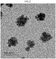
- FIG. 2 is a transmission type electron microscope (TEM) photograph in Example 1.
- dispersion was prepared with the obtained ITO particles. Specifically, 40 mL of pure water (a surfactant was not added) was mixed with 1 g of the ITO particles. Further, the particles and the pure water were mixed in an ultrasonic bus, and thus dispersion was obtained.
- the obtained dispersion was caused to stand still at 20°C for 100 days. As a result, generation of precipitate was not confirmed by eyes. From those points, it was at least confirmed that the dispersion in Example 1 had high stability and excellent dispersibility.
- a zeta potential of the ITO particles in Example 1 was measured.
- the zeta potential was measured through use of a zeta potential measurement device ("ELSZ-2" available from Otsuka Electronics Co., Ltd.) with 1 ⁇ 10 -2 M NaOH and 1 ⁇ 10 -2 M HClO 4 water solution under a condition of ionic strength being 1 ⁇ 10 -2 .
- FIG. 3 is a graph showing measurement results of zeta potentials in Example 1 and Reference Example 1.
- the zeta potential of the ITO particles in Example 1 was substantially equal to the zeta potential of the ITO particles in Reference Example 1. From this point, it can be understood that there was not a large difference between the chemical states of the particles in Example 1 and Reference Example 1. Therefore, it can be understood that the ITO particles in Example 1 had excellent dispersibility even though the chemical state of the particle surfaces was not largely different from that of the ITO particles in Reference Example 1.
- the ITO particles in Example 1 had a specific shape, a contact surface between the particles in the solution was reduced, and aggregation was suppressed. Thus, it can be understood that excellent dispersibility was exerted as a result.
- Example 1 Based on Example 1, the prepared concentrations of In and Sn were changed, and a test was conducted. ITO particles and dispersion thereof were produced similarly to Example 1 except that the ITO particles were produced under the conditions shown in Table 1 and Table 2, and a physical properties thereof were evaluated.
- Example 11 Example 12
- Example 13 Example 14
- Example 16 Reaction time (day(s)) 12h 18h 1day 2days 3days 5days Sn/In of ITO particles (molar ratio) 3.98 4.65 6.52 5.60 5.56 7.40 Crystal orientation ⁇ ⁇ ⁇ ⁇ ⁇ ⁇ Three-dimensional shape of ITO particles Non-rectangular parallelepiped shape Non-rectangular parallelepiped shape Non-rectangular parallelepiped shape Non-rectangular parallelepiped shape
- Non-rectangular parallelepiped shape Non-rectangular parallelepiped shape
- Number of protrusions of ITO particles 9 or more 9 or more 9 or more 9 or more 9 or more 9 or more 9 or more 9 or more Dispersibility of dispersion ⁇ ⁇ ⁇ ⁇ ⁇ ⁇ ⁇
- Example 17 Examp e 1 Reaction temperature (°C) 200°C 190°C Sn/In of ITO particles (molar ratio) 13.6 12. 3 Crystal orientation ⁇ ⁇ Three-dimensional shape of ITO particles Non-rectangular parallelepiped shape Non-rectangular parallelepiped shape Number of protrusions of ITO particles 9 or more 9 or more Dispersibility of dispersion ⁇ ⁇
- Example 1 Reaction temperature 190°C 200°C 190°C 200°C 190°C Prepared In (M) 0.36 0.36 0.54 0.54 0.36 Prepared Sn (M) 0.08 0.08 0.12 0.12 0.04 In/Sn in reaction solution (M ratio) 4.5 4.5 4.5 4.5 9 Sn/In of ITO particles (molar ratio) 12.0 23.2 13.6 20.8 12.
- Example 2 Example 23
- Example 24 Example 25
- Example 26 Example 27
- Non-rectangular parallelepiped shape Non-rectangular parallelepiped shape
- Non-rectangular parallelepiped shape Non-rectangular parallelepiped shape
- ITO particles and dispersion thereof were produced similarly to Example 1 except that the ITO particles were produced under the conditions shown in Table 7 based on Example 1.
- TMAH tetramethylammonium hydroxide
Landscapes
- Chemical & Material Sciences (AREA)
- Organic Chemistry (AREA)
- Inorganic Chemistry (AREA)
- Engineering & Computer Science (AREA)
- Life Sciences & Earth Sciences (AREA)
- Spectroscopy & Molecular Physics (AREA)
- Dispersion Chemistry (AREA)
- Physics & Mathematics (AREA)
- Materials Engineering (AREA)
- Wood Science & Technology (AREA)
- Manufacturing & Machinery (AREA)
- Manufacturing Of Electric Cables (AREA)
- Non-Insulated Conductors (AREA)
- Physical Or Chemical Processes And Apparatus (AREA)
- Photovoltaic Devices (AREA)
Abstract
Description
- The present invention relates to ITO particles, dispersion in which the ITO particles are dispersed, a production method of ITO particles, a production method of dispersion, and a production method of an ITO film. The present invention claims priority to Japanese Patent Application No.
2018-004224 filed on January 15, 2018 2018-119414 filed on June 25, 2018 - With regard to indium tin oxide (ITO) particles,
Patent Literature 1 discloses ITO particles obtained in the following manner. That is, an indium source and a tin source are added to a solution obtained by dissolving a hydroxide of a quaternary ammonium ion in a reducible organic solvent, and a reaction is performed. Subsequently, heating is performed in an autoclave, and aging is performed under self-generative pressure. - PTL 1: Japanese Patent No.
5706797B - A first aspect of the present invention relates to ITO particles having a non-rectangular parallelepiped shape and an aligned crystal orientation inside particles.
- A second aspect of the present invention relates to dispersion including the ITO particles described above, dispersed in a solvent.
- A third aspect of the present invention relates to a production method of ITO particles, including obtaining ITO particles by causing a reaction at a temperature from 190°C to 200°C for 12 hours to 120 hours in a solution containing In salt from 0.09 M to 0.9 M, Sn salt from 0.01 M to 0.2 M, a basic compound, and a solvent, and washing the ITO particles.
- A fourth aspect of the present invention relates to a production method of dispersion, including obtaining ITO particles by causing a reaction at a temperature from 190°C to 200°C for 12 hours to 120 hours in a solution containing In salt from 0.09 M to 0.9 M, Sn salt from 0.01 M to 0.2 M, a basic compound, and a first solvent, washing the ITO particles, and dispersing the washed ITO particles, in a second solvent.
- A fifth aspect of the present invention relates to a production method of an ITO film, including forming the above-mentioned dispersion into mist, bringing the misted dispersion, into contact with a base plate, and drying the dispersion on the base plate after the contact.
- A sixth aspect of the present invention relates to a production method of ITO particles, including obtaining ITO particles by causing a reaction at a temperature from 180°C to 260°C for 12 hours to 120 hours in a solution containing In salt from 0.09 M to 0.9 M, Sn salt from 0.01 M to 0.2 M, a basic compound, and a solvent, and washing the ITO particles.
- A seventh aspect of the present invention relates to a production method of dispersion, including obtaining ITO particles by causing a reaction at a temperature from 180°C to 260°C for 12 hours to 120 hours in a solution containing In salt from 0.09 M to 0.9 M, Sn salt from 0.01 M to 0.2 M, a basic compound, and a first solvent, washing the ITO particles, and dispersing the washed ITO particles, in a second solvent.
-
-
FIG. 1 is a schematic diagram illustrating one example of a film formation device using a mist method in the present embodiment. -
FIG. 2 is a transmission type electron microscope (TEM) photograph in Example 1. -
FIG. 3 is a graph obtained by plotting measurement results of zeta potentials in Example 1 and Reference Example 1. - Hereinafter, description is made on an embodiment for carrying out the present invention (hereinafter, simply referred to as a "present embodiment"). The present embodiment described below is an example for describing the present invention, and is not intended to limit the present invention to the contents described below. Note that, in the drawings, a positional relationship in a vertical direction, a horizontal direction, or the like is based on a positional relationship illustrated in the drawings, unless otherwise specified. Further, a dimensional ratio in the drawings is not limited to the illustrated ratio.
- ITO particles according to the present embodiment have a non-rectangular parallelepiped shape and an aligned crystal orientation inside particles. The ITO particles according to the present embodiment can be evenly atomized and highly dispersed, and may meet demands such as low resistance, high transmittance, and low turbidity (haze), as a material for various transparent electrodes and the like.
- The related-art ITO particles are synthesized by the gel-sol method or the like, and the particle shape is substantially rectangular parallelepiped. With the gel-sol method, a nucleation/nuclear growth reaction takes place in a gel network, and hence the ITO particles produced by the gel-sol method have a rectangular parallelepiped shape in which the crystal phase is reflected, and have high crystallinity.
- In a case where an ITO film is produced by using the related-art ITO particles having a substantially rectangular parallelepiped shape, when the ITO particles are arranged to have surfaces brought into contact with each other, a filling ratio of the film is theoretically 100%. Thus, it has been considered that the ITO particles are preferably formed close to a single crystal structure having a rectangular parallelepiped shape. However, as a result of the inventors' intensive research, it has been revealed that the ITO particles are not actually brought into contact in such a manner and that the particles fill randomly to establish a state in which the particles are brought into point contact or line contact. When the particles with this arrangement are used as a transparent conductive film, the number of conductive paths is reduced, and a resistance value is disadvantageously increased. Further, when dispersibility is low, a filling ratio is reduced, or smoothness of the film is lost due to aggregated particles. The inventors of the present invention consider that there is room for improvement regarding the related-art ITO particles in view of this point.
- The inventors further proceed the examination, and focus on a comprehensive state in a case of the above-mentioned ITO particles having a rectangular parallelepiped shape. Further, the inventors drastically shift the viewpoint, and arrive at the idea that, when a non-rectangular parallelepiped shape with a surface having a number of protrusions thereon can be adopted in place of a substantially rectangular parallelepiped shape, a maximum contact area is reduced while maintaining high crystallinity, and that, as a result, when dispersion is adopted, satisfactory dispersibility may be obtained in the dispersion. Based on this idea, the ITO particles according to the present embodiment have been developed (note that actions and effects according to the present embodiment are not limited thereto).
- In the present embodiment, the "non-rectangular parallelepiped shape" indicates that the number of surfaces forming a particle is seven or more. For example, a substantially rectangular parallelepiped shape and a substantially cubical shape having six surfaces, a three-dimensional shape having five or less surfaces, a spherical shape, and the like are not included as the "non-rectangular parallelepiped shape" described herein. Specifically, the non-rectangular parallelepiped shape of the ITO particles is not considered as a rectangular parallelepiped shape (a shape having eight protrusions). The specific shape of the ITO particles according to the present embodiment preferably has nine or more protrusions.
- The "aligned crystal orientation" in the present embodiment indicates that a spot pattern is confirmed in an electron beam diffraction image of one particle as a whole.
- The average particle diameter of the ITO particles is not particularly limited, and preferably falls within a range from 3 nm to 50 nm, more preferably, from 5 nm to 40 nm. The average particle diameter falls within such range, and thus dispersibility of the ITO particles can further be improved. The average particle diameter can be controlled by adjusting a type and a reaction temperature of a solvent described later.
- A BET specific surface area of the ITO particles is not particularly limited, and preferably falls within a range from 25 cm2/g to 49 cm2/g. Note that the "BET specific surface area" described herein is measured by BET gas adsorption measurement. Note that, in view of dispersibility when dispersion is adopted, the ITO particles preferably satisfy the above-mentioned range of the average particle diameter, and also preferably satisfy the range of the BET specific surface area. The particles satisfying those ranges have such surface area as to exert higher dispersibility.
- With regard to a composition of the ITO particles, a molar ratio of a content amount of Sn to a content amount of In (Sn/In) preferably falls within a range from 3.5 to 24, in view of crystal formation and conductivity.
- The ITO particles according to the present embodiment are preferably produced by the following method instead of the gel-sol method. Specifically, the production method preferably includes: (1) a reaction process of obtaining ITO particles by causing a reaction at a temperature from 180°C to 260°C for 12 hours to 120 hours in a solution containing In salt from 0.09 M to 0.9 M (M = mol/L), Sn salt from 0.01 M to 0.2 M (M = mol/L), a basic compound, and a first solvent; and (2) a process of washing the ITO particles.
- The concentration of the In salt in the reaction solution preferably falls within a range from 0.09 M to 0.9 M, more preferably, 0.09 M to 0.45 M. Further, the concentration of the Sn salt in the reaction solution preferably falls within a range from 0.01 M to 0.2 M, more preferably, from 0.01 M to 0.05 M.
- The concentration of the In salt is preferably from 4.5 times to 9 times, more preferably, from 5 times to 9 times of the concentration of the Sn salt in terms of mole. A particle synthesis reaction is performed with those metal source concentrations, and thus the ITO particles according to the present embodiment can be synthesized easily in one pot.
- The In salt is not particularly limited, and publicly-known one may be used as a raw material for ITO. For example, at least one selected from a group including: metal salt such as InCl3; In2(C2O4)3, In(NO3)3, and In2(SO4)3; and hydrates thereof is exemplified. Among those, anhydrous salt and metal salt are preferred, metal salt is more preferred, and InCl3 is further preferred.
- The Sn salt is not particularly limited, and publicly-known one may be used as a raw material for ITO. For example, at least one selected from a group including: metal salt such as SnCl2, SnCl4, Sn2(C2O4)3, Sn(NO3)2, SnSO4, and InCl3; In2(C2O4)3, In(NO3)3, and In2(SO4)3; and hydrates thereof is exemplified. Among those, anhydrous salt and metal salt are preferred, metal salt is more preferred, and SnCl2 and SnCl4 are further preferred.
- The basic compound is not particularly limited, and is only required to be capable of neutralizing the reaction solution and extracting precipitated In-Sn hydroxides (neutralization and coprecipitation). A publicly-known basic compound may be used, and tetramethylammonium hydroxide (TMAH), sodium hydroxide, and the like are exemplified.
- The concentration of the basic compound in the reaction solution is not particularly limited, and preferably falls within a range from 1 M to 2 M, more preferably, from 1.5 M to 1.7 M, in view of the particle synthesis.
- The first solvent is only required to be capable of dissolving In salt, Sn salt, the basic compound, and other additives used as needed. As the first solvent, publicly-known one can be used, and specific examples preferably include water and alcohols such as methanol, ethanol, isopropanol, ethylene glycol, propylene glycol, polyethylene glycol, and polypropylene glycol, for example.
- In the reaction process (1), other additives may be added as needed without inhibiting the effects of the present embodiment.
- The reaction time in the reaction process (1) preferably falls within a range from 12 hours to 120 hours, more preferably, from 24 hours to 72 hours.
- The reaction temperature in the reaction process (1) preferably falls within a range from 180°C to 260°C, more preferably, from 190°C to 200°C.
- The reaction process (1) may be performed in an open system, but an autoclave is preferably used. With this, generation of coprecipitate of an indium hydroxide and a tin hydroxide that are generated in the reaction system can be promoted.
- A mechanism of obtaining the ITO particles according to the present embodiment by the above-mentioned production method is not known exactly. However, control for the concentrations of the metal salt in the reaction system (M = mol/L), the reaction temperature, the reaction time, and the like are considered to have influence thereon. Control for a shape of monodisperse particles may be performed by the number of nuclei generated in the system and the mass present therein. However, it is considered that, in order to form the protrusions, uneven nucleation is further required on the nuclei while maintaining the nuclei in the gel network, instead of growing the generated nuclei. Thus, it is considered that the metal source concentrations are preferably increased and that the amount of the base with respect to the metal sources are preferably small. With this, concentration of a metal oxide precursor for generating the nuclei may be maintained for a long time period. It is considered that the ITO particles according to the present embodiment can be synthesized by combining the above-mentioned conditions (note that actions and effects according to the present embodiment are not limited thereto).
- In the production method according to the present embodiment, the metal source concentrations are preferably increased, and the base concentration is preferably relatively low with respect to the metal sources. With this, instead of growing the particles after the initial nucleation reaction, uneven nucleation can further be promoted on the generated nuclei. As a result, the ITO particles according to the present embodiment can be synthesized.
- In the present embodiment, a centrifugal separation process is preferably performed between the reaction process (1) and the washing process (2). The centrifugal separation process is preferably performed for ten minutes at 14,000 rpm.
- In the process (2) of washing the ITO particles, washing is preferably performed through use of water, alcohols such as ethanol, or the like. When washing is performed with water, pure water such as distilled water and ion exchanged water (IEW) is preferably used. Further, washing is preferably performed by processing the dispersion with an ultrasonic washing machine.
- Note that, in the related art, a freeze-drying process and a reduction firing process are performed after the reaction process. However, in the production method according to the present embodiment, these processes are not required to be performed. Particularly, a firing process is preferably prevented from being performed after the process (2). With this, aggregation of the ITO particles can be prevented, and a monodisperse state in a dispersion medium can be maintained.
- Dispersion can be obtained by dispersing the ITO particles according to the present embodiment in a second solvent.
- The second solvent is not particularly limited, and water, alcohols such as methanol, ethanol, isopropyl alcohol, ethylene glycol, propylene glycol, polyethylene glycol, and polypropylene glycol, a mixed solvent thereof, and the like are exemplified. Among those, water and alcohols are preferred, and water is more preferred. Specifically, the dispersion according to the present embodiment may be suitably used as aqueous dispersion.
- Other additives and the like may be blended to the dispersion as needed.
- In a case where general ITO particles are dispersed in a solvent for a long time period, a surfactant is required for preventing aggregation of the ITO particles. However, in the dispersion according to the present embodiment, the dispersion in which the ITO particles can be dispersed for a long time period can be obtained without adding a surfactant. Thus, the dispersion according to the present embodiment can be dispersion that does not contain a surfactant substantially, that is, surfactant-free dispersion.
- The surfactant described herein indicates one having a function of adsorbing particle surfaces and causing the particles to be dispersed in a dispersion medium. Specific examples include an anionic surfactant, a cationic surfactant, and a nonionic surfactant.
- In the dispersion according to the present embodiment, a ratio (volume ratio) of the ITO particles with respect to the solvent is not particularly limited, but is preferably 40% or less. With this range, monodispersion can be performed stably for a long period.
- As a production method of dispersion, a method of dispersing the ITO particles according to the present embodiment in a second solvent is exemplified.
- The production method of dispersion is preferably a method including (1) a reaction process of obtaining ITO particles by causing a reaction at a temperature from 180°C to 260°C for 12 hours to 120 hours in a solution containing In salt of 0.09 M to 0.9 M, Sn salt of 0.01 M to 0.2 M, a basic compound, and a first solvent; (2) a process of washing the ITO particles; and (3) a process of dispersing the washed ITO particles in a second solvent.
- Further, the method preferably includes: (1) a reaction process of obtaining ITO particles by causing a reaction at a temperature from 190°C to 200°C for 12 hours to 120 hours in a solution containing In salt from 0.09 M to 0.9 M, Sn salt from 0.01 M to 0.2 M, a basic compound, and a first solvent; (2) a process of washing the ITO particles; and (3) a process of dispersing the washed ITO particles in a second solvent.
- The process (1) and the process (2) may be performed similarly to the process (1) and the process (2) that are already described as the production method of the ITO particles. For example, similarly to the production method of ITO particles described above, the reaction temperature in the process (1) preferably falls within a range from 180°C to 260°C, more preferably, from 190°C to 200°C. Further, as the first solvent, publicly-known one can be used, and water and alcohols such as methanol, ethanol, isopropanol, ethylene glycol, propylene glycol, polyethylene glycol, and polypropylene glycol, are preferably included, for example. Further, the concentration of the In salt in the solution is preferably from 4.5 times to 9 times of the concentration of the Sn salt.
- The dispersion process (3) is performed by adding water to the ITO particles immediately after the washing and mixing the particles and a dispersion medium evenly. The dispersion method is not particularly limited. A stirring method by a stirrer or the like and an ultrasonic dispersion method by an ultrasonic bus or the like may be used, and those methods may be used in combination. Among those, an ultrasonic bus is preferably used.
- An ITO film can be produced through use of the dispersion according to the present embodiment. Specifically, the production method preferably includes: (i) a mist formation process of forming the dispersion according to the present embodiment into mist; (ii) a contact process of bringing the mist dispersion into contact with a base plate; and (iii) a drying process of drying the dispersion present on the base plate after the contact process.
- The ITO film is a material having high conductivity and transparency, and is commonly used as a transparent conductive material. Examples of the production method of ITO film include methods such as spattering and laser deposition. However, with such technique, it is difficult to form an even thin film on a flexible base plate, and characteristics of the ITO having an excellent surface property cannot be fully utilized. Further, a large-scale facility configuration is required in a deposition process or the like. Regarding this point, there is also room for improvement.
- In view of this, the dispersion according to the present embodiment has high dispersibility without sedimentation of components. Thus, a simple mist technique can be used at the time of forming an ITO thin film on a base plate. Further, limitations of a material of the base plate can be relaxed, and thus a film can be formed on the flexible base plate described above. Further, even when the ITO particles according to the present embodiment are at a nano-level (ITO nano particles), high crystallinity and monodispersibility can be maintained stably. Thus, a surface property of a thin film such as conductivity and transparency can also be controlled at a high level.
- The mist formation process (i) is only required to be a method of forming the dispersion into mist. As a method of generating mist, a publicly-known method can be adopted. For example, a pressurization type, a rotary disk type, an ultrasonic type, an electrostatic type, an orifice oscillation type, a steam type, and the like can be adopted. In the present embodiment, for the dispersion of the ITO particles, a physical method of forming mist is preferable. With this, temperature control for liquid and size control for a liquid droplet are facilitated. Further, the dispersion is dealt with as mist. Thus, high controllability is obtained, and a defect such as distortion at the time of forming a thin film, which is caused by the sol-gel method of supplying liquid or the like, is not caused.
- In the mist formation process, carrier gas is used, and thus the mist dispersion can be carried until the subsequent contact process. As the carrier gas, inert gas such as argon, helium, and nitrogen and the like can be used, for example.
- Further, between the process (i) and the process (ii), a process of uniforming the mist with a mist trap and a stagnation process of providing a stagnation period (stagnation portion) for the mist may be performed.
- The contact process (ii) is not particularly limited as long as the method enables the mist to be brought into contact with the base plate, and a publicly-known technique can be adopted. For example, there is exemplified a method of spraying, onto the base plate, fine liquid droplets obtained by a mist method in the mist formation process. Examples of the mist method include ultrasonic spray, a mist CVD method, a linear source type, and a hot wall type. Selection may be made among those methods in consideration of a film thickness of the ITO film formed on the base plate, a size of liquid droplets to be sprayed, and the like.
- The contact process may be performed under any one of atmospheric pressure, reduced pressure, and vacuum. In view of convenience, atmospheric pressure is preferable.
- Further, the mist dispersion is applied on the base plate subjected to masking, and thus a fine and minute pattern can be formed, which is suitable when ITO nano particles are formed into a thin film on a base plate and so on. With this, dimension control can be performed at high accuracy.
- When water is used as the solvent of the dispersion, a water-repellent masking material (water-repellent film) is preferably used as a masking material. With this, the pattern can be formed at higher accuracy.
- Further, limitations of a material of a base material can be relaxed, and thus a film base material that is thin and has high flexibility (also referred to as a sheet base material) can also be used as the base material. Moreover, continuous production in, for example, a roll-to-roll manner is also enabled.
- For example, publicly-known materials can be used as the base material. Glass, polyethylene terephthalate (PET), polyethylene naphthalate (PEN), polyethersulfone (PES), polyether imide, polyetheretherketone, polyphenylene sulfide, polyarylate, polyimide, polycarbonate (PC), cellulose triacetate (TAC), cellulose acetate propionate (CAP), and the like are exemplified.
- In the drying process (iii), the solvent in the dispersion sprayed on the base plate is removed. For example, the solvent is vaporized by photoirradiation with infrared light or the like, or heating, and thus an ITO film is formed on the surface of the base plate. Heating temperature can be set in consideration of a boiling point of the solvent, a softening point of the base plate, and other factors that may influence a physical property of the ITO film. The softening point of the base plate described herein indicates temperature at which softening and deformation of the base plate start when the base plate is heated, and can be obtained by a test method according to JIS K7191-1, for example.
- After the process (iii), a process of annealing the base plate having the ITO film formed thereon (annealing process), a UV irradiation process, or the like for the purpose of modifying the base material, for example, imparting hydrophilicity, and the like may be performed as needed.
- Here, regarding a film formation device,
FIG. 1 is a schematic diagram illustrating one example of a film formation device using the mist method in the present embodiment. Afilm formation device 1 includes a first tank in which mist containing fine particles is generated, a second tank being a mist trap for uniforming the mist, and a third tank in which the mist is sprayed onto abase plate 10. - The above-mentioned dispersion is stored as a raw material solution S in the first tank. The above-mentioned particles may be used for particles in the dispersion, and nano fine particles are preferable. Here, description is made on a case where ITO fine particles are used as the particles.
- In the first tank,
air 20 is caused to flow for the purpose of forming a flow path of the mist. - An
ultrasonic oscillator 30 is stored in the first tank. Theultrasonic oscillator 30 forms the dispersion containing the ITO fine particles into mist. A particle diameter of the mist is not particularly limited, and is preferably 10 µm or less (a range of, for example, from 1 µm to 10 µm). The mist generated in the first tank is conveyed to the second tank through a pipe provided to the first layer. In the second tank, excessive mist stagnates in the lower part of the tank, and the mist having a further uniformed particle diameter is conveyed to the third layer through a pipe provided to the second tank. Such configuration that the mist having a particle diameter of 5 µm or less (a range of, for example, from 1 µm to 5 µm) is conveyed from the second tank to the third tank is preferable. - The
base plate 10 is arranged in the third tank, the mist conveyed from the second tank is sprayed onto the base plate. In the third tank, the mist is sprayed onto thebase plate 10 for a predetermined time period. Further, a dispersion medium in the mist adhering to thebase plate 10 is vaporized, and thus an ITO film is formed on the surface of thebase plate 10. Note that, when a certain time period elapses from the spraying, the mist newly adheres onto thebase plate 10 before the mist is vaporized. Thus, the dispersion formed into the liquid droplets flows down, and a uniform ITO film is not formed on thebase plate 10. A timing at which spraying of the mist onto thebase plate 10 is stopped may be a timing at which the mist containing the ITO fine particles is liquefied and flows down from thebase plate 10 or a timing at which the ITO film having a desired film thickness is formed on thebase plate 10. - In the third tank, when the
base plate 10 is heated excessively, deformation may be caused due to softening. Thus, in the third tank, the mist is preferably sprayed at temperature lower than the softening point of the base plate, to form the ITO film. Further, when thebase plate 10 is heated at predetermined temperature or higher at the time of spraying the mist, the ITO fine particles adhering to thebase plate 10 are aggregated. As a result, evenness of the film is degraded, and a conductive network among the particles is inhibited. Thus, an ITO film having a high resistance value is formed. Therefore, more preferably, it is configured that the mist is sprayed at temperature of 40°C or less (a range of, for example, from 10°C to 40°C), to form the ITO film. - In a case where a metal oxide film is selectively formed on the
base plate 10, a water-repellent film is selectively formed on thebase plate 10 in advance, so that the mist is caused to adhere to a hydrophilic part. In this case, when thebase plate 10 is arranged horizontally, the dispersion adhering to a water-repellent part is not repelled, and a metal oxide film cannot be formed selectively. Thus, in the third tank, the mist is preferably sprayed onto thebase plate 10 inclined with respect to the horizontal plane. - Similarly, in the third tank, the mist is preferably sprayed onto the
base plate 10 inclined with respect to a plane perpendicular to a spray direction of the mist. This is for the purpose of removing excessing ITO fine particles adhering to the water-repellent part, with a blowing force of the sprayed mist. - Note that the mist trap in the second tank may be omitted in the film formation device. In this case, relatively large liquid droplets can be subjected to filtering, and the ITO film can be formed accurately even when a hydrophilic/water-repellent pattern on the base plate is fine and minute.
- Further, regarding the method of generating mist, in addition to the above-mentioned method using the
ultrasonic oscillator 30, an electrostatic type in which mist is generated by applying a voltage directly to a tube for spraying liquid droplets, a pressurization type in which generated mist scatters by causing gas at a flow rate increased due to pressurization to collide against liquid, a rotary disk type in which liquid droplets drip onto a disk rotating at a high speed to cause generated mist to scatter with a centrifugal force, an orifice oscillation type in which, when liquid droplets are caused to pass through an orifice plate having micro sized pores, the liquid droplets are cut by applying oscillation by a piezoelectric element or the like to generate micro sized liquid droplets, and the like can be adopted. Selection is made as appropriate from those methods of generating mist in accordance with cost, performance, and the like. As a matter of course, a plurality of methods may be combined to generate mist. - The present invention is described more in detail with reference to Examples and Comparative Examples given below. However, the present invention is not limited at all by the examples given below.
- A multipurpose X-ray diffractometer ("Ultima-IV" available from Rigaku Corporation) was used as a measurement device. Measurement was performed under the following conditions: a radiation source of CuKα; an output of 40 kV and 40 mA; and a detector being "D/teX Ultra".
- An ICP emission spectrum analyzer ("Optima 3300" available from PerkinElmer, Inc.,) was used as a measurement device.
- A transmission type electron microscope (TEM, "JEM-2100" available from Hitachi, Ltd.) was used as a measurement device, and measurement was performed under a condition, that is, power of 120k.
- A TEM photographed image of ITO particles was subjected to image processing through use of image processing software "imageJ 1.51j8". Specifically, a scale of one pixel was subjected to processing so as to correspond to an actual image, and the image was binarized.
- As an average particle diameter of the ITO particles, a size of crystallite, which was calculated from the Scherrer equation through use of a peak of 400 surfaces of an XRD pattern measured by the above-mentioned X-ray diffractometer, was adopted.
- In a reactor vessel, 7.5 mL of methanol as a solvent and 1.6 M of tetramethylammonium hydroxide (TMAH) as a basic catalyst were prepared. Further, a methanol solution was produced so that the In concentration was 0.36 M and the Sn concentration was 0.04 M in the reaction solution (In/Sn = 9 in the reaction solution). This was added in the above-mentioned TMAH methanol solution, was stirred for 10 minutes, and then was heated at 190°C for a day to progress a reaction. After that, centrifugal separation was performed at 14,000 rpm for 10 minutes. Subsequently, washing was performed twice with ethanol and twice with ion exchanged water, and ITO particles were obtained.
The obtained ITO particles were blue on the surfaces. - According to the XRD, a diffraction pattern attributable to indium oxide (In2O3) having the same crystal structure as that of ITO was successfully obtained. With this, it was confirmed that ITO was synthesized. With the ICP, it was confirmed that Sn/In (molar ratio) of the ITO particles was equal to 12.3.
FIG. 2 is a transmission type electron microscope (TEM) photograph in Example 1. - Subsequently, dispersion was prepared with the obtained ITO particles. Specifically, 40 mL of pure water (a surfactant was not added) was mixed with 1 g of the ITO particles. Further, the particles and the pure water were mixed in an ultrasonic bus, and thus dispersion was obtained.
- The obtained dispersion was caused to stand still at 20°C for 100 days. As a result, generation of precipitate was not confirmed by eyes. From those points, it was at least confirmed that the dispersion in Example 1 had high stability and excellent dispersibility.
- As an index for evaluating dispersibility in viewpoint of a chemical state of the particles, a zeta potential of the ITO particles in Example 1 was measured. The zeta potential was measured through use of a zeta potential measurement device ("ELSZ-2" available from Otsuka Electronics Co., Ltd.) with 1 × 10⁻² M NaOH and 1 × 10⁻² M HClO4 water solution under a condition of ionic strength being 1 × 10⁻².
- Note that, as Reference Example 1, a zeta potential of ITO particles (a particle shape was substantially rectangular parallelepiped and the number of protrusions for each particle was eight), which were produced in accordance with a method described in Chem. Lett., 42, 738 (2013), was measured under the same conditions. As a result, an isoelectric point (pH 0) of the ITO particles in Example 1 was 10.27, and an isoelectric point (pH 0) in Reference Example 1 was 9.73.
FIG. 3 is a graph showing measurement results of zeta potentials in Example 1 and Reference Example 1. - As shown in
FIG. 3 , the zeta potential of the ITO particles in Example 1 was substantially equal to the zeta potential of the ITO particles in Reference Example 1. From this point, it can be understood that there was not a large difference between the chemical states of the particles in Example 1 and Reference Example 1. Therefore, it can be understood that the ITO particles in Example 1 had excellent dispersibility even though the chemical state of the particle surfaces was not largely different from that of the ITO particles in Reference Example 1. The ITO particles in Example 1 had a specific shape, a contact surface between the particles in the solution was reduced, and aggregation was suppressed. Thus, it can be understood that excellent dispersibility was exerted as a result. - Based on Example 1, the prepared concentrations of In and Sn were changed, and a test was conducted. ITO particles and dispersion thereof were produced similarly to Example 1 except that the ITO particles were produced under the conditions shown in Table 1 and Table 2, and a physical properties thereof were evaluated.
- Production conditions and evaluation results of dispersion in Examples 1 to 10 are shown in Table 1 and Table 2. Note that, in the item "crystal orientation", a case where a spot pattern was confirmed by the electron beam diffraction method is marked with a circle "o", and the opposite case is marked with a cross mark "x". The item "number of protrusions of ITO particle" indicates the number of protrusions for each particle, which was counted based on the above-mentioned method, and does not indicate the number of protrusions on one crystal surface. For example, description of "9 or more" as the number of protrusions indicates that nine or more protrusions were present for each ITO particle. In the item "dispersibility of dispersion", for evaluation on dispersibility, a case where generation of precipitate was not confirmed by eyes is marked with a circle "o", and a case where generation of precipitate was confirmed is marked with a cross mark "x".
[Table 1] Example 1 Example 2 Example 3 Example 4 Example 5 Prepared In (M) 0.36 0.225 0.27 0.315 0.45 Prepared Sn (M) 0.04 0.025 0.03 0.035 0.05 In/Sn in reaction solution (M ratio) 9 9 9 9 9 Sn/In of ITO particles (molar ratio) 12.3 12.7 12.7 13.2 7.66 Crystal orientation ○ ○ ○ ○ ○ Three-dimensional shape of ITO particles Non-rectangular parallelepiped shape Non-rectangular parallelepiped shape Non-rectangular parallelepiped shape Non-rectangular parallelepiped shape Non-rectangular parallelepiped shape Number of protrusions of ITO particles 9 or more 9 or more 9 or more 9 or more 9 or more Dispersibilit) of dispersion ○ ○ ○ ○ ○ [Table 2] Example 6 Example 7 Example 8 Example 9 Example 10 Prepared In (M) 0.54 0.63 0.72 0.81 0. 9 Prepared Sn (M) 0.06 0.07 0.08 0.09 0.1 In/Sn in reaction solution (M ratio) 9 9 9 9 9 Sn/In of ITO particles (molar ratio) 8. 85 5.70 6.71 8.43 5.25 Crystal orientation ○ ○ ○ ○ ○ Three-dimensional shape of ITO particle Non-rectangular parallelepiped shape Non-rectangular parallelepiped shape Non-rectangular parallelepiped shape Non-rectangular parallelepiped shape Non-rectangular parallelepiped shape Number of protrusions of ITO particles 9 or more 9 or more 9 or more 9 or more 9 or more Dispersibility of dispersion ○ ○ ○ ○ ○ - Based on Example 1, the reaction time in the reaction process was changed, and a test was conducted. ITO particles and dispersion thereof were produced similarly to Example 1 except that the ITO particles were produced under the conditions shown in Table 3.
[Table 3] Example 11 Example 12 Example 13 Example 14 Example 15 Example 16 Reaction time (day(s)) 12h 18h 1day 2days 3days 5days Sn/In of ITO particles (molar ratio) 3.98 4.65 6.52 5.60 5.56 7.40 Crystal orientation ○ ○ ○ ○ ○ ○ Three-dimensional shape of ITO particles Non-rectangular parallelepiped shape Non-rectangular parallelepiped shape Non-rectangular parallelepiped shape Non-rectangular parallelepiped shape Non-rectangular parallelepiped shape Non-rectangular parallelepiped shape Number of protrusions of ITO particles 9 or more 9 or more 9 or more 9 or more 9 or more 9 or more Dispersibility of dispersion ○ ○ ○ ○ ○ ○ - Based on Example 1, the reaction temperature in the reaction process was changed, and a test was conducted. ITO particles and dispersion thereof were produced similarly to Example 1 except that the ITO particles were produced under the conditions shown in Table 4. The average particle diameter of the obtained ITO particles was 33.32 nm.
[Table 4] Example 17 Examp e 1Reaction temperature (°C) 200°C 190°C Sn/In of ITO particles (molar ratio) 13.6 12. 3 Crystal orientation ○ ○ Three-dimensional shape of ITO particles Non-rectangular parallelepiped shape Non-rectangular parallelepiped shape Number of protrusions of ITO particles 9 or more 9 or more Dispersibility of dispersion ○ ○ - Based on Example 1, the Sn doping amount was changed, and a test was conducted. ITO particles and dispersion thereof were produced similarly to Example 1 except that the ITO particles were produced under the conditions shown in Table 5. Note that the average particle diameter of the ITO particles in Example 19 was 30.72 nm.
[Table 5] Example 18 Example 19 Example 20 Example 21 Example 1 Reaction temperature 190°C 200°C 190°C 200°C 190°C Prepared In (M) 0.36 0.36 0.54 0.54 0.36 Prepared Sn (M) 0.08 0.08 0.12 0.12 0.04 In/Sn in reaction solution (M ratio) 4.5 4.5 4.5 4.5 9 Sn/In of ITO particles (molar ratio) 12.0 23.2 13.6 20.8 12. 3 Crystal orientation ○ ○ ○ ○ ○ rhree-dimensional shape of ITO particles Non-rectangular parallelepiped shape Non-rectangular parallelepiped shape Non-rectangular parallelepiped shape Non-rectangular parallelepiped shape Non-rectangular parallelepiped shape Number of protrusions of ITO particles 9 or more 9 or more 9 or more 9 or more 9 or more Dispersibility of dispersion ○ ○ ○ ○ ○ - Based on Example 1, the reaction time in the reaction process was changed, and a test was conducted. ITO particles and dispersion thereof were produced similarly to Example 1 except that the ITO particles were produced under the conditions shown in Table 6.
[Table 6] Example 22 Example 23 Example 24 Example 25 Example 26 Example 27 Example 28 Example 1 Reaction time (day(s)) 12h 18h 1day 2days 3days 5days 7days 1day Prepared In (M) 0.36 0.36 0.36 0.36 0.36 0.36 0.36 0.36 Prepared Sn (M) 0.04 0.04 0.04 0.04 0.04 0.04 0.04 0.04 In/Sn in reaction solution (M ratio) 9 9 9 9 9 9 9 9 Sn/In of ITO particles (molar ratio) 5.26 5.89 8.85 6.68 5.45 6.31 4.89 12.3 Crystal orientation ○ ○ ○ ○ ○ ○ ○ ○ Three-dimensional shape of ITO particles Non-rectangular parallelepiped shape Non-rectangular parallelepiped shape Non-rectangular parallelepiped shape Non-rectangular parallelepiped shape Non-rectangular parallelepiped shape Non-rectangular parallelepiped shape Non-rectangular parallelepiped shape Non-rectangular parallelepiped shape Number of protrusions of ITO particles 9 or more 9 or more 9 or more 9 or more 9 or more 9 or more 9 or more 9 or more Dispersibility of dispersion ○ ○ ○ ○ ○ ○ ○ ○ - ITO particles and dispersion thereof were produced similarly to Example 1 except that the ITO particles were produced under the conditions shown in Table 7 based on Example 1.
- For example, in Example 29, in a reactor vessel, 7.5 mL of ethylene glycol as a solvent and 1.6 M of tetramethylammonium hydroxide (TMAH) as a basic catalyst were prepared. Further, ethylene glycol solution was produced so that the In concentration was 0.36 M and the Sn concentration was 0.04 M in the reaction solution (In/Sn = 9 in the reaction solution). This was added in the above-mentioned TMAH ethylene glycol solution, was stirred for 10 minutes, and then was heated at 230°C for a day to progress a reaction. After that, centrifugal separation was performed at 14,000 rpm for 10 minutes. Subsequently, washing was performed twice with ethanol and twice with ion exchanged water, and ITO particles were obtained. The obtained ITO particles were blue on the surfaces.
-
Table 7 Example 29 Example 30 Example 31 Example 32 Example 33 Example 34 Example 35 Example 36 Example 37 Reaction temperature (°C) 230 230 230 240 240 240 250 250 250 Prepared In (M) 0.36 0.36 0.36 0.36 0.36 0.36 0.36 0.36 0.36 Prepared Sn (M) 0.04 0.06 0.08 0.04 0.06 0.08 0.04 0.06 0.08 In/Sn in reaction solution (M ratio) 9 6 4.5 9 6 4.5 9 6 4.5 Sn/In of ITO particles (molar ratio) 12.6 17.3 27.1 11.9 17.8 26.7 12.6 18.9 28.4 Crystal orientation ○ ○ ○ ○ ○ ○ ○ ○ ○ Three-dimensional shape of ITO particles Non-rectangular parallelepiped shape Non-rectangular parallelepiped shape Non-rectangular parallelepiped shape Non-rectangular parallelepiped shape Non-rectangular parallelepiped shape Non-rectangular parallelepiped shape Non-rectangular parallelepiped shape Non-rectangular parallelepiped shape Non-rectangular parallelepiped shape Number of protrusions of ITO particles 9 or more 9 or more 9 or more 9 or more 9 or more 9 or more 9 or more 9 or more 9 or more Dispersibility of dispersion ○ ○ ○ ○ ○ ○ ○ ○ ○ Average particle diameter (nm) 9.25 9.31 9.58 9.68 10.91 9.82 13.99 11.72 10.72 - Synthesis of ITO particles was attempted under conditions similar to those in Example 1, except that a condition was changed so that the In concentration was 1.8 M and the Sn concentration was 0.2 M in the reaction solution. As a result, in an XRD spectrum, a diffraction pattern of indium oxide having the same crystal structure as that of ITO was not confirmed, but a diffraction pattern attributed to indium oxyhydroxide was confirmed. Specifically, indium oxyhydroxide was generated, and ITO particles were not synthesized successfully.
- Synthesis of ITO particles was attempted under conditions similar to those in Example 1, except that the reaction time was changed to six hours. As a result, according to the TEM, unreacted metal sources were confirmed, and ITO particles were not synthesized successfully.
- Synthesis of ITO particles was attempted under conditions similar to those in Example 1, except that the reaction temperature was changed to 150°C. As a result, in an XRD spectrum, a diffraction pattern of indium oxide having the same crystal structure as that of ITO was not confirmed, but a diffraction pattern attributed to indium oxyhydroxide was confirmed. Specifically, indium oxyhydroxide was generated, and ITO particles were not synthesized successfully.
- Synthesis of ITO particles was attempted under conditions similar to those in Example 1, except that the reaction temperature was changed to 130°C. As a result, in an XRD spectrum, a diffraction pattern of indium oxide having the same crystal structure as that of ITO was not confirmed, but a diffraction pattern attributed to indium oxyhydroxide was confirmed. Specifically, indium oxyhydroxide was generated, and ITO particles were not synthesized successfully.
- Synthesis of ITO particles was attempted under conditions similar to those in Example 1, except that the reaction temperature was changed to 100°C. As a result, in an XRD spectrum, a diffraction pattern of indium oxide having the same crystal structure as that of ITO was not confirmed, but a diffraction pattern attributed to indium oxyhydroxide was confirmed. Specifically, indium oxyhydroxide was generated, and ITO particles were not synthesized successfully.
-
- 1
- Film formation device
- 10
- Plate
- 20
- Air
- 30
- Ultrasonic oscillator
- S
- Raw material solution
Claims (18)
- ITO particles, having a non-rectangular parallelepiped shape and an aligned crystal orientation inside particles.
- The ITO particles according to claim 1, wherein nine or more protrusions are provided.
- The ITO particles according to claim 1 or 2, wherein a molar ratio of a content amount of Sn to a content amount of In (Sn/In) falls within a range from 3.5 to 24.
- Dispersion comprising the ITO particles according to any one of claims 1 to 3, dispersed in a solvent.
- The dispersion according to claim 4, wherein the solvent comprises water.
- The dispersion according to claim 4 or 5, wherein the dispersion is substantially prevented from comprising a surfactant.
- The dispersion according to any one of claims 4 to 6, wherein a ratio of a volume of the ITO particles to a volume of the solvent is 40% or less.
- A production method of ITO particles, comprising:obtaining ITO particles by causing a reaction at a temperature from 190°C to 200°C for 12 hours to 120 hours in a solution containing In salt from 0.09 M to 0.9 M, Sn salt from 0.01 M to 0.2 M, a basic compound, and a solvent; andwashing the ITO particles.
- The production method of ITO particles according to claim 8, wherein, in the solution, concentration of the In salt is from 4.5 times to 9 times of concentration of the Sn salt in terms of mole.
- A production method of dispersion, comprising:obtaining ITO particles by causing a reaction at a temperature from 190°C to 200°C for 12 hours to 120 hours in a solution containing In salt from 0.09 M to 0.9 M, Sn salt from 0.01 M to 0.2 M, a basic compound, and a first solvent;washing the ITO particles; anddispersing the washed ITO particles, in a second solvent.
- The production method of dispersion according to claim 10, wherein, in the solution, concentration of the In salt is from 4.5 times to 9 times of concentration of the Sn salt.
- A production method of an ITO film, comprising:forming the dispersion according to any one of claims 4 to 7 into mist;bringing the misted dispersion, into contact with a base plate; anddrying the dispersion on the base plate after the contact.
- A production method of ITO particles, comprising:obtaining ITO particles by causing a reaction at a temperature from 180°C to 260°C for 12 hours to 120 hours in a solution containing In salt from 0.09 M to 0.9 M, Sn salt from 0.01 M to 0.2 M, a basic compound, and a solvent; andwashing the ITO particles.
- The production method of ITO particles according to claim 13, wherein the solvent comprises ethylene glycol.
- The production method of ITO particles according to claims 13 or 14, wherein, in the solution, concentration of the In salt is from 4.5 times to 9 times of concentration of the Sn salt.
- A production method of dispersion, comprising:obtaining ITO particles by causing a reaction at a temperature from 180°C to 260°C for 12 hours to 120 hours in a solution containing In salt from 0.09 M to 0.9 M, Sn salt from 0.01 M to 0.2 M, a basic compound, and a first solvent;washing the ITO particles; anddispersing the washed ITO particles, in a second solvent.
- The production method of dispersion according to claim 16, wherein the first solvent comprises ethylene glycol.
- The production method of dispersion according to claim 16 or 17, wherein, in the solution, concentration of the In salt is from 4.5 times to 9 times of concentration of the Sn salt.
Applications Claiming Priority (3)
| Application Number | Priority Date | Filing Date | Title |
|---|---|---|---|
| JP2018004224 | 2018-01-15 | ||
| JP2018119414 | 2018-06-25 | ||
| PCT/JP2018/043511 WO2019138707A1 (en) | 2018-01-15 | 2018-11-27 | Ito particles, dispersion, production method of ito particles, production method of dispersion, and production method of ito film |
Publications (2)
| Publication Number | Publication Date |
|---|---|
| EP3741727A1 true EP3741727A1 (en) | 2020-11-25 |
| EP3741727A4 EP3741727A4 (en) | 2021-10-06 |
Family
ID=67219574
Family Applications (1)
| Application Number | Title | Priority Date | Filing Date |
|---|---|---|---|
| EP18899507.0A Pending EP3741727A4 (en) | 2018-01-15 | 2018-11-27 | ITO PARTICLES AS WELL AS A PROCESS FOR THE MANUFACTURE OF THE SAME, A LIQUID DISPERSION AS WELL AS A PROCESS FOR THE MANUFACTURE OF THE SAME, AND A PROCESS FOR THE MANUFACTURE OF ITO FILM |
Country Status (7)
| Country | Link |
|---|---|
| US (1) | US11952508B2 (en) |
| EP (1) | EP3741727A4 (en) |
| JP (1) | JP7089537B2 (en) |
| KR (1) | KR102461412B1 (en) |
| CN (1) | CN111601773A (en) |
| TW (2) | TWI722350B (en) |
| WO (1) | WO2019138707A1 (en) |
Families Citing this family (3)
| Publication number | Priority date | Publication date | Assignee | Title |
|---|---|---|---|---|
| KR102461412B1 (en) * | 2018-01-15 | 2022-10-31 | 고쿠리츠다이가쿠호진 도호쿠다이가쿠 | ITO particles, dispersions, methods for producing ITO particles, methods for producing dispersions, and methods for producing ITO membranes |
| CN115321585B (en) * | 2022-08-09 | 2023-08-11 | 先导薄膜材料(安徽)有限公司 | Indium hydroxide washing process |
| WO2025186894A1 (en) * | 2024-03-05 | 2025-09-12 | 株式会社ニコン | Ito dispersion, ito film, multilayer object including ito film, and method for producing ito dispersion and ito film |
Family Cites Families (17)
| Publication number | Priority date | Publication date | Assignee | Title |
|---|---|---|---|---|
| JPS5453880A (en) | 1977-10-06 | 1979-04-27 | Hitachi Medical Corp | Overhead traveling xxray tube supporting device |
| JP5589214B2 (en) * | 2007-10-01 | 2014-09-17 | Dowaエレクトロニクス株式会社 | ITO powder and manufacturing method thereof, coating material for transparent conductive material, and transparent conductive film |
| JP5472589B2 (en) * | 2008-07-10 | 2014-04-16 | 国立大学法人東北大学 | Production method of ITO particles |
| JP2010047448A (en) * | 2008-08-22 | 2010-03-04 | Tohoku Univ | Synthesis method of indium tin oxide (ito) nanoparticle and organic modified ito nanoparticle |
| EP2174989A1 (en) * | 2008-10-08 | 2010-04-14 | ChemIP B.V. | Aqueous metaloxide dispersions and coating materials prepared thereof. |
| JP5618229B2 (en) * | 2009-12-18 | 2014-11-05 | 国立大学法人東北大学 | ITO powder, method for producing ITO particles, coating for transparent conductive material and transparent conductive film |
| JP5754580B2 (en) * | 2010-10-26 | 2015-07-29 | 三菱マテリアル電子化成株式会社 | Indium tin oxide powder |
| JP5706797B2 (en) * | 2011-10-20 | 2015-04-22 | 三井金属鉱業株式会社 | Tin-doped indium oxide particles |
| CA2787584A1 (en) * | 2012-08-22 | 2014-02-22 | Hy-Power Nano Inc. | Method for continuous preparation of indium-tin coprecipitates and indium-tin-oxide nanopowders with substantially homogeneous indium/tin composition, controllable shape and particle size |
| CN103508484B (en) * | 2013-09-30 | 2015-03-25 | 西北大学 | A kind of infrared low emissivity nanocrystalline film material SnO2 and preparation method thereof |
| CN110085370B (en) | 2013-10-30 | 2021-12-10 | 株式会社尼康 | Method for producing thin film |
| JP6732201B2 (en) * | 2015-11-11 | 2020-07-29 | 国立大学法人京都工芸繊維大学 | Light emitting element |
| JP6626709B2 (en) | 2015-12-24 | 2019-12-25 | 三菱マテリアル電子化成株式会社 | ITO conductive film and paint for forming the ITO conductive film |
| JP6771325B2 (en) | 2016-07-07 | 2020-10-21 | 大阪瓦斯株式会社 | Combined heat and power system |
| JP6834521B2 (en) | 2017-01-23 | 2021-02-24 | スズキ株式会社 | Exhaust heat recovery device |
| KR102461412B1 (en) * | 2018-01-15 | 2022-10-31 | 고쿠리츠다이가쿠호진 도호쿠다이가쿠 | ITO particles, dispersions, methods for producing ITO particles, methods for producing dispersions, and methods for producing ITO membranes |
| JPWO2019138708A1 (en) * | 2018-01-15 | 2021-01-07 | 国立大学法人東北大学 | Method for Producing ITO Particles, Dispersion Solution and ITO Film |
-
2018
- 2018-11-27 KR KR1020207020498A patent/KR102461412B1/en active Active
- 2018-11-27 CN CN201880086439.7A patent/CN111601773A/en active Pending
- 2018-11-27 EP EP18899507.0A patent/EP3741727A4/en active Pending
- 2018-11-27 WO PCT/JP2018/043511 patent/WO2019138707A1/en not_active Ceased
- 2018-11-27 JP JP2019564327A patent/JP7089537B2/en active Active
- 2018-12-14 TW TW107145209A patent/TWI722350B/en active
- 2018-12-14 TW TW110105775A patent/TWI764573B/en active
-
2020
- 2020-07-14 US US16/928,833 patent/US11952508B2/en active Active
Also Published As
| Publication number | Publication date |
|---|---|
| JP7089537B2 (en) | 2022-06-22 |
| WO2019138707A1 (en) | 2019-07-18 |
| TW202120437A (en) | 2021-06-01 |
| KR102461412B1 (en) | 2022-10-31 |
| TWI722350B (en) | 2021-03-21 |
| KR20200098644A (en) | 2020-08-20 |
| CN111601773A (en) | 2020-08-28 |
| TW201936504A (en) | 2019-09-16 |
| JPWO2019138707A1 (en) | 2021-01-07 |
| US11952508B2 (en) | 2024-04-09 |
| EP3741727A4 (en) | 2021-10-06 |
| US20210002494A1 (en) | 2021-01-07 |
| TWI764573B (en) | 2022-05-11 |
Similar Documents
| Publication | Publication Date | Title |
|---|---|---|
| US11692104B2 (en) | ITO particles, dispersion, and production method of ITO film | |
| JP5589214B2 (en) | ITO powder and manufacturing method thereof, coating material for transparent conductive material, and transparent conductive film | |
| US11952508B2 (en) | ITO particles, dispersion, production method of ITO particles, production method of dispersion, and production method of ITO film | |
| Kumar et al. | Variation in chemical bath pH and the corresponding precursor concentration for optimizing the optical, structural and morphological properties of ZnO thin films | |
| US10759665B2 (en) | Silica particle dispersion and method for producing the same | |
| EP2174993A1 (en) | Conductive ink, conductive coating therefrom and method for producing the same | |
| EP2305608A1 (en) | Process for producing ito particles, ito powder, coating material for transparent electroconductive material, and transparent electroconductive film | |
| CN107107050B (en) | Photocatalyst composite particle and method for producing the same | |
| JP2017075077A (en) | Production method of zinc oxide film | |
| JP2016138296A (en) | Method for producing copper nanoparticles | |
| TW202600467A (en) | ITO dispersion, ITO membrane, laminate with ITO membrane, and manufacturing method of ITO dispersion and ITO membrane. | |
| CN103903674A (en) | ITO powder, coating for ITO conductive film and method for manufacturing transparent conductive film | |
| EP3417019B1 (en) | Ink formulations based on (semi)conducting nanoparticles | |
| HK40001859B (en) | Ink formulations based on (semi)conducting nanoparticles | |
| HK40001859A (en) | Ink formulations based on (semi)conducting nanoparticles |
Legal Events
| Date | Code | Title | Description |
|---|---|---|---|
| STAA | Information on the status of an ep patent application or granted ep patent |
Free format text: STATUS: THE INTERNATIONAL PUBLICATION HAS BEEN MADE |
|
| PUAI | Public reference made under article 153(3) epc to a published international application that has entered the european phase |
Free format text: ORIGINAL CODE: 0009012 |
|
| STAA | Information on the status of an ep patent application or granted ep patent |
Free format text: STATUS: REQUEST FOR EXAMINATION WAS MADE |
|
| 17P | Request for examination filed |
Effective date: 20200715 |
|
| AK | Designated contracting states |
Kind code of ref document: A1 Designated state(s): AL AT BE BG CH CY CZ DE DK EE ES FI FR GB GR HR HU IE IS IT LI LT LU LV MC MK MT NL NO PL PT RO RS SE SI SK SM TR |
|
| AX | Request for extension of the european patent |
Extension state: BA ME |
|
| DAV | Request for validation of the european patent (deleted) | ||
| DAX | Request for extension of the european patent (deleted) | ||
| A4 | Supplementary search report drawn up and despatched |
Effective date: 20210906 |
|
| RIC1 | Information provided on ipc code assigned before grant |
Ipc: C01G 19/02 20060101ALI20210831BHEP Ipc: H01B 13/00 20060101ALI20210831BHEP Ipc: H01B 5/00 20060101ALI20210831BHEP Ipc: H01B 1/22 20060101ALI20210831BHEP Ipc: H01B 1/02 20060101ALI20210831BHEP Ipc: C01G 19/00 20060101AFI20210831BHEP |