EP3741721A1 - Method for cleaning and sterilizing beverage filling device - Google Patents
Method for cleaning and sterilizing beverage filling device Download PDFInfo
- Publication number
- EP3741721A1 EP3741721A1 EP19741154.9A EP19741154A EP3741721A1 EP 3741721 A1 EP3741721 A1 EP 3741721A1 EP 19741154 A EP19741154 A EP 19741154A EP 3741721 A1 EP3741721 A1 EP 3741721A1
- Authority
- EP
- European Patent Office
- Prior art keywords
- drink
- sip
- cip
- supply piping
- cleaner
- Prior art date
- Legal status (The legal status is an assumption and is not a legal conclusion. Google has not performed a legal analysis and makes no representation as to the accuracy of the status listed.)
- Granted
Links
Images




Classifications
-
- B—PERFORMING OPERATIONS; TRANSPORTING
- B67—OPENING, CLOSING OR CLEANING BOTTLES, JARS OR SIMILAR CONTAINERS; LIQUID HANDLING
- B67C—CLEANING, FILLING WITH LIQUIDS OR SEMILIQUIDS, OR EMPTYING, OF BOTTLES, JARS, CANS, CASKS, BARRELS, OR SIMILAR CONTAINERS, NOT OTHERWISE PROVIDED FOR; FUNNELS
- B67C3/00—Bottling liquids or semiliquids; Filling jars or cans with liquids or semiliquids using bottling or like apparatus; Filling casks or barrels with liquids or semiliquids
- B67C3/001—Cleaning of filling devices
-
- A—HUMAN NECESSITIES
- A61—MEDICAL OR VETERINARY SCIENCE; HYGIENE
- A61L—METHODS OR APPARATUS FOR STERILISING MATERIALS OR OBJECTS IN GENERAL; DISINFECTION, STERILISATION OR DEODORISATION OF AIR; CHEMICAL ASPECTS OF BANDAGES, DRESSINGS, ABSORBENT PADS OR SURGICAL ARTICLES; MATERIALS FOR BANDAGES, DRESSINGS, ABSORBENT PADS OR SURGICAL ARTICLES
- A61L2/00—Disinfection or sterilisation of materials or objects, in general; Accessories therefor
- A61L2/02—Disinfection or sterilisation of materials or objects, in general; Accessories therefor using physical processes
- A61L2/04—Heat
-
- A—HUMAN NECESSITIES
- A61—MEDICAL OR VETERINARY SCIENCE; HYGIENE
- A61L—METHODS OR APPARATUS FOR STERILISING MATERIALS OR OBJECTS IN GENERAL; DISINFECTION, STERILISATION OR DEODORISATION OF AIR; CHEMICAL ASPECTS OF BANDAGES, DRESSINGS, ABSORBENT PADS OR SURGICAL ARTICLES; MATERIALS FOR BANDAGES, DRESSINGS, ABSORBENT PADS OR SURGICAL ARTICLES
- A61L2/00—Disinfection or sterilisation of materials or objects, in general; Accessories therefor
- A61L2/16—Disinfection or sterilisation of materials or objects, in general; Accessories therefor using chemical substances
- A61L2/18—Liquid substances
-
- B—PERFORMING OPERATIONS; TRANSPORTING
- B08—CLEANING
- B08B—CLEANING IN GENERAL; PREVENTION OF FOULING IN GENERAL
- B08B7/00—Cleaning by methods not provided for in a single other subclass or a single group in this subclass
- B08B7/04—Cleaning by methods not provided for in a single other subclass or a single group in this subclass by a combination of operations
-
- B—PERFORMING OPERATIONS; TRANSPORTING
- B08—CLEANING
- B08B—CLEANING IN GENERAL; PREVENTION OF FOULING IN GENERAL
- B08B9/00—Cleaning hollow articles by methods or apparatus specially adapted thereto
- B08B9/02—Cleaning pipes or tubes or systems of pipes or tubes
- B08B9/027—Cleaning the internal surfaces; Removal of blockages
- B08B9/032—Cleaning the internal surfaces; Removal of blockages by the mechanical action of a moving fluid, e.g. by flushing
-
- B—PERFORMING OPERATIONS; TRANSPORTING
- B08—CLEANING
- B08B—CLEANING IN GENERAL; PREVENTION OF FOULING IN GENERAL
- B08B9/00—Cleaning hollow articles by methods or apparatus specially adapted thereto
- B08B9/02—Cleaning pipes or tubes or systems of pipes or tubes
- B08B9/027—Cleaning the internal surfaces; Removal of blockages
- B08B9/032—Cleaning the internal surfaces; Removal of blockages by the mechanical action of a moving fluid, e.g. by flushing
- B08B9/0321—Cleaning the internal surfaces; Removal of blockages by the mechanical action of a moving fluid, e.g. by flushing using pressurised, pulsating or purging fluid
- B08B9/0323—Arrangements specially designed for simultaneous and parallel cleaning of a plurality of conduits
-
- B—PERFORMING OPERATIONS; TRANSPORTING
- B08—CLEANING
- B08B—CLEANING IN GENERAL; PREVENTION OF FOULING IN GENERAL
- B08B9/00—Cleaning hollow articles by methods or apparatus specially adapted thereto
- B08B9/02—Cleaning pipes or tubes or systems of pipes or tubes
- B08B9/027—Cleaning the internal surfaces; Removal of blockages
- B08B9/032—Cleaning the internal surfaces; Removal of blockages by the mechanical action of a moving fluid, e.g. by flushing
- B08B9/0321—Cleaning the internal surfaces; Removal of blockages by the mechanical action of a moving fluid, e.g. by flushing using pressurised, pulsating or purging fluid
- B08B9/0325—Control mechanisms therefor
-
- A—HUMAN NECESSITIES
- A61—MEDICAL OR VETERINARY SCIENCE; HYGIENE
- A61L—METHODS OR APPARATUS FOR STERILISING MATERIALS OR OBJECTS IN GENERAL; DISINFECTION, STERILISATION OR DEODORISATION OF AIR; CHEMICAL ASPECTS OF BANDAGES, DRESSINGS, ABSORBENT PADS OR SURGICAL ARTICLES; MATERIALS FOR BANDAGES, DRESSINGS, ABSORBENT PADS OR SURGICAL ARTICLES
- A61L2202/00—Aspects relating to methods or apparatus for disinfecting or sterilising materials or objects
- A61L2202/10—Apparatus features
- A61L2202/17—Combination with washing or cleaning means
-
- B—PERFORMING OPERATIONS; TRANSPORTING
- B08—CLEANING
- B08B—CLEANING IN GENERAL; PREVENTION OF FOULING IN GENERAL
- B08B2209/00—Details of machines or methods for cleaning hollow articles
- B08B2209/02—Details of apparatuses or methods for cleaning pipes or tubes
- B08B2209/027—Details of apparatuses or methods for cleaning pipes or tubes for cleaning the internal surfaces
- B08B2209/032—Details of apparatuses or methods for cleaning pipes or tubes for cleaning the internal surfaces by the mechanical action of a moving fluid
Definitions
- the present invention relates to a method of cleaning and sterilizing a drink filling apparatus that fills a container such as a PET bottle with tea, mineral water, fruit juice, a medicine, a food, a liquid food, a drink mixed with a solid or the like as a product.
- a drink filling apparatus fills a container such as a bottle with a product such as a drink
- a product sterilization process in which the product itself is sterilized to be aseptic have to be performed, but also the interior of drink supply piping including a surge tank, a liquid feeding pipe, and filling nozzles in the drink filling apparatus has to be cleaned and sterilized to be aseptic in advance.
- the CIP is performed by passing a cleaner containing water and an alkali agent such as caustic soda as an additive through a flow path from the pipe line of the drink supply piping to the filing nozzles of the filling machine and then passing a cleaner containing water and an acid agent as an additive through the same flow path.
- the CIP is performed by circulating the cleaner in the drink supply piping while a heating sterilization part is keeping the cleaner at 80°C, for example.
- the CIP removes a residue of the previous product in the product supply piping, for example (see Patent Document 1, for example).
- the SIP is a process to sterilize the interior of the drink supply piping before the product filling operation is started, and is performed by passing a heated steam or hot water through the drink supply piping cleaned by the CIP described above, for example.
- the heated steam or hot water is kept at 130°C, for example.
- the SIP sterilizes the interior of the drink supply piping and makes it aseptic (see Patent Document 1, for example).
- a product sterilization process is performed by heating and sterilizing the product in a heating sterilization part (UHT: Ultra High-temperature) arranged along the drink supply piping. Then, a container such as a bottle can be filled with the sterilized product.
- UHT Ultra High-temperature
- the CIP is performed by passing the cleaner from the pipe line of the drink supply piping to the filling nozzles of the filling machine, and the SIP is performed by passing the heated steam or hot water through the drink supply piping.
- a method of performing the CIP and the SIP in succession has been proposed (see Patent Document 2). According to the method, after the cleaning is completed, the cleaner used for the CIP is heated to a temperature for the SIP process, and the SIP is performed by circulating the heated cleaner.
- the present invention has been devised to solve these problems, and an object of the present invention is to provide a method of cleaning and sterilizing a drink filling apparatus that can efficiently manufacture products with an increased operability without the need for additional investment.
- a method of cleaning and sterilizing a drink filling apparatus is a method of cleaning and sterilizing a drink filling apparatus that includes drink supply piping that feeds a drink sterilized in a heating sterilization part into a filling machine, the method comprising performing a cleaning in place (CIP), in which a cleaner is circulated in the drink supply piping to remove a drink residue or the like on an interior of the drink supply piping, raising a temperature of the cleaner to a temperature required for a sterilizing in place (SIP), which is performed in succession to the CIP to sterilize the interior of the drink supply piping, from an early stage or middle stage of the CIP, then performing the SIP for the interior of the drink supply piping, and washing the cleaner away with aseptic water, wherein the aseptic water is heated and sterilized in the heating sterilization part.
- CIP cleaning in place
- SIP sterilizing in place
- the CIP and the SIP are performed by circulating a cleaner in each of an upstream-side process path of the drink supply piping including a balance tank, the heating sterilization part and a manifold valve and a downstream-side process path of the drink supply piping including the manifold valve, an aseptic surge tank, head tank and the filling machine, and rinsing of the interior of the drink supply piping with the aseptic water is performed by flowing to the heating sterilization part, the manifold valve, the aseptic surge tank, the head tank, the filling machine and the manifold valve and discharging from the drink filling apparatus.
- a condition of sterilization of the aseptic water in the heating sterilization part is comparable to or stricter than a condition of sterilization of the drink to be filled next.
- the CIP for the interior of the drink supply piping of the drink filling apparatus is performed with a cleaner, the cleaner is then heated to a sterilization temperature required for the SIP, the SIP is performed with the heated cleaner, and after the SIP, the rinse process is performed to wash away any cleaner remaining in the drink supply piping with aseptic water sterilized in the heating sterilization part that sterilizes the drink. Therefore, no additional aseptic water production unit is needed, and the drink filling apparatus can be cleaned and sterilized with a reduced time for the transition from the CIP to the SIP.
- the heating sterilization condition can be established during the rinsing of the interior of the drink supply piping, so that the next drink filling operation can be started in a shorter time.
- a configuration of a drink filling apparatus will be first described, and a method of cleaning and sterilizing the apparatus and a product filling method for the apparatus will then be described.
- the drink filling apparatus includes a preparation unit 1 for a drink as a product and a filling machine 2 that fills a bottle 4 with the drink.
- the preparation unit 1 and filling nozzles 2a in the filling machine 2 are coupled to each other by drink supply piping 7.
- the filling machine 2 is surrounded by an aseptic chamber 3.
- the preparation unit 1 prepares a drink such as tea or fruit juice by mixing ingredients in desired proportions.
- the preparation unit 1 is a well-known device and therefore will not be described in detail herein.
- the filling machine 2 includes a large number of filling nozzles 2a arranged around a wheel (not shown), which rotates at high speed in a horizontal plane. As the wheel rotates, the filling nozzles 2a rotate, and the drink is metered from the filling nozzles 2a into bottles 4 traveling below the filling nozzles 2a at a velocity adjusted to the circumferential velocity of the wheel.
- the filling machine 2 is also a well-known machine and therefore will not be described in detail herein.
- a balance tank 5 In the drink filling apparatus, along the path of the drink supply piping 7 from the preparation unit 1 to the filling machine 2, a balance tank 5, a heating sterilization part (hereinafter, referred to also as UHT: Ultra High-temperature) 18, a manifold valve 8, an aseptic surge tank 19, and a head tank 11 are disposed in this order from upstream to downstream of the flow of the drink.
- UHT Heating sterilization part
- the heating sterilization part 18 includes a first-stage heating portion 12, a second-stage heating portion 13, a holding tube 14, a first-stage cooling portion 15 and a second-stage cooling portion 16, for example.
- the drink or water supplied from the balance tank 5 is gradually heated while fed from the first-stage heating portion 12 to the second-stage heating portion 13 until a target sterilization temperature is reached at an exit of the second-stage heating portion 13, kept at the sterilization temperature for a certain time in the holding tube 14, and then gradually cooled while fed from the first-stage cooling portion 15 to the second-stage cooling portion 16.
- the number of stages of heating portions or cooling portions can be increased or decreased as required.
- the heating sterilization part 18 may include a homogenizer capable of automatic washing.
- the homogenizer is preferably disposed between the first-stage heating portion, in which the temperature of the content of the product is about 50 to 70°C, and the second-stage heating portion, in which the temperature of the content of the product is about 60 to 150°C, or between the first-stage cooling portion and the second-stage cooling portion.
- a common homogenizer can be used.
- an aseptic homogenizer is needed.
- the heating sterilization part 18 can be of any type, such as a shell-and-tube heat exchanger or a plate heat exchanger.
- the indirect heating method described above can be used.
- the balance tank 5, the manifold valve 8, the aseptic surge tank 19 and the head tank 11 are well-known devices and therefore will not be described in detail herein.
- the aseptic surge tank 19 and the head tank 11 are provided with equipment to which aseptic air is supplied.
- a downstream-side piping section 7b which extends from the manifold valve 8 to the aseptic surge tank 19, then to the head tank 11, then to the filling machine 2 and then back to the manifold valve 8, is provided with a downstream-side feedback path 6b to form a downstream-side process path, which is a circulation path for the CIP or SIP.
- the upstream-side piping section 7a is provided with temperature sensors 10 at positions including a position where the temperature is less likely to increase during the SIP.
- the temperature sensors 10 can be disposed at positions along the pipe line from the second-stage heating portion 13 in the heating sterilization part 18 to the manifold valve 8, such as positions in the heating sterilization part 18, a position at the outlet of the second-stage cooling portion 16, and a position at the inlet of the manifold valve 8.
- the temperature sensors 10 are disposed at these positions. Temperature information from the temperature sensors 10 is transmitted to a controller 17.
- the balance tank 5 can be any tank, such as an open tank for which the filling temperature is prescribed to be lower than 100°C or a tank that is a first class pressure vessel (Occupational Safety and Health Regulation Section (v)) to which a fluid at a temperature of 100°C or higher can be fed.
- a cooling unit is preferably provided on the upstream-side feedback path 6a between the manifold valve 8 and the balance tank 5.
- the downstream-side piping section 7b is also provided with temperature sensors 10 at positions including a position where the temperature is less likely to increase during the SIP.
- the temperature sensors 10 can be disposed at positions along the pipe line from the aseptic surge tank 19 to the filling nozzles 2a, such as a position in the vicinity of the outlet of the aseptic surge tank 19, a midway bent point, positions in the vicinities of the inlet and outlet of the head tank 11, positions between a manifold 2b and the filling nozzles 2a in the filling machine 2.
- the temperature sensors 10 are disposed at these positions. Temperature information from the temperature sensors 10 is transmitted to the controller 17.
- a cup 9 is provided for an opening of each filling nozzle 2a in the filling machine 2 for the CIP or SIP, and the cup 9 can be brought closer to and separated from the filling nozzle 2a.
- an actuator joins each cup 9 to the opening at the tip end of the filling nozzle 2a in the filling machine 2 to connect a leading end of a drain tube 20 to the opening of the filling nozzle 2a.
- the drink supply piping 7 can include various switching valves, liquid feeding pumps or other components in addition to the manifold valve 8 and the actuator (not shown), and these components are also controlled by the controller 17.
- the CIP or SIP may not be separately performed for the upstream-side piping section and the downstream-side piping section, and the process path may be formed by the drink supply piping 7 including the balance tank 5, the heating sterilization part 18, the manifold valve 8, the aseptic surge tank 19, the head tank 11 and the filling machine 2 and the circulation path from the filling machine 2 to the balance tank 5. That is, the process path may be the circulation path including the upstream-side piping section 7a, the downstream-side piping section 7b, the downstream-side feedback path 6b and the upstream-side feedback path 6a.
- the CIP is performed for each of the upstream-side piping section and the downstream-side piping section of the drink supply piping 7 in a predetermined procedure.
- the CIP is performed by flowing an alkali cleaner that contains a mixture of water and an alkali agent such as caustic soda (sodium hydroxide), potassium hydroxide, sodium carbonate, sodium silicate, sodium phosphate, sodium hydrochloride, a surface active agent or a chelating agent (sequestering agent) such as sodium gluconate or ethylenediaminetetraacetic acid (EDTA) and is supplied from a cleaner supply source (not shown) through the drink supply piping 7, the upstream-side feedback path 6a and the downstream-side feedback path 6b and then flowing an acid cleaner that contains a mixture of water and a nitrate-based or phosphate-based acid agent and is supplied from a cleaner supply source (not shown) through the drink supply piping 7, the upstream
- an alkali agent such as caustic soda (sodium
- the alkali cleaner may be lithium carbonate, ammonium carbonate, magnesium carbonate, calcium carbonate, propylene carbonate or a mixture thereof.
- the alkali cleaner is not limited to those substances.
- the alkali cleaner may be a bicarbonate such as sodium bicarbonate, potassium bicarbonate, lithium bicarbonate, ammonium bicarbonate, magnesium bicarbonate or calcium bicarbonate, a sesquicarbonate such as sodium sesquicarbonate, potassium sesquicarbonate or lithium sesquicarbonate, or a mixture thereof.
- the acid cleaner may not be the nitric acid or phosphoric acid described above but may also be hydrochloric acid, sulfuric acid, acetic acid, citric acid, lactic acid, formic acid, glycolic acid, methanesulfonic acid, sulfamic acid or a mixture thereof.
- the acid cleaner is not limited to those substances.
- the cleaners may contain various bleaching agents such as hypochlorite, hydrogen peroxide, peracetic acid, peroctanoic acid, persulfate, perborate, hydrosulfite or thiourea dioxide, or percarbonate, for example.
- the cleaners may further contain a water softener such as aluminosilicate or polycarboxylate, or an antiredeposition agent such as sodium phosphate, sodium polyacrylate or sodium carboxylate.
- the cleaners may contain an enzyme, a solvent, a fatty acid, a foam control agent, an active oxygen source or the like.
- the cleaners can be used in other sequences than the sequence described above in the CIP.
- the alkali cleaner may be used after the acid cleaner is used, or the CIP may be performed by flowing only the acidic cleaner or the alkali cleaner.
- the CIP for the upstream-side process path is performed by circulating the cleaners supplied from the cleaner supply sources (not shown) through the upstream-side process path including the balance tank 5, the heating sterilization part 18 and the manifold valve 8 provided in the upstream-side piping section 7a of the drink supply piping 7 as shown in FIG. 2 .
- the heating sterilization part 18 provided on the upstream-side piping section 7a heats the cleaners to a predetermined temperature (80°C, for example).
- the cleaners are constantly or intermittently supplied in a constant amount from the respective cleaner supply sources (not shown) and remove drink residues from the previous operation on the interior of the drink supply piping 7 while circulating in the drink supply piping 7.
- the cleaners may be discharged from the apparatus as appropriate. After the cleaners at a predetermined temperature are passed for a predetermined time, the CIP ends. The completion of the CIP is managed by the controller 17, and then transition to the SIP occurs.
- the CIP for the downstream-side process path is performed by circulating the cleaners supplied from the cleaner supply sources (not shown) through the downstream-side process path including the manifold valve 8, the aseptic surge tank 19, the head tank 11 and the filling machine 2 provided along the drink supply piping 7 as shown in FIG. 3 .
- a heating unit 21 provided on the downstream-side piping section 7b heats the cleaners to a predetermined temperature (80°C, for example).
- the cleaners are constantly or intermittently supplied in a constant amount from the respective cleaner supply sources (not shown) and remove drink residues from the previous operation on the interior of the drink supply piping 7 while circulating in the drink supply piping 7.
- the cleaners may be discharged from the apparatus as appropriate.
- the CIP ends. The completion of the CIP is managed by the controller 17, and then transition to the SIP occurs.
- the cups 9 are joined to the openings of the filling nozzles 2a and the drain tubes 20 are connected to the filling nozzles 2a, thereby allowing the cleaners to circulate through the downstream-side feedback path 6b, which is the downstream-side process path.
- the SIP is performed for each of the upstream-side process path and the downstream-side process path in a predetermined procedure.
- the manifold valve 8 disconnects the upstream-side piping section 7a and the downstream-side piping section 7b from each other as required.
- the SIP for the upstream-side process path and the SIP for the downstream-side process path can be performed in sequence or in parallel with each other.
- the SIP performed for the upstream-side process path will be described.
- the liquid feeding pump used for the CIP is not stopped, and while the cleaner used in the CIP is circulating in the upstream-side process path, the cleaner is heated to a required temperature for the SIP by the heating sterilization part 18, and the SIP is achieved by the cleaner heated to the higher temperature circulating in the upstream-side process path.
- the temperature of the heating sterilization part 18 raised and set in the CIP does not decrease but is further raised to a temperature for the SIP.
- the temperature in the upstream-side piping section 7a including the heating sterilization part 18 does not decrease during the transition from the CIP to the SIP.
- the temperature sensors 10 disposed at different positions along the upstream-side piping section 7a transmit temperature information to the controller 17 at regular time intervals.
- a reference temperature Tr can be set at 121.1°C and the Z value can be set at 10°C as temperature conditions for sterilization.
- the last cleaner used in the CIP is heated to the required temperature for the SIP in the heating sterilization part 18, and when the temperature at each of the different positions along the upstream-side piping section 7a reaches 121.1°C, the controller 17 starts calculating the F value at the position according to the following formula.
- F ⁇ t 0 t 1 10 T ⁇ Tr / Z dt (wherein T is an optional sterilizing temperature (°C), 10 ( T - Tr )/ Z is a fatality rate at the optional temperature T, Tr is a reference temperature (°C), and Z is a Z value (°C).
- the sterilization method is not limited to the sterilization method based on the calculated F value described above but may be a known sterilization method based on temperature and time, for example.
- the reference temperature Tr and the Z value can be changed according to the kind of the drink, which is a product liquid.
- the reference temperature Tr when the pH of the product liquid is equal to or higher than 4 and lower than 4.6, the reference temperature Tr can be 85°C, and the Z value can be 7.8°C.
- the reference temperature Tr when the pH of the product liquid is lower than 4, the reference temperature Tr can be 65°C, and the Z value can be 5°C.
- the values to be substituted into the formula described above can be changed as appropriate according to the ease of development of microorganisms, the temperature during distribution or the like of the product liquid, such as tea, mineral water or a chilled drink.
- the required temperature for SIP varies with the kind of the drink to be handled next. Therefore, with regard to the transition from the CIP process to the SIP process, if the temperature required for SIP may be low, the CIP may be performed at a higher temperature than the SIP.
- the SIP for the upstream-side piping section 7a may not be performed in succession to the CIP.
- the product also may not be manufactured immediately after the SIP.
- the drink filling apparatus may enter into a standby state for the subsequent manufacturing operation after the upstream-side piping section 7a is sterilized by aseptic water sterilized to have a sterilization value equal to or higher than that required for the drink to be manufactured next to prepare to feed the aseptic water to the downstream-side piping section 7b.
- the SIP for the upstream-side piping section 7a When or before the SIP for the upstream-side piping section 7a is started, the SIP for the downstream-side process path including the aseptic surge tank 19 is started.
- the SIP performed for the downstream-side process path will be described.
- the liquid feeding pump used for the CIP is not stopped, and while the cleaner used in the CIP is circulating in the downstream-side process path, the cleaner is heated to a required temperature for the SIP by the heating unit 21, and the SIP is achieved by the cleaner circulating in the downstream-side process path.
- the temperature in the downstream-side piping section 7b raised in the CIP does not decrease, and the cleaner is heated to the required temperature for the SIP.
- the temperature in the downstream-side piping section 7b including the filling machine 2 does not decrease during the transition from the CIP to the SIP. That is, as shown in FIG. 6 , the temperature in the downstream-side piping section 7b including the filling machine 2 does not decrease during the transition from the CIP to the SIP.
- the temperature sensors 10 disposed at different positions along the downstream-side piping section 7b including the filling nozzles 2a transmit temperature information to the controller 17 at regular time intervals.
- the reference temperature Tr can be set at 121.1°C and the Z value can be set at 10°C as temperature conditions for sterilization.
- the last cleaner used in the CIP is heated to the required temperature for the SIP by the heating unit 21, and when the temperature at each of the different positions along the downstream-side piping section 7b reaches 121.1°C, the controller 17 starts calculating the F value at the position according to the following formula.
- F ⁇ t 0 t 1 10 T ⁇ Tr / Z dt (wherein T is an optional sterilizing temperature (°C), 10 ( T - Tr )/ Z is a fatality rate at the optional temperature T, Tr is a reference temperature (°C), and Z is a Z value (°C).
- the sterilization method is not limited to the sterilization method based on the calculated F value described above but may be a known sterilization method based on temperature and time, for example.
- the reference temperature Tr and the Z value can be changed according to the kind of the drink, which is a product liquid.
- the reference temperature Tr when the pH of the product liquid is equal to or higher than 4 and lower than 4.6, the reference temperature Tr can be 85°C, and the Z value can be 7.8°C.
- the reference temperature Tr when the pH of the product liquid is lower than 4, the reference temperature Tr can be 65°C, and the Z value can be 5°C.
- the values to be substituted into the formula described above can be changed as appropriate according to the ease of development of microorganisms, the temperature during distribution or the like of the product liquid, such as tea, mineral water or a chilled drink.
- the required temperature for SIP varies with the kind of the drink to be handled next. Therefore, with regard to the transition from the CIP process to the SIP process, if the temperature required for SIP may be low, the CIP may be performed at a higher temperature than the SIP.
- the downstream-side process path may be cooled with aseptic air after the SIP is completed.
- the downstream-side process path is cooled by supplying aseptic air (or nitrogen) filtered and sterilized through a sterilization filter until the temperature in the aseptic surge tank 19 and the head tank 11 is lower than 100°C.
- a coolant such as water may be supplied to jackets of the aseptic surge tank 19 and the head tank 11 to cool the downstream-side process path.
- the cleaner used in the SIP is discharged from the upstream-side process path and the downstream-side process path at the same time or in sequence, and the cleaner remaining in the drink supply piping 7, the upstream-side feedback path 6a and the downstream-side feedback path 6b is washed away with aseptic water.
- the upstream-side process path may be left unrinsed until the SIP for the downstream-side process path is completed, and after the SIP for the downstream-side process path is completed, the upstream-side process path and the downstream-side process path may be coupled to each other and rinsed at the same time.
- the upstream-side process path may be first rinsed and left with aseptic water circulating therein, and after the SIP for the downstream-side process path is completed, the upstream-side process path and the downstream-side process path may be coupled to each other to feed the aseptic water in the upstream-side process path to the downstream-side process path, thereby rinsing the downstream-side process path.
- the CIP and SIP are performed by circulating the cleaners in each of the upstream-side process path of the drink supply piping 7 including the balance tank 5, the heating sterilization part 18 and the manifold valve 8 and the downstream-side process path of the drink supply piping 7 including the manifold valve 8, the aseptic surge tank 19, the head tank 11 and the filling machine 2.
- the cleaning sterilization part 18 and the manifold valve 8 and the downstream-side process path of the drink supply piping 7 including the manifold valve 8, the aseptic surge tank 19, the head tank 11 and the filling machine 2.
- rinsing of the interior of the drink supply piping 7 with aseptic water is performed by flowing the aseptic water to the upstream-side feedback path 6a through the heating sterilization part 18, the manifold valve 8, the aseptic surge tank 19, the head tank 11, the filling machine 2, the downstream-side feedback path 6b and the manifold valve 8 to wash the cleaner away, and discharging the rinsing liquid from the drink filling apparatus.
- the aseptic water is produced by supplying water or pure water into the balance tank 5 and heating and sterilizing the water or pure water under a sterilization condition that is comparable to or stricter than the sterilization condition for the drink to be filled next in the heating sterilization part 18. Since the aseptic water is produced under the sterilization condition comparable to that for the drink to be filled next, the sterilization condition of the heating sterilization part 18 is stabilized and the downstream-side piping section 7b is cooled while the rinsing is performed, and the drink can be sterilized and the product can be manufactured immediately after the rinsing is completed.
- FIG. 6 is a graph showing a variation in temperature of the filling machine 2 in the CIP, the SIP and the rinsing of the downstream-side piping section 7b and a drink filling step (manufacturing step).
- the cleaner is heated to the required temperature for the SIP.
- the temperature decreases as the rinsing proceeds.
- the bottles 4 can be immediately aseptically filled with the drink that has been sterilized and settled at room temperature. Neither time nor energy is wasted between the CIP and the manufacturing step of filling the bottles 4 with the drink.
- FIG. 7 shows a variation in temperature of the filling machine 2 in the CIP, the SIP, the rinsing and the drink filling step (manufacturing step) in the conventional cleaning and sterilization method.
- the cleaner is heated to perform the CIP, and then rinsing with water or pure water that is not aseptic water is performed to wash the cleaner away.
- the water used for the rinsing is water and therefore is at room temperature, so that the filling machine 2, which has been at a higher temperature because of the CIP with the heated cleaner, is cooled by the rinsing water and substantially settled at room temperature when the rinsing is completed. After that, heated water or heated steam is circulated for the SIP and heats the filling machine 2 again.
- the filling machine 2 thus heated in the SIP needs to be cooled in order to aseptically fill the bottles 4 with the drink, and aseptic air or water is flowed to cool the filling machine 2.
- the conventional method requires longer times than the present invention to heat the drink supply piping 7 including the heating sterilization part 18 and the filling machine 2 that is cooled in the rinsing and to cool the section of the drink supply piping 7 that is downstream of the first-stage cooling portion 15 of the heating sterilization part 18 after the SIP.
- heating and cooling are each performed twice, a larger amount of energy is required compared with the method shown in FIG. 6 .
- a heat exchanger 24 may be arranged between the heating sterilization part 18 and the balance tank 5 (or at a position preceding the balance tank 5) as required.
- the heat exchanger 24 can exchange heat between the cleaner for cleaning or sterilizing the interior of the drink supply piping 7 raised in temperature in the heating sterilization part 18 or the water for rinsing the interior of the drink supply piping 7 raised in temperature in the heating sterilization part 18 and the water or pure water at a lower temperature supplied from the balance tank 5, thereby raising the temperature of the water or pure water supplied from the balance tank 5 to the heating sterilization part 18.
- the heat exchanger 24 can reduce the burden on the heating sterilization part 18 when raising the temperature of the water or pure water and improve the thermal efficiency.
- the cooling is stabilized while the rinsing is performed.
- the aseptic water is fed from the upstream-side piping section 7a to the upstream-side feedback path 6a through the manifold valve 8 and circulated in the upstream-side process path. Feeding of the aseptic water to the downstream-side piping section 7b is stopped.
- aseptic air is supplied into the drink supply piping 7 including the aseptic surge tank 19, the head tank 11, the upstream-side piping section 7a and the downstream-side piping section 7b while removing the aseptic water remaining in the aseptic surge tank 19, the head tank 11 and the downstream-side piping section 7b, thereby keeping the interior of the drink supply piping 7 including the aseptic surge tank 19, the head tank 11, the upstream-side piping section 7a and the downstream-side piping section 7b, in which the SIP has been performed, at a positive pressure and maintaining the aseptic condition in the drink supply piping 7. Furthermore, after the rinsing is completed, the actuator (not shown) removes the cups 9 from the openings of the filling nozzles 2a.
- the downstream-side piping section 7b of the drink supply piping 7 is cooled by being rinsed with the aseptic water.
- the downstream-side piping section 7b of the drink supply piping 7 is preferably cooled under pressure by supplying aseptic air into the tanks. After the temperature of the tanks is lowered to about 30°C to 90°C, and the cooling is completed, the aseptic water remaining in the tanks and the piping is blown off by aseptic air while maintaining the positive pressure, and the drink is received.
- the tanks may be quickly cooled by supplying water or chiller water to jackets of the tanks in parallel with the cooling process by the rinsing. If it is difficult to discharge the aseptic water from the drink supply piping 7, the drink can also be fed into the drink supply piping 7, and any diluted drink alone can be discharged from the filling machine 2 before the manufacture is started.
- the aseptic water is fed from a vicinity of the aseptic surge tank 19 to the head tank 11 and the filling nozzles 2a through a carbonated drink line (not shown).
- the aseptic water is further cooled (to 1 to 5°C) by chiller water.
- the remaining heat from the SIP can be completely removed, and foaming of the carbon dioxide gas can be reduced during filling.
- the drink flowing from the heating sterilization part 18 through the upstream-side piping section 7a is stored in the aseptic surge tank 19, and a manufacturing step of filling the bottles 4 with the drink flowing therefrom through the downstream-side piping section 7b is started.
- the drink prepared in the preparation unit 1 flows to the interior of the filling machine 2 through the sterilized upstream-side piping section 7a and downstream-side piping section 7b of the drink supply piping 7, and the bottles 4 as containers are filled with the drink through the filling nozzles 2a in the filling machine 2.
- the bottles 4 filled with the drink are capped by a capper (not shown) and then fed out of the drink filling machine.
- the drink supply piping 7 is preferably provided with a filtering device that filters out foreign matters in the product or product residues to be removed in the CIP.
- the filtering device includes a first filtering device 22a and a second filtering device 22b arranged in parallel with each other, and the first filtering device 22a and the second filtering device 22b include a filtering member formed by a metal filter, such as a stainless steel filter.
- the filtering device further includes switching devices 23 that automatically or manually switch between the first filtering device 22a and the second filtering device 22b.
- the first filtering device 22a and the second filtering device 22b are preferably metal filters such as stainless steel filters and preferably differ in mesh fineness (mesh size).
- the first filtering device 22a includes a metal filter of 100 to 400 mesh capable of removing finer foreign matters
- the second filtering device 22b includes a rougher metal filter of 10 to 100 mesh capable of appropriately allowing flesh or pulp in the product to pass therethrough.
- the switching devices 23 allow switching between the first filtering device 22a and the second filtering device 22b. Since the switching devices 23 are provided, while the first filtering device 22a is being used for filling with the product as shown in FIG. 5 , a cleaning step for the second filtering device 22b can be performed to remove foreign matters from the second filtering device 22b. Thus, during manufacture of the product, the filtering device can be efficiently cleaned and inspected. After the cleaning and inspection of the filters, the CIP or the SIP can be separately performed.
- the switching devices 23 can be set to feed liquid to both the first filtering device 22a and the second filtering device 22b. In that case, the CIP or the SIP for both the first filtering device 22a and the second filtering device 22b can be performed at the same time.
- the filtering device may be disposed between the second-stage cooling portion (final cooling portion) 16 and the manifold valve 8, rather than being disposed between the aseptic surge tank 19 and the head tank 11.
- a plurality of filtering devices arranged in parallel with each other may be provided.
- the filtering device may be disposed at different positions, for example, at a position upstream of the balance tank 5 or at the tip ends of the filling nozzles 2a.
- the first filtering device 22a and the second filtering device 22b are arranged in parallel with each other in the filtering device. Therefore, for example, filtering of the product can be performed by the first filtering device 22a when the product is manufactured in the first manufacturing step, and can be performed by the second filtering device 22b when the product is manufactured in the second manufacturing step.
- the filtering device that is not used for filtering of the product is preferably subjected to a cleaning step of removing remaining foreign matters from the manufacturing step and an inspection operation of checking that the product does not contain rubber or metal foreign matters such as a gasket residue.
Landscapes
- Health & Medical Sciences (AREA)
- Mechanical Engineering (AREA)
- Engineering & Computer Science (AREA)
- General Health & Medical Sciences (AREA)
- Epidemiology (AREA)
- Life Sciences & Earth Sciences (AREA)
- Animal Behavior & Ethology (AREA)
- Public Health (AREA)
- Veterinary Medicine (AREA)
- General Chemical & Material Sciences (AREA)
- Chemical Kinetics & Catalysis (AREA)
- Chemical & Material Sciences (AREA)
- Filling Of Jars Or Cans And Processes For Cleaning And Sealing Jars (AREA)
Abstract
Description
- The present invention relates to a method of cleaning and sterilizing a drink filling apparatus that fills a container such as a PET bottle with tea, mineral water, fruit juice, a medicine, a food, a liquid food, a drink mixed with a solid or the like as a product.
- When a drink filling apparatus fills a container such as a bottle with a product such as a drink, not only does a product sterilization process in which the product itself is sterilized to be aseptic have to be performed, but also the interior of drink supply piping including a surge tank, a liquid feeding pipe, and filling nozzles in the drink filling apparatus has to be cleaned and sterilized to be aseptic in advance.
- With the drink supply piping of the drink filling apparatus, a CIP (Cleaning in Place) process for cleaning the interior of the drink supply piping and an SIP (Sterilizing in Place) process for sterilizing the interior of the drink supply piping are performed regularly or each time the kind of drink to be manufactured is changed (see
Patent Document 1, for example). - The CIP is performed by passing a cleaner containing water and an alkali agent such as caustic soda as an additive through a flow path from the pipe line of the drink supply piping to the filing nozzles of the filling machine and then passing a cleaner containing water and an acid agent as an additive through the same flow path. The CIP is performed by circulating the cleaner in the drink supply piping while a heating sterilization part is keeping the cleaner at 80°C, for example. The CIP removes a residue of the previous product in the product supply piping, for example (see
Patent Document 1, for example). - The SIP is a process to sterilize the interior of the drink supply piping before the product filling operation is started, and is performed by passing a heated steam or hot water through the drink supply piping cleaned by the CIP described above, for example. The heated steam or hot water is kept at 130°C, for example. The SIP sterilizes the interior of the drink supply piping and makes it aseptic (see
Patent Document 1, for example). - When the product is passed through the drink supply piping after the CIP and the SIP are performed, a product sterilization process is performed by heating and sterilizing the product in a heating sterilization part (UHT: Ultra High-temperature) arranged along the drink supply piping. Then, a container such as a bottle can be filled with the sterilized product.
- Conventionally, the CIP is performed by passing the cleaner from the pipe line of the drink supply piping to the filling nozzles of the filling machine, and the SIP is performed by passing the heated steam or hot water through the drink supply piping. However, a method of performing the CIP and the SIP in succession has been proposed (see Patent Document 2). According to the method, after the cleaning is completed, the cleaner used for the CIP is heated to a temperature for the SIP process, and the SIP is performed by circulating the heated cleaner.
-
- Patent Literature 1: Japanese Patent Laid-Open No.
2007-22600 - Patent Literature 2: Japanese Patent Laid-Open No.
2017-95114 - By performing cleaning and sterilization of the drink filling apparatus and sterilization of the product in the manner described above, the quality of the aseptically packaged product can be properly and quickly assured.
- However, according to a cleaning and sterilization method that performs the CIP, the SIP and the product sterilization process on the drink supply piping of the drink filling apparatus in succession, when transitioning from the CIP to the SIP, a rinsing process is performed to rinse the cleaner used in the CIP with water at room temperature. Therefore, the temperature of the heating sterilization part that performs the product sterilization process decreases and thus needs to be raised to a temperature required for the SIP before the SIP is started. Thus, there is a problem that it takes a long time to transition to the SIP. Furthermore, there is another problem that a switching operation including change of the UHT holding tube, replacement and inspection of filters at different positions, and disassembly and cleaning of the homogenizer is performed between the manufacturing step and the CIP, and the switching operation takes a very long time.
- As described above, according to the conventional cleaning and sterilization method, products cannot be manufactured during the CIP or the SIP, so that the operability of the drink filling apparatus decreases, and the products cannot be efficiently manufactured. However, according to the method proposed in
Patent Document 2, in which the cleaner used for the CIP is heated to the temperature for the SIP after the cleaning is completed, and the SIP is performed by circulating the heated cleaner, allows the CIP and the SIP to be performed in succession without wasting time in the transition from the CIP to the SIP. When the SIP with the heated cleaner ends, a rinse process is performed to rinse the cleaner remaining in the drink supply piping with aseptic water. Since the rinsing is performed with aseptic water, a unit for producing the aseptic water is needed. And in order to provide an aseptic water production unit, an additional investment is needed. Thus, there is a demand for a method of cleaning and sterilizing a drink filling apparatus that can perform the CIP and the SIP in succession and perform rinsing with aseptic water without the need for additional investment. - The present invention has been devised to solve these problems, and an object of the present invention is to provide a method of cleaning and sterilizing a drink filling apparatus that can efficiently manufacture products with an increased operability without the need for additional investment.
- A method of cleaning and sterilizing a drink filling apparatus according to the present invention is a method of cleaning and sterilizing a drink filling apparatus that includes drink supply piping that feeds a drink sterilized in a heating sterilization part into a filling machine, the method comprising performing a cleaning in place (CIP), in which a cleaner is circulated in the drink supply piping to remove a drink residue or the like on an interior of the drink supply piping, raising a temperature of the cleaner to a temperature required for a sterilizing in place (SIP), which is performed in succession to the CIP to sterilize the interior of the drink supply piping, from an early stage or middle stage of the CIP, then performing the SIP for the interior of the drink supply piping, and washing the cleaner away with aseptic water, wherein the aseptic water is heated and sterilized in the heating sterilization part.
- In the method of cleaning and sterilizing a drink filling apparatus according to the present invention, preferably, the CIP and the SIP are performed by circulating a cleaner in each of an upstream-side process path of the drink supply piping including a balance tank, the heating sterilization part and a manifold valve and a downstream-side process path of the drink supply piping including the manifold valve, an aseptic surge tank, head tank and the filling machine, and rinsing of the interior of the drink supply piping with the aseptic water is performed by flowing to the heating sterilization part, the manifold valve, the aseptic surge tank, the head tank, the filling machine and the manifold valve and discharging from the drink filling apparatus.
- In the method of cleaning and sterilizing a drink filling apparatus according to the present invention, preferably, a condition of sterilization of the aseptic water in the heating sterilization part is comparable to or stricter than a condition of sterilization of the drink to be filled next.
- According to the present invention, in the drink filling apparatus, after a drink filling operation ends and before the next drink filling operation is started, the CIP for the interior of the drink supply piping of the drink filling apparatus is performed with a cleaner, the cleaner is then heated to a sterilization temperature required for the SIP, the SIP is performed with the heated cleaner, and after the SIP, the rinse process is performed to wash away any cleaner remaining in the drink supply piping with aseptic water sterilized in the heating sterilization part that sterilizes the drink. Therefore, no additional aseptic water production unit is needed, and the drink filling apparatus can be cleaned and sterilized with a reduced time for the transition from the CIP to the SIP. In addition, by setting the condition of production of the aseptic water in the heating sterilization unit to be comparable to the condition of sterilization of the drink to be filled next, the heating sterilization condition can be established during the rinsing of the interior of the drink supply piping, so that the next drink filling operation can be started in a shorter time.
-
- [
FIG. 1] FIG. 1 is a block diagram showing a drink filling apparatus to which a cleaning and sterilization method according to the present invention is applied. - [
FIG. 2] FIG. 2 is a block diagram for illustrating a CIP or SIP performed for an upstream-side process path of drink supply piping in the cleaning and sterilization method according to the present invention. - [
FIG. 3] FIG. 3 is a block diagram for illustrating a CIP or SIP performed for a downstream-side process path of the drink supply piping in the cleaning and sterilization method according to the present invention. - [
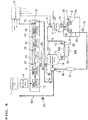
FIG. 4] FIG. 4 is a block diagram for illustrating rinsing of the entire drink supply piping with aseptic water in the cleaning and sterilization method according to the present invention. - [
FIG. 5] FIG. 5 is a block diagram for illustrating manufacture of a product by filling a bottle with a drink. - [
FIG. 6] FIG. 6 is a graph for illustrating a variation in temperature of the filling machine in the CIP, the SIP and the rinsing and a drink filling step in the cleaning and sterilization method according to the present invention. - [
FIG. 7] FIG. 7 is a graph for illustrating a variation in temperature of the filling machine in the CIP, the SIP and the rinsing and the drink filling step in a conventional cleaning and sterilization method. - [
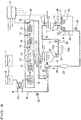
FIG. 8] FIG. 8 is a block diagram for illustrating a modification of the rinsing of the entire drink supply piping with aseptic water in the cleaning and sterilization method according to the present invention. - In the following, an embodiment of the present invention will be described with reference to the drawings.
- A configuration of a drink filling apparatus will be first described, and a method of cleaning and sterilizing the apparatus and a product filling method for the apparatus will then be described.
- As shown in
FIG. 1 , the drink filling apparatus includes apreparation unit 1 for a drink as a product and afilling machine 2 that fills a bottle 4 with the drink. Thepreparation unit 1 and fillingnozzles 2a in thefilling machine 2 are coupled to each other bydrink supply piping 7. Thefilling machine 2 is surrounded by anaseptic chamber 3. - The
preparation unit 1 prepares a drink such as tea or fruit juice by mixing ingredients in desired proportions. Thepreparation unit 1 is a well-known device and therefore will not be described in detail herein. - The
filling machine 2 includes a large number of fillingnozzles 2a arranged around a wheel (not shown), which rotates at high speed in a horizontal plane. As the wheel rotates, thefilling nozzles 2a rotate, and the drink is metered from thefilling nozzles 2a into bottles 4 traveling below thefilling nozzles 2a at a velocity adjusted to the circumferential velocity of the wheel. Thefilling machine 2 is also a well-known machine and therefore will not be described in detail herein. - In the drink filling apparatus, along the path of the
drink supply piping 7 from thepreparation unit 1 to thefilling machine 2, abalance tank 5, a heating sterilization part (hereinafter, referred to also as UHT: Ultra High-temperature) 18, amanifold valve 8, anaseptic surge tank 19, and ahead tank 11 are disposed in this order from upstream to downstream of the flow of the drink. - The
heating sterilization part 18 includes a first-stage heating portion 12, a second-stage heating portion 13, aholding tube 14, a first-stage cooling portion 15 and a second-stage cooling portion 16, for example. The drink or water supplied from thebalance tank 5 is gradually heated while fed from the first-stage heating portion 12 to the second-stage heating portion 13 until a target sterilization temperature is reached at an exit of the second-stage heating portion 13, kept at the sterilization temperature for a certain time in theholding tube 14, and then gradually cooled while fed from the first-stage cooling portion 15 to the second-stage cooling portion 16. The number of stages of heating portions or cooling portions can be increased or decreased as required. Theheating sterilization part 18 may include a homogenizer capable of automatic washing. The homogenizer is preferably disposed between the first-stage heating portion, in which the temperature of the content of the product is about 50 to 70°C, and the second-stage heating portion, in which the temperature of the content of the product is about 60 to 150°C, or between the first-stage cooling portion and the second-stage cooling portion. In the former case, a common homogenizer can be used. In the latter case, however, an aseptic homogenizer is needed. Theheating sterilization part 18 can be of any type, such as a shell-and-tube heat exchanger or a plate heat exchanger. Furthermore, not only the indirect heating method described above but also the direct heating method can be used. - The
balance tank 5, themanifold valve 8, theaseptic surge tank 19 and thehead tank 11 are well-known devices and therefore will not be described in detail herein. Theaseptic surge tank 19 and thehead tank 11 are provided with equipment to which aseptic air is supplied. - Next, a process path along which CIP and SIP are performed will be described. As shown by a bold line in
FIG. 2 , an upstream-side piping section 7a of thedrink supply piping 7, which extends from thebalance tank 5 to themanifold valve 8 through theheating sterilization part 18, is provided with an upstream-side feedback path 6a to form an upstream-side process path, which is a circulation path for the CIP or SIP. - As shown by a bold line in
FIG. 3 , a downstream-side piping section 7b, which extends from themanifold valve 8 to theaseptic surge tank 19, then to thehead tank 11, then to the fillingmachine 2 and then back to themanifold valve 8, is provided with a downstream-side feedback path 6b to form a downstream-side process path, which is a circulation path for the CIP or SIP. - The upstream-
side piping section 7a is provided withtemperature sensors 10 at positions including a position where the temperature is less likely to increase during the SIP. For example, thetemperature sensors 10 can be disposed at positions along the pipe line from the second-stage heating portion 13 in theheating sterilization part 18 to themanifold valve 8, such as positions in theheating sterilization part 18, a position at the outlet of the second-stage cooling portion 16, and a position at the inlet of themanifold valve 8. Thetemperature sensors 10 are disposed at these positions. Temperature information from thetemperature sensors 10 is transmitted to acontroller 17. - The
balance tank 5 can be any tank, such as an open tank for which the filling temperature is prescribed to be lower than 100°C or a tank that is a first class pressure vessel (Occupational Safety and Health Regulation Section (v)) to which a fluid at a temperature of 100°C or higher can be fed. When the open tank is used, a cooling unit is preferably provided on the upstream-side feedback path 6a between themanifold valve 8 and thebalance tank 5. - As shown by the bold line in
FIG. 3 , the downstream-side piping section 7b is also provided withtemperature sensors 10 at positions including a position where the temperature is less likely to increase during the SIP. For example, thetemperature sensors 10 can be disposed at positions along the pipe line from theaseptic surge tank 19 to the fillingnozzles 2a, such as a position in the vicinity of the outlet of theaseptic surge tank 19, a midway bent point, positions in the vicinities of the inlet and outlet of thehead tank 11, positions between a manifold 2b and the fillingnozzles 2a in the fillingmachine 2. Thetemperature sensors 10 are disposed at these positions. Temperature information from thetemperature sensors 10 is transmitted to thecontroller 17. - In the downstream-
side piping section 7b, acup 9 is provided for an opening of each fillingnozzle 2a in the fillingmachine 2 for the CIP or SIP, and thecup 9 can be brought closer to and separated from the fillingnozzle 2a. To perform the CIP or SIP, an actuator (not shown) joins eachcup 9 to the opening at the tip end of the fillingnozzle 2a in the fillingmachine 2 to connect a leading end of adrain tube 20 to the opening of the fillingnozzle 2a. - The
drink supply piping 7 can include various switching valves, liquid feeding pumps or other components in addition to themanifold valve 8 and the actuator (not shown), and these components are also controlled by thecontroller 17. - The CIP or SIP may not be separately performed for the upstream-side piping section and the downstream-side piping section, and the process path may be formed by the
drink supply piping 7 including thebalance tank 5, theheating sterilization part 18, themanifold valve 8, theaseptic surge tank 19, thehead tank 11 and the fillingmachine 2 and the circulation path from the fillingmachine 2 to thebalance tank 5. That is, the process path may be the circulation path including the upstream-side piping section 7a, the downstream-side piping section 7b, the downstream-side feedback path 6b and the upstream-side feedback path 6a. - Next, a cleaning and sterilization method for the drink filling apparatus described above, a method of transition from the CIP to the SIP, a method of rinsing, and a drink product manufacturing step will be described with reference to
FIGS. 2 to 7 . - When an operation button on a panel (not shown) of the
controller 17 is manipulated, the CIP is performed for each of the upstream-side piping section and the downstream-side piping section of thedrink supply piping 7 in a predetermined procedure. The CIP is performed by flowing an alkali cleaner that contains a mixture of water and an alkali agent such as caustic soda (sodium hydroxide), potassium hydroxide, sodium carbonate, sodium silicate, sodium phosphate, sodium hydrochloride, a surface active agent or a chelating agent (sequestering agent) such as sodium gluconate or ethylenediaminetetraacetic acid (EDTA) and is supplied from a cleaner supply source (not shown) through thedrink supply piping 7, the upstream-side feedback path 6a and the downstream-side feedback path 6b and then flowing an acid cleaner that contains a mixture of water and a nitrate-based or phosphate-based acid agent and is supplied from a cleaner supply source (not shown) through thedrink supply piping 7, the upstream-side feedback path 6a and the downstream-side feedback path 6b. - The alkali cleaner may be lithium carbonate, ammonium carbonate, magnesium carbonate, calcium carbonate, propylene carbonate or a mixture thereof. However, the alkali cleaner is not limited to those substances. For example, the alkali cleaner may be a bicarbonate such as sodium bicarbonate, potassium bicarbonate, lithium bicarbonate, ammonium bicarbonate, magnesium bicarbonate or calcium bicarbonate, a sesquicarbonate such as sodium sesquicarbonate, potassium sesquicarbonate or lithium sesquicarbonate, or a mixture thereof.
- The acid cleaner may not be the nitric acid or phosphoric acid described above but may also be hydrochloric acid, sulfuric acid, acetic acid, citric acid, lactic acid, formic acid, glycolic acid, methanesulfonic acid, sulfamic acid or a mixture thereof. However, the acid cleaner is not limited to those substances.
- The cleaners may contain various bleaching agents such as hypochlorite, hydrogen peroxide, peracetic acid, peroctanoic acid, persulfate, perborate, hydrosulfite or thiourea dioxide, or percarbonate, for example. The cleaners may further contain a water softener such as aluminosilicate or polycarboxylate, or an antiredeposition agent such as sodium phosphate, sodium polyacrylate or sodium carboxylate. Furthermore, the cleaners may contain an enzyme, a solvent, a fatty acid, a foam control agent, an active oxygen source or the like.
- The cleaners can be used in other sequences than the sequence described above in the CIP. For example, the alkali cleaner may be used after the acid cleaner is used, or the CIP may be performed by flowing only the acidic cleaner or the alkali cleaner.
- The CIP for the upstream-side process path is performed by circulating the cleaners supplied from the cleaner supply sources (not shown) through the upstream-side process path including the
balance tank 5, theheating sterilization part 18 and themanifold valve 8 provided in the upstream-side piping section 7a of thedrink supply piping 7 as shown inFIG. 2 . To activate the cleaners, theheating sterilization part 18 provided on the upstream-side piping section 7a heats the cleaners to a predetermined temperature (80°C, for example). The cleaners are constantly or intermittently supplied in a constant amount from the respective cleaner supply sources (not shown) and remove drink residues from the previous operation on the interior of thedrink supply piping 7 while circulating in thedrink supply piping 7. The cleaners may be discharged from the apparatus as appropriate. After the cleaners at a predetermined temperature are passed for a predetermined time, the CIP ends. The completion of the CIP is managed by thecontroller 17, and then transition to the SIP occurs. - The CIP for the downstream-side process path is performed by circulating the cleaners supplied from the cleaner supply sources (not shown) through the downstream-side process path including the
manifold valve 8, theaseptic surge tank 19, thehead tank 11 and the fillingmachine 2 provided along thedrink supply piping 7 as shown inFIG. 3 . To activate the cleaners, aheating unit 21 provided on the downstream-side piping section 7b heats the cleaners to a predetermined temperature (80°C, for example). The cleaners are constantly or intermittently supplied in a constant amount from the respective cleaner supply sources (not shown) and remove drink residues from the previous operation on the interior of thedrink supply piping 7 while circulating in thedrink supply piping 7. The cleaners may be discharged from the apparatus as appropriate. After the cleaners at a predetermined temperature are passed for a predetermined time, the CIP ends. The completion of the CIP is managed by thecontroller 17, and then transition to the SIP occurs. - Before the CIP for the downstream-side process path is performed, the
cups 9 are joined to the openings of the fillingnozzles 2a and thedrain tubes 20 are connected to the fillingnozzles 2a, thereby allowing the cleaners to circulate through the downstream-side feedback path 6b, which is the downstream-side process path. - When the CIP ends, the SIP is performed for each of the upstream-side process path and the downstream-side process path in a predetermined procedure. Before the SIP, as with the CIP, the
manifold valve 8 disconnects the upstream-side piping section 7a and the downstream-side piping section 7b from each other as required. - The SIP for the upstream-side process path and the SIP for the downstream-side process path can be performed in sequence or in parallel with each other.
- First, the SIP performed for the upstream-side process path will be described. The liquid feeding pump used for the CIP is not stopped, and while the cleaner used in the CIP is circulating in the upstream-side process path, the cleaner is heated to a required temperature for the SIP by the
heating sterilization part 18, and the SIP is achieved by the cleaner heated to the higher temperature circulating in the upstream-side process path. In this step, since the liquid feeding pump is not stopped, the temperature of theheating sterilization part 18 raised and set in the CIP does not decrease but is further raised to a temperature for the SIP. Thus, the temperature in the upstream-side piping section 7a including theheating sterilization part 18 does not decrease during the transition from the CIP to the SIP. - When the cleaner is flowing in the upstream-side process path, the
temperature sensors 10 disposed at different positions along the upstream-side piping section 7a transmit temperature information to thecontroller 17 at regular time intervals. In this embodiment, when the drink, which is a product liquid with which the bottle 4 is to be filled, has a pH of 4.6 or higher, a reference temperature Tr can be set at 121.1°C and the Z value can be set at 10°C as temperature conditions for sterilization. - The last cleaner used in the CIP is heated to the required temperature for the SIP in the
heating sterilization part 18, and when the temperature at each of the different positions along the upstream-side piping section 7a reaches 121.1°C, thecontroller 17 starts calculating the F value at the position according to the following formula.
is a fatality rate at the optional temperature T, Tr is a reference temperature (°C), and Z is a Z value (°C).) - When the minimum F value of the F values calculated according to the formula described above reaches a target value, it is determined that sterilization of the upstream-
side piping section 7a is completed. The sterilization method is not limited to the sterilization method based on the calculated F value described above but may be a known sterilization method based on temperature and time, for example. - In the formula for calculating the F value described above, the reference temperature Tr and the Z value can be changed according to the kind of the drink, which is a product liquid. For example, when the pH of the product liquid is equal to or higher than 4 and lower than 4.6, the reference temperature Tr can be 85°C, and the Z value can be 7.8°C. When the pH of the product liquid is lower than 4, the reference temperature Tr can be 65°C, and the Z value can be 5°C. The values to be substituted into the formula described above can be changed as appropriate according to the ease of development of microorganisms, the temperature during distribution or the like of the product liquid, such as tea, mineral water or a chilled drink. Thus, the required temperature for SIP varies with the kind of the drink to be handled next. Therefore, with regard to the transition from the CIP process to the SIP process, if the temperature required for SIP may be low, the CIP may be performed at a higher temperature than the SIP.
- The SIP for the upstream-
side piping section 7a may not be performed in succession to the CIP. The product also may not be manufactured immediately after the SIP. The drink filling apparatus may enter into a standby state for the subsequent manufacturing operation after the upstream-side piping section 7a is sterilized by aseptic water sterilized to have a sterilization value equal to or higher than that required for the drink to be manufactured next to prepare to feed the aseptic water to the downstream-side piping section 7b. - When or before the SIP for the upstream-
side piping section 7a is started, the SIP for the downstream-side process path including theaseptic surge tank 19 is started. - Next, the SIP performed for the downstream-side process path will be described. The liquid feeding pump used for the CIP is not stopped, and while the cleaner used in the CIP is circulating in the downstream-side process path, the cleaner is heated to a required temperature for the SIP by the
heating unit 21, and the SIP is achieved by the cleaner circulating in the downstream-side process path. In this step, since the liquid feeding pump is not stopped, the temperature in the downstream-side piping section 7b raised in the CIP does not decrease, and the cleaner is heated to the required temperature for the SIP. Thus, unlike the conventional method shown inFIG. 7 , the temperature in the downstream-side piping section 7b including the fillingmachine 2 does not decrease during the transition from the CIP to the SIP. That is, as shown inFIG. 6 , the temperature in the downstream-side piping section 7b including the fillingmachine 2 does not decrease during the transition from the CIP to the SIP. - When the cleaner is flowing in the downstream-side process path, the
temperature sensors 10 disposed at different positions along the downstream-side piping section 7b including the fillingnozzles 2a transmit temperature information to thecontroller 17 at regular time intervals. In this embodiment, when the drink, which is a product liquid with which the bottle 4 is to be filled, has a pH of 4.6 or higher, the reference temperature Tr can be set at 121.1°C and the Z value can be set at 10°C as temperature conditions for sterilization. - The last cleaner used in the CIP is heated to the required temperature for the SIP by the
heating unit 21, and when the temperature at each of the different positions along the downstream-side piping section 7b reaches 121.1°C, thecontroller 17 starts calculating the F value at the position according to the following formula.
is a fatality rate at the optional temperature T, Tr is a reference temperature (°C), and Z is a Z value (°C).) - When the minimum F value of the F values calculated according to the formula described above reaches a target value, it is determined that sterilization of the downstream-
side piping section 7b is completed. The sterilization method is not limited to the sterilization method based on the calculated F value described above but may be a known sterilization method based on temperature and time, for example. - In the formula for calculating the F value described above, the reference temperature Tr and the Z value can be changed according to the kind of the drink, which is a product liquid. For example, when the pH of the product liquid is equal to or higher than 4 and lower than 4.6, the reference temperature Tr can be 85°C, and the Z value can be 7.8°C. When the pH of the product liquid is lower than 4, the reference temperature Tr can be 65°C, and the Z value can be 5°C. The values to be substituted into the formula described above can be changed as appropriate according to the ease of development of microorganisms, the temperature during distribution or the like of the product liquid, such as tea, mineral water or a chilled drink. Thus, the required temperature for SIP varies with the kind of the drink to be handled next. Therefore, with regard to the transition from the CIP process to the SIP process, if the temperature required for SIP may be low, the CIP may be performed at a higher temperature than the SIP.
- Under a condition that the temperature in the SIP is higher than 100°C, the downstream-side process path may be cooled with aseptic air after the SIP is completed. In this step, the downstream-side process path is cooled by supplying aseptic air (or nitrogen) filtered and sterilized through a sterilization filter until the temperature in the
aseptic surge tank 19 and thehead tank 11 is lower than 100°C. In this step, at the same time, a coolant such as water may be supplied to jackets of theaseptic surge tank 19 and thehead tank 11 to cool the downstream-side process path. - After the SIP is completed, the cleaner used in the SIP is discharged from the upstream-side process path and the downstream-side process path at the same time or in sequence, and the cleaner remaining in the
drink supply piping 7, the upstream-side feedback path 6a and the downstream-side feedback path 6b is washed away with aseptic water. The upstream-side process path may be left unrinsed until the SIP for the downstream-side process path is completed, and after the SIP for the downstream-side process path is completed, the upstream-side process path and the downstream-side process path may be coupled to each other and rinsed at the same time. Alternatively, the upstream-side process path may be first rinsed and left with aseptic water circulating therein, and after the SIP for the downstream-side process path is completed, the upstream-side process path and the downstream-side process path may be coupled to each other to feed the aseptic water in the upstream-side process path to the downstream-side process path, thereby rinsing the downstream-side process path. - The CIP and SIP are performed by circulating the cleaners in each of the upstream-side process path of the
drink supply piping 7 including thebalance tank 5, theheating sterilization part 18 and themanifold valve 8 and the downstream-side process path of thedrink supply piping 7 including themanifold valve 8, theaseptic surge tank 19, thehead tank 11 and the fillingmachine 2. However, as shown inFIG. 4 , rinsing of the interior of thedrink supply piping 7 with aseptic water is performed by flowing the aseptic water to the upstream-side feedback path 6a through theheating sterilization part 18, themanifold valve 8, theaseptic surge tank 19, thehead tank 11, the fillingmachine 2, the downstream-side feedback path 6b and themanifold valve 8 to wash the cleaner away, and discharging the rinsing liquid from the drink filling apparatus. - The aseptic water is produced by supplying water or pure water into the
balance tank 5 and heating and sterilizing the water or pure water under a sterilization condition that is comparable to or stricter than the sterilization condition for the drink to be filled next in theheating sterilization part 18. Since the aseptic water is produced under the sterilization condition comparable to that for the drink to be filled next, the sterilization condition of theheating sterilization part 18 is stabilized and the downstream-side piping section 7b is cooled while the rinsing is performed, and the drink can be sterilized and the product can be manufactured immediately after the rinsing is completed. -
FIG. 6 is a graph showing a variation in temperature of the fillingmachine 2 in the CIP, the SIP and the rinsing of the downstream-side piping section 7b and a drink filling step (manufacturing step). After the CIP, the cleaner is heated to the required temperature for the SIP. After the SIP is completed, the temperature decreases as the rinsing proceeds. When the rinsing is completed and the temperature of the fillingmachine 2 is settled at room temperature, the bottles 4 can be immediately aseptically filled with the drink that has been sterilized and settled at room temperature. Neither time nor energy is wasted between the CIP and the manufacturing step of filling the bottles 4 with the drink. -
FIG. 7 shows a variation in temperature of the fillingmachine 2 in the CIP, the SIP, the rinsing and the drink filling step (manufacturing step) in the conventional cleaning and sterilization method. The cleaner is heated to perform the CIP, and then rinsing with water or pure water that is not aseptic water is performed to wash the cleaner away. The water used for the rinsing is water and therefore is at room temperature, so that the fillingmachine 2, which has been at a higher temperature because of the CIP with the heated cleaner, is cooled by the rinsing water and substantially settled at room temperature when the rinsing is completed. After that, heated water or heated steam is circulated for the SIP and heats the fillingmachine 2 again. The fillingmachine 2 thus heated in the SIP needs to be cooled in order to aseptically fill the bottles 4 with the drink, and aseptic air or water is flowed to cool the fillingmachine 2. In this way, the conventional method requires longer times than the present invention to heat thedrink supply piping 7 including theheating sterilization part 18 and the fillingmachine 2 that is cooled in the rinsing and to cool the section of thedrink supply piping 7 that is downstream of the first-stage cooling portion 15 of theheating sterilization part 18 after the SIP. In addition, since heating and cooling are each performed twice, a larger amount of energy is required compared with the method shown inFIG. 6 . - Furthermore, as shown in
FIG. 8 , aheat exchanger 24 may be arranged between theheating sterilization part 18 and the balance tank 5 (or at a position preceding the balance tank 5) as required. Theheat exchanger 24 can exchange heat between the cleaner for cleaning or sterilizing the interior of thedrink supply piping 7 raised in temperature in theheating sterilization part 18 or the water for rinsing the interior of thedrink supply piping 7 raised in temperature in theheating sterilization part 18 and the water or pure water at a lower temperature supplied from thebalance tank 5, thereby raising the temperature of the water or pure water supplied from thebalance tank 5 to theheating sterilization part 18. In this way, theheat exchanger 24 can reduce the burden on theheating sterilization part 18 when raising the temperature of the water or pure water and improve the thermal efficiency. - Immediately after the rinsing is started, the first-
stage heating portion 12 and the second-stage heating portion 13, which have been heating the cleaner for the SIP for the upstream-side process path, can heat the water or pure water to a set temperature. However, the first-stage cooling portion 15 and the second-stage cooling portion 16, which have not been operating, and whose flow path is under the temperature condition for the SIP, takes some time to stabilize the cooling. However, the cooling is stabilized while the rinsing is performed. Once the cleaner is completely removed, the rinsing step can be ended, the drink to be filled next can be immediately sterilized and cooled, and the bottles 4 can be filled with the drink. - When the cleaner in the upstream-side process path and the downstream-side process path is removed with the aseptic water, and the cleaner in the filling
nozzles 2a of the fillingmachine 2 is completely replaced by the aseptic water, the aseptic water is fed from the upstream-side piping section 7a to the upstream-side feedback path 6a through themanifold valve 8 and circulated in the upstream-side process path. Feeding of the aseptic water to the downstream-side piping section 7b is stopped. Furthermore, at the same time or after that, aseptic air is supplied into thedrink supply piping 7 including theaseptic surge tank 19, thehead tank 11, the upstream-side piping section 7a and the downstream-side piping section 7b while removing the aseptic water remaining in theaseptic surge tank 19, thehead tank 11 and the downstream-side piping section 7b, thereby keeping the interior of thedrink supply piping 7 including theaseptic surge tank 19, thehead tank 11, the upstream-side piping section 7a and the downstream-side piping section 7b, in which the SIP has been performed, at a positive pressure and maintaining the aseptic condition in thedrink supply piping 7. Furthermore, after the rinsing is completed, the actuator (not shown) removes thecups 9 from the openings of the fillingnozzles 2a. - The downstream-
side piping section 7b of thedrink supply piping 7 is cooled by being rinsed with the aseptic water. However, in order to prevent the pressure in theaseptic surge tank 19 and thehead tank 11 from decreasing due to rapid cooling, the downstream-side piping section 7b of thedrink supply piping 7 is preferably cooled under pressure by supplying aseptic air into the tanks. After the temperature of the tanks is lowered to about 30°C to 90°C, and the cooling is completed, the aseptic water remaining in the tanks and the piping is blown off by aseptic air while maintaining the positive pressure, and the drink is received. The tanks may be quickly cooled by supplying water or chiller water to jackets of the tanks in parallel with the cooling process by the rinsing. If it is difficult to discharge the aseptic water from thedrink supply piping 7, the drink can also be fed into thedrink supply piping 7, and any diluted drink alone can be discharged from the fillingmachine 2 before the manufacture is started. - If the drink to be filled next is a carbonated drink, the aseptic water is fed from a vicinity of the
aseptic surge tank 19 to thehead tank 11 and the fillingnozzles 2a through a carbonated drink line (not shown). On the carbonated drink line, the aseptic water is further cooled (to 1 to 5°C) by chiller water. Thus, the remaining heat from the SIP can be completely removed, and foaming of the carbon dioxide gas can be reduced during filling. - After the rinsing ends, the drink flowing from the
heating sterilization part 18 through the upstream-side piping section 7a is stored in theaseptic surge tank 19, and a manufacturing step of filling the bottles 4 with the drink flowing therefrom through the downstream-side piping section 7b is started. - As shown by a bold line in
FIG. 5 , in the manufacturing step, the drink prepared in thepreparation unit 1 flows to the interior of the fillingmachine 2 through the sterilized upstream-side piping section 7a and downstream-side piping section 7b of thedrink supply piping 7, and the bottles 4 as containers are filled with the drink through the fillingnozzles 2a in the fillingmachine 2. The bottles 4 filled with the drink are capped by a capper (not shown) and then fed out of the drink filling machine. - The
drink supply piping 7 is preferably provided with a filtering device that filters out foreign matters in the product or product residues to be removed in the CIP. The filtering device includes afirst filtering device 22a and asecond filtering device 22b arranged in parallel with each other, and thefirst filtering device 22a and thesecond filtering device 22b include a filtering member formed by a metal filter, such as a stainless steel filter. The filtering device further includes switchingdevices 23 that automatically or manually switch between thefirst filtering device 22a and thesecond filtering device 22b. - The
first filtering device 22a and thesecond filtering device 22b are preferably metal filters such as stainless steel filters and preferably differ in mesh fineness (mesh size). Preferably, for example, thefirst filtering device 22a includes a metal filter of 100 to 400 mesh capable of removing finer foreign matters, and thesecond filtering device 22b includes a rougher metal filter of 10 to 100 mesh capable of appropriately allowing flesh or pulp in the product to pass therethrough. By using filtering devices of different counts for thefirst filtering device 22a and thesecond filtering device 22b as described above, foreign matters can be appropriately removed from each individual product to be manufactured. - In addition, the
switching devices 23 allow switching between thefirst filtering device 22a and thesecond filtering device 22b. Since theswitching devices 23 are provided, while thefirst filtering device 22a is being used for filling with the product as shown inFIG. 5 , a cleaning step for thesecond filtering device 22b can be performed to remove foreign matters from thesecond filtering device 22b. Thus, during manufacture of the product, the filtering device can be efficiently cleaned and inspected. After the cleaning and inspection of the filters, the CIP or the SIP can be separately performed. Theswitching devices 23 can be set to feed liquid to both thefirst filtering device 22a and thesecond filtering device 22b. In that case, the CIP or the SIP for both thefirst filtering device 22a and thesecond filtering device 22b can be performed at the same time. - As shown in
FIG. 1 , for example, the filtering device may be disposed between the second-stage cooling portion (final cooling portion) 16 and themanifold valve 8, rather than being disposed between theaseptic surge tank 19 and thehead tank 11. A plurality of filtering devices arranged in parallel with each other may be provided. The filtering device may be disposed at different positions, for example, at a position upstream of thebalance tank 5 or at the tip ends of the fillingnozzles 2a. - As described above, the
first filtering device 22a and thesecond filtering device 22b are arranged in parallel with each other in the filtering device. Therefore, for example, filtering of the product can be performed by thefirst filtering device 22a when the product is manufactured in the first manufacturing step, and can be performed by thesecond filtering device 22b when the product is manufactured in the second manufacturing step. In that case, while the product is being manufactured, the filtering device that is not used for filtering of the product is preferably subjected to a cleaning step of removing remaining foreign matters from the manufacturing step and an inspection operation of checking that the product does not contain rubber or metal foreign matters such as a gasket residue. By performing the cleaning operation and the inspection operation during manufacture of the product as described above, a cleaned filtering device can always be used after transition from the first manufacturing step to the second manufacturing step, and the operability of the product filling apparatus is improved. - Although the present invention is configured as described above, the present invention is not limited to the embodiment described above, and various modifications can be made within the scope of the spirit of the present invention.
-
- 2
- filling machine
- 6a
- upstream-side feedback path
- 6b
- downstream-side feedback path
- 7
- drink supply piping
- 7a
- upstream-side piping section
- 7b
- downstream-side piping section
- 18
- heating sterilization part
Claims (3)
- A method of cleaning and sterilizing a drink filling apparatus that includes drink supply piping that feeds a drink sterilized in a heating sterilization part into a filling machine, the method comprising performing a cleaning in place (CIP), in which a cleaner is circulated in the drink supply piping to remove a drink residue or the like on an interior of the drink supply piping, raising a temperature of the cleaner to a temperature required for a sterilizing in place (SIP), which is performed in succession to the CIP to sterilize the interior of the drink supply piping, from an early stage or middle stage of the CIP, then performing the SIP for the interior of the drink supply piping, and washing the cleaner away with aseptic water,
wherein the aseptic water is heated and sterilized in the heating sterilization part. - The method of cleaning and sterilizing a drink filling apparatus according to Claim 1, wherein the CIP and the SIP are performed by circulating a cleaner in each of an upstream-side process path of the drink supply piping including a balance tank, the heating sterilization part and a manifold valve and a downstream-side process path of the drink supply piping including the manifold valve, an aseptic surge tank, a head tank and the filling machine, and rinsing of the interior of the drink supply piping with the aseptic water is performed by flowing to the heating sterilization part, the manifold valve, the aseptic surge tank, the head tank, the filling machine and the manifold valve and discharging from the drink filling apparatus.
- The method of cleaning and sterilizing a drink filling apparatus according to Claim 1 or 2, wherein a condition of sterilization of the aseptic water in the heating sterilization part is comparable to or stricter than a condition of sterilization of the drink to be filled next.
Applications Claiming Priority (2)
| Application Number | Priority Date | Filing Date | Title |
|---|---|---|---|
| JP2018004863A JP6696516B2 (en) | 2018-01-16 | 2018-01-16 | Beverage filling machine cleaning and sterilization method |
| PCT/JP2019/000721 WO2019142742A1 (en) | 2018-01-16 | 2019-01-11 | Method for cleaning and sterilizing beverage filling device |
Publications (3)
| Publication Number | Publication Date |
|---|---|
| EP3741721A1 true EP3741721A1 (en) | 2020-11-25 |
| EP3741721A4 EP3741721A4 (en) | 2022-02-23 |
| EP3741721B1 EP3741721B1 (en) | 2026-03-04 |
Family
ID=67301022
Family Applications (1)
| Application Number | Title | Priority Date | Filing Date |
|---|---|---|---|
| EP19741154.9A Active EP3741721B1 (en) | 2018-01-16 | 2019-01-11 | Method for cleaning and sterilizing beverage filling device |
Country Status (5)
| Country | Link |
|---|---|
| US (1) | US11708257B2 (en) |
| EP (1) | EP3741721B1 (en) |
| JP (1) | JP6696516B2 (en) |
| CN (1) | CN111629989B (en) |
| WO (1) | WO2019142742A1 (en) |
Cited By (2)
| Publication number | Priority date | Publication date | Assignee | Title |
|---|---|---|---|---|
| EP4256952A1 (en) * | 2022-04-07 | 2023-10-11 | Tetra Laval Holdings & Finance S.A. | A cleaning in place unit, a cleaning in place system and a method thereof |
| WO2025146569A1 (en) * | 2024-01-07 | 2025-07-10 | Mhd Dib Almanfoush Emad Eddin | A clean-in-place system for volumetric filling machines and a method thereof |
Families Citing this family (14)
| Publication number | Priority date | Publication date | Assignee | Title |
|---|---|---|---|---|
| JP6760343B2 (en) * | 2018-08-31 | 2020-09-23 | 大日本印刷株式会社 | Aseptic filling machine and its purification method |
| JP7434749B2 (en) * | 2019-08-14 | 2024-02-21 | 大日本印刷株式会社 | Sterilization method and sterilization device in sterile water supply piping of aseptic filling machine |
| DE102019132749A1 (en) * | 2019-12-03 | 2021-06-10 | Krones Ag | Device for filling a container with CIP cleaning |
| JP7070816B2 (en) * | 2020-05-15 | 2022-05-18 | 大日本印刷株式会社 | Cleaning and sterilization method of aseptic filling machine and aseptic filling machine |
| JP7070628B2 (en) | 2020-09-23 | 2022-05-18 | 大日本印刷株式会社 | Cleaning and sterilization method of aseptic filling machine and aseptic filling machine |
| DE102020130740A1 (en) * | 2020-11-20 | 2022-05-25 | Krones Aktiengesellschaft | Device for filling a container with a filling product |
| JP7268671B2 (en) | 2020-12-25 | 2023-05-08 | 大日本印刷株式会社 | Cleaning and sterilization method for carbon dioxide gas line of aseptic filling machine and aseptic filling machine |
| JP7302588B2 (en) * | 2020-12-25 | 2023-07-04 | 大日本印刷株式会社 | Beverage filling system and CIP processing method |
| JP2023020621A (en) * | 2021-07-30 | 2023-02-09 | 岩井機械工業株式会社 | Sterilization device |
| CN115338200B (en) * | 2022-05-24 | 2023-08-29 | 江苏新美星包装机械股份有限公司 | CIP cleaning system for UHT system |
| CN115351017B (en) * | 2022-09-01 | 2025-03-28 | 东莞建晖纸业有限公司 | A device and method for removing crust inside pipeline of starch continuous steaming system |
| CN116036319A (en) * | 2022-12-01 | 2023-05-02 | 椰枫堂(广州)生物科技有限公司 | A tubular sterilization process and its application |
| WO2026020068A1 (en) * | 2024-07-19 | 2026-01-22 | Siemens Healthcare Diagnostics Inc. | Method of pasteurizing the water supply of laboratory diagnostic instruments |
| CN119926923B (en) * | 2025-04-08 | 2025-06-17 | 浙江大学长三角智慧绿洲创新中心 | Method for cleaning water supply pipeline by double-layer annular modified ice slurry |
Family Cites Families (14)
| Publication number | Priority date | Publication date | Assignee | Title |
|---|---|---|---|---|
| JP2007022600A (en) * | 2005-07-19 | 2007-02-01 | Toyo Seikan Kaisha Ltd | Method for cleaning and sterilizing pipe system of filling machine in food filling system |
| JP4895697B2 (en) * | 2006-06-15 | 2012-03-14 | 株式会社日本キャンパック | Beverage filling equipment cleaning equipment |
| CN101164418B (en) * | 2006-10-21 | 2011-07-20 | 内蒙古伊利实业集团股份有限公司 | Ultra-high temperature sterilization machine cleaning technology |
| JP5838720B2 (en) * | 2011-10-25 | 2016-01-06 | 大日本印刷株式会社 | Sterilization treatment line and purification method thereof |
| CN103303852A (en) * | 2012-03-13 | 2013-09-18 | 山东工大机械有限公司 | Full-automatic double-cylinder equal difference pressure asepsis filling and sealing machine |
| EP3620426B1 (en) * | 2012-11-16 | 2023-03-01 | Dai Nippon Printing Co., Ltd. | Apparatus for filling a drink comprising means for cleaning and sterilizing the apparatus |
| EP3120940B1 (en) | 2012-12-21 | 2021-11-17 | Dai Nippon Printing Co., Ltd. | Beverage filling method |
| CN103892402A (en) * | 2012-12-30 | 2014-07-02 | 上海沃迪自动化装备股份有限公司 | Pilot plant test sterilization system |
| JP5574025B1 (en) * | 2013-06-25 | 2014-08-20 | 大日本印刷株式会社 | Sterilization method and apparatus for beverage supply system piping |
| JP6230120B2 (en) * | 2014-03-18 | 2017-11-15 | 三菱重工機械システム株式会社 | Beverage filling system |
| JP6131999B1 (en) * | 2015-11-18 | 2017-05-24 | 大日本印刷株式会社 | Aseptic filling apparatus and purification method thereof |
| MY191902A (en) * | 2015-09-17 | 2022-07-18 | Dainippon Printing Co Ltd | Aseptic filling apparatus and method of decontaminating the same |
| CN108290729B (en) * | 2015-12-22 | 2020-10-09 | 大日本印刷株式会社 | Sterilization conversion method and product filling device |
| JP6617758B2 (en) * | 2017-10-04 | 2019-12-11 | 大日本印刷株式会社 | Cleaning and sterilizing method for beverage filling equipment |
-
2018
- 2018-01-16 JP JP2018004863A patent/JP6696516B2/en active Active
-
2019
- 2019-01-11 CN CN201980008553.2A patent/CN111629989B/en active Active
- 2019-01-11 EP EP19741154.9A patent/EP3741721B1/en active Active
- 2019-01-11 US US16/958,871 patent/US11708257B2/en active Active
- 2019-01-11 WO PCT/JP2019/000721 patent/WO2019142742A1/en not_active Ceased
Cited By (3)
| Publication number | Priority date | Publication date | Assignee | Title |
|---|---|---|---|---|
| EP4256952A1 (en) * | 2022-04-07 | 2023-10-11 | Tetra Laval Holdings & Finance S.A. | A cleaning in place unit, a cleaning in place system and a method thereof |
| WO2023194070A1 (en) * | 2022-04-07 | 2023-10-12 | Tetra Laval Holdings & Finance S.A. | A cleaning in place unit, a cleaning in place system and a method thereof |
| WO2025146569A1 (en) * | 2024-01-07 | 2025-07-10 | Mhd Dib Almanfoush Emad Eddin | A clean-in-place system for volumetric filling machines and a method thereof |
Also Published As
| Publication number | Publication date |
|---|---|
| CN111629989A (en) | 2020-09-04 |
| JP2019123526A (en) | 2019-07-25 |
| US20200339401A1 (en) | 2020-10-29 |
| US11708257B2 (en) | 2023-07-25 |
| CN111629989B (en) | 2022-08-30 |
| JP6696516B2 (en) | 2020-05-20 |
| WO2019142742A1 (en) | 2019-07-25 |
| EP3741721A4 (en) | 2022-02-23 |
| EP3741721B1 (en) | 2026-03-04 |
Similar Documents
| Publication | Publication Date | Title |
|---|---|---|
| EP3741721B1 (en) | Method for cleaning and sterilizing beverage filling device | |
| EP3693329B1 (en) | Method for cleaning and sterilizing beverage filling device | |
| US11034566B2 (en) | Sterilization process transition method, product filling apparatus, and method and apparatus of cleaning and sterilizing the product filling apparatus | |
| JP7116036B2 (en) | Method and device for cleaning and sterilizing beverage filling equipment | |
| JP7709404B2 (en) | Method for cleaning and sterilizing aseptic filling machines and aseptic filling machines | |
| JP7373431B2 (en) | Beverage filling equipment and cleaning and sterilization methods for beverage filling equipment | |
| JP7513153B2 (en) | Method for cleaning and sterilizing aseptic filling machines and aseptic filling machines | |
| JP2020023369A (en) | Cleaning and sterilization method for beverage filling equipment |
Legal Events
| Date | Code | Title | Description |
|---|---|---|---|
| STAA | Information on the status of an ep patent application or granted ep patent |
Free format text: STATUS: THE INTERNATIONAL PUBLICATION HAS BEEN MADE |
|
| PUAI | Public reference made under article 153(3) epc to a published international application that has entered the european phase |
Free format text: ORIGINAL CODE: 0009012 |
|
| STAA | Information on the status of an ep patent application or granted ep patent |
Free format text: STATUS: REQUEST FOR EXAMINATION WAS MADE |
|
| 17P | Request for examination filed |
Effective date: 20200716 |
|
| AK | Designated contracting states |
Kind code of ref document: A1 Designated state(s): AL AT BE BG CH CY CZ DE DK EE ES FI FR GB GR HR HU IE IS IT LI LT LU LV MC MK MT NL NO PL PT RO RS SE SI SK SM TR |
|
| AX | Request for extension of the european patent |
Extension state: BA ME |
|
| DAV | Request for validation of the european patent (deleted) | ||
| DAX | Request for extension of the european patent (deleted) | ||
| TPAC | Observations filed by third parties |
Free format text: ORIGINAL CODE: EPIDOSNTIPA |
|
| REG | Reference to a national code |
Ref country code: DE Ref country code: DE Ref legal event code: R079 Ref document number: 602019082069 Country of ref document: DE Free format text: PREVIOUS MAIN CLASS: B67C0003000000 Ipc: A61L0002180000 |
|
| A4 | Supplementary search report drawn up and despatched |
Effective date: 20220120 |
|
| RIC1 | Information provided on ipc code assigned before grant |
Ipc: B67C 3/00 20060101ALI20220114BHEP Ipc: B08B 9/032 20060101ALI20220114BHEP Ipc: A61L 2/04 20060101ALI20220114BHEP Ipc: A61L 2/18 20060101AFI20220114BHEP |
|
| TPAC | Observations filed by third parties |
Free format text: ORIGINAL CODE: EPIDOSNTIPA |
|
| TPAC | Observations filed by third parties |
Free format text: ORIGINAL CODE: EPIDOSNTIPA |
|
| TPAC | Observations filed by third parties |
Free format text: ORIGINAL CODE: EPIDOSNTIPA |
|
| STAA | Information on the status of an ep patent application or granted ep patent |
Free format text: STATUS: EXAMINATION IS IN PROGRESS |
|
| 17Q | First examination report despatched |
Effective date: 20241204 |
|
| GRAP | Despatch of communication of intention to grant a patent |
Free format text: ORIGINAL CODE: EPIDOSNIGR1 |
|
| STAA | Information on the status of an ep patent application or granted ep patent |
Free format text: STATUS: GRANT OF PATENT IS INTENDED |
|
| INTG | Intention to grant announced |
Effective date: 20251006 |
|
| GRAS | Grant fee paid |
Free format text: ORIGINAL CODE: EPIDOSNIGR3 |
|
| GRAA | (expected) grant |
Free format text: ORIGINAL CODE: 0009210 |
|
| STAA | Information on the status of an ep patent application or granted ep patent |
Free format text: STATUS: THE PATENT HAS BEEN GRANTED |
|
| AK | Designated contracting states |
Kind code of ref document: B1 Designated state(s): AL AT BE BG CH CY CZ DE DK EE ES FI FR GB GR HR HU IE IS IT LI LT LU LV MC MK MT NL NO PL PT RO RS SE SI SK SM TR |
|
| REG | Reference to a national code |
Ref country code: CH Ref legal event code: F10 Free format text: ST27 STATUS EVENT CODE: U-0-0-F10-F00 (AS PROVIDED BY THE NATIONAL OFFICE) Effective date: 20260304 Ref country code: GB Ref legal event code: FG4D |
|
| REG | Reference to a national code |
Ref country code: DE Ref legal event code: R096 Ref document number: 602019082069 Country of ref document: DE |
|
| REG | Reference to a national code |
Ref country code: IE Ref legal event code: FG4D |
|
| PG25 | Lapsed in a contracting state [announced via postgrant information from national office to epo] |
Ref country code: RS Free format text: LAPSE BECAUSE OF FAILURE TO SUBMIT A TRANSLATION OF THE DESCRIPTION OR TO PAY THE FEE WITHIN THE PRESCRIBED TIME-LIMIT Effective date: 20260604 |
|
| PG25 | Lapsed in a contracting state [announced via postgrant information from national office to epo] |
Ref country code: ES Free format text: LAPSE BECAUSE OF FAILURE TO SUBMIT A TRANSLATION OF THE DESCRIPTION OR TO PAY THE FEE WITHIN THE PRESCRIBED TIME-LIMIT Effective date: 20260304 |
|
| REG | Reference to a national code |
Ref country code: NL Ref legal event code: MP Effective date: 20260304 |
|
| PG25 | Lapsed in a contracting state [announced via postgrant information from national office to epo] |
Ref country code: PL Free format text: LAPSE BECAUSE OF FAILURE TO SUBMIT A TRANSLATION OF THE DESCRIPTION OR TO PAY THE FEE WITHIN THE PRESCRIBED TIME-LIMIT Effective date: 20260304 |
|
| PG25 | Lapsed in a contracting state [announced via postgrant information from national office to epo] |
Ref country code: GR Free format text: LAPSE BECAUSE OF FAILURE TO SUBMIT A TRANSLATION OF THE DESCRIPTION OR TO PAY THE FEE WITHIN THE PRESCRIBED TIME-LIMIT Effective date: 20260605 |
|
| REG | Reference to a national code |
Ref country code: LT Ref legal event code: MG9D |
|
| PG25 | Lapsed in a contracting state [announced via postgrant information from national office to epo] |
Ref country code: LT Free format text: LAPSE BECAUSE OF FAILURE TO SUBMIT A TRANSLATION OF THE DESCRIPTION OR TO PAY THE FEE WITHIN THE PRESCRIBED TIME-LIMIT Effective date: 20260304 |
|
| PG25 | Lapsed in a contracting state [announced via postgrant information from national office to epo] |
Ref country code: NO Free format text: LAPSE BECAUSE OF FAILURE TO SUBMIT A TRANSLATION OF THE DESCRIPTION OR TO PAY THE FEE WITHIN THE PRESCRIBED TIME-LIMIT Effective date: 20260604 |
|
| PG25 | Lapsed in a contracting state [announced via postgrant information from national office to epo] |
Ref country code: FI Free format text: LAPSE BECAUSE OF FAILURE TO SUBMIT A TRANSLATION OF THE DESCRIPTION OR TO PAY THE FEE WITHIN THE PRESCRIBED TIME-LIMIT Effective date: 20260304 |
|
| PG25 | Lapsed in a contracting state [announced via postgrant information from national office to epo] |
Ref country code: HR Free format text: LAPSE BECAUSE OF FAILURE TO SUBMIT A TRANSLATION OF THE DESCRIPTION OR TO PAY THE FEE WITHIN THE PRESCRIBED TIME-LIMIT Effective date: 20260304 |
|
| PG25 | Lapsed in a contracting state [announced via postgrant information from national office to epo] |
Ref country code: LV Free format text: LAPSE BECAUSE OF FAILURE TO SUBMIT A TRANSLATION OF THE DESCRIPTION OR TO PAY THE FEE WITHIN THE PRESCRIBED TIME-LIMIT Effective date: 20260304 |
|
| PG25 | Lapsed in a contracting state [announced via postgrant information from national office to epo] |
Ref country code: BG Free format text: LAPSE BECAUSE OF FAILURE TO SUBMIT A TRANSLATION OF THE DESCRIPTION OR TO PAY THE FEE WITHIN THE PRESCRIBED TIME-LIMIT Effective date: 20260304 |