EP3741687A1 - Individual packaging device for tablets - Google Patents
Individual packaging device for tablets Download PDFInfo
- Publication number
- EP3741687A1 EP3741687A1 EP19763789.5A EP19763789A EP3741687A1 EP 3741687 A1 EP3741687 A1 EP 3741687A1 EP 19763789 A EP19763789 A EP 19763789A EP 3741687 A1 EP3741687 A1 EP 3741687A1
- Authority
- EP
- European Patent Office
- Prior art keywords
- tray
- tablet
- tablets
- unit
- packaging
- Prior art date
- Legal status (The legal status is an assumption and is not a legal conclusion. Google has not performed a legal analysis and makes no representation as to the accuracy of the status listed.)
- Granted
Links
Images












Classifications
-
- B—PERFORMING OPERATIONS; TRANSPORTING
- B65—CONVEYING; PACKING; STORING; HANDLING THIN OR FILAMENTARY MATERIAL
- B65B—MACHINES, APPARATUS OR DEVICES FOR, OR METHODS OF, PACKAGING ARTICLES OR MATERIALS; UNPACKING
- B65B43/00—Forming, feeding, opening or setting-up containers or receptacles in association with packaging
- B65B43/42—Feeding or positioning bags, boxes, or cartons in the distended, opened, or set-up state; Feeding preformed rigid containers, e.g. tins, capsules, glass tubes, glasses, to the packaging position; Locating containers or receptacles at the filling position; Supporting containers or receptacles during the filling operation
-
- B—PERFORMING OPERATIONS; TRANSPORTING
- B65—CONVEYING; PACKING; STORING; HANDLING THIN OR FILAMENTARY MATERIAL
- B65B—MACHINES, APPARATUS OR DEVICES FOR, OR METHODS OF, PACKAGING ARTICLES OR MATERIALS; UNPACKING
- B65B5/00—Packaging individual articles in containers or receptacles, e.g. bags, sacks, boxes, cartons, cans, jars
- B65B5/10—Filling containers or receptacles progressively or in stages by introducing successive articles, or layers of articles
- B65B5/101—Filling containers or receptacles progressively or in stages by introducing successive articles, or layers of articles by gravity
- B65B5/103—Filling containers or receptacles progressively or in stages by introducing successive articles, or layers of articles by gravity for packaging pills or tablets
-
- A—HUMAN NECESSITIES
- A61—MEDICAL OR VETERINARY SCIENCE; HYGIENE
- A61J—CONTAINERS SPECIALLY ADAPTED FOR MEDICAL OR PHARMACEUTICAL PURPOSES; DEVICES OR METHODS SPECIALLY ADAPTED FOR BRINGING PHARMACEUTICAL PRODUCTS INTO PARTICULAR PHYSICAL OR ADMINISTERING FORMS; DEVICES FOR ADMINISTERING FOOD OR MEDICINES ORALLY; BABY COMFORTERS; DEVICES FOR RECEIVING SPITTLE
- A61J7/00—Devices for administering medicines orally, e.g. spoons; Pill counting devices; Arrangements for time indication or reminder for taking medicine
- A61J7/0076—Medicament distribution means
-
- A—HUMAN NECESSITIES
- A61—MEDICAL OR VETERINARY SCIENCE; HYGIENE
- A61J—CONTAINERS SPECIALLY ADAPTED FOR MEDICAL OR PHARMACEUTICAL PURPOSES; DEVICES OR METHODS SPECIALLY ADAPTED FOR BRINGING PHARMACEUTICAL PRODUCTS INTO PARTICULAR PHYSICAL OR ADMINISTERING FORMS; DEVICES FOR ADMINISTERING FOOD OR MEDICINES ORALLY; BABY COMFORTERS; DEVICES FOR RECEIVING SPITTLE
- A61J7/00—Devices for administering medicines orally, e.g. spoons; Pill counting devices; Arrangements for time indication or reminder for taking medicine
- A61J7/0076—Medicament distribution means
- A61J7/0084—Medicament distribution means for multiple medicaments
-
- A—HUMAN NECESSITIES
- A61—MEDICAL OR VETERINARY SCIENCE; HYGIENE
- A61J—CONTAINERS SPECIALLY ADAPTED FOR MEDICAL OR PHARMACEUTICAL PURPOSES; DEVICES OR METHODS SPECIALLY ADAPTED FOR BRINGING PHARMACEUTICAL PRODUCTS INTO PARTICULAR PHYSICAL OR ADMINISTERING FORMS; DEVICES FOR ADMINISTERING FOOD OR MEDICINES ORALLY; BABY COMFORTERS; DEVICES FOR RECEIVING SPITTLE
- A61J7/00—Devices for administering medicines orally, e.g. spoons; Pill counting devices; Arrangements for time indication or reminder for taking medicine
- A61J7/04—Arrangements for time indication or reminder for taking medicine, e.g. programmed dispensers
-
- B—PERFORMING OPERATIONS; TRANSPORTING
- B65—CONVEYING; PACKING; STORING; HANDLING THIN OR FILAMENTARY MATERIAL
- B65B—MACHINES, APPARATUS OR DEVICES FOR, OR METHODS OF, PACKAGING ARTICLES OR MATERIALS; UNPACKING
- B65B43/00—Forming, feeding, opening or setting-up containers or receptacles in association with packaging
- B65B43/42—Feeding or positioning bags, boxes, or cartons in the distended, opened, or set-up state; Feeding preformed rigid containers, e.g. tins, capsules, glass tubes, glasses, to the packaging position; Locating containers or receptacles at the filling position; Supporting containers or receptacles during the filling operation
- B65B43/54—Means for supporting containers or receptacles during the filling operation
-
- B—PERFORMING OPERATIONS; TRANSPORTING
- B65—CONVEYING; PACKING; STORING; HANDLING THIN OR FILAMENTARY MATERIAL
- B65B—MACHINES, APPARATUS OR DEVICES FOR, OR METHODS OF, PACKAGING ARTICLES OR MATERIALS; UNPACKING
- B65B5/00—Packaging individual articles in containers or receptacles, e.g. bags, sacks, boxes, cartons, cans, jars
- B65B5/10—Filling containers or receptacles progressively or in stages by introducing successive articles, or layers of articles
- B65B5/12—Introducing successive articles, e.g. confectionery products, of different shape or size in predetermined positions
-
- B—PERFORMING OPERATIONS; TRANSPORTING
- B65—CONVEYING; PACKING; STORING; HANDLING THIN OR FILAMENTARY MATERIAL
- B65B—MACHINES, APPARATUS OR DEVICES FOR, OR METHODS OF, PACKAGING ARTICLES OR MATERIALS; UNPACKING
- B65B65/00—Details peculiar to packaging machines and not otherwise provided for; Arrangements of such details
- B65B65/02—Driving gear
-
- G—PHYSICS
- G07—CHECKING-DEVICES
- G07F—COIN-FREED OR LIKE APPARATUS
- G07F11/00—Coin-freed apparatus for dispensing, or the like, discrete articles
- G07F11/02—Coin-freed apparatus for dispensing, or the like, discrete articles from non-movable magazines
- G07F11/44—Coin-freed apparatus for dispensing, or the like, discrete articles from non-movable magazines in which magazines the articles are stored in bulk
-
- G—PHYSICS
- G07—CHECKING-DEVICES
- G07F—COIN-FREED OR LIKE APPARATUS
- G07F11/00—Coin-freed apparatus for dispensing, or the like, discrete articles
- G07F11/62—Coin-freed apparatus for dispensing, or the like, discrete articles in which the articles are stored in compartments in fixed receptacles
-
- G—PHYSICS
- G07—CHECKING-DEVICES
- G07F—COIN-FREED OR LIKE APPARATUS
- G07F17/00—Coin-freed apparatus for hiring articles; Coin-freed facilities or services
- G07F17/0092—Coin-freed apparatus for hiring articles; Coin-freed facilities or services for assembling and dispensing of pharmaceutical articles
-
- A—HUMAN NECESSITIES
- A61—MEDICAL OR VETERINARY SCIENCE; HYGIENE
- A61J—CONTAINERS SPECIALLY ADAPTED FOR MEDICAL OR PHARMACEUTICAL PURPOSES; DEVICES OR METHODS SPECIALLY ADAPTED FOR BRINGING PHARMACEUTICAL PRODUCTS INTO PARTICULAR PHYSICAL OR ADMINISTERING FORMS; DEVICES FOR ADMINISTERING FOOD OR MEDICINES ORALLY; BABY COMFORTERS; DEVICES FOR RECEIVING SPITTLE
- A61J1/00—Containers specially adapted for medical or pharmaceutical purposes
- A61J1/03—Containers specially adapted for medical or pharmaceutical purposes for pills or tablets
- A61J1/035—Blister-type containers
Definitions
- the tray driving unit includes: a conveyance stage, which is capable of being positioned above the tray loading unit and the tray unloading unit, and includes division chambers, which are arranged at positions matching the accommodation recess portions of the tray and are opened in the up-and-down direction; and a tray fixing member configured to attach the tray to a lower side of the conveyance stage under a state in which positions of the division chambers and positions of the accommodation recess portions of the tray match each other (Claim 4).
- the tray is mounted to the tray loading unit under a state in which the tray is placed on an adapter, which is opened on an upper side and is capable of accommodating the tray from the upper side, wherein the adapter includes stage engagement ratchets which are attachable to and detachable from tray fixing members of the conveyance stage, wherein the tray fixing members extend downward from side edges of the conveyance stage and have engagement holes which are engageable with the stage engagement ratchets, wherein the tray is attached to the tray driving unit in a state of being sandwiched between a lower surface of the conveyance stage and an upper surface of the adapter, and the conveyance stage is driven so that one of the division chambers is located at a position corresponding to the dispensing port to receive the tablets dispensed from the dispensing port, and wherein the tray having the tablets discharged thereto and accommodated therein is mounted to the tray unloading unit in a state of being placed on the adapter (Claim 5) .
- the input device 100 formed of a personal computer sends the prescription information to the tablet packaging device 11. Moreover, based on processing state information that is given by the tablet packaging device 11, for example, progress information of the tablet packaging device 11 is displayed on a monitor 101.
- the tablet leading space 370 of each of the tablet catching portions 365 is a space which is communicable with an outside in the up-and-down direction, and has an opening surface serving as a leading port for tablets on an upper side thereof.
- a loading drawer 23a and an unloading drawer 23b which are each capable of being drawn forward to the outside of the packaging portion 14 and pushed into the packaging portion 14.
- the loading drawer 23a and the unloading drawer 23b are manually drawn out and pushed in (see double-head arrows of FIG. 2 and FIG. 7 ).
- the loading drawer 23a and the unloading drawer 23b may be automatically driven.
- an identification member 10e is provided on a front surface of the frame main body 10a of the adapter 10.
- the identification member 10e is used for checking the matching between prescription and the tray 24 in cooperation with a sensor, which stores information regarding, for example, types of adapters and is provided to the loading drawer 23a.
- the light passage grooves have a function to prevent positional displacement of the tray 24 by being engaged with a protruding portion (not shown) of a bottom surface of the tray 24.
- the second placement table 30b is provided on two second support members 37.
- the two second support members 37 are arranged parallel to each other in the X direction and are configured to arrange the tray 24 having tablets packaged therein.
- the second placement table 30b supports both ends of the adapter 10, which has the tray 24 received therein, in the X direction.
- the XY robot 49 sets a position at which the conveyance stage 48 is present above the waiting position "b" of the loading drawer 23a of the tray loading unit 1 as illustrated in FIG. 11A as an original position, and supports the adapter 10 at this original position. This position is referred to as a discharging position A.
- the XY robot 49 moves the conveyance stage 48 in order, as illustrated in FIG. 11A , from the discharging position A at the original position to a receiving start position B of starting receiving the tablets 29 below the dispensing port 21 of the tablets 29 and a receiving end position C of completing receiving the tablets 29.
- the conveyance stage 48 moves below the dispensing port 21 of the tablet 29 as indicated by the arrows of FIG. 11B .
- the movement order of the tray 24 may be the order reverse to that of FIG. 11B , thereby setting the receiving start position to the position indicated by C in FIG. 11A and setting the waiting position to the position indicated by B in FIG. 11(a) .
- a movement distance of the conveyance stage 48 is shortened, thereby being capable of shortening time required for distribution to one tray 24.
- the movement direction of the conveyance stage 48 may be selected from the two modes described above.
- the X-direction slider 57 is slidable in the X direction along a guide rail 68b provided in a casing 68a of the X-direction guide 68. An upper part of the casing 68a of the X-direction guide 68 is opened. The X-direction slider 57 is engaged with an upper part of the guide rail 68b so that the X-direction slider 57 is slidable relative to the guide rail 68b.
- the conveyance stage 48 moves in the X direction along the bottom surface of the manual-distribution container 38.
- the operation step portions 53 are formed at the end portion of the conveyance stage 48 in the X direction as described above and are brought into engagement with the engagement pieces 73c of the first shutter 73 and the engagement pieces 74c of the second shutter 74.
- the second placement table 30b provided in the drawer 23b of the tray unloading unit 2 is provided on the two second support members 37 and supports the both ends of the adapter 10 in the X direction, thereby mounting the adapter 10 to the tray unloading unit 2. That is, other members of the tray unloading unit 2 are not arranged in a space defined between the two second support members 37, and the space serves as a region for allowing the tray detaching unit 6, which is arranged on a lower side of the tray unloading unit 2, to receive the adapter 10 (second raising/lowering device passage region 78).
- the control device 200 controls the operation of the conveyance stage 48 of the tray driving unit 4 so as to allow the applicable accommodation recess portion 26 of the tray 24 to be located at the position of the dispensing port 21 of the tablet supplying device 19. Then, the control device 200 executes control of allowing tablets to be charged into the accommodation recess portion 26 from the tablet supplying device 19. When the charging has been terminated, the control device 200 controls the operation of the conveyance stage 48 of the tray driving unit 4 so as to allow the next accommodation recess portion 26 to move to the position of the dispensing port 21 of the tablet supplying device 19.
- An operator who performs the packaging operation first allows the tray 24 to be placed in the adapter 10 corresponding to a type of the tray.
- the operator draws out the loading drawer 23a of the tray loading unit 1 and places the adapter 10, which has received the tray 24, on the first placement table 30a located at the tray handling position "a".
- the operator pushes in the loading drawer 23a to allow the adapter 10 to come to rest at the waiting position "b".
- the adapter placement table 41 of the first raising/lowering device 40 remains stopped at the lowest position.
- a sufficient gap is defined between the adapter 10 placed on the first placement table 30a and the first raising/lowering device 40 located below, and hence the operation of the loading drawer 23a of the tray loading unit 1 is not interrupted.
- control device 200 may read identification information provided to the tray 24 or the adapter 10 to confirm whether or not the conveyance stage 48 is adaptable to the tray 24 or the adapter 10.
- the notification regarding the occurrence of an error is performed by turning on a light (LED) or displaying the error on a monitor 101 of the input device 100 in such a manner that a type of an error and a location of the error can be recognized.
- LED light
- the present invention is not limited to the embodiment described above and is applicable in other various modes .
- the tray loading unit 1 and the tray unloading unit 2 have the configuration including the loading drawer 23a and the unloading drawer 23b, respectively.
- the present invention is not limited to this configuration, and any other configuration may be adopted as long as attaching the adapter 10 to the conveyance stage and receiving the adapter from the conveyance stage can be performed.
- the tray driving unit 4 is attached below the conveyance stage 48 having a plate shape with division chambers corresponding to the accommodation recess portions 26, but any other configuration may be adopted as long as the tray 24 can be moved to positions of the dispensing port 21 for tablets, the tray loading unit 1, and the tray unloading unit 2.
- the adapter 10 is directly gripped and moved.
- a lid member configured to cover an upper side of the tray 24 having the division chambers corresponding to the accommodation recess portions 26 of the tray 24 may be provided to the adapter 10.
- the accommodation recess portions are arranged in the order of administration. Therefore, a patient is less liable to erroneously administer tablets accommodated in an incorrect accommodation recess portion. Further, even when the accommodation recess portion corresponding to tablets having been administered is separated from the tray and divided, the overall shape of the tray is prevented from becoming irregular.
- the waiting time is set based on a time corresponding to the longest moving distance of the tray 24.
- the waiting time is set in such a manner, tablets can be caused to fall into any of the accommodation recess portions 26 of the tray 24 at the time of dispensing tablets into the accommodation recess portions 26.
- control device 200 can distinguish whether or not the adapter 10 or the tray 24 is set to the loading drawer 23a or the unloading drawer 23b based on the lighting state of the LED 231.
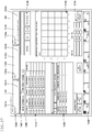
- the packaging progress display area 1100 displays the progress and state of packaging.
- the packaging list display area 1110 is an area for displaying a list of prescription information.
- the packaging device operating area 1140 is an area for operating the packaging device.
- the distribution position/amount guide display area 1150 for a manual distribution drug is to be used at the time of manual distribution prescription and is an area for displaying positions to which the manual distribution drug is distributed and the amount of the drug.
- the function key display area 1130 is an area for performing various kinds of processing.
- the packaging progress display area 1100 updates the progress.
- the prescription ID display region 1101a of the L-Drower region 1101 displays a prescription ID number.
- the display is cleared.
- a list of prescriptions including a packaging prescription which involves use of only the tablet cassette 16 in which tablets to be packaged are received from prescription information based on a prescription ID and a prescription which involves both of a prescription using the tablet cassette 16 and a prescription of manual distribution is displayed in the packaging list display area 1110.
- the With Cassette tab 1160 and the Without Cassette tab 1161 When any one of the With Cassette tab 1160 and the Without Cassette tab 1161 is selected, information based on a prescription ID listed at the top in the packaging list display area 1110, that is, a prescription ID relating to a prescription currently being subjected to the packaging operation is displayed. Accordingly, when a manual distribution operation is required, information required for the manual distribution is displayed for an operator in the distribution position/amount guide display area 1150 for a manual distribution drug, thereby enabling the operator to easily perform the manual distribution operation. In particular, in the case of "Without Cassette", an operator performs the manual distribution operation for tablets with respect to the tray 26.
- the medicine list display area 1120 displays information relating to the manual distribution operation.
- a drug dispensed from the tablet cassette 16 and a total number of a drug having been manually distributed are displayed.
- the all medicine display button is clicked, in the distribution position/amount guide display area 1150 for a manual distribution drug, both of a prescribed medicine corresponding to the manual distribution drug and tablets dispensed from the tablet cassette 16 in the prescription are displayed.
- information relating to the total amount of all of drug tablets to be received is displayed.
- a manual distribution skip button is displayed, and when the manual distribution skip button is clicked, confirmation of completion of the manual distribution tablets is skipped.
- control device 200 of this embodiment is capable of controlling the monitor 101 of the input device 100 to display the progress of the tablet packaging device 11, thereby being capable of successively notifying an operator of progress information of packaging.
Landscapes
- Engineering & Computer Science (AREA)
- Mechanical Engineering (AREA)
- Health & Medical Sciences (AREA)
- Public Health (AREA)
- Animal Behavior & Ethology (AREA)
- General Health & Medical Sciences (AREA)
- Life Sciences & Earth Sciences (AREA)
- Veterinary Medicine (AREA)
- Physics & Mathematics (AREA)
- General Physics & Mathematics (AREA)
- Medical Informatics (AREA)
- Basic Packing Technique (AREA)
- Medical Preparation Storing Or Oral Administration Devices (AREA)
Abstract
Description
- This invention relates to a tablet packaging device, which is configured to package prescribed tablets for every administration into a tray of a blister pack type (hereinafter referred to simply as "tray").
- There has hitherto been known a tablet packaging device configured to automatically distribute and pack prescribed tablets into individual accommodation recess portions of a tray that is called "weekly calendar pack" including accommodation recess portions arranged in seven rows by four columns (Patent Literature 1). The tray is capable of accommodating tablets packaged for four times of administrations per day into accommodation recess portions corresponding to one row, and by seven columns in total, thereby being capable of accommodating tablets for administrations per week.
- The tablet packaging device of
Patent Literature 1 is a tablet packaging device configured to receive all of the tablets corresponding to one tray through use of one carrier, move the carrier to a position above a tray waiting at a discharging position, and open a shutter forming a bottom wall of the carrier, thereby simultaneously discharging the tablets into all of the accommodation recess portions of the tray. This device has an advantage in that high packaging efficiency is achieved with less erroneous packaging, and the structure can be simplified. - [PTL 1]
JP 5870931 B2 - The tablet packaging device described in
Patent Literature 1 has the following configuration. The carrier having received tablets corresponding to one tray is moved to the position of the tray mounted to a drawer mounted in such a manner as to be freely placed in and out. Then, the shutter of the carrier is opened to discharge the tablets. Thus, the tray is in a state of being placed on the drawer until tablets are discharged to one tray, and the next tray for another prescription cannot be set until the operation of discharging the tablets to the one tray is terminated. Therefore, there is a problem in that the operation efficiency is not improved. - Moreover, at the time of discharging tablets from the carrier to the tray, there is also a risk of causing erroneous packaging in which the fallen tablets bounce in the recess portion of the tray and jump out to an outside of the recess portion.
- In view of the above-mentioned problems, this invention has an object to provide a tablet packaging device, which is capable of shortening operation time required for packaging tablets for one tray and is capable of more reliably packaging tablets.
- In order to solve the above-mentioned problems, according to one embodiment of the present invention, there is provided a tablet packaging device, including: a tablet accommodating portion configured to store a plurality of kinds of drugs and dispense a drug based on prescription information; and a packaging portion configured to dispense the tablets, which are dispensed from the tablet accommodating portion, through a dispensing port and distribute and accommodate the tablets to a tray having a plurality of accommodation recess portions, wherein the packaging portion includes: a tray loading unit to which the tray is mountable; a tray unloading unit, which is arranged adjacent to the tray loading unit, and to which the tray accommodating the tablets is mountable; a tray driving unit, which is configured to move the supported tray between positions of the tray loading unit and the tray unloading unit, and move the desired accommodation recess portion of the tray to the dispensing port for tablets; a tray attaching unit configured to attach the tray from the tray loading unit to the tray driving unit; and a tray detaching unit configured to detach the tray accommodating the tablets from the tray driving unit and place the tray on the tray unloading unit (Claim 1).
- The tray driving unit is configured to support the tray at positions above the tray loading unit and the tray unloading unit, wherein the tray driving unit is configured to move the tray in a horizontal plane, wherein the tray attaching unit is configured to lift up the tray from the tray loading unit and attach the tray to the tray driving unit, wherein the tray detaching unit is configured to detach the tray accommodating the tablets from the tray driving unit, lower the tray, and place the tray on the tray unloading unit (Claim 2).
- The tray driving unit includes an XY robot configured to move the supported tray in a width direction and a front-and-rear direction of the device in a horizontal plane (Claim 3).
- The tray driving unit includes: a conveyance stage, which is capable of being positioned above the tray loading unit and the tray unloading unit, and includes division chambers, which are arranged at positions matching the accommodation recess portions of the tray and are opened in the up-and-down direction; and a tray fixing member configured to attach the tray to a lower side of the conveyance stage under a state in which positions of the division chambers and positions of the accommodation recess portions of the tray match each other (Claim 4).
- The tray is mounted to the tray loading unit under a state in which the tray is placed on an adapter, which is opened on an upper side and is capable of accommodating the tray from the upper side, wherein the adapter includes stage engagement ratchets which are attachable to and detachable from tray fixing members of the conveyance stage, wherein the tray fixing members extend downward from side edges of the conveyance stage and have engagement holes which are engageable with the stage engagement ratchets, wherein the tray is attached to the tray driving unit in a state of being sandwiched between a lower surface of the conveyance stage and an upper surface of the adapter, and the conveyance stage is driven so that one of the division chambers is located at a position corresponding to the dispensing port to receive the tablets dispensed from the dispensing port, and wherein the tray having the tablets discharged thereto and accommodated therein is mounted to the tray unloading unit in a state of being placed on the adapter (Claim 5) .
- The tray loading unit is formed of a drawer provided so as to be freely placed in and out with respect to the packaging portion and includes a first placement table configured to place the tray inside the drawer, wherein the first placement table is located at a tray handling position outside the packaging portion when the drawer is drawn out, and the first placement table is located at a waiting position inside the packaging portion when the drawer is pushed in, and wherein the tray attaching unit includes a first raising/lowering device, which is provided below the waiting position of the tray loading unit and is configured to attach the tray to a lower surface of the conveyance stage located above the waiting position by lifting up the tray located at the waiting position from the lower side (Claim 6).
- The first placement table of the tray loading unit includes a set of first support members configured to support both ends of the adapter in a width direction, and a region between the first support members is a first raising/lowering device passage region for allowing the first raising/lowering device to pass therethrough (Claim 7).
- The tray unloading unit is formed of a drawer provided so as to be freely placed in and out and includes a second placement table configured to place the tray inside the drawer, wherein the second placement table is set so as to be located at a tray handling position outside the packaging portion when the drawer is drawn out, and the second placement table is set so as to be located at a waiting position inside the packaging portion when the drawer is pushed in, and wherein the tray detaching unit includes a second raising/lowering device, which is provided below the waiting position of the tray unloading unit with respect to the packaging portion and is configured to support, from below, the tray detached from the lower surface of the conveyance stage located above the waiting position and mount the tray to the placement table of the tray unloading unit (Claim 8).
- The second placement table of the tray unloading unit includes a set of second support members configured to support both ends of the adapter in a width direction, and a region between the second support members is a second raising/lowering device passage region for allowing the first raising/lowering device to pass therethrough (Claim 9).
- The second raising/lowering device includes a releasing member configured to disengage the tray fixing members at the time of supporting, from below, the tray attached to the lower surface of the conveyance stage (Claim 10).
- The tablet packaging device further includes a manual-distribution unit configured to add tablets to the accommodation recess portions of the tray, wherein the manual-distribution unit includes: a manual-distribution container including: a manual-distribution member having division chambers, which are opened on upper and lower sides and are arranged at positions matching with the accommodation recess portions of the tray; and a shutter, which is slidably provided to a bottom surface of the manual-distribution member and is configured to open and close the division chambers; and a drawer portion, which is provided so as to allow the manual-distribution container to be pushed in and drawn out, and is set so as to allow the manual-distribution container to be located at a tablet distribution position outside the packaging portion when the drawer portion is drawn out and allow the manual-distribution container to be located at a discharging position at which the accommodation recess portions of the tray having the tablets discharged thereto and accommodated therein and the division chambers correspond to each other (Claim 11).
- The drawer portion of the manual-distribution unit is provided at a position above the tray unloading unit, and the discharging position of the drawer portion of the manual-distribution unit matches the waiting position of the tray unloading unit as seen from above (Claim 12).
- The manual-distribution container is located above the conveyance stage, the shutter includes engagement pieces extending downward to an end portion of the conveyance stage on a downstream side in the moving direction of the conveyance stage, and is attached while being urged under a state in which the division chambers of the manual-distribution container are closed, and the engagement pieces engage with the conveyance stage along with movement of the conveyance stage to slide the shutter toward the downstream side in the moving direction of the conveyance stage, thereby opening the division chambers (Claim 13).
- The tablet accommodating portion includes: a tablet cassette shelf configured to hold a plurality of tablet cassettes; and a tablet conveying device configured to convey tablets, which are supplied from a corresponding tablet cassette shelf in accordance with a prescription, to a predetermined position, wherein the tablet conveying device includes: a primary conveyance portion configured to convey tablets in a direction intersecting a direction from the tablet cassette shelf side toward the packaging portion side; and a secondary conveyance portion configured to convey the tablets in the direction from the tablet cassette shelf side toward the packaging portion, and wherein the tablet conveying device is configured to perform: a first operation of conveying the tablets with the primary conveyance portion and thereafter conveying the tablets with the secondary conveyance portion; and a second operation of receiving the tablets from the tablet cassette shelf without passage through the primary conveyance portion and conveying the tablets with the secondary conveyance portion (Claim 14).
- The primary conveyance portion includes: a catching portion configured to catch supplied tablets; and a tablet push-out piece portion, which is movable in a conveyance direction of tablets in the primary conveyance portion, and is configured to push and move the tablets located at the catching portion (Claim 15).
- The tablet conveying device further includes a leading portion configured to temporarily accommodate tablets supplied and led from the tablet cassette (Claim 16).
- The leading portion includes: an accommodation space including a discharging port portion configured to primarily accommodate the tablets having been led thereinto and discharge the tablets to the primary conveyance portion side or the secondary conveyance portion; and a movable catching member which is switchable between a tablet catching posture of closing the discharging port portion and a tablet catching posture of allowing the discharging port portion to communicate with an outside (Claim 17).
- In the tablet catching posture, the movable catching member is inclined with respect to a horizontal direction to catch tablets having been led and accommodate the tablets in the leading portion (Claim 18).
- In the tablet packaging device according to this invention, the tray mounted to the tray loading unit is attached to the tray driving unit, and the tray is then driven, thereby being capable of directly packaging tablets into the tray. Thus, the tray is not placed on the tray loading unit during the packaging operation. Moreover, the tray having tablets discharged thereto and accommodated therein is mounted to the tray unloading unit. Thus, after the tray is delivered from the tray loading unit to the tray driving unit, a state in which the tray is not mounted to the tray loading unit is brought about. Accordingly, during the operation with the tray, a tray for the next prescription can be mounted to the tray loading unit. Therefore, the operation efficiency of the packaging operation for the tray can be improved.
- Moreover, in the packaging operation for the tray, tablets are directly packaged into the tray. Thus, the number of times of moving tablets during the packaging operation for the tray is reduced as compared to a case in which tablets are moved to the tray after packaging the tablets into the carrier. Therefore, the risk of causing erroneous packaging can be reduced.
-
-
FIG. 1 is a front view of a tablet packaging device according to an embodiment of the present invention. -
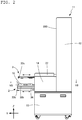
FIG. 2 is a side view of the tablet packaging device ofFIG. 1 . -
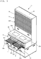
FIG. 3 is a perspective view for illustrating a state in which drawers of the tablet packaging device ofFIG. 1 are opened. -
FIG. 4 is a perspective view for illustrating a state in which a drawer of a manual-distribution unit of the tablet packaging device ofFIG. 1 is opened. -
FIG. 5A is a partially cutaway plan view for illustrating a state in which a lid is affixed to a tray. -
FIG. 5B is a sectional view taken along the line Vb-Vb ofFIG. 5A . -
FIG. 6A is a partial enlarged sectional view ofFIG. 5B . -
FIG. 6B is a partial enlarged sectional view for illustrating a state during use ofFIG. 5B . -
FIG. 6C is a partial enlarged sectional view for illustrating a state during use ofFIG. 5B . -
FIG. 7 is a sectional view taken along the line VII-VII in a state in which a lid ofFIG. 2 is removed. -
FIG. 8A is an explanatory view for illustrating a positional relationship between a first placement table in a waiting position and a first raising/lowering device, as seen from a side of a loading drawer. -
FIG. 8B is a side view for illustrating a state in which the first raising/lowering device is raised. -
FIG. 9 is a perspective view for illustrating a configuration of a conveyance stage and the coupling structure with an adapter. -
FIG. 10 is a perspective view for illustrating configurations of the adapter and the tray. -
FIG. 11A is a schematic view for illustrating movement positions of the conveyance stage. -
FIG. 11B is a plan view for schematically illustrating a configuration of the conveyance stage. -
FIG. 12 is a sectional view taken along the line XII-XII ofFIG. 10 . -
FIG. 13 is a sectional view taken along the line XIII-XIII ofFIG. 12 . -
FIG. 14 is a partially omitted enlarged sectional view taken along the line XIV-XIV ofFIG. 7 . -
FIG. 15 is an exploded perspective view for illustrating a configuration of a manual-distribution container and a positional relationship with the conveyance stage. -
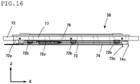
FIG. 16 is a side view for illustrating a configuration of the manual-distribution container ofFIG. 15 . -
FIG. 17A is an explanatory process view for illustrating an operation procedure of the conveyance stage for opening the shutter of the manual-distribution container, and is an illustration of a fully closed state in which bottom surfaces of division chambers are closed. -
FIG. 17B is an explanatory process view for illustrating the operation procedure of the conveyance stage for opening the shutter of the manual-distribution container, and is an illustration of a state in which the division chambers are opened. -
FIG. 17C is an explanatory process view for illustrating the operation procedure of the conveyance stage for opening the shutter of the manual-distribution container, and is an illustration of a state in which the division chambers are each half-opened. -
FIG. 17D is an explanatory process view for illustrating the operation procedure of the conveyance stage for opening the shutter of the manual-distribution container, and is an illustration of a fully closed state of the division chambers. -
FIG. 18 is a plan view of the manual-distribution container in the state ofFIG. 17A . -
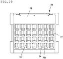
FIG. 19 is a plan view of the manual-distribution container in the state ofFIG. 17C . -
FIG. 20 is a plan view of the manual-distribution container in the state ofFIG. 17D . -
FIG. 21 is an explanatory view for illustrating a process of removing the adapter from the conveyance stage. -
FIG. 22 is an explanatory view for illustrating the process of removing the adapter from the conveyance stage, and is an illustration subsequent to theFIG. 21 . -
FIG. 23 is an explanatory view for illustrating the process of removing the adapter from the conveyance stage, and is an illustration subsequent toFIG. 22 . -
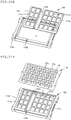
FIG. 24A is an exploded perspective view for illustrating a modification example of the adapter. -
FIG. 24B is an illustration of a modification example of the tray, and is an exploded perspective view for illustrating a state in which the tray is received in the adapter. -
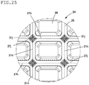
FIG. 25 is a partial enlarged plan view for illustrating a state in which a lid cover is affixed to the tray ofFIG. 24 . -
FIG. 25 is a perspective view for schematically illustrating a configuration a tray of another modification example. -
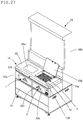
FIG. 27 is a view for illustrating an exterior configuration of a tablet packaging device of a modification example including a manual-distribution unit of another embodiment. -
FIG. 28 is a partial enlarged perspective view for illustrating a configuration of the manual-distribution unit in a state in which a lid cover of the tablet packaging device ofFIG. 27 is opened so that the manual-distribution unit is exposed to an outside. -
FIG. 29 is a perspective view for illustrating an arrangement configuration of a tablet accommodating portion of the tablet packaging device ofFIG. 1 . -
FIG. 30 is a perspective view for illustrating a configuration of a tablet supplying device included in the tablet accommodating portion ofFIG. 29 . -
FIG. 31 is a perspective view for illustrating a configuration of a lateral conveyance portion included in the tablet accommodating portion ofFIG. 29 . -
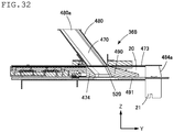
FIG. 32 is a sectional view for illustrating a configuration of a tablet push-out portion of the tablet supplying device ofFIG. 30 . -
FIG. 33 is a block diagram for illustrating a control configuration for the tablet packaging device according to the embodiment of the present invention. -
FIG. 34 is an explanatory view for illustrating a state in which accommodation recess portions are regularly arranged on the tray. -
FIG. 35 is an explanatory view for illustrating a state in which the accommodation recess portions are randomly arranged on the tray. -
FIG. 36 is an explanatory view for illustrating a state in which the accommodation recess portions are randomly arranged on the tray. -
FIG. 37 is an explanatory view for illustrating the progress of the tablet packaging device displayed on a monitor. - Now, with reference to the accompanying drawings, a tablet packaging device according to an embodiment of this invention is described.
-
FIG. 1 to FIG. 4 are illustrations of an exterior configuration of atablet packaging device 11 according to this embodiment. Thetablet packaging device 11 illustrated inFIG. 1 includes, for example, atablet accommodating portion 13, apackaging portion 14, and anaccommodating portion 15. Thetablet accommodating portion 13 is provided at an upper half part of aframe 12. The packaging portion 14 (seeFIG. 2 ) projecting forward from the upper half part is provided at a lower half part of aframe 12. Theaccommodating portion 15 for empty trays or the like is provided on a lower side of thepackaging portion 14. A large number oftablet cassettes 16 are accommodated in multiple stages in thetablet accommodating portion 13, andtablet feeders 17 are installed on a lower side of thetablet cassettes 16. - An
input device 100 is connected to thetablet packaging device 11. Theinput device 100 includes a code reader (not shown) configured to read a barcode or a QR code (trademark) given to a prescription. Theinput device 100 is configured to give prescription information, which is based on data read through use of the code reader, to thetablet packaging device 11. Theinput device 100 includes operation input devices such as a keyboard (not shown) in addition to the code reader, and information such as prescription information can be given to thetablet packaging device 11 through use of the operation input devices. - The
tablet packaging device 11 produces a prescription ID corresponding to the received prescription information. The prescription ID and the prescription information are associated with each other. The prescription information includes, for example, information required for packaging such as a kind of a drug, the number of tablets, and administration timings, and patient information. The prescription ID is used at the time of reading prescription information associated therewith. - The
input device 100 is formedof, for example, apersonal computer. The personal computer includes, for example, a CPU, a ROM, and a RAM. The CPU is configured to perform arithmetic processing based on various programs stored in the ROM. - The
input device 100 formed of a personal computer sends the prescription information to thetablet packaging device 11. Moreover, based on processing state information that is given by thetablet packaging device 11, for example, progress information of thetablet packaging device 11 is displayed on amonitor 101. - When the
input device 100 is connected to a system of a pharmacy, a hospital, or the like through a communication network such as a LAN or the Internet, theinput device 100 is capable of obtaining prescription data from the system of a pharmacy, ahospital, or the like via the communication network. Then, theinput device 100 gives the prescription data obtained from the system of a pharmacy, a hospital, or the like to thedrug packaging device 11. - Regarding the tablet packaging device according to this embodiment, directions are defined as indicated in
FIG. 1 andFIG. 2 . That is, a width direction of the device corresponds to an X axis. A front-and-rear direction of the device corresponds to a Y axis. A height direction of the device corresponds to a Z axis. In the following, the directions of the device are described based on the definitions described above. - The
tablet accommodating portion 13 includes the large number oftablet cassettes 16 and thetablet feeders 17 provided to thetablet cassettes 16. The large number oftablet cassettes 16 are configured to store a plurality of kinds of tablets as drugs. In accordance with prescription information corresponding to a prescription ID, tablets are dispensed from thetablet cassette 16 by thetablet feeder 17, and the tablets fall into atablet supplying device 19. The number of the tablets is counted when the tablets pass through a passage of thetablet feeder 17, and a predetermined number of tablets fall into thetablet supplying device 19. - On a back side of the
tablet accommodating portion 13, back lids of an opening/closing type (not shown) are installed. The back lids include an upper lid configured to open upward and a lower lid configured to open downward. When the lower lid is opened, falling passages for tablets into thetablet supplying device 19 described later are opened. Accordingly, only the falling passages for tablets can be cleaned. - The
tablet supplying device 19 is provided below thetablet feeders 17. Thetablet supplying device 19 is configured to receive tablets which fall from thetablet feeder 17. The tablets to be received by thetablet supplying device 19 are tablets selected from tablets stored in thetablet cassettes 16, and the number and a kind of the tablets are determined based on prescription information. Thetablet supplying device 19 collects the received tablets to a center and delivers the collected tablets to a tablet push-out passage 20 (seeFIG. 7 ) extending in the front-and-rear direction. The tablets are delivered toward a near side in the tablet push-out passage 20 and dispensed through a dispensingport 21, which is located at an upper part of thepackaging portion 14 and directed downward. Prescribed tablets for every administration, for example, tablets of the amount corresponding to four times of administrations per day by one week or three times of administrations per day by five days are intermittently dispensed through the dispensingport 21 in each cycle of a conveying process described later. - The tablet cassettes 16 and the
tablet feeders 17 are accommodated in atablet cassette shelf 350 as illustrated inFIGS. 1 to 4 andFIG. 29 . Thetablet cassette shelf 350 is opened and closed in an up-and-down direction by alouver shutter 18. - As illustrated in
FIG. 29 , thetablet cassette shelf 350 has the structure including acontainer attaching portion 361 and thetablet supplying device 19. Thecontainer attaching portion 361 is configured to hold the plurality oftablet cassettes 16 andtablet feeders 17. Thetablet supplying device 19 is located below thecontainer attaching portion 361. Tablets having fallen from thetablet feeder 17 are collected into thetablet supplying device 19. Moreover, thetablet cassette shelf 350 of this embodiment is capable of holding different types (two types) oftablet cassettes 16. - A part of the
tablet supplying device 19 communicates with the tablet push-out passage 20 which is formed in such a manner as to extend up to thepackaging portion 14. Further, a front end side of the tablet push-out passage 20 of thetablet supplying device 19 is coupled to the dispensingport 21, thereby forming a series of flow passages. - Tablets stored in the
tablet cassette 16 received in thetablet cassette shelf 350 are dispensed to thetablet feeder 17. The tablets dispensed from thetablet feeder 17 fall downward to be led into thetablet supplying device 19 located below thetablet feeder 17. Then, after being carried to the tablet push-out passage 20 inside thetablet supplying device 19, the tablets are pushed out from the tablet push-out passage 20 to the dispensingport 21 and then are packaged and accommodated in atray 24 at thepackaging portion 14. Now, thetablet supplying device 19 is described in detail. - As illustrated in
FIG. 30 , thetablet supplying device 19 mainly includes tablet catching portions 365 (365a, 365b, 365c, and 365d) (leading portion), two right and left lateral conveyance portions 366 (primary conveyance portion), and a falling passage forming portion 367 (passage forming portion) . Thetablet catching portions 365 are located on an upper side. Thelateral conveyance portions 366 and the fallingpassage forming portion 367 are located below thetablet catching portions 365. A tablet push-out portion 368 (secondary conveyance portion) is formed below the fallingpassage forming portion 367. Thus, thetablet supplying device 19 has a three-stage stacking structure in which the tablet catching portions 365 (leading portion) having a laterally extending shape, the lateral conveyance portions 366 (primary conveyance portion) having a laterally extending shape similar to that of thetablet catching portions 365, and the tablet push-out portion 368 (secondary conveyance portion) having a vertically extending shape are vertically stacked. - The tablet catchingportions 365 (365a, 365b, 365c, 365d, and 365e) located in an uppermost stage are portions configured to catch tablets which fall from above, and function as a leading portion for tablets in the
tablet supplying device 19 as a whole. Thetablet catching portions 365 has the structure including end-sidetablet catching portions tablet catching portions tablet catching portion 365e. The end-sidetablet catching portions tablet catching portions tablet catching portions tablet catching portion 365e is provided between the intermediatetablet catching portions tablet catching portions tablet catching portions tablet catching portion 365e are arranged in such a manner as to be continuous with each other in the X direction. - As illustrated in
FIG. 30 , the end-sidetablet catching portions tablet catching portions tablet catching portion 365e each have a substantially rectangular parallelepiped shape extending in a right-and-left direction and have atablet leading space 370 formed therein. Thetablet leading space 370 functions as an accommodation space for tablets. As illustrated inFIG. 30 , the intermediatetablet catching portions tablet leading space 370 that is the largest in size in the right-and-left direction. The size of thetablet leading space 370 of each of the end-sidetablet catching portions tablet leading space 370 of each of the intermediatetablet catching portions 36b and 365c, and the size of the leadingspace 370 of the centertablet catching portion 365e is the smallest. - The
tablet leading space 370 of each of the tablet catching portions 365 (365a, 365b, 365c, 365d, and 365e) is a space which is communicable with an outside in the up-and-down direction, and has an opening surface serving as a leading port for tablets on an upper side thereof. - The end-side
tablet catching portions FIG. 29 ) via thetablet feeder 17. Then, the end-sidetablet catching portions tablet leading space 370, thereby supplying the tablets to a lower side (lateral conveyance portion 366 and fallingpassage forming portion 367, seeFIG. 30 ) . In other words, after temporarily storing the tablets inside the respectivetablet leading spaces 370, the end-sidetablet catching portions - The intermediate
tablet catching portions tablet catching portion 365e each have the same basic structure as the end-sidetablet catching portions - Tablets led into the
tablet leading space 370 of each of the end-sidetablet catching portions tablet catching portions tablet catching portions 365 are supplied to one of thelateral conveyance portions 366 located in an intermediate stage. Then, the tablets are pushed to move in a lateral direction and supplied to the fallingpassage forming portion 367. Finally, the tablets are led into the tablet push-out portion 368 (secondary conveyance portion) located in a lowermost stage. - Tablets led into the
tablet leading space 370 of the centertablet catching portion 365e directly fall into the fallingpassage forming portion 367 without passing through thelateral conveyance portions 366 located in the intermediate stage and are led into the tablet push-out portion 368 (secondary conveyance portion) located in the lowermost stage. - Now, the
lateral conveyance portion 366 located in the intermediate stage is described. As illustrated inFIG. 30 , twolateral conveyance portions 366, which are symmetrical to each other in the X direction and have the same structure, are arranged in the intermediate stage in such a manner as to be lined up in the X direction. - As illustrated in
FIG. 31 , thelateral conveyance portion 366 includes a tablet catching groove portion 410 (catching portion), awheel traveling portion 411, and aguide arranging portion 412. Specifically, thewheel traveling portion 411, the tablet catchinggroove portion 410, and theguide arranging portion 412 are arranged in the stated order from the near side in the Y direction inFIG. 31 and are formed integrally with one another. Further, amotor 445 is arranged below these components. - The tablet catching
groove portion 410 is a portion into which the tablets which fall from the end-sidetablet catching portions tablet catching portions tablet catching portions 365 described above are led. The tablet catchinggroove portion 410 is a groove-like portion recessing downward and has a substantially rectangular sectional shape defining a space extending in the right-and-left direction. - At an end portion of the tablet catching
groove portion 410 located on one end side in a longitudinal direction (end portion in the X direction ofFIG. 31 ), there is formed a tablet dischargingport portion 418, which is an opening portion allowing an inside and an outside to communicate with each other. The end portion at which the tablet dischargingport portion 418 is formed is an end portion located on the center side of thetablet supplying device 19 in the X direction (see, for example,FIG. 30 ). This end portion is continuous with the fallingpassage forming portion 367. - The two
lateral conveyance portions 366 are symmetrical to each other in the X direction, and the tabletdischarge port portions 418 of the twolateral conveyance portions 366 are arranged adjacent to each other. The two tablet dischargingport portions 418 are arranged across the fallingpassage forming portion 367. - In the tablet catching
groove portion 410, as illustrated inFIG. 31 , a tablet push-out piece portion 438 is arranged. The tablet push-out piece portion 438 is arranged inside the tablet catchinggroove portion 410 and is configured to move in the X direction along the tablet catchinggroove portion 410. InFIG. 31 , illustration is given of a state in which the tablet push-out piece portion 438 has moved to the vicinity of the tablet dischargingport portion 418. At the time of catching the falling tablets, the tablet push-out piece portion 438 is located at a waiting position that is most apart from the center side in the X direction. Then, the tablet push-out piece portion 438 pushes out the tablets having been led into the tablet catchinggroove portion 410 toward the fallingpassage forming portion 367. - With such a configuration, tablets can be pushed out in the X direction by moving the tablet push-
out piece portion 438 inside the tablet catchinggroove portion 410. - That is, the tablet push-
out piece portion 438 is allowed to wait on one end side of the tablet catchinggroove portion 410 in the longitudinal direction, which is also the end portion side located at the position apart from the tablet dischargingport portion 418. Then, tablets are caused to fall from thetablet catching portions 365 described above so that the tablets are supplied to the inner space of the tablet catchinggroove portion 410. After that, the tablet push-out piece portion 438 moves in the X direction along the tablet catchinggroove portion 410 to the vicinity of the tablet dischargingport portion 418, thereby pushing out the tablets to the outside from the tablet dischargingport portion 418. - As illustrated in
FIG. 32 , the tablet push-outportion 368 located in the lowermost stage includes ashooter 480 and a push-outpassage forming portion 473. In the push-outpassage forming portion 473, there is provided atablet conveying device 474 configured to convey supplied tablets in the Y direction. - As illustrated in
FIG. 30 andFIG. 32 , theshooter 480 is attached on an upper side of the push-outpassage forming portion 473 and has a first tablet-supplyinghole 470 passing through the inside of theshooter 480 in the up-and-down direction. An opening portion located on an upper side of the first tablet-supplyinghole 470 serves as a leading port (tablet leading port 480a) for leading tablets at the time of supplying the tablets to the tablet push-outportion 368. - The push-out
passage forming portion 473 has thetablet conveying device 474 incorporated therein. As illustrated inFIG. 32 , thetablet conveying device 474 has the structure including anupper pad portion 490 and aconveyor portion 491 and is caused to linearly move in the tablet push-out passage 20 by a driving device (not shown). - As illustrated in
FIG. 32 , thetablet conveying device 474 has, at a part thereof, anaccommodation hole 520 passing from a top surface to a bottom surface and is configured to convey tablets . - In the
tablet packaging device 11, tablets having been dispensed through the dispensingport 21 via thetablet supplying device 19 are finally accommodated in thetray 24 illustrated inFIGS. 5 andFIGS. 6 . Next, thetray 24 is described. - In
FIG. 5A and FIG. 5B , illustration is given of a state in which alid sheet 25 is affixed to an open surface of thetray 24. Thetray 24 includesaccommodation recess portions 26, which are divided in a grid pattern of seven rows by four columns . Opposingside walls 27a located on long sides of thetray 24, opposingside walls 27b located on short sides of thetray 24, anddivision walls 27c dividing an area defined by theside walls accommodation recess portions 26. - The
accommodation recess portions 26 of thetray 24 are arranged in the grid pattern of seven rows by four columns as illustrated inFIGS. 5 . Besides, for example, theaccommodation recess portions 26 may be arranged in a pattern of seven rows by five columns. Details regarding how to handle thetray 24 having a different size in thetablet packaging device 11 are described later. - Thickness portions of the
side walls division walls 27c on the bottom surface side havegrooves 27d so as to have the thickness that maintains a certain strength. The bottom surface of theaccommodation recess portion 26 has a thickness thinner than that of the thickness portions and is formed so as to have a large number of irregularly-shapedwrinkles 28. The bottom surface is thin and has a large number ofwrinkles 28, thereby being capable of exerting a buffering function fortablets 29 accommodated therein. Moreover, when the bottom surface is pushed upward, the bottom surface is deformed into a mountain shape (see the two-dot chain line ofFIG. 6C ), thereby allowing thetablets 29 provided therein to be easily taken out. - The
lid sheet 25 described above is a sheet made of paper or the like having a size matching with that of an entire surface of thetray 24 on the open side, and is affixed at the portions of theside walls 27a on the long sides, theside walls 27b on the short sides, and thedivision walls 27c described above with use of an adhesive 31 (seeFIG. 6A ). Thelid sheet 25 has break/removal portions 31b each surrounded by abreak line 31a. Thebreak line 31a is a half-cut line or a perforated line forming a rectangle that has a size matching with that of the accommodation recess portion 26 (seeFIG. 6A ) . Theaccommodation recess portion 26 may have a pinch part for convenience in opening the break/removal portion 31b. - Moreover, the
lid sheet 25 has projecting-portion insertion holes 31c, which are formed at positions corresponding to projectingportions 27e formed on theside walls tray 24. The projecting-portion insertion hole 31c may be formed into a through hole or may be formed into a cutout connecting to a peripheral edge of thelid sheet 25. The projectingportion 27e and the projecting-portion insertion hole 31c are fitted to each other, thereby being capable of preventing misalignment of the lid sheet and erroneous combination with types of thetray 24. When the adhesive 31 is provided to a part around the projecting-portion insertion hole 31c, it is difficult to set the projectingportion 27e and thelid sheet 25. Therefore, portions indicated bybroken lines 31g are subjected to adhesive elimination of not providing the adhesive 31. - Further, at the
side walls tray 24 and at an upper edge of thelid sheet 25, there are formedhook insertion holes hook insertion hole 31d, it is difficult to set the projectingportion 27e oftray 24 and thelid sheet 25. Therefore, a portion indicated by thebroken line 31g is subjected to adhesive elimination of not providing the adhesive 31. - As a modification example, the
tray 24 and thelid sheet 25 may havedivision lines FIG. 25 ), which are perforation lines or the like surrounding theaccommodation recess portions 26, so that thetray 24 and thelid sheet 25 can each be cut in such a manner as to correspond to theaccommodation recess portions 26. In this configuration, as illustrated inFIG. 25 , processedregions 31j located atperipheral edge portions 27j of thedivision lines 27h of thetray 24 are not subjected to application of the adhesive 31 for affixing thetray 24 and thelid sheet 25 to each other or are subjected to adhesive elimination, thereby allowing thelid sheet 25 to be easily peeled off from the divided tray. - In margin portions of the break/
removal portions 31b corresponding to the seven rows in the up-and-down direction, there are provided seven-days indications 32 anddate indications 33 corresponding to the seven-days indications 32. Moreover, in margin portions corresponding to the four columns in the right-and-left direction, there are providedadministration timing indications 34 such as "MORNING" to "BEFORE SLEEPING" and other indications. Moreover, on each of the break/removal portions 31b, there are providedprescription indications 35 such as a name of a prescribee, an administration timing, a name of tablets, the amount of the tablets, and the like. In the case of the illustration ofFIG. 5A , there are provided indications of receiving tablets of an amount corresponding to four times a day for one week. However, in some cases, depending on a prescription, a different amount of tablets are accommodated, such as tablets of an amount corresponding to three times a day for five days. - Moreover,
barcodes 31e are provided to thetray 24 and thelid sheet 25. These barcodes contain information relating to serial numbers and the like of thetray 24 and thelid sheet 25 and are used when thetablet packaging device 11 checks a tray size, positions and the number of theaccommodation recess portions 26, and the like. Moreover, thebarcodes 31e may contain a prescription ID. The prescription ID is associated with the prescription information (including patient information) held by thetablet packaging device 11 and is used for preventing an error at the time of affixing thelid sheet 25 to thetray 24 based on the prescription information. - A prescribee presses a corresponding break/
removal portion 31b with a fingertip to break the break/removal portion 31b along thebreak line 31a at each of four administration timings in a corresponding day (seeFIG. 6B ). The break/removal portion 31b is pressed into theaccommodation recess portion 26. Thus, the break/removal portion 31b is taken out by pinching with fingertips, or is taken out together with thetablets 29 by pushing up a bottom surface of theaccommodation recess portion 26 with a fingertip (seeFIG. 6C ). - Along with the action of taking out the
tablets 29, the break/removal portion 31b is broken and removed, and theaccommodation recess portion 26 is opened. Therefore, it can be easily checked whether or not administration has been forgotten by only distinguishing whether or not theaccommodation recess portion 26 is opened. - Next, the
packaging portion 14 is described in detail. As illustrated inFIG. 3 andFIG. 4 , thepackaging portion 14 is covered with acover lid 22 in a normal state, and an inside of thepackaging portion 14 can be observed throughinspection windows tray loading unit 1 received inside can be observed through theinspection window 22a, and atray unloading unit 2 received inside can be observed through theinspection window 22b. When thecover lid 22 is removed, thepackaging portion 14 is exposed to the outside .FIG. 7 is a transverse sectional view for illustrating a state in which thecover lid 22 is removed and an upper half part of theframe 12 is cut and removed. - As illustrated in
FIG. 1 ,FIG. 3 , andFIG. 4 , in thepackaging portion 14, there are provided thetray loading unit 1, thetray unloading unit 2, and a manual-distribution unit 3 as units which can be visually checked from the outside of the device. - As illustrated in
FIG. 3 , on the front side of thepackaging portion 14, as component members of thetray loading unit 1 and thetray unloading unit 2, there are provided aloading drawer 23a and anunloading drawer 23b, which are each capable of being drawn forward to the outside of thepackaging portion 14 and pushed into thepackaging portion 14. In the case of the illustration ofFIG. 3 , theloading drawer 23a and theunloading drawer 23b are manually drawn out and pushed in (see double-head arrows ofFIG. 2 andFIG. 7 ). However, theloading drawer 23a and theunloading drawer 23b may be automatically driven. - Moreover, as illustrated in
FIG. 4 , the manual-distribution unit 3 similarly includes amanual distribution drawer 23c, which is capable of being drawn forward to the outside of thepackaging portion 14 and pushed into thepackaging portion 14. A specific configuration of the manual-distribution unit 3 is described later. - Besides the
tray loading unit 1, thetray unloading unit 2, and the manual-distribution unit 3, which are visually checked from the outside of the device, thepackaging portion 14 includes, as illustrated inFIG. 7 , atray driving unit 4, atray attaching unit 5, and atray detaching unit 6 inside the device. - The
tray loading unit 1 is a unit configured to load thetray 24 before prescription into the device. Thetray loading unit 1 includes theloading drawer 23a as described above and a first placement table 30a configured to place thetray 24 inside theloading drawer 23a. - The
loading drawer 23a of thetray loading unit 1 is set in such a manner that the first placement table 30a is located at a tray handling position outside thepackaging portion 14 when theloading drawer 23a is drawn out and that the first placement table 30a is located at a waiting position inside thepackaging portion 14 when theloading drawer 23a is pushed in (seeFIG. 11A ) . - The first placement table 30a is provided on two
first support members 36. The twofirst support members 36 are arranged parallel to each other in the X direction and are configured to arrange thetray 24 to be loaded to the device. The first placement table 30a supports both ends of thetray 24 in the X direction. - As illustrated in
FIG. 7 , thetray 24 is mounted to the first placement table 30a on thefirst support members 36 under a state in which thetray 24 is received by theadapter 10. Theadapter 10 has a frame shape being opened on an upper side and allowing thetray 24 to be accommodated from the upper side. A configuration of theadapter 10 is described later. - The
tray 24 is accommodated in theadapter 10 by placing thetray 24 from an upper side of a framemain body 10a into the framemain body 10a. - As illustrated in
FIG. 10 , theadapter 10 includes the framemain body 10a, abottom plate 10b, and twotray support ribs 10c. The framemain body 10a has a rectangular frame shape. Thebottom plate 10b forms a bottom surface of the frame main body. Thetray support ribs 10c are arranged along an upper surface of thebottom plate 10b. - Moreover, an
identification member 10e is provided on a front surface of the framemain body 10a of theadapter 10. Theidentification member 10e is used for checking the matching between prescription and thetray 24 in cooperation with a sensor, which stores information regarding, for example, types of adapters and is provided to theloading drawer 23a. - Moreover, the frame
main body 10a of theadapter 10 includes twotray detection sensors tray detection sensor 10f is configured to detect whether or not a tray is placed on theadapter 10 by emitting an inspection light in a front-and-rear direction of theadapter 10. At an intermediate position of each of thetray support ribs 10c, there is formed alight passage groove 10d which is capable of allowing the detection light of thetray detection sensor 10f to pass therethrough. Moreover, at a position opposed to thetray detection sensor 10f of theadapter 10, there is provided a reflection member (not shown). When thetray 24 is not placed on theadapter 10, the detection light passes through thelight passage grooves 10d, is reflected on the reflection member, and then enters thetray detection sensor 10f. When the tray is placed, the detection light is blocked by thetray 24 and thus does not return to thetray detection sensor 10f. The light passage grooves have a function to prevent positional displacement of thetray 24 by being engaged with a protruding portion (not shown) of a bottom surface of thetray 24. - The
adapter 10 described above includes aright side frame 10R and aleft side frame 10L formed into the same shape. The number of components can be reduced by forming theright side frame 10R and theleft side frame 10L into the same shape. - However, because the
right side frame 10R and theleft side frame 10L have the same shape, when theright side frame 10R and theleft side frame 10L are set on the first placement table 30a under a state in which the right and left are reversed, it is difficult to determine the state in which theright side frame 10R and theleft side frame 10L are reversely set. Therefore, a cutout or a recess portion is formed in one of the side frames so that the difference of the right and left can be distinguished. A sensor configured to detect the cutout or the recess portion is provided to the first placement table 30a, thereby being capable of determining whether or not theadapter 10 is correctly set based on an output from the sensor. - The
tray detection sensor 10g emits light in the X direction. Thetray detection sensor 10g is a sensor configured to detect a type of a tray placed on theadapter 10. Specifically, theadapter 10 is capable of placing a plurality of types of trays having different sizes in the Y direction. More specifically, theadapter 10 is capable of placing a tray having an arrangement of seven rows by four columns or a tray having an arrangement of seven rows by five columns. When a tray which is small in the Y direction is placed on theadapter 10, the detection light emitted from thetray detection sensor 10g is not blocked by thetray 24 and is reflected on a reflection member (not shown) to return to thetray detection sensor 10g. Meanwhile, when a tray which is large in the Y direction is placed on theadapter 10, the detection light emitted from thetray detection sensor 10g is blocked by thetray 24 and thus does not return to thetray detection sensor 10g. - As a result, based on combinations of detection results of the two
tray detection sensors adapter 10 can be detected. That is, the following determinations can be made. When both of thetray detection sensors adapter 10 is determined. When both of thetray detection sensors adapter 10 is determined. When thetray detection sensor 10f detects the detection light, and thetray detection sensor 10g does not detect the detection light, a state in which a tray having a small size is placed on theadapter 10 is determined. - Moreover, ratchet
members 56 are provided on outer side surfaces of the frame main body. Theratchet member 56 is a block-like member provided so as to be capable of advancing and retreating in the X direction relative to the side surface of theadapter 10, and includes astage engagement ratchet 56a having an inclined surface on an outer side surface thereof in the X direction (seeFIG. 21 ) . Theratchet members 56 are urged in such a manner that the stage engagement ratchets 56a protrude toward outer sides of the adapter. Theratchet members 56 are used for engaging aconveyance stage 48, which is described later, and theadapter 10 with each other, and details are described later. - The adapter may have, for example, a configuration illustrated in
FIGS. 24 as a modification example thereof. As illustrated inFIGS. 24 , anadapter 110 of the modification example includes apack setting plate 111 for thetray 24 to accommodate thetray 24 having flexibility without flexure. Theadapter 110 illustrated inFIGS. 24 includes a framemain body 110a and thepack setting plate 111. The framemain body 110a has a rectangular frame shape. Thepack setting plate 111 is removably fitted to the framemain body 110a. Thepack setting plate 111 is formed of a thin metal sheet, and hasrectangular holes 111a corresponding to theaccommodation recess portions 26 formed in thetray 24. Surroundings of therectangular holes 111a have the same dimension as a width ofgrooves 27d (seeFIG. 5B ) of thetray 24, anddivision walls 27c are supported from below so that thetray 24 can be accommodated without flexure. - The frame
main body 110a and thepack setting plate 111 are removably fitted to each other, and a plurality of types ofpack setting plates 111 may be prepared in advance. That is, through use of a pack setting plate that is different in the number and positions of rectangular holes of thepack setting plate 111 in accordance with the number (other than 4×7) of theaccommodation recess portions 26 of thetray 24, the same adapter can be used in accordance with a type of thetray 24. - Moreover, the
pack setting plate 111 has agroove portion 111b at a portion corresponding to one column of theaccommodation recess portions 26 of thetray 24. Thegroove portion 111b is used in sensing for detecting whether or not thetray 24 is accommodated in theadapter 110. As illustrated inFIG. 24B , the framemain body 110a on which thepack setting plate 111 is set has acutout 110b at a position corresponding to thegroove portion 111b, and areflection mirror 110c is provided at a position opposed to thecutout 110b. Thecutout 110b is formed at a position corresponding to a light emitter of a light sensor (not shown) when theadapter 110 is mounted to thetray loading unit 1. In a state in which thetray 24 is mounted to theadapter 110, an inspection light emitted from the light sensor is blocked by thetray 24. Thus, the inspection light does not return to the light sensor. Meanwhile, in a state in which thetray 24 is not mounted to theadapter 10, the inspection light emitted from the light sensor is reflected on thereflection mirror 110c and returns to the light sensor. Thus, the light sensor is capable of detecting the presence or absence of thetray 24 through detection of the reflected light. - The
tray unloading unit 2 is a unit configured to mount thetray 24 having thetablets 29 packaged therein and remove thetray 24 from thetablet packaging device 11. Thetray unloading unit 2 is provided to thepackaging portion 14 in such an arrangement as to be adjacent to thetray loading unit 1 in the X direction. Thetray unloading unit 2 includes theunloading drawer 23b as described above and a second placement table 30b configured to place thetray 24 inside theunloading drawer 23b. - The
unloading drawer 23b of thetray unloading unit 2 is set in such a manner that the second placement table 30b is located at a tray handling position outside thepackaging portion 14 when theunloading drawer 23b is drawn out and that the second placement table 30b is located at a waiting position inside thepackaging portion 14 when theunloading drawer 23b is pushed in. - The second placement table 30b is provided on two
second support members 37. The twosecond support members 37 are arranged parallel to each other in the X direction and are configured to arrange thetray 24 having tablets packaged therein. The second placement table 30b supports both ends of theadapter 10, which has thetray 24 received therein, in the X direction. - The manual-
distribution unit 3 is a unit configured to allow manual packaging of tablets, which are not accommodated in thetablet accommodating portion 13, to thetray 24 having thetablets 29 packaged therein. The manual-distribution unit 3 includes themanual distribution drawer 23c as described above and a manual-distribution container 38. - The
manual distribution drawer 23c of the manual-distribution unit 3 is set as follows. When themanual distribution drawer 23c is drawn out, the manual-distribution container 38 is set to be located at a manual-distribution operation position outside thepackaging portion 14. When themanual distribution drawer 23c is pushed in, the manual-distribution container 38 is set to be located above a waiting position of thetray unloading unit 2. The draw-out and push-in operations of themanual distribution drawer 23c may be manually performed by an operator or may be automatically performed by a motor or the like. - The
tray driving unit 4 includes aconveyance stage 48 configured to be horizontally movable in the X direction and the Y direction. Theconveyance stage 48 supports thetray 24, which is loaded to thetray loading unit 1, together with theadapter 10 and drives the tray in such a manner that the dispensingport 21 configured to dispense thetablets 29 corresponds to each of theaccommodation recess portions 26 of thetray 24. After packaging, theconveyance stage 48 conveys thetray 24 to a position above thetray unloading unit 2. - The
tray attaching unit 5 is a unit configured to attach theadapter 10, which has received thetray 24 mounted to thetray loading unit 1, to thetray driving unit 4. - The
tray detaching unit 6 is a unit configured to remove theadapter 10, which has received thetray 24 supported by thetray driving unit 4, from thetray driving unit 4 and mount theadapter 10 to thetray unloading unit 2. - Now, a configuration of each of the units described above is described in detail.
- As described above, the first placement table 30a provided in the
loading drawer 23a of thetray loading unit 1 is provided on the twofirst support members 36 and supports the both ends of theadapter 10 in the X direction, thereby mounting theadapter 10 to thetray loading unit 1. That is, other members of thetray loading unit 1 are not arranged in a space defined between the twofirst support members 36, and the space serves as a region for allowing thetray attaching unit 5, which is arranged on a lower side of thetray loading unit 1, to receive the adapter 10 (first raising/lowering device passage region 39). - Moreover, as illustrated in
FIG. 7 , asensor 36a is provided to theloading drawer 23a. Thesensor 36a is configured to distinguish identification information recorded in theidentification member 10e provided to theadapter 10. Thesensor 36a reads the information recorded in theidentification member 10e provided to theadapter 10, associates thetray 24 set at the time of setting thetray 24 with a type and a prescription ID of theadapter 10, and send the associated information to a control device 200 (seeFIG. 33 ) for thetablet packaging device 11. A configuration of thecontrol device 200 is described later. - The prescription ID is the same as the prescription ID written in the
barcodes 31e provided to thetray 24 and thelid sheet 25. Those barcodes are read through use of a barcode reader which is provided to the device main body or operates in conjunction with the device so that the prescription ID is used for comparison with the identification information of the tray. - When a comparison result exhibits matching between the prescription ID and the identification information of the tray, the comparison result may be notified to a user through use of notification means, which is described later, of the
unloading drawer 23b. Alternatively, the barcodes may be read at the time of drawing out theunloading drawer 23b and affixing thelid sheet 25 to thetray 24, and a warning sound may be made when the combination is incorrect. - A first raising/lowering
device 40 of thetray attaching unit 5 is provided below the waiting position of theloading drawer 23a of thetray loading unit 1. - As illustrated in
FIG. 8 , the first raising/loweringdevice 40 includes an adapter placement table 41, an up-and-downmovement motor 42, aslider 44 arranged on arotation shaft 43 of the up-and-downmovement motor 42, and alink member 45 configured to raise and lower the first raising/loweringdevice 40. - The
slider 44 is a worm gear threadedly engaged with the threadedrotation shaft 43 and is configured to move in the Y-axis direction along therotation shaft 43 with rotation of the up-and-downmovement motor 42. Thelink member 45 is formed of two members intersecting each other. Onemember 45a of thelink member 45 is turnably attached to a fixingbracket plate 46 and the adapter placement table 41 of the first raising/loweringdevice 40, and anothermember 45b of thelink member 45 is attached at its lower end to theslider 44 and is slidably attached to along hole 41a formed in the adapter placement table 41. - As illustrated in
FIG. 8A , in a state in which the adapter placement table 41 of the first raising/loweringdevice 40 is lowered, a gap is defined between the adapter placement table 41 and theadapter 10 mounted to the first placement table 30a. With the presence of the gap, theadapter 10 having received thetray 24 can freely move along with the draw-out and push-in operations of theloading drawer 23a without being brought into contact with the first raising/loweringdevice 40. Accordingly, theadapter 10 can be drawn out and pushed in with respect to thepackaging portion 14. - When the up-and-down
movement motor 42 is driven to move theslider 44, thelink member 45 stands up, thereby raising the adapter placement table 41. As described above, the space defined between the twofirst support members 36 of theloading drawer 23a serves as the first raising/loweringdevice passage region 39, thereby allowing the adapter placement table 41 to pass therethrough. As the adapter placement table 41 is raised, the adapter placement table 41 supports theadapter 10, which is mounted to the first placement table 30a, from below and lifts up theadapter 10 above the first placement table 30a. - On an upper surface of the adapter placement table 41, there are provided
guide pines 47, which are fixed while being directed upward. Theadapter 10 is fitted over the guide pins 47, thereby preventing displacement of theadapter 10 on the adapter placement table 41. - On an upper side of the adapter placement table 41, the
conveyance stage 48 included in thetray driving unit 4 can be located. As illustrated inFIG. 7 , theconveyance stage 48 is attached in a state of projecting forward in the Y direction from anXY robot 49 described later, and is capable of horizontally moving in the X direction and the Y direction in thepackaging portion 14. TheXY robot 49 is capable of moving theconveyance stage 48 to positions corresponding to thetray attaching unit 5, thetray detaching unit 6, and the dispensing port 21 (seeFIG. 11A ). - As illustrated in
FIG. 9 , theconveyance stage 48 includesdivision walls 51 provided in a grid pattern on an inner side of aframe 50 having a rectangular shape, thereby formingdivision chambers 52 having seven divisions in the X direction (right-and-left direction) and four divisions in the Y direction (front-and-rear direction). A type of theconveyance stage 48 can be changed in accordance with a shape of a tray to be used. - The
division chambers 52 each have a pot-like shape, which is opened on upper and lower sides and has an upper portion reduced in size as extending downward. The size of a lower opening portion of thedivision chamber 52 substantially matches with the size of theaccommodation recess portion 26 of thetray 24. - Corner portions of the
frame 50 having the rectangular shape areoperation step portions 53 for opening shutters (first shutter 73 and second shutter 74), which are described later, of the manual-distribution unit 3. A connection operation for the manual-distribution unit 3 and theconveyance stage 48 is described later in detail. - The
conveyance stage 48 is capable of attaching theadapter 10 to a lower surface of theconveyance stage 48. Specifically, theconveyance stage 48 includestray fixing members 54. Thetray fixing members 54 extend downward from side surfaces of theconveyance stage 48 on both sides in the X direction and have lower ends extending outward. Thetray fixing members 54 each have anengagement hole 55. The engagement holes 55 are engaged with theratchet members 56 provided to theadapter 10 in such a manner as to be capable of advancing and retreating. - As illustrated in
FIG. 9 , theadapter 10 lifted up by the first raising/loweringdevice 40 is brought into contact with thetray fixing members 54 extending downward from theconveyance stage 48 so that theratchet members 56 are pushed inward. Further, when theadapter 10 is raised, and the stage engagement ratchets 56a reach the engagement holes 55, theratchet members 56 return outward so that thetray fixing members 54 and theratchet members 56 are engaged, thereby fixing theadapter 10 on the lower side of theconveyance stage 48. Although illustration is not given, theconveyance stage 48 includes a coupling position sensor configured to detect that theconveyance stage 48 and theadapter 10 are fixed to each other. Thecontrol device 200 detects a coupling state of theconveyance stage 48 and theadapter 10 based on an output from the coupling position sensor. - At this time, the upper surface of the
adapter 10 and the lower surface of theconveyance stage 48 come close to each other to such an extent of being brought into contact with each other. As a result, thetray 24 is attached to thetray driving unit 4 in a state of being sandwiched between the lower surface of theconveyance stage 48 and the upper surface of theadapter 10. In view of this, a length of thetray fixing members 54 is set to such a dimension as to conform to a height dimension of theadapter 10. The dimension of theadapter 10 is suitably set depending on a type of thetray 24 to be received. That is, for example, when a depth of theaccommodation recess portions 26 of thetray 24 are deep, the height dimension of theadapter 10 is large, and hence theconveyance stage 48 conforming to theadapter 10 is used. - With such a configuration of attaching the
adapter 10 to the lower surface of theconveyance stage 48, a position of the upper surface of theconveyance stage 48 can be set to a constant height regardless of a type of thetray 24. Therefore, it is not required to perform height adjustment with respect to the manual-distribution container, which is described later, during the packaging operation. - The
conveyance stage 48 is fixed in such a manner as to be supported from below by an attachingarm 58a of astage attaching member 58 coupled to anX-direction slider 57 provided to the XY robot 49 (seeFIG. 12 andFIG. 13 ). Regarding the coupling of theconveyance stage 48 and the attachingarm 58a,engagement claws 59a are moved by attaching/detaching levers 59 provided to theconveyance stage 48 so that theconveyance stage 48 and the attachingarm 58a can be engaged and disengaged. As a result, theconveyance stage 48 is released from theX-direction slider 57 and can be taken out to the outside of thepackaging portion 14. Thus, cleaning and the like can be performed on theconveyance stage 48. - The
conveyance stage 48 includes thedivision chambers 52 corresponding to theaccommodation recess portions 26 of thetray 24. Theconveyance stage 48 of a type corresponding to a type (size) of thetray 24 is prepared. That is, in this embodiment, there are provided two types ofdivision chambers 52 of theconveyance stage 48, including a type of seven rows by four columns and a type of seven rows by five columns. A sensor (not shown) configured to determine a type of theconveyance stage 48 having a different number of division chambers may be provided to the attachingarm 58a. Specifically, theconveyance stage 48 has a different dimension in the Y direction in accordance with the number of columns, and hence theconveyance stage 48 is arranged at a different position. As the sensor, for example, an optical sensor attached to the arrangement position of the conveyance stage can be used. Accordingly, theconveyance stage 48 having a different size can be detected. - As a specific example of the sensor, for example, similarly to the
tray detection sensor 10g, a sensor configured to emit light in the X direction can be used. In this case, as one example, after aconveyance stage 48 which is small in the Y direction is attached to the attachingarm 58a, movement by a certain distance in the Y direction is performed for adjustment of an original position. During the movement, when the sensor emitting the light in the X direction does not detect theconveyance stage 48, it can be determined that, for example, thesmall conveyance stage 48 having the arrangement of seven rows by four columns is present. - The
conveyance stage 48 can be replaced by a user in accordance with a type (size) of thetray 24. However, when theXY robot 49 operates under a state in which theconveyance stage 48 is not reliably set on the attachingarm 58a, the operation may causetrouble. Therefore, a sensor configuredto detect, for example, inclination given at the time of replacing or setting theconveyance stage 48 may be separately provided. - A
collection tray 60 which is long in the right-and-left direction is removably attached to a rear-end center portion of the stage attaching member 58 (seeFIG. 9 ). With thiscollection tray 60, tablets and dust such as broken pieces of tablets which erroneously remain in the tablet push-out passage 20 and the dispensingport 21 facing the lower end of theshooter 480 are collected. The operation of collecting the dust can be performed at appropriate timings. As described later, it is preferred that the operation of collecting the dust be performed before starting the packaging process . The dust may erroneously fall into theshooter 480 and the like, for example, at the time of starting the device. Accordingly, distribution of tablets based on an incorrect prescription can be prevented by performing the collection operation at the time of starting the device. - Moreover, a magnet may be attached to the
collection tray 60 so that thecollection tray 60 is fixed to the rear end center of thestage attaching member 58 by a magnetic force of the magnet. Through use of the magnet, thecollection tray 60 can easily be attached and detached. -
FIG. 11A is a view for schematically illustrating a mode of movement of theloading drawer 23a, theunloading drawer 23b, and theconveyance stage 48 inside thepackaging portion 14. - A position given at the time of drawing out the
loading drawer 23a of thetray loading unit 1 is referred to as a tray handling position "a". A position of theadapter 10 on the first placement table 30a given at the time of pushing theloading drawer 23a of thetray loading unit 1 into thepackaging portion 14 is referred to as a waiting position "b". Moreover, a position of theadapter 10 on theunloading drawer 23b of thetray unloading unit 2 is referred to as a waiting position "c". Moreover, a position given at the time of drawing out theunloading drawer 23b of thetray unloading unit 2 is referred to as a tray handling position "d". - A movement amount of the
loading drawer 23a of thetray loading unit 1 in the front-and-rear direction (Y direction) is set so that theadapter 10 is located at the tray handling position "a" outside thepackaging portion 14 when theloading drawer 23a is drawn out and that theadapter 10 is located at the waiting position "b" inside thepackaging portion 14 when theloading drawer 23a is pushed in. - Further, a movement amount of the
unloading drawer 23b of thetray unloading unit 2 in the front-and-rear direction (Y direction) is set so that theadapter 10 is located at the tray handling position "d" outside thepackaging portion 14 when theunloading drawer 23b is drawn out and that theadapter 10 is located at the waiting position "c" inside thepackaging portion 14 when theunloading drawer 23b is pushed in. - The
tray loading unit 1 and thetray unloading unit 2, that is, theloading drawer 23a and theunloading drawer 23b perform a process of manually or automatically moving the first placement table 30a and the second placement table 30b between the tray handling positions "a" and "d" and the waiting positions "b" and "c", respectively, in accordance with timings of movement of theconveyance stage 48. - The
XY robot 49 sets a position at which theconveyance stage 48 is present above the waiting position "b" of theloading drawer 23a of thetray loading unit 1 as illustrated inFIG. 11A as an original position, and supports theadapter 10 at this original position. This position is referred to as a discharging position A. TheXY robot 49 moves theconveyance stage 48 in order, as illustrated inFIG. 11A , from the discharging position A at the original position to a receiving start position B of starting receiving thetablets 29 below the dispensingport 21 of thetablets 29 and a receiving end position C of completing receiving thetablets 29. Through the driving of theXY robot 49, theconveyance stage 48 moves below the dispensingport 21 of thetablet 29 as indicated by the arrows ofFIG. 11B . - The movement order of the
tray 24 may be the order reverse to that ofFIG. 11B , thereby setting the receiving start position to the position indicated by C inFIG. 11A and setting the waiting position to the position indicated by B inFIG. 11(a) . As a result, a movement distance of theconveyance stage 48 is shortened, thereby being capable of shortening time required for distribution to onetray 24. The movement direction of theconveyance stage 48 may be selected from the two modes described above. - Moreover, after tablets are received at each of the division chambers, the
XY robot 49 moves theconveyance stage 48 to a position above the waiting position "c" of theunloading drawer 23b of thetray unloading unit 2. TheXY robot 49 performs the series of operations described above as a conveying process. - Next, a configuration of the
XY robot 49 is described with reference toFIG. 12 to FIG. 14 . The XY robot 49 (seeFIG. 7 ) of thetray driving unit 4 includes anX-direction drive motor 61, a Y-direction drive motor 62, a Y-direction drive belts 63, and anX-direction drive belt 65. The Y-direction drive belt 63 is interlocked by interlockingshafts 64, which are installed at two positions on the right and left of thepackaging portion 14 and extend in the X direction. TheX-direction drive belt 65 is interlocked by an interlockingshaft 66 extending in the Z direction. - As illustrated in
FIG. 12 andFIG. 13 , abelt sandwiching member 67 is attached to theX-direction drive belt 65, and theX-direction slider 57 is provided to thebelt sandwiching member 67. TheX-direction slider 57 is slidably fitted to anX-direction guide 68. TheX-direction guide 68 is connected to a Y-direction slider 71 having both ends connected to the Y-direction drive belt 63 as described later and can be driven as a whole in the Y direction. - As illustrated in
FIG. 13 , theX-direction slider 57 is slidable in the X direction along aguide rail 68b provided in acasing 68a of theX-direction guide 68. An upper part of thecasing 68a of theX-direction guide 68 is opened. TheX-direction slider 57 is engaged with an upper part of theguide rail 68b so that theX-direction slider 57 is slidable relative to theguide rail 68b. -
X-direction position sensors 68c are provided near both ends of thecasing 68a of theX-direction guide 68. As theX-direction position sensors 68c, for example, optical sensors may be used, which are configured to detect whether or not a sensor light is blocked with use of adetection piece 57a provided to theX-direction slider 57. TheX-direction position sensors 68c detect a position of theX-direction slider 57 at the original position at which theconveyance stage 48 is present above the waiting position "b" of theloading drawer 23a of thetray loading unit 1 and at an X-direction position above the waiting position "c" of theunloading drawer 23b of thetray unloading unit 2. - As illustrated in
FIG. 13 andFIG. 14 , the Y-direction slider 71 provided at both ends of theX-direction guide 68 is slidably fitted to Y-direction guide bars 69 arranged along the Y-direction drive belt 63. The Y-direction slider 71 is connected to the Y-direction drive belt 63 by abelt sandwiching member 70 and is driven in the Y-direction integrally with theX-direction guide 68 along with driving of the Y-direction drive belt 63. - The Y-
direction drive motor 62 and theX-direction drive motor 61 are each formed of a stepping motor and are configured to be driven based on drive signals in the Y direction and the X direction given by the control device 200 (seeFIG. 33 ). When the Y-direction drive belt 63 is driven by the driving of the Y-direction drive motor 62, theconveyance stage 48 is moved in the Y direction by a predetermined distance. Moreover, when theX-direction drive belt 65 is driven by the driving of theX-direction drive motor 61, theconveyance stage 48 coupled to theX-direction drive belt 65 is driven in the X direction. In such a manner, theXY robot 49 performs the above-mentioned movement of theconveyance stage 48 in the X and Y directions. - The
XY robot 49 is controlled so as to perform the conveying process for theadapter 10 coupled to theconveyance stage 48, which corresponds to one cycle described above for eachtray 24, in a horizontal plane of thepackaging portion 14. When theconveyance stage 48 is to be moved to a position above the waiting position "c" of theunloading drawer 23b of thetray unloading unit 2, in this embodiment, theXY robot 49 is controlled to perform positioning in the Y direction and thereafter perform positioning in the X direction. This is for the opening operation for shutters (first shutter 73 and second shutter 74) of the manual-distribution container 38 of the manual-distribution unit 3. - In the conveying process described above, when the
conveyance stage 48 is moved and positioned in the X direction so that theconveyance stage 48 is positioned above the waiting position "c" of theunloading drawer 23b of thetray unloading unit 2, the shutters of the manual-distribution container 38 of the manual-distribution unit 3 are opened, and hence tablets contained in the manual-distribution container 38 are discharged to theaccommodation recess portions 26 of thetray 24. - As illustrated in
FIG. 15 , the manual-distribution container 38 of the manual-distribution unit 3 includes a containermain body 72, thefirst shutter 73, and thesecond shutter 74. - As illustrated in
FIG. 15 , the containermain body 72 includesdivision walls 76 provided in a grid pattern on an inner side of aframe 75 having a rectangular shape, thereby formingdivision chambers 77 having seven divisions in the X direction (right-and-left direction) and five divisions in the Y direction (front-and-rear direction). A type of the containermain body 72 can be changed in accordance with a shape of theconveyance stage 48 to be used. Moreover, alid plate 75a is provided to theframe 75. Thelid plate 75a is configured to cover somedivision chambers 77 corresponding to the number ofaccommodation recess portions 26 of thetray 24 at divisions arranged in the Y direction on the far side of the X direction. Thelid plate 75a is configured to be openable and closable. When thelid plate 75a is closed, thedivision chambers 77 divided into seven divisions in the X direction (right-and-left direction) by four divisions in the Y direction (front-and-rear direction) are exposed. - The container
main body 72 may have a configuration without thelid plate 75a. In this case, the container main body, thesecond shutter 74, and thefirst shutter 73 are each divided into seven divisions in the X direction (right-and-left direction) by four divisions in the Y direction (front-and-rear direction). - The
division chambers 77 is opened on upper and lower sides and has an upper portion reduced in size as extending downward. The size of a lower opening portion of thedivision chamber 77 substantially matches with the size of thedivision chamber 52 of theconveyance stage 48. - A
shutter guide member 72a having a thin plate shape is fixed to a bottom surface of the containermain body 72 with a certain gap in the up-and-down direction (seeFIG. 16 ), and thesecond shutter 74 and thefirst shutter 73 are provided in the gap in the stated order from the upper side. - In the
shutter guide member 72a, guiderollers 72b, which are arranged at constant intervals in the X direction on both front and rear sides in the Y direction and are supported on vertical shafts extending in the Z direction, are arranged at a plurality of positions along a moving direction of the first shutter 73 (second shutter 74). Moreover, theshutter guide member 72a is connected to aspring attaching piece 73d of thefirst shutter 73 and aspring attaching piece 74d of thesecond shutter 74 through intermediation of aspring 72c, thereby maintaining the shutters in a closed state. - The
first shutter 73 is formed of one stainless-steel plate 73a having a length substantially equal to a length of the containermain body 72 in the front-and-rear direction along the Y direction. Thefirst shutter 73 hasrectangular holes 73b, which are arranged in a lattice pattern and are formed in such a manner as to correspond to thedivision chambers 77 of the containermain body 72. - As illustrated in
FIG. 15 , thespring attaching piece 73d is formed on a rear peripheral edge, andengagement pieces 73c which are bent downward are formed on a peripheral edge in the X direction. - The
second shutter 74 has a configuration similar to the configuration of thefirst shutter 73, and is formed of one stainless-steel plate 74a having a length substantially equal to the length of the containermain body 72 in the front-and-rear direction. Thesecond shutter 74 hasrectangular holes 74b, which are arranged in a lattice pattern and are formed in such a manner as to correspond to thedivision chambers 77 of the containermain body 72. - As illustrated in
FIG. 15 , thespring attaching piece 74d is formed on a front peripheral edge, andengagement pieces 74c which are bent downward are formed on a peripheral edge in the X direction. - The
first shutter 73 and thesecond shutter 74 are inserted in the gap between the containermain body 72 and theshutter guide member 72a in such a manner as to be slidable in the X direction. Theshutter guide member 72a is configured to guide the bottom surface and both front and rear side edges of each of thefirst shutter 73 and thesecond shutter 74. - When the
first shutter 73 and thesecond shutter 74 are inserted most deeply, thefirst shutter 73 and thesecond shutter 74 overlap the entirety of the bottom surface of the containermain body 72, thereby bringing about a fully closed state of closing all of the bottom surfaces of the division chambers 77 (seeFIG. 17A andFIG. 18 ). At this time, thefirst shutter 73 and thesecond shutter 74 are arranged in such a manner that positions of theengagement pieces rectangular holes 74b of thesecond shutter 74 are formed in such a manner that positions of therectangular holes 74b are apart from the rectangular holes of the first shutter in the X direction. Thus, when thefirst shutter 73 and thesecond shutter 74 overlap each other, the bottom surfaces of thedivision chambers 77 of the containermain body 72 are closed. - When the
first shutter 73 and thesecond shutter 74 slide (seeFIG. 17B ), thedivision chambers 77 of the containermain body 72 are sequentially opened, and tablets in thedivision chambers 77 of the manual-distribution container 38 are discharged to thetray 24. - When the
first shutter 73 and thesecond shutter 74 are in a fully opened state, therectangular holes shutters division walls 76 of the containermain body 72. - Next, an opening mechanism for the
first shutter 73 and thesecond shutter 74 is described. As described above, the shutters (first shutter 73 and second shutter 74) of the manual-distribution container 38 are opened along with the movement of theconveyance stage 48 to the waiting position "c" of theunloading drawer 23b of thetray unloading unit 2 by theXY robot 49. - As described above, the
manual distribution drawer 23c of the manual-distribution unit 3 is set as follows. When themanual distribution drawer 23c is drawn out, the manual-distribution container 38 is located at the manual-distribution operation position outside thepackaging portion 14. When themanual distribution drawer 23c is pushed in, the manual-distribution container 38 is located above the waiting position of thetray unloading unit 2. The manual-distribution unit 3 is located at such a height position that, when themanual distribution drawer 23c is pushed in, the manual-distribution container 38 is located directly above theconveyance stage 48. - In this state, when the
XY robot 49 performs positioning of theconveyance stage 48 in the X direction to the position above the waiting position "c" of theunloading drawer 23b of thetray unloading unit 2, as illustrated inFIG. 17A , theconveyance stage 48 moves in the X direction along the bottom surface of the manual-distribution container 38. Theoperation step portions 53 are formed at the end portion of theconveyance stage 48 in the X direction as described above and are brought into engagement with theengagement pieces 73c of thefirst shutter 73 and theengagement pieces 74c of thesecond shutter 74. - When the
conveyance stage 48 is moved in the X direction, as illustrated inFIG. 17B , theengagement pieces 73c of thefirst shutter 73 located on the near side in the moving direction come into contact with theoperation step portions 53. In this state, when theconveyance stage 48 further moves in the X direction, as illustrated inFIG. 17C , thefirst shutter 73 is pushed by theconveyance stage 48 to slide, thereby opening each of thedivision chambers 77 of the containermain body 72 only by half. This state is illustrated inFIG. 19 . - When the
conveyance stage 48 further moves in the X direction, as illustrated inFIG. 17D , theengagement pieces 73c of thefirst shutter 73 are brought into engagement with theengagement pieces 74c of thesecond shutter 74, and thesecond shutter 74 is pushed by theconveyance stage 48 to slide. In this state, thedivision chambers 77 of the containermain body 72 are brought into the fully opened state. This state is illustrated inFIG. 20 . - As a closing mechanism for the
first shutter 73 and thesecond shutter 74, the manual-distribution container 38 uses a spring force of thespring 72c connected to the respectivespring attaching pieces first shutter 73 and thesecond shutter 74 as illustrated inFIG. 16 . Free end portions of the spring are coupled to thespring attaching pieces first shutter 73 and thesecond shutter 74 are each urged and brought into the closing state. Thus, after tablets are discharged to thetray 24 from the state illustrated inFIG. 17D , when theconveyance stage 48 is moved by the XY robot for the next prescription, thefirst shutter 73 and thesecond shutter 74 are returned to the closing position by the spring force of thespring 72c. - When the operation of discharging tablets to the tray by the manual-
distribution unit 3 is terminated as described above, in order to unload thetray 24 to the outside of the device, theadapter 10 is conveyed to thetray unloading unit 2. This operation is performed by thetray detaching unit 6. - As described above, the
tray detaching unit 6 detaches theadapter 10, which has received thetray 24 supported by thetray driving unit 4, from thetray driving unit 4 and causes thetray 24 to be mounted to thetray unloading unit 2. - As described above, the second placement table 30b provided in the
drawer 23b of thetray unloading unit 2 is provided on the twosecond support members 37 and supports the both ends of theadapter 10 in the X direction, thereby mounting theadapter 10 to thetray unloading unit 2. That is, other members of thetray unloading unit 2 are not arranged in a space defined between the twosecond support members 37, and the space serves as a region for allowing thetray detaching unit 6, which is arranged on a lower side of thetray unloading unit 2, to receive the adapter 10 (second raising/lowering device passage region 78). - A second raising/lowering
device 79 of thetray detaching unit 6 is provided below the waiting position of theunloading drawer 23b of thetray unloading unit 2. - The second raising/lowering
device 79 has a main configuration common to that of the first raising/loweringdevice 40 of thetray attaching unit 5, and hence a detailed description is omitted. The second raising/loweringdevice 79 and the first raising/loweringdevice 40 are different from each other in that a releasingmember 80 configured to detach theadapter 10 from theconveyance stage 48 is provided on an upper surface of an adapter placement table 79a of the second raising/loweringdevice 79. - As illustrated in
FIG. 21 , the releasingmember 80 is a member extending upward from the upper surface of the adapter placement table 79a of the second raising/loweringdevice 79 and includes aninclined surface portion 80a, which is formed at a distal end of the releasingmember 80 and is inclined inward in the X direction. A position at which the releasing member is provided is a position corresponding to a releasinghole 56b of theratchet member 56 of theadapter 10. - When the adapter placement table 79a of the second raising/lowering
device 79 is raised to approach theconveyance stage 48 to which theadapter 10 is attached, the releasingmember 80 enters the releasinghole 56b. At this time, theinclined surface portion 80a pushes aninner surface 56c of the releasinghole 56b inward in the X direction, thereby causing theratchet member 56 to retreat toward the inner side of theadapter 10. As a result, as illustrated inFIG. 22 , thestage engagement ratchet 56a is disengaged from theengagement hole 55 of thetray fixing member 54, enabling theadapter 10 and theconveyance stage 48 to be released from each other. - In this state, when the adapter placement table 79a of the second raising/lowering
device 79 is lowered, theadapter 10 is lowered in a state of being placed on the adapter placement table 79a (seeFIG. 23 ). Further, when the second raising/loweringdevice 79 is lowered, theadapter 10 is placed on the second placement table 30b of thetray unloading unit 2 so that theadapter 10 is mounted to thetray unloading unit 2. - Next, a control configuration for the
tablet packaging device 11 according to this embodiment is described with reference toFIG. 33. FIG. 33 is a block diagram for illustrating a control configuration for the tablet packaging device according to the embodiment of the present invention. - The
input device 100 is connected to thecontrol device 200 for thetablet packaging device 11. Prescription information read by the code reader of theinput device 100 is given to thecontrol device 200. When thetablet packaging device 11 is connected to a communication network such as a LAN or the Internet, prescription information is given to thecontrol device 200 via the communication network. - The
control device 200 includes, for example, aCPU 201, aROM 202, aRAM 203, and adata storage 204. - The
CPU 201 is a processor configured to execute various kinds of arithmetic processing in accordance with various kinds of control programs . TheROM 203 is a non-volatile memory configured to store various kinds of programs to be executed by theCPU 201. TheRAM 203 is a volatile memory or a non-volatile memory to be used for deployment of the various kinds of control programs by theCPU 201 and for temporarily storing data. - The
data storage 204 is configured to store various kinds of data. Thecontrol device 200 gives prescription information, which has been input from theinput device 100, to thedata storage 204 so that the prescription information is stored in thedata storage 204. - The
control device 200 produces a prescription ID corresponding to the received prescription information, and the produced prescription ID is associated with the prescription information and stored into thedata storage 204. - The prescription information includes, for example, information required for packaging such as a kind of a drug, the number of tablets, and administration timings, and patient information. The prescription ID is used at the time of reading prescription information associated therewith.
- An
RFID 16a is attached to each of thecassettes 16, and theRFID 16a is read by a reading portion of thetablet feeder 17a, and tablet data having been read is given to thecontrol device 200. - The
control device 200 controls thedata storage 204 to store the given tablet data. Thecontrol device 200 recognizes a kind of tablets, which are received in each of thetablet cassettes 16 and stored in thetablet accommodating portion 13, based on tablet data stored in thedata storage 204. - The
control device 200 selects thetablet cassette 16, which has received tablets required for tablet packaging in accordance with given prescription information, based on tablet data stored in thedata storage 204. - The
control device 200 controls thetablet feeder 17, to which thetablet cassette 16 is set, based on the input prescription information to control the dispensing of tablets from thetablet feeder 17. - The tablets dispensed from the
tablet feeder 17 fall into thetablet supplying device 19. Thecontrol device 100 controls thetablet supplying device 19 so that tablets are charged into theaccommodation recess portions 26 of thetray 24 from thetablet supplying device 19. - When the
control device 200 recognizes that theloading drawer 23a of thetray loading unit 1 has been pushed in and brought into the state of the waiting position "b", thecontrol device 200 starts the operations of the conveying process and the packaging process. - The
control device 200 controls the operation of theconveyance stage 48 of thetray driving unit 4 so as to allow the applicableaccommodation recess portion 26 of thetray 24 to be located at the position of the dispensingport 21 of thetablet supplying device 19. Then, thecontrol device 200 executes control of allowing tablets to be charged into theaccommodation recess portion 26 from thetablet supplying device 19. When the charging has been terminated, thecontrol device 200 controls the operation of theconveyance stage 48 of thetray driving unit 4 so as to allow the nextaccommodation recess portion 26 to move to the position of the dispensingport 21 of thetablet supplying device 19. - The
control device 200 repeatedly performs the operation described above until theconveyance stage 48 reaches the waiting position "c", thereby allowing tablets to be received in all of theaccommodation recess portions 26 of thetray 24. After that, thecontrol device 200 controls thetray driving unit 4 to move theadapter 10, on which thetray 24 is placed, to thetray detaching unit 6. - After that, an operator confirms that the
unloading drawer 23b of thetray unloading unit 2 can be drawn out and draws out theunloading drawer 23b from thetray unloading unit 2. In such a manner, the packaging operation of tablets is performed. - The
tablet packaging device 11 according to this embodiment has the configuration described above. Next, a series of tablet packaging operations using this device is described. - An operator who performs the packaging operation first allows the
tray 24 to be placed in theadapter 10 corresponding to a type of the tray. The operator draws out theloading drawer 23a of thetray loading unit 1 and places theadapter 10, which has received thetray 24, on the first placement table 30a located at the tray handling position "a". Then, the operator pushes in theloading drawer 23a to allow theadapter 10 to come to rest at the waiting position "b". At this point in time, the adapter placement table 41 of the first raising/loweringdevice 40 remains stopped at the lowest position. Thus, a sufficient gap is defined between theadapter 10 placed on the first placement table 30a and the first raising/loweringdevice 40 located below, and hence the operation of theloading drawer 23a of thetray loading unit 1 is not interrupted. - At this time, the
control device 200 may read identification information provided to thetray 24 or theadapter 10 to confirm whether or not theconveyance stage 48 is adaptable to thetray 24 or theadapter 10. - Moreover, the
conveyance stage 48 of thetray driving unit 4 is arranged at the original position. That is, thecontrol device 200 controls the operation of theconveyance stage 48 so as to allow theconveyance stage 48 to be located above the waiting position "b" of theloading drawer 23a of thetray loading unit 1. Before theconveyance stage 48 moves to the original position, thecollection tray 60 may be moved to the position corresponding to the dispensingport 21 to collect tablets and dust such as broken pieces of tablets which erroneously remain in thetablet feeder 17. - When the
control device 200 recognizes that theadapter 10 has come to rest at the waiting position "b", thecontrol device 200 executes control of raising the adapter placement table 41 of the first raising/loweringdevice 40. Then, theadapter 10 is received from the first placement table 30a and attached to theconveyance stage 48 located above. Theconveyance stage 48 and theadapter 10 are coupled to each other through the engagement between thetray fixing members 54, which extend downward from theconveyance stage 48, and theratchet members 56 as described above. At this time, the raising/lowering height of the first raising/loweringdevice 40 is controlled to be a height corresponding to theadapter 10 to be used. For example, when thecontrol device 200 confirms the coupling between theconveyance stage 48 and theadapter 10 through use of a coupling position sensor provided to theconveyance stage 48, thecontrol device 200 executes control of stopping the rise of the adapter placement table 41. - After raising the first raising/lowering
device 40 by a height corresponding to theadapter 10, when thecontrol device 200 determines that the coupling between theconveyance stage 48 and theadapter 10 cannot be confirmed based on the output from the coupling position sensor, thecontrol device 200 recognizes the result as a coupling error and retries the raising/lowering operation of the first raising/loweringdevice 40 to perform the coupling operation again. - At the time of retrying, the
control device 200 controls the raising/lowering height of the first raising/loweringdevice 40 to be higher than a predetermined height. Through the retrying operation, thecontrol device 200 determines whether or not the coupling between theconveyance stage 48 and theadapter 10 has been completed based on the output from the coupling position sensor. - The
control device 200 repeats the retrying operation until the coupling between theconveyance stage 48 and theadapter 10 is completed. However, in a case in which theratchet member 56 or the like of theadapter 10 is worn or broken, even when the retrying operation is repeated, the coupling between theconveyance stage 48 and theadapter 10 cannot be completed, and the operation may be left undone. In such a case, it is conceivable that there is a defect in theadapter 10. - Therefore, in this embodiment, in the case in which the coupling between the
conveyance stage 48 and theadapter 10 is not completed even when the retrying operation is repeated for a plurality of times, thecontrol device 200 notifies occurrence of an error so that an operator can recognize replacement of theadapter 10. - The notification regarding the occurrence of an error is performed by turning on a light (LED) or displaying the error on a
monitor 101 of theinput device 100 in such a manner that a type of an error and a location of the error can be recognized. - As described above, the
control device 200 gives a notification to a user to urge replacement of theadapter 10, thereby being capable of allowing a response to be made faster at the time of occurrence of an irregular event. - Incidentally, the coupling between the
conveyance stage 48 and theadapter 10 is completed by performing the retrying operation. In this case, a normal operation is performed later. However, in the case in which the retrying operation is performed, it is conceivable that theadapter 10 has some abnormality. - Therefore, it is preferred that, in the case in which the retrying operation is performed, the
control device 200 turn on a light (LED) or display a position to be checked on themonitor 101 of theinput device 100 so as to urge an operator to confirm abnormality in theadapter 10 and theconveyance stage 48 after the prescription operation has been completed. - As described above, with the configuration of giving a notification in advance, the risk of failure of the
tablet packaging device 11 can be notified promptly, thereby enabling a quick response to the failure. - When the coupling between the
adapter 10 and theconveyance stage 48 is confirmed, the conveying process is started. Moreover, after the coupling between theadapter 10 and theconveyance stage 48 is confirmed, an operator can draw out theloading drawer 23a of thetray loading unit 1 and mount theadapter 10, which has received thetray 24 to be used for the next prescription, to thetray loading unit 1. Thetablet packaging device 11 may include means for notifying (for example, turning on the light (LED)) an operator that the coupling between theadapter 10 and theconveyance stage 48 has been confirmed. - In the conveying process, the
control device 200 controls the operation of theXY robot 49 of thetray driving unit 4. Through the operation of theXY robot 49, theconveyance stage 48 moves from the discharging position A to the receiving start position B. After the movement is confirmed by thecontrol device 200, thetablets 29 are dispensed from thetablet feeder 17 for target drug tablets based on prescription information for a target patient on the tray. That is, tablets dispensed through the dispensingport 21 are discharged from above thedivision chambers 52 of theconveyance stage 48 into the accommodation recess portions of thetray 24 attached to the lower side of theconveyance stage 48, and hence the depth of the divisions in which thetablets 29 are accommodated becomes larger, thereby preventing thetablets 29 from bouncing at the bottom of theaccommodation recess portion 26 and moving to adjacentaccommodation recess portions 26. Thecontrol device 200 controls the operation of theXY robot 49. During the movement from the receiving start position B to the waiting position "c", theXY robot 49 performs the receiving process of moving theconveyance stage 48 in synchronization with every timing of intermittently dispensing thetablets 29 through the dispensingport 21 and receiving thetablets 29 at each of thedivision chambers 52. - The
division chambers 52 of theconveyance stage 48 correspond to theaccommodation recess portions 26 of thetray 24, respectively. Therefore, thetablets 29 intermittently dispensed through the dispensingport 21 are distributed to theaccommodation recess portions 26 of thetray 24 every time. - During a period from after pushing in the
loading drawer 23a of thetray loading unit 1 to before completing the dispensing of thetablets 29, an operator can receive tablets in thecorresponding division chambers 77 of the manual-distribution container 38 of the manual-distribution unit 3 as needed. When the manual distribution of tablets to the manual-distribution container 38 is terminated, the operator pushes in themanual distribution drawer 23c of the manual-distribution unit 3 to arrange the manual-distribution container 38 above the waiting position "c" of theunloading drawer 23b of thetray unloading unit 2. - When the
conveyance stage 48 of theXY robot 49 reaches the waiting position "c", the dispensing of thetablets 29 to each of thedivision chambers 52 is terminated. When no manual distribution drug is present, it maybe checked at this timing whether thetablets 29 are accurately distributed to thedivision chambers 52. This check can be performed by photographing thetray 24 from above and automatically comparing an image of drug tablets in each of theaccommodation recess portions 26 and an image of thetablets 29 that are to be received at each of theaccommodation recess portions 26 based on prescription information. - As a result of the check, when it is determined that
proper tablets 29 are received in each of thedivision chambers 52, thecontrol device 200 controls theconveyance stage 48 to move to the tray handling position "d" of theunloading drawer 23b of thetray unloading unit 2. At this time, thecontrol device 200 controls the operation of theXY robot 49 so that theXY robot 49 performs the positioning in the Y direction and thereafter performs the positioning in the X direction as described above. It is preferred that control be executed in such a manner that the positioning in the X direction is suspended while themanual distribution drawer 23c of the manual-distribution unit 3 is drawn out. - Through the positioning of the
conveyance stage 48 in the X direction, thefirst shutter 73 and thesecond shutter 74 of the manual-distribution container 38 are opened. As a result, thedivision chambers 77 of the manual-distribution container 38 are opened, and the tablets received inside thedivision chambers 77 fall into thedivision chambers 52 of theconveyance stage 48 to be discharged into theaccommodation recess portions 26 of thetray 24. With thefirst shutter 73 and thesecond shutter 74 brought into the fully opened state, all of thedivision chambers 77 are opened at the same time, and the tablets are accommodated in theaccommodation recess portions 26 of thetray 24. - When the
control device 200 confirms the positioning of theconveyance stage 48 in the X direction, thecontrol device 200 controls the second raising/loweringdevice 79 to raise the adapter placement table 79a. Then, an operator detaches theadapter 10 from theconveyance stage 48 and places theadapter 10 on the adapter placement table 79a. - When the
control device 200 confirms that theadapter 10 has been detached from theconveyance stage 48, thecontrol device 200 controls theXY robot 49 to move theconveyance stage 48 to the original position for the next prescription. Thefirst shutter 73 and thesecond shutter 74 of the manual-distribution container 38 are closed by an action of thespring 72c through the movement of theconveyance stage 48 for the next prescription. When thecontrol device 200 confirms that theconveyance stage 48 has moved to the original position, thecontrol device 200 controls the first raising/loweringdevice 40 to be raised for the next prescription. Accordingly, the operation of attaching theadapter 10, which has received thetray 24 for the next prescription, to theconveyance stage 48 can be performed. - When it is confirmed that the
adapter 10 has been received, thecontrol device 200 controls the operation of thetray detaching unit 6. Thetray detaching unit 6 uses thecontrol device 200 to lower the adapter placement table 79a of the second raising/loweringdevice 79, and theadapter 10 is mounted to the second placement table 30b of thetray unloading unit 2. - When it is confirmed that the second raising/lowering
device 79 has been lowered to such an extent that a gap is formed between theadapter 10 and the adapter placement table 79a, an operator draws out theunloading drawer 23b of thetray unloading unit 2. Thetablet packaging device 11 may include means for notifying (for example, turning on the light) an operator that the operation of drawing out thetray unloading unit 2 is allowed. - The notification means described above may be operated when comparison of the identification information provided to the
adapter 10 and the prescription information based on the prescription ID is correctly performed. Moreover, the association between theadapter 10 and the prescription ID may be cleared at the point in time of removing theadapter 10 from theunloading drawer 23b or at the point in time of confirming the comparison of theadapter 10, and preparation for use for the next prescription may be performed. - The
tray 24 is detached together with theadapter 10 from the second placement table 30b having been drawn out to the tray handling position "a", and thetray 24 is delivered for the next packing process. In the packing process, thelid sheet 25 is affixed to an open surface of thetray 24, and the packaging operation for thetablets 29 is terminated. In order to confirm matching of kinds of thelid sheet 25 and thetray 24, the matching may be confirmed in the packing process through use of identification information such as the barcodes provided to thetray 24 and thelid sheet 25. - As described above, in the
tablet packaging device 11 according to this embodiment, thetray 24 mounted to thetray loading unit 1 is attached to thetray driving unit 4, and thetray 24 is then driven, thereby being capable of directly packaging tablets into thetray 24. Thus, thetray 24 is not placed on thetray loading unit 1 during the packaging operation. Moreover, thetray 24 havingtablets 29 discharged thereto and accommodated therein is mounted to thetray unloading unit 2. Thus, after the tray is delivered from thetray loading unit 1 to thetray driving unit 4, a state in which thetray 24 is not mounted to thetray loading unit 1 is brought about. Accordingly, during the operation with thetray 24, a tray for the next prescription can be mounted to thetray loading unit 1. Therefore, the operation efficiency of the packaging operation for the tray can be improved. - Moreover, during the operation of removing the
tray 24, which has been packaged, from thetray unloading unit 2, the conveying process for the tray used for the next prescription can be started. Thus, the operation of the device can be efficiently performed in accordance with the operation of the operator, thereby being capable of improving the operation efficiency. - The present invention is not limited to the embodiment described above and is applicable in other various modes . For example, the
tray loading unit 1 and thetray unloading unit 2 have the configuration including theloading drawer 23a and theunloading drawer 23b, respectively. However, the present invention is not limited to this configuration, and any other configuration may be adopted as long as attaching theadapter 10 to the conveyance stage and receiving the adapter from the conveyance stage can be performed. - Moreover, the
conveyance stage 48 and theadapter 10 are attached through use of theratchet members 56, but any other mechanism may be used. Moreover, thetray 24 and theconveyance stage 48 may have a configuration in which thetray 24 and theconveyance stage 48 can be directly attached to each other. For example, when the depth of theaccommodation recess portions 26 of thetray 24 is large, thetablets 29 do not bounce at the time of charging tablets into thetray 24, thereby being capable of reducing the problems such as erroneous distribution of tablets without use of theadapter 10. - Moreover, the two shutters provided to the manual-
distribution container 38 are configured to open through the movement of theconveyance stage 48 in the X direction. However, the number of shutters is not limited, and the shutters may be opened through the movement in the Y direction with the opening direction of the shutter set to the Y direction. Moreover, any other shutter opening/closing mechanism configured directly drive the shutters may be used. - The manual-
distribution unit 3 has the configuration including themanual distribution drawer 23c, but any other configuration may be adopted. For example, as illustrated inFIG. 27 andFIG. 28 , a manual-distribution container 138 may be built in thepackaging portion 14 in a fixed state. In this configuration, as illustrated inFIG. 27 , the manual-distribution container 138 is exposed to the outside by pulling up amanual distribution lid 22b provided to thecover lid 22 of thepackaging portion 14, and manual distribution tablets can be charged into the manual-distribution container. In this case, a dedicated shutter opening/closing motor 139 configured to directly drive the shutters without the operation of opening and closing the shutters with theconveyance stage 48 may be used. The shutter opening/closing motor 139 configured to drive the shutters is operated by operating a manual-distributioncompletion instructing button 3a provided to thecover lid 22 of thepackaging portion 14. - Further, the
tray driving unit 4 is attached below theconveyance stage 48 having a plate shape with division chambers corresponding to theaccommodation recess portions 26, but any other configuration may be adopted as long as thetray 24 can be moved to positions of the dispensingport 21 for tablets, thetray loading unit 1, and thetray unloading unit 2. For example, there may be adopted a configuration in which theadapter 10 is directly gripped and moved. In this case, in order to prevent movement of tablets due to the bouncing in theaccommodation recess portions 26 of thetray 24, for example, a lid member configured to cover an upper side of thetray 24 having the division chambers corresponding to theaccommodation recess portions 26 of thetray 24 may be provided to theadapter 10. - Moreover, the
tray driving unit 4 includes theconveyance stage 48 that is movable to any position on the XY plane, and is capable of packaging tablets also into, for example, atray 124 in which theaccommodation recess portions 26 are not arranged in the grid pattern. As one example of thetray 124, for example, as illustrated inFIG. 26 , there may be provided thetray 124 having a configuration in whichaccommodation recess portions 126 are arranged in a spiral pattern alongdivision walls 125 having adivision line 125a in a spiral shape. With use ofsuch tray 124, the winding start of a prescription is not restricted. Therefore, for example, even when there is given a prescription starting from administration at daytime or night, the problem of causing an emptyaccommodation recess portion 26 can be eliminated. Moreover, the accommodation recess portions are arranged in the order of administration. Therefore, a patient is less liable to erroneously administer tablets accommodated in an incorrect accommodation recess portion. Further, even when the accommodation recess portion corresponding to tablets having been administered is separated from the tray and divided, the overall shape of the tray is prevented from becoming irregular. - As described above, the
control device 200 controls thetablet feeder 17, to which thetablet cassette 16 has been set, based on input prescription information, thereby controlling the operation of dispensing tablets from thetablet cassette 16. In order to improve the dispensing speed, thecontrol device 200 starts control of driving of theconveyance stage 48 and thetablet supplying device 19 with a trigger for starting dispensing tablets to oneaccommodation recess portion 26 of thetray 24. - However, it is required that tablets be caused to fall from the
tablet supplying device 19 after theaccommodation recess portion 26 has moved to the position of the dispensingport 21 of thetablet supplying device 19. Therefore, in order to start the dispensing operation of thetablet supplying device 19 in accordance with a moving time of thetray 24, waiting time is given to the start of dispensing by thetablet supplying device 19 to match timings . - For example, in order to cause tablets to reliably fall into the
accommodation recess portion 26, the waiting time is set based on a time corresponding to the longest moving distance of thetray 24. When the waiting time is set in such a manner, tablets can be caused to fall into any of theaccommodation recess portions 26 of thetray 24 at the time of dispensing tablets into theaccommodation recess portions 26. - However, when the operation of dispensing tablets is performed based on the time corresponding to the longest moving distance also in the case in which the moving time of the
tray 24 is short, wasteful waiting time is given at each time of dispensing tablets into oneaccommodation recess portion 26, with the result that the packaging time becomes longer. - Therefore, at each time of dispensing tablets into one
accommodation recess portion 26, thecontrol device 200 calculates a moving distance to the nextaccommodation recess portion 26 and calculates time required for the movement. Then, thecontrol device 200 sets a waiting time based on the calculated moving time and control thetablet supplying device 19 to start dispensing tablets. - Through the control described above, the wasteful time for dispensing tablets to one
accommodation recess portion 26 can be reduced, thereby being capable of shortening the packaging time. - Moreover, in the packaging operation, tablets are dispensed after moving to the adjacent
accommodation recess portion 26 in most cases. Therefore, thecontrol device 200 stores two waiting times including the shortest moving time for moving to the adjacentaccommodation recess portion 26 and the time corresponding to the longest moving distance and controls thetablet supplying device 19 to start dispensing based on the following conditions. In the case in which the nextaccommodation recess portion 26 to which tablets are dispensed is the adjacentaccommodation recess portion 26, the waiting time is set to the time corresponding to the shortest moving time. In the case in which the nextaccommodation recess portion 26 is other than the adjacentaccommodation recess portion 26, the waiting time is set to the time corresponding to the time required for the longest moving distance. - Through the control described above, the arithmetic processing executed by the
control device 200 is simplified. The packaging time can also be sufficiently shortened as compared to the time obtained by setting the waiting time to the time corresponding to the time required for the longest moving distance. - The
control device 200 controls the movement of theconveyance stage 48 based on positions of theaccommodation recess portions 26 of thetray 24. Therefore, thecontrol device 200 needs to grasp the positions of theaccommodation recess portions 26 of thetray 24. When adifferent tray 24 is provided, for example, positions, the size, or the number of theaccommodation recess portions 26 differ. Therefore, thecontrol device 200 performs adjustment for grasping the positions of theaccommodation recess portions 26 of thetray 24. -
FIG. 34 is an explanatory view for illustrating a state in which theaccommodation recess portions 26 are regularly arranged in thetray 24. When theaccommodation recess portions 26 are regularly arranged as illustrated inFIG. 34 , position information of the lower left accommodation recess portion 26 (accommodation recess portion indicated by 1 inFIG. 34 ), the upper right accommodation recess portion 26 (accommodation recess portion indicated by 2 inFIG. 34 ), and theaccommodation recess portions control device 200. Thecontrol device 200 calculates position information of theaccommodation recess portions 26 based on interval information regarding theaccommodation recess portions 26. - The
control device 200 controls the movement of theconveyance stage 48 based on the calculated position information of theaccommodation recess portions 26. -
FIG. 35 and FIG. 36 are each an explanatory view for illustrating a state in which theaccommodation recess portions 26 are randomly arranged in thetray 24. When theaccommodation recess portions 26 are randomly arranged in thetray 24 as described above, position information of each of theaccommodation recess portions 26 is input from theinput device 100 to thecontrol device 200. - Position information P1=(X1, Y1) to Pmax=(Xmax, Ymax) of the accommodation recess portion (P1 to Pmax) is input from the
input device 100 to thecontrol device 200. - The
control device 200 controls the movement of theconveyance stage 48 based on the input position information of theaccommodation recess portions 26. - Through the input of the position information of the accommodation recess portions (P1 to Pmax) with the use of the
input device 100 as described above, thetray 24 of various types can be handled. Regarding the tray for which the position information is once input, the position information input for each tray is stored as master information, for example, in thedata storage 204. When the same tray is replaced with another tray in the next time or later, position information is called out as master information from thedata storage device 204, thereby being capable of reducing input time. - As illustrated in
FIG. 1 andFIG. 3 ,LEDs 231 are provided on the front surfaces of theloading drawer 23a and theunloading drawer 23b. When theLED 231 is turned on, it can be distinguished whether or not theloading drawer 23a and theunloading drawer 23b can be drawn out. - For example, when the
loading drawer 23a or theunloading drawer 23b can be drawn out, thecontrol device 200 controls theLED 231 to turn on with green light. An operator can understand whether or not theloading drawer 23a or theunloading drawer 23b can be drawn out in accordance with a lighting state of theLED 231. - Further, it may be configured so that the
control device 200 can distinguish whether or not theadapter 10 or thetray 24 is set to theloading drawer 23a or theunloading drawer 23b based on the lighting state of theLED 231. - For example, in the state in which the
loading drawer 23a or theunloading drawer 23b is drawn out, when theadapter 10 or thetray 24 is set, theLED 231 is turned on. The lighting of theLED 231 is performed in a blinking manner, or when the lighting of theLED 231 can be performed with red, green, and blue, the color is changed to the color corresponding to the case in which theloading drawer 23a or theunloading drawer 23b can be drawn out. Thecontrol device 200 turns on theLED 231 in a mode other than that corresponds to the lighting of theLED 231 indicating that theloading drawer 23a or theunloading drawer 23b can be drawn out. - As described above, in the state in which the
loading drawer 23a or theunloading drawer 23b is drawn out, the state of setting theadapter 10 or thetray 24 can be determined based on the lighting of theLED 231. - Therefore, the state of setting the
adapter 10 or thetray 24 can be distinguished in the state in which theloading drawer 23a or theunloading drawer 23b is drawn out. Then, when theLED 231 does not turn on in the state in which theadapter 10 or thetray 24 is set, it can be quickly determined that, for example, abnormality has occurred in the sensor. - Moreover, the
control device 200 of this embodiment controls themonitor 101 of theinput device 100 to display the progress of thetablet packaging device 11.FIG. 37 is an explanatory view for illustrating the progress of the tablet packaging device to be displayed on the monitor. - A packaging
progress display area 1100, a packaginglist display area 1110, amedicine display area 1120, afunction display area 1130, a packagingdevice operating area 1140, and a distribution position/amountguide display area 1150 for a manual distribution drug are displayed on themonitor 101. - The packaging
progress display area 1100 displays the progress and state of packaging. The packaginglist display area 1110 is an area for displaying a list of prescription information. The packagingdevice operating area 1140 is an area for operating the packaging device. The distribution position/amountguide display area 1150 for a manual distribution drug is to be used at the time of manual distribution prescription and is an area for displaying positions to which the manual distribution drug is distributed and the amount of the drug. The functionkey display area 1130 is an area for performing various kinds of processing. - Regarding the packaging
device operating area 1140 and the functionkey display area 1130, when an applicable area is clicked through use of a mouse or the like, a processing operation displayed in the corresponding area is performed. - The packaging
progress display area 1100 displays an L-Drower region 1101, an R-Drower region 1102, and aDispensing region 1103. The L-Drower region 1101 shows a state of theloading drawer 23a or operation instruction information for an operator. The R-Drower region 1102 shows a state of theunloading drawer 23b or operation instruction information for an operator. TheDispensing region 1103 displays a dispensing state. - When the
control device 200 analyzes the operation of packaging, and there is any change in an item relating to the progress of packaging, the packagingprogress display area 1100 updates the progress. - The L-
Drower region 1101 includes a prescriptionID display region 1101a and anotification region 1101b. The prescriptionID display region 1101a displays a prescription ID subjected to packaging into thetray 24 set on theloading drawer 23a. Thenotification region 1101b notifies an operator of a state of theloading drawer 23a. An operator can confirm the progress of theloading drawer 23a by checking the display of the L-Drower region 1101. InFIG. 37 , nothing is displayed in the notification region 1011b because thetray 24 is set on theloading drawer 23a. However, when thetray 24 is not set on theloading drawer 23a, a notification for requesting an operator to set thetray 24 is displayed. - When there is a prescription subjected to the next packaging, the prescription
ID display region 1101a of the L-Drower region 1101 displays a prescription ID number. When there is no prescription subjected to the next packaging, the display is cleared. - When there is a prescription subjected to the next packaging, the
notification region 1101b of the L-Drower region 1101 displays operation instruction contents to which the following display conditions are applicable. When thetray 24 and theadapter 10 are not set, a message "Please set a tray and an adapter." is displayed. When thetray 24 is not set, a message "Please set a tray." is displayed. When theloading drawer 23a is not closed, a message "Please close a drawer." is displayed. - The R-
Drower region 1102 includes a prescriptionID display region 1102a and anotification region 1102b. The prescriptionID display region 1102a displays prescription information subjected to packaging into thetray 24 set on theunloading drawer 23b. Thenotification region 1102b notifies an operator of a state of theunloading drawer 23a. An operator can confirm the progress of theunloading drawer 23b by checking the display of the R-Drower region 1102. InFIG. 37 , packaging of tablets into thetray 24 set on theunloading drawer 23b has been terminated, and a notification for requesting an operator to remove thetray 24 is displayed on thenotification region 1102b. - The R-
Drower region 1102notification region 1102b displays operation instruction contents corresponding to the following display conditions. When a plurality of display conditions are satisfied, the latest operation instruction content is displayed. - When the
tray 24 is set, a message "Please remove the tray and the adapter." is displayed. When theadapter 10 is set, a message "Please remove the adapter." is displayed. When theunloading drawer 23b is not closed, a message "Please close the drawer." is displayed. - The
Dispensing region 1103 includes aregion 1103c, a prescriptionID display region 1103a, and adispensing notification region 1103b. Theregion 1103c shows a state of dispensing. The prescriptionID display region 1103a displays prescription information of a prescription being dispensed. The dispensingnotification region 1103b displays processing which needs manual distribution. - When there is a prescription subjected to packaging, the
region 1103c which shows a state of dispensing displays operation instruction contents corresponding to the following display conditions. When a manual distribution medicine is included in a prescription, and completion of manual distribution is not registered, a message "Please complete all of the manual distribution medicine." is displayed. - The packaging
list display area 1110 displays prescription ID input to thetablet packaging device 11 in the order of input. In order that a prescription ID currently being subjected to prescription can be understood, the prescription ID may be displayed in a mode different from those of other prescription IDs. - Further, in this embodiment, a With
Cassette tab 1160 and a WithoutCassette tab 1161 are displayed. The WithCassette tab 1160 is a tab for showing a packaging prescription which involves use of thetablet cassette 16 in which tablets to be packaged are received from prescription information based on a prescription ID. The WithoutCassette tab 1161 is a tab for showing a manual distribution prescription. - When the With
Cassette tab 1160 is clicked through use of a mouse or the like, a list of prescriptions including a packaging prescription which involves use of only thetablet cassette 16 in which tablets to be packaged are received from prescription information based on a prescription ID and a prescription which involves both of a prescription using thetablet cassette 16 and a prescription of manual distribution is displayed in the packaginglist display area 1110. - When the Without
Cassette tab 1161 is clicked through use of a mouse or the like, a list of prescriptions including a prescription which involves only the manual distribution is displayed in the packaginglist display area 1110. - When any one of the With
Cassette tab 1160 and the WithoutCassette tab 1161 is selected, information based on a prescription ID listed at the top in the packaginglist display area 1110, that is, a prescription ID relating to a prescription currently being subjected to the packaging operation is displayed. Accordingly, when a manual distribution operation is required, information required for the manual distribution is displayed for an operator in the distribution position/amountguide display area 1150 for a manual distribution drug, thereby enabling the operator to easily perform the manual distribution operation. In particular, in the case of "Without Cassette", an operator performs the manual distribution operation for tablets with respect to thetray 26. At this time, positions for the manual distribution and the number of tablets are displayed in the distribution position/amountguide display area 1150 for a manual distribution drug. As a result, an operator can perform the operation easily and safely. That is, an operator can correctly distribute subj ect drug tablets with a correct number of tablets at correct locations, thereby improving the safety. For example, when tablets are to be administered three times a day, that is, in the morning, the daytime, and the night, the operation is performed in such a manner that drug tablets to be administered in the morning, drug tablets to be administered in the daytime, and drug tablets to be administered in the night are distributed in the stated order from the upper right part of the matrix. - Moreover, the
monitor 101 may display the tabs in such a manner as to allow the currently selected tab is distinguished between the "With Cassette" and the "Without Cassette". - A start button for the packaging device, a stop button for the packaging device, a temporary stop button for the packaging device, an unlocking button for the
unloading drawer 23b, and the like are displayed in the packagingdevice operating area 1140. When any button is clicked, a corresponding operation is performed. - The medicine
list display area 1120 includes a selected row label for displaying a selected row of a packaging list, a patient name label for displaying a patient name of the selected row of the packaging list, an in-prescription medicine list for displaying a list of in-prescription medicines, and a medicine number label for displaying a medicine displayed on the in-prescription medicine list. - Further, the medicine
list display area 1120 displays information relating to the manual distribution operation. In each box of the distribution position/amountguide display area 1150 for a manual distribution drug relating to the manual distribution operation, a drug dispensed from thetablet cassette 16 and a total number of a drug having been manually distributed are displayed. When the all medicine display button is clicked, in the distribution position/amountguide display area 1150 for a manual distribution drug, both of a prescribed medicine corresponding to the manual distribution drug and tablets dispensed from thetablet cassette 16 in the prescription are displayed. Then, in each box, information relating to the total amount of all of drug tablets to be received is displayed. As a result, when dispensing and manual distribution of all of drug tablets are completed, and theunloading drawer 23b is drawn out, the displayed amount and the actual amount given in each box of thetray 24 can be visually inspected. - Moreover, in the distribution position/amount
guide display area 1150 for manual distribution drug tablets relating to the manual distribution operation, a total number of drug tablets in the box having been manually distributed is displayed in each box. A manual-distribution-medicine-only display button for displaying information received in the boxes for manual distribution tablets is displayed. When the manual-distribution-medicine-only display button is clicked, information of the total number of a prescription drug distributed through manual distribution is displayed in the boxes. - Moreover, a manual distribution skip button is displayed, and when the manual distribution skip button is clicked, confirmation of completion of the manual distribution tablets is skipped.
- The distribution position/amount
guide display area 1150 for a manual distribution drug includes a distribution position/amount guide information title label for a manual distribution drug for displaying display contents of guides for distribution positions and distribution amounts of a manual distribution drug, a unit label for displaying "the number of pieces", a box image for displaying a box image, a lot-number label for displaying "lot number", an expiry date label for displaying an expiry date of a medicine, and a distribution completion button for updating a state of distribution of a manual distribution medicine. - Further, the
monitor 101 displays a lot-number text box for inputting a lot number of a medicine and an expiry-date text box 1151 for inputting an expiry date of a medicine. - The
control device 200 executes control in such a manner that a button for completion of distribution is not activated unless the turn of a subject prescription comes. Therefore, the lot number cannot be input. - On a screen of the
monitor 101, a list of prescriptions is displayed in the packaging list display area, in which a prescription being subjected to packaging, a prescription whose turn has come, and a prescription waiting for its turn are displayed. - When all of the manual distribution operation has been completed, and the distribution completion is pressed to settle the completion, a completion command is transmitted to the
control device 200. When the manual-distribution setting button 3a (seeFIG. 27 ) is pressed, and thelid 22b is closed, tablets fall into thetray 24. - When the dispensing of tablets from the
tablet cassette 16 or manual distribution of tablets is completed, thecontrol device 200 allows thetray 24 to arrive at theunloading drawer portion 23b. A comparison dialog for a sheet to be affixed to thetray 24 is displayed, and a barcode of the sheet is read. When the comparison is correctly completed, theunloading drawer portion 23b on the right is unlocked. Then, the packaging operation is terminated. - In such a manner, the
control device 200 of this embodiment is capable of controlling themonitor 101 of theinput device 100 to display the progress of thetablet packaging device 11, thereby being capable of successively notifying an operator of progress information of packaging. - It is to be understood that the embodiments disclosed herein are merely examples in all aspects and in no way intended to limit this disclosure. The scope of this disclosure is defined by the appended claims and not by the above description of the embodiments, and it is intended that this disclosure encompasses all modifications made within the scope and spirit equivalent to those of the appended claims.
-
- a
- tray handling position
- b
- waiting position
- A
- discharging position
- B
- receiving start position
- C
- waiting position
- 1
- tray loading unit
- 2
- tray unloading unit
- 3
- manual-distribution unit
- 4
- tray driving unit
- 5
- tray attaching unit
- 6
- tray detaching unit
- 10
- adapter
- 11
- tablet packaging device
- 12
- frame
- 13
- tablet accommodating portion
- 14
- packaging portion
- 15
- accommodating portion
- 16
- tablet cassette
- 17
- tablet feeder
- 18
- louver shutter
- 19
- tablet supplying device
- 20
- tablet push-out passage
- 21
- dispensing port
- 22
- cover lid
- 23a
- loading drawer
- 23b
- unloading drawer
- 23c
- manual distribution drawer
- 24
- tray
- 25
- lid sheet
- 26
- accommodation recess portion
- 29
- tablet
- 30a
- first placement table
- 30b
- second placement table
Claims (18)
- A tablet packaging device, comprising:a tablet accommodating portion configured to store a plurality of kinds of drugs and dispense a drug based on prescription information; anda packaging portion configured to dispense the tablets, which are dispensed from the tablet accommodating portion, through a dispensing port and distribute and accommodate the tablets to a tray having a plurality of accommodation recess portions,wherein the packaging portion includes:a tray loading unit to which the tray is mountable;a tray unloading unit, which is arranged adjacent to the tray loading unit, and to which the tray accommodating the tablets is mountable;a tray driving unit, which is configured to removably support the tray, move the supported tray between positions of the tray loading unit and the tray unloading unit, and move the desired accommodation recess portion of the tray to the dispensing port for tablets;a tray attaching unit configured to attach the tray from the tray loading unit to the tray driving unit; anda tray detaching unit configured to detach the tray accommodating the tablets from the tray driving unit and place the tray on the tray unloading unit.
- The tablet packaging device according to claim 1,
wherein the tray driving unit is configured to support the tray at positions above the tray loading unit and the tray unloading unit,
wherein the tray driving unit is configured to move the tray in a horizontal plane,
wherein the tray attaching unit is configured to lift up the tray from the tray loading unit and attach the tray to the tray driving unit,
wherein the tray detaching unit is configured to detach the tray accommodating the tablets from the tray driving unit, lower the tray, and place the tray on the tray unloading unit. - The tablet packaging device according to claim 1 or 2, wherein the tray driving unit includes an XY robot configured to move the supported tray in a width direction and a front-and-rear direction of the device in a horizontal plane.
- The tablet packaging device according to any one of claims 1 to 3, wherein the tray driving unit includes:a conveyance stage, which is capable of being positioned above the tray loading unit and the tray unloading unit, and includes division chambers, which are arranged at positions matching the accommodation recess portions of the tray and are opened in the up-and-down direction; anda tray fixing member configured to attach the tray to a lower side of the conveyance stage under a state in which positions of the division chambers and positions of the accommodation recess portions of the tray match each other.
- The tablet packaging device according to claim 4,
wherein, the tray is mounted to the tray loading unit under a state in which the tray is placed on an adapter, which is opened on an upper side and is capable of accommodating the tray from the upper side,
wherein the adapter includes stage engagement ratchets which are attachable to and detachable from tray fixing members of the conveyance stage,
wherein the tray fixing members extend downward from side edges of the conveyance stage and have engagement holes which are engageable with the stage engagement ratchets,
wherein the tray is attached to the tray driving unit in a state of being sandwiched between a lower surface of the conveyance stage and an upper surface of the adapter, and the conveyance stage is driven so that one of the division chambers is located at a position corresponding to the dispensing port to receive the tablets dispensed from the dispensing port, and
wherein the tray having the tablets discharged thereto and accommodated therein is mounted to the tray unloading unit in a state of being placed on the adapter. - The tablet packaging device according to claim 4 or 5,
wherein the tray loading unit is formed of a drawer provided so as to be freely placed in and out with respect to the packaging portion and includes a first placement table configured to place the tray inside the drawer,
wherein the first placement table is located at a tray handling position outside the packaging portion when the drawer is drawn out, and the first placement table is located at a waiting position inside the packaging portion when the drawer is pushed in, and
wherein the tray attaching unit includes a first raising/lowering device, which is provided below the waiting position of the tray loading unit and is configured to attach the tray to a lower surface of the conveyance stage located above the waiting position by lifting up the tray located at the waiting position from the lower side. - The tablet packaging device according to claim 6, wherein the first placement table of the tray loading unit includes a set of first support members configured to support both ends of the adapter in a width direction, and a region between the first support members is a first raising/lowering device passage region for allowing the first raising/lowering device to pass therethrough.
- The tablet packaging device according to any one of claims 4 to 7,
wherein the tray unloading unit is formed of a drawer provided so as to be freely placed in and out with respect to the packaging portion and includes a second placement table configured to place the tray inside the drawer,
wherein the second placement table is set so as to be located at a tray handling position outside the packaging portion when the drawer is drawn out, and the second placement table is set so as to be located at a waiting position inside the packaging portion when the drawer is pushed in, and
wherein the tray detaching unit includes a second raising/lowering device, which is provided below the waiting position of the tray unloading unit and is configured to support, from below, the tray detached from the lower surface of the conveyance stage located above the waiting position and mount the tray to the placement table of the tray unloading unit. - The tablet packaging device according to claim 8, wherein the second placement table of the tray unloading unit includes a set of second support members configured to support both ends of the adapter in a width direction, and a region between the second support members is a second raising/lowering device passage region for allowing the first raising/lowering device to pass therethrough.
- The tablet packaging device according to claim 8 or 9, wherein the second raising/lowering device includes a releasing member configured to disengage the tray fixing members at the time of supporting, from below, the tray attached to the lower surface of the conveyance stage.
- The tablet packaging device according to any one of claims 1 to 10, further comprising a manual-distribution unit configured to add tablets to the accommodation recess portions of the tray,
wherein the manual-distribution unit includes:a manual-distribution container including:a manual-distribution member having division chambers, which are opened on upper and lower sides and are arranged at positions matching with the accommodation recess portions of the tray; anda shutter, which is slidably provided to a bottom surface of the manual-distribution member and is configured to open and close the division chambers; anda drawer portion, which is provided so as to allow the manual-distribution container to be pushed in and drawn out, and is set so as to allow the manual-distribution container to be located at a tablet distribution position outside the packaging portion when the drawer portion is drawn out and allow the manual-distribution container to be located at a discharging position at which the accommodation recess portions of the tray having the tablets discharged thereto and accommodated therein and the division chambers correspond to each other when the drawer portion is pushed in. - The tablet packaging device according to claim 11,
wherein the drawer portion of the manual-distribution unit is provided at a position above the tray unloading unit, and
wherein the discharging position of the drawer portion of the manual-distribution unit matches the waiting position of the tray unloading unit as seen from above. - The tablet packaging device according to claim 11 or 12,
wherein the manual-distribution container is located above the conveyance stage,
wherein the shutter includes engagement pieces extending downward to an end portion of the conveyance stage on a downstream side in the moving direction of the conveyance stage, and is attached while being urged under a state in which the division chambers of the manual-distribution container are closed, and
wherein the engagement pieces engage with the conveyance stage along with movement of the conveyance stage to slide the shutter toward the downstream side in the moving direction of the conveyance stage, thereby opening the division chambers. - The tablet packaging device according to any one of claims 1 to 13,
wherein the tablet accommodating portion includes:a tablet cassette shelf configured to hold a plurality of tablet cassettes; anda tablet conveying device configured to convey tablets, which are supplied from a corresponding tablet cassette shelf in accordance with a prescription, to a predetermined position,wherein the tablet conveying device includes:a primary conveyance portion configured to convey tablets in a direction intersecting a direction from the tablet cassette shelf side toward the packaging portion side; anda secondary conveyance portion configured to convey the tablets in the direction from the tablet cassette shelf side toward the packaging portion, andwherein the tablet conveying device is configured to perform:a first operation of conveying the tablets with the primary conveyance portion and thereafter conveying the tablets with the secondary conveyance portion; anda second operation of receiving the tablets from the tablet cassette shelf without passage through the primary conveyance portion and conveying the tablets with the secondary conveyance portion. - The tablet packaging device according to claim 14, wherein the primary conveyance portion includes:a catching portion configured to catch supplied tablets; anda tablet push-out piece portion, which is movable in a conveyance direction of tablets in the primary conveyance portion, and is configured to push and move the tablets located at the catching portion.
- The tablet packaging device according to claim 14 or 15, wherein the tablet conveying device further includes a leading portion configured to temporarily accommodate tablets supplied and led from the tablet cassette.
- The tablet packaging device according to any one of claims 14 to 16, wherein the leading portion includes:an accommodation space including a discharging port portion configured to primarily accommodate the tablets having been led thereinto and discharge the tablets to the primary conveyance portion side or the secondary conveyance portion; anda movable catching member which is switchable between a tablet catching posture of closing the discharging port portion and a tablet catching posture of allowing the discharging port portion to communicate with an outside.
- The tablet packaging device according to claim 17, wherein, in the tablet catching posture, the movable catching member is inclined with respect to a horizontal direction to catch tablets having been led and accommodate the tablets in the leading portion.
Applications Claiming Priority (2)
| Application Number | Priority Date | Filing Date | Title |
|---|---|---|---|
| JP2018042611 | 2018-03-09 | ||
| PCT/JP2019/008885 WO2019172317A1 (en) | 2018-03-09 | 2019-03-06 | Individual packaging device for tablets |
Publications (3)
| Publication Number | Publication Date |
|---|---|
| EP3741687A1 true EP3741687A1 (en) | 2020-11-25 |
| EP3741687A4 EP3741687A4 (en) | 2021-10-13 |
| EP3741687B1 EP3741687B1 (en) | 2022-05-04 |
Family
ID=67847142
Family Applications (1)
| Application Number | Title | Priority Date | Filing Date |
|---|---|---|---|
| EP19763789.5A Active EP3741687B1 (en) | 2018-03-09 | 2019-03-06 | Individual packaging device for tablets |
Country Status (7)
| Country | Link |
|---|---|
| US (2) | US11325728B2 (en) |
| EP (1) | EP3741687B1 (en) |
| JP (1) | JP6798639B2 (en) |
| KR (1) | KR102666501B1 (en) |
| AU (1) | AU2019230666B2 (en) |
| CA (1) | CA3093211A1 (en) |
| WO (1) | WO2019172317A1 (en) |
Families Citing this family (14)
| Publication number | Priority date | Publication date | Assignee | Title |
|---|---|---|---|---|
| WO2020179919A1 (en) * | 2019-03-06 | 2020-09-10 | 株式会社湯山製作所 | Drug packaging device |
| WO2021090150A1 (en) * | 2019-11-06 | 2021-05-14 | Scitech Centre | Spirofeed brush box for a blister machine |
| KR102406371B1 (en) * | 2020-03-04 | 2022-06-08 | (주)제이브이엠 | Medicine delivery unit and medicine delivery module including the same |
| WO2021202835A1 (en) * | 2020-04-01 | 2021-10-07 | Rxsafe Llc | Automatic packager for medications |
| NL2025568B1 (en) * | 2020-05-12 | 2021-11-25 | Vmi Holland Bv | Docking station and method for loading a medicine transport plate |
| KR102531180B1 (en) * | 2021-03-29 | 2023-05-10 | (주)크레템 | medicine distributing unit for blister pack and apparatus for automatically blister-packing medicines |
| WO2023080006A1 (en) * | 2021-11-02 | 2023-05-11 | 株式会社トーショー | Medicine packaging machine |
| CN114056648A (en) * | 2021-11-11 | 2022-02-18 | 佛山市职业病防治所 | Automatic loading device |
| JP2023139510A (en) * | 2022-03-22 | 2023-10-04 | 株式会社タカゾノ | Dispensing support system |
| JP7847826B2 (en) * | 2022-03-22 | 2026-04-20 | 株式会社タカゾノ | Drug dispenser and support |
| JP7833177B2 (en) * | 2022-03-22 | 2026-03-19 | 株式会社タカゾノ | Drug dispenser |
| CN117622641B (en) | 2022-08-16 | 2026-04-28 | Kw.Tw智能机器有限公司 | Linkage device of automatic film packaging machine |
| KR102707191B1 (en) * | 2023-09-12 | 2024-09-19 | 현대글로비스 주식회사 | Method for Calculating Parts Packaging Man Hour based on AI and Apparatus therefor |
| JP7493692B1 (en) | 2024-04-09 | 2024-05-31 | 株式会社Windy | Feeder-type medicine calendar making device and method |
Family Cites Families (15)
| Publication number | Priority date | Publication date | Assignee | Title |
|---|---|---|---|---|
| JPS5870931U (en) | 1981-11-09 | 1983-05-13 | 日野自動車株式会社 | Seat backrest forward tilt restraint device with walk-in mechanism |
| US7426814B2 (en) * | 2005-12-23 | 2008-09-23 | Qem, Inc. | Method of dispensing pills from a movable platen |
| KR100816648B1 (en) * | 2007-01-19 | 2008-03-26 | (주)제이브이엠 | Semi-automatic pharmaceutical packing machine |
| US7784244B2 (en) * | 2007-08-13 | 2010-08-31 | Mts Medication Technologies, Inc. | High speed automated filling of solid pharmaceutical product packaging via a conveyor system |
| KR100914401B1 (en) * | 2008-01-25 | 2009-08-31 | (주)제이브이엠 | Apparatus for distributing tablets in the side-tray and driving method thereof |
| JP5870931B2 (en) | 2010-11-26 | 2016-03-01 | 株式会社湯山製作所 | Tablet packaging device and tablet packaging method |
| US9272796B1 (en) * | 2011-01-11 | 2016-03-01 | Chudy Group, LLC | Automatic drug packaging machine and package-less verification system |
| US10308386B2 (en) * | 2011-06-02 | 2019-06-04 | Yuyama Manufacturing Co., Ltd. | Medicine dispensing apparatus |
| JP5975013B2 (en) * | 2013-11-25 | 2016-08-23 | キヤノンマーケティングジャパン株式会社 | Tablet extraction device and control method thereof |
| NL2012310C2 (en) * | 2014-02-21 | 2015-08-25 | Global Factories Total Engineering And Mfg B V | Method of and device for receiving and checking individualized doses of medicines. |
| US10275977B2 (en) * | 2014-05-09 | 2019-04-30 | Yuyama Mgf. Co., Ltd. | Method and apparatus for sorting returned medicine based on size |
| JPWO2017043430A1 (en) * | 2015-09-08 | 2018-06-21 | 株式会社湯山製作所 | Tablet packaging machine |
| KR20170068279A (en) * | 2015-12-09 | 2017-06-19 | 에이치엠에이치 주식회사 | Apparatus for blister-packing medicine |
| CN109922775B (en) * | 2016-11-15 | 2021-12-21 | 株式会社汤山制作所 | Medicament packaging device |
| KR20180105804A (en) * | 2017-03-16 | 2018-10-01 | (주)제이브이엠 | Blister Packing Device and Packing Method for Blister Pack |
-
2019
- 2019-03-06 KR KR1020207025341A patent/KR102666501B1/en active Active
- 2019-03-06 CA CA3093211A patent/CA3093211A1/en active Pending
- 2019-03-06 JP JP2020505079A patent/JP6798639B2/en active Active
- 2019-03-06 WO PCT/JP2019/008885 patent/WO2019172317A1/en not_active Ceased
- 2019-03-06 AU AU2019230666A patent/AU2019230666B2/en active Active
- 2019-03-06 EP EP19763789.5A patent/EP3741687B1/en active Active
-
2020
- 2020-09-01 US US17/009,363 patent/US11325728B2/en active Active
-
2022
- 2022-04-04 US US17/712,364 patent/US11897647B2/en active Active
Also Published As
| Publication number | Publication date |
|---|---|
| AU2019230666B2 (en) | 2024-01-18 |
| EP3741687B1 (en) | 2022-05-04 |
| KR102666501B1 (en) | 2024-05-17 |
| WO2019172317A1 (en) | 2019-09-12 |
| KR20200128674A (en) | 2020-11-16 |
| AU2019230666A1 (en) | 2020-09-03 |
| JPWO2019172317A1 (en) | 2020-10-22 |
| US11897647B2 (en) | 2024-02-13 |
| CA3093211A1 (en) | 2019-09-12 |
| EP3741687A4 (en) | 2021-10-13 |
| US11325728B2 (en) | 2022-05-10 |
| US20200391887A1 (en) | 2020-12-17 |
| US20220227505A1 (en) | 2022-07-21 |
| JP6798639B2 (en) | 2020-12-09 |
Similar Documents
| Publication | Publication Date | Title |
|---|---|---|
| US11897647B2 (en) | Individual packaging device for tablets | |
| KR101704068B1 (en) | Medication dispensing apparatus | |
| KR100852493B1 (en) | Pharmaceutical feeder | |
| US9776755B2 (en) | Drug supply device and drug inspection method in drug supply device | |
| CN112334398A (en) | Cassette processing apparatus and drug processing apparatus | |
| EP2394938A1 (en) | Drug tray supply device | |
| JP6341197B2 (en) | Drug dispensing system | |
| US5832693A (en) | Apparatus for collecting ampules | |
| KR102533906B1 (en) | drug dispensing device | |
| KR20210064412A (en) | Drug delivery device, drug delivery method, drug delivery program, and recording medium | |
| JP2011079642A (en) | Automatic medicine supply device | |
| JP2026074176A (en) | Device | |
| JP5619452B2 (en) | Product conveyor | |
| TWI856138B (en) | Card loading device, card handling device, card holder and tray transport device | |
| AU2020231749B2 (en) | Drug packaging device | |
| JPH07285674A (en) | Ampoule discharge device | |
| WO2022224712A1 (en) | Conveyance device and storage device | |
| JP3379791B2 (en) | Split receiving device for leaf-shaped articles | |
| JP2023051361A (en) | Medication support device and medication support system | |
| JP2026012529A (en) | Powder dispensing device |
Legal Events
| Date | Code | Title | Description |
|---|---|---|---|
| STAA | Information on the status of an ep patent application or granted ep patent |
Free format text: STATUS: THE INTERNATIONAL PUBLICATION HAS BEEN MADE |
|
| PUAI | Public reference made under article 153(3) epc to a published international application that has entered the european phase |
Free format text: ORIGINAL CODE: 0009012 |
|
| STAA | Information on the status of an ep patent application or granted ep patent |
Free format text: STATUS: REQUEST FOR EXAMINATION WAS MADE |
|
| 17P | Request for examination filed |
Effective date: 20200810 |
|
| AK | Designated contracting states |
Kind code of ref document: A1 Designated state(s): AL AT BE BG CH CY CZ DE DK EE ES FI FR GB GR HR HU IE IS IT LI LT LU LV MC MK MT NL NO PL PT RO RS SE SI SK SM TR |
|
| AX | Request for extension of the european patent |
Extension state: BA ME |
|
| DAV | Request for validation of the european patent (deleted) | ||
| DAX | Request for extension of the european patent (deleted) | ||
| A4 | Supplementary search report drawn up and despatched |
Effective date: 20210914 |
|
| RIC1 | Information provided on ipc code assigned before grant |
Ipc: B65B 5/10 20060101ALI20210908BHEP Ipc: A61J 3/00 20060101ALI20210908BHEP Ipc: B65B 1/30 20060101AFI20210908BHEP |
|
| GRAP | Despatch of communication of intention to grant a patent |
Free format text: ORIGINAL CODE: EPIDOSNIGR1 |
|
| STAA | Information on the status of an ep patent application or granted ep patent |
Free format text: STATUS: GRANT OF PATENT IS INTENDED |
|
| RIC1 | Information provided on ipc code assigned before grant |
Ipc: B65B 5/10 20060101ALI20220204BHEP Ipc: A61J 3/00 20060101ALI20220204BHEP Ipc: B65B 1/30 20060101AFI20220204BHEP |
|
| GRAS | Grant fee paid |
Free format text: ORIGINAL CODE: EPIDOSNIGR3 |
|
| GRAA | (expected) grant |
Free format text: ORIGINAL CODE: 0009210 |
|
| STAA | Information on the status of an ep patent application or granted ep patent |
Free format text: STATUS: THE PATENT HAS BEEN GRANTED |
|
| INTG | Intention to grant announced |
Effective date: 20220310 |
|
| AK | Designated contracting states |
Kind code of ref document: B1 Designated state(s): AL AT BE BG CH CY CZ DE DK EE ES FI FR GB GR HR HU IE IS IT LI LT LU LV MC MK MT NL NO PL PT RO RS SE SI SK SM TR |
|
| REG | Reference to a national code |
Ref country code: GB Ref legal event code: FG4D |
|
| REG | Reference to a national code |
Ref country code: CH Ref legal event code: EP |
|
| REG | Reference to a national code |
Ref country code: AT Ref legal event code: REF Ref document number: 1488837 Country of ref document: AT Kind code of ref document: T Effective date: 20220515 |
|
| REG | Reference to a national code |
Ref country code: DE Ref legal event code: R096 Ref document number: 602019014613 Country of ref document: DE |
|
| REG | Reference to a national code |
Ref country code: IE Ref legal event code: FG4D |
|
| REG | Reference to a national code |
Ref country code: LT Ref legal event code: MG9D |
|
| REG | Reference to a national code |
Ref country code: NL Ref legal event code: MP Effective date: 20220504 |
|
| REG | Reference to a national code |
Ref country code: AT Ref legal event code: MK05 Ref document number: 1488837 Country of ref document: AT Kind code of ref document: T Effective date: 20220504 |
|
| PG25 | Lapsed in a contracting state [announced via postgrant information from national office to epo] |
Ref country code: SE Free format text: LAPSE BECAUSE OF FAILURE TO SUBMIT A TRANSLATION OF THE DESCRIPTION OR TO PAY THE FEE WITHIN THE PRESCRIBED TIME-LIMIT Effective date: 20220504 Ref country code: PT Free format text: LAPSE BECAUSE OF FAILURE TO SUBMIT A TRANSLATION OF THE DESCRIPTION OR TO PAY THE FEE WITHIN THE PRESCRIBED TIME-LIMIT Effective date: 20220905 Ref country code: NO Free format text: LAPSE BECAUSE OF FAILURE TO SUBMIT A TRANSLATION OF THE DESCRIPTION OR TO PAY THE FEE WITHIN THE PRESCRIBED TIME-LIMIT Effective date: 20220804 Ref country code: NL Free format text: LAPSE BECAUSE OF FAILURE TO SUBMIT A TRANSLATION OF THE DESCRIPTION OR TO PAY THE FEE WITHIN THE PRESCRIBED TIME-LIMIT Effective date: 20220504 Ref country code: LT Free format text: LAPSE BECAUSE OF FAILURE TO SUBMIT A TRANSLATION OF THE DESCRIPTION OR TO PAY THE FEE WITHIN THE PRESCRIBED TIME-LIMIT Effective date: 20220504 Ref country code: HR Free format text: LAPSE BECAUSE OF FAILURE TO SUBMIT A TRANSLATION OF THE DESCRIPTION OR TO PAY THE FEE WITHIN THE PRESCRIBED TIME-LIMIT Effective date: 20220504 Ref country code: GR Free format text: LAPSE BECAUSE OF FAILURE TO SUBMIT A TRANSLATION OF THE DESCRIPTION OR TO PAY THE FEE WITHIN THE PRESCRIBED TIME-LIMIT Effective date: 20220805 Ref country code: FI Free format text: LAPSE BECAUSE OF FAILURE TO SUBMIT A TRANSLATION OF THE DESCRIPTION OR TO PAY THE FEE WITHIN THE PRESCRIBED TIME-LIMIT Effective date: 20220504 Ref country code: BG Free format text: LAPSE BECAUSE OF FAILURE TO SUBMIT A TRANSLATION OF THE DESCRIPTION OR TO PAY THE FEE WITHIN THE PRESCRIBED TIME-LIMIT Effective date: 20220804 Ref country code: AT Free format text: LAPSE BECAUSE OF FAILURE TO SUBMIT A TRANSLATION OF THE DESCRIPTION OR TO PAY THE FEE WITHIN THE PRESCRIBED TIME-LIMIT Effective date: 20220504 |
|
| PG25 | Lapsed in a contracting state [announced via postgrant information from national office to epo] |
Ref country code: RS Free format text: LAPSE BECAUSE OF FAILURE TO SUBMIT A TRANSLATION OF THE DESCRIPTION OR TO PAY THE FEE WITHIN THE PRESCRIBED TIME-LIMIT Effective date: 20220504 Ref country code: PL Free format text: LAPSE BECAUSE OF FAILURE TO SUBMIT A TRANSLATION OF THE DESCRIPTION OR TO PAY THE FEE WITHIN THE PRESCRIBED TIME-LIMIT Effective date: 20220504 Ref country code: LV Free format text: LAPSE BECAUSE OF FAILURE TO SUBMIT A TRANSLATION OF THE DESCRIPTION OR TO PAY THE FEE WITHIN THE PRESCRIBED TIME-LIMIT Effective date: 20220504 Ref country code: IS Free format text: LAPSE BECAUSE OF FAILURE TO SUBMIT A TRANSLATION OF THE DESCRIPTION OR TO PAY THE FEE WITHIN THE PRESCRIBED TIME-LIMIT Effective date: 20220904 |
|
| PG25 | Lapsed in a contracting state [announced via postgrant information from national office to epo] |
Ref country code: SM Free format text: LAPSE BECAUSE OF FAILURE TO SUBMIT A TRANSLATION OF THE DESCRIPTION OR TO PAY THE FEE WITHIN THE PRESCRIBED TIME-LIMIT Effective date: 20220504 Ref country code: SK Free format text: LAPSE BECAUSE OF FAILURE TO SUBMIT A TRANSLATION OF THE DESCRIPTION OR TO PAY THE FEE WITHIN THE PRESCRIBED TIME-LIMIT Effective date: 20220504 Ref country code: RO Free format text: LAPSE BECAUSE OF FAILURE TO SUBMIT A TRANSLATION OF THE DESCRIPTION OR TO PAY THE FEE WITHIN THE PRESCRIBED TIME-LIMIT Effective date: 20220504 Ref country code: ES Free format text: LAPSE BECAUSE OF FAILURE TO SUBMIT A TRANSLATION OF THE DESCRIPTION OR TO PAY THE FEE WITHIN THE PRESCRIBED TIME-LIMIT Effective date: 20220504 Ref country code: EE Free format text: LAPSE BECAUSE OF FAILURE TO SUBMIT A TRANSLATION OF THE DESCRIPTION OR TO PAY THE FEE WITHIN THE PRESCRIBED TIME-LIMIT Effective date: 20220504 Ref country code: DK Free format text: LAPSE BECAUSE OF FAILURE TO SUBMIT A TRANSLATION OF THE DESCRIPTION OR TO PAY THE FEE WITHIN THE PRESCRIBED TIME-LIMIT Effective date: 20220504 Ref country code: CZ Free format text: LAPSE BECAUSE OF FAILURE TO SUBMIT A TRANSLATION OF THE DESCRIPTION OR TO PAY THE FEE WITHIN THE PRESCRIBED TIME-LIMIT Effective date: 20220504 |
|
| REG | Reference to a national code |
Ref country code: DE Ref legal event code: R097 Ref document number: 602019014613 Country of ref document: DE |
|
| PLBE | No opposition filed within time limit |
Free format text: ORIGINAL CODE: 0009261 |
|
| STAA | Information on the status of an ep patent application or granted ep patent |
Free format text: STATUS: NO OPPOSITION FILED WITHIN TIME LIMIT |
|
| PG25 | Lapsed in a contracting state [announced via postgrant information from national office to epo] |
Ref country code: AL Free format text: LAPSE BECAUSE OF FAILURE TO SUBMIT A TRANSLATION OF THE DESCRIPTION OR TO PAY THE FEE WITHIN THE PRESCRIBED TIME-LIMIT Effective date: 20220504 |
|
| 26N | No opposition filed |
Effective date: 20230207 |
|
| PG25 | Lapsed in a contracting state [announced via postgrant information from national office to epo] |
Ref country code: SI Free format text: LAPSE BECAUSE OF FAILURE TO SUBMIT A TRANSLATION OF THE DESCRIPTION OR TO PAY THE FEE WITHIN THE PRESCRIBED TIME-LIMIT Effective date: 20220504 |
|
| PG25 | Lapsed in a contracting state [announced via postgrant information from national office to epo] |
Ref country code: MC Free format text: LAPSE BECAUSE OF FAILURE TO SUBMIT A TRANSLATION OF THE DESCRIPTION OR TO PAY THE FEE WITHIN THE PRESCRIBED TIME-LIMIT Effective date: 20220504 |
|
| REG | Reference to a national code |
Ref country code: CH Ref legal event code: PL |
|
| GBPC | Gb: european patent ceased through non-payment of renewal fee |
Effective date: 20230306 |
|
| REG | Reference to a national code |
Ref country code: BE Ref legal event code: MM Effective date: 20230331 |
|
| PG25 | Lapsed in a contracting state [announced via postgrant information from national office to epo] |
Ref country code: LU Free format text: LAPSE BECAUSE OF NON-PAYMENT OF DUE FEES Effective date: 20230306 |
|
| REG | Reference to a national code |
Ref country code: IE Ref legal event code: MM4A |
|
| PG25 | Lapsed in a contracting state [announced via postgrant information from national office to epo] |
Ref country code: GB Free format text: LAPSE BECAUSE OF NON-PAYMENT OF DUE FEES Effective date: 20230306 |
|
| PG25 | Lapsed in a contracting state [announced via postgrant information from national office to epo] |
Ref country code: LI Free format text: LAPSE BECAUSE OF NON-PAYMENT OF DUE FEES Effective date: 20230331 Ref country code: IT Free format text: LAPSE BECAUSE OF FAILURE TO SUBMIT A TRANSLATION OF THE DESCRIPTION OR TO PAY THE FEE WITHIN THE PRESCRIBED TIME-LIMIT Effective date: 20220504 Ref country code: IE Free format text: LAPSE BECAUSE OF NON-PAYMENT OF DUE FEES Effective date: 20230306 Ref country code: GB Free format text: LAPSE BECAUSE OF NON-PAYMENT OF DUE FEES Effective date: 20230306 Ref country code: CH Free format text: LAPSE BECAUSE OF NON-PAYMENT OF DUE FEES Effective date: 20230331 |
|
| PG25 | Lapsed in a contracting state [announced via postgrant information from national office to epo] |
Ref country code: BE Free format text: LAPSE BECAUSE OF NON-PAYMENT OF DUE FEES Effective date: 20230331 |
|
| PG25 | Lapsed in a contracting state [announced via postgrant information from national office to epo] |
Ref country code: BG Free format text: LAPSE BECAUSE OF FAILURE TO SUBMIT A TRANSLATION OF THE DESCRIPTION OR TO PAY THE FEE WITHIN THE PRESCRIBED TIME-LIMIT Effective date: 20220504 |
|
| PG25 | Lapsed in a contracting state [announced via postgrant information from national office to epo] |
Ref country code: BG Free format text: LAPSE BECAUSE OF FAILURE TO SUBMIT A TRANSLATION OF THE DESCRIPTION OR TO PAY THE FEE WITHIN THE PRESCRIBED TIME-LIMIT Effective date: 20220504 |
|
| PG25 | Lapsed in a contracting state [announced via postgrant information from national office to epo] |
Ref country code: CY Free format text: LAPSE BECAUSE OF FAILURE TO SUBMIT A TRANSLATION OF THE DESCRIPTION OR TO PAY THE FEE WITHIN THE PRESCRIBED TIME-LIMIT; INVALID AB INITIO Effective date: 20190306 |
|
| PG25 | Lapsed in a contracting state [announced via postgrant information from national office to epo] |
Ref country code: HU Free format text: LAPSE BECAUSE OF FAILURE TO SUBMIT A TRANSLATION OF THE DESCRIPTION OR TO PAY THE FEE WITHIN THE PRESCRIBED TIME-LIMIT; INVALID AB INITIO Effective date: 20190306 |
|
| PG25 | Lapsed in a contracting state [announced via postgrant information from national office to epo] |
Ref country code: TR Free format text: LAPSE BECAUSE OF FAILURE TO SUBMIT A TRANSLATION OF THE DESCRIPTION OR TO PAY THE FEE WITHIN THE PRESCRIBED TIME-LIMIT Effective date: 20220504 |
|
| PGFP | Annual fee paid to national office [announced via postgrant information from national office to epo] |
Ref country code: DE Payment date: 20260319 Year of fee payment: 8 |
|
| PGFP | Annual fee paid to national office [announced via postgrant information from national office to epo] |
Ref country code: FR Payment date: 20260320 Year of fee payment: 8 |