EP3741657A2 - Electrically-activated pressure vessels for fracturing frangible structures - Google Patents
Electrically-activated pressure vessels for fracturing frangible structures Download PDFInfo
- Publication number
- EP3741657A2 EP3741657A2 EP20171951.5A EP20171951A EP3741657A2 EP 3741657 A2 EP3741657 A2 EP 3741657A2 EP 20171951 A EP20171951 A EP 20171951A EP 3741657 A2 EP3741657 A2 EP 3741657A2
- Authority
- EP
- European Patent Office
- Prior art keywords
- vessel
- bonding
- pressure device
- initiator
- gas
- Prior art date
- Legal status (The legal status is an assumption and is not a legal conclusion. Google has not performed a legal analysis and makes no representation as to the accuracy of the status listed.)
- Withdrawn
Links
Images





Classifications
-
- F—MECHANICAL ENGINEERING; LIGHTING; HEATING; WEAPONS; BLASTING
- F42—AMMUNITION; BLASTING
- F42B—EXPLOSIVE CHARGES, e.g. FOR BLASTING, FIREWORKS, AMMUNITION
- F42B3/00—Blasting cartridges, i.e. case and explosive
- F42B3/04—Blasting cartridges, i.e. case and explosive for producing gas under pressure
-
- B—PERFORMING OPERATIONS; TRANSPORTING
- B63—SHIPS OR OTHER WATERBORNE VESSELS; RELATED EQUIPMENT
- B63B—SHIPS OR OTHER WATERBORNE VESSELS; EQUIPMENT FOR SHIPPING
- B63B85/00—Dismantling or scrapping vessels
-
- F—MECHANICAL ENGINEERING; LIGHTING; HEATING; WEAPONS; BLASTING
- F42—AMMUNITION; BLASTING
- F42B—EXPLOSIVE CHARGES, e.g. FOR BLASTING, FIREWORKS, AMMUNITION
- F42B3/00—Blasting cartridges, i.e. case and explosive
- F42B3/10—Initiators therefor
- F42B3/12—Bridge initiators
- F42B3/124—Bridge initiators characterised by the configuration or material of the bridge
-
- F—MECHANICAL ENGINEERING; LIGHTING; HEATING; WEAPONS; BLASTING
- F42—AMMUNITION; BLASTING
- F42B—EXPLOSIVE CHARGES, e.g. FOR BLASTING, FIREWORKS, AMMUNITION
- F42B3/00—Blasting cartridges, i.e. case and explosive
- F42B3/10—Initiators therefor
- F42B3/195—Manufacture
-
- B—PERFORMING OPERATIONS; TRANSPORTING
- B63—SHIPS OR OTHER WATERBORNE VESSELS; RELATED EQUIPMENT
- B63B—SHIPS OR OTHER WATERBORNE VESSELS; EQUIPMENT FOR SHIPPING
- B63B22/00—Buoys
- B63B2022/006—Buoys specially adapted for measuring or watch purposes
-
- H—ELECTRICITY
- H10—SEMICONDUCTOR DEVICES; ELECTRIC SOLID-STATE DEVICES NOT OTHERWISE PROVIDED FOR
- H10W—GENERIC PACKAGES, INTERCONNECTIONS, CONNECTORS OR OTHER CONSTRUCTIONAL DETAILS OF DEVICES COVERED BY CLASS H10
- H10W42/00—Arrangements for protection of devices
- H10W42/40—Arrangements for protection of devices protecting against tampering, e.g. unauthorised inspection or reverse engineering
Definitions
- This disclosure relates generally to devices comprising self-destructing structures and to related methods and systems.
- Systems capable of physically self-destructing in a controlled, triggerable manner are useful in a variety of applications, such as reducing waste, maintaining supply chain integrity, and/or recycling waste products.
- Some embodiments are directed to an apparatus that includes a pressure device bonded to the surface of a structure at a bonding location.
- the vessel comprises an interior space within the vessel and a bonding surface.
- a bonding agent bonds the bonding surface of the vessel to a surface of the structure.
- a gas-emitting material is disposed within the interior space of the vessel and an initiator is arranged to activate the gas-emitting material. Upon activation of the gas-emitting material by the initiator, the pressure device produces a localized force that breaks the structure.
- a pressure device includes a vessel having an interior space and a bonding surface configured to provide for bonding of the vessel to a surface of a structure.
- the pressure device further includes a gas-emitting material disposed within the interior space and an initiator arranged to activate the gas-emitting material.
- the pressure device is configured to produce a localized force that breaks the structure in response to activation of the gas-emitting material by the initiator.
- Some embodiments involve a method in which a pressure device is bonded to a bonding location on a surface of a structure.
- the pressure device comprises a vessel including an interior space and a bonding surface, a gas-emitting material disposed within the interior space, and an initiator arranged to activate the gas-emitting material.
- the initiator is energized and, in response to energizing the initiator, the gas-material is activated. Activation of the gas-emitting material produces a localized force that causes the structure to break.
- Some embodiments are directed to a method of fabricating an apparatus.
- An interior space of a vessel is partially or fully filled with a gas-emitting material.
- An initiator is arranged in proximity to the gas-emitting material.
- the vessel is bonded to a surface of a structure with a bonding force sufficient to withstand pressure generated in response to activation of the gas-emitting material by the initiator.
- Embodiments disclosed herein relate to approaches for fracturing structures into smaller pieces in a controlled, triggerable manner.
- Frangible glass structures especially when tempered; e.g., by chemical ion-exchange or by thermal quenching, are structurally very strong and become increasingly difficult to fracture with increasing thickness. Many applications require the robustness or stiffness of thicker glass.
- devices capable of reliably and controllably fracturing the thick structures include pressure devices with electrical initiators.
- the pressure devices disclosed herein can be physically small and light weight yet provide mechanical and operational robustness that avoids unintentional triggering.
- the controlled fracturing can reduce the volume of waste at the end of a structure's useful life and/or can facilitate recycling the structure materials.
- the disclosed approaches can be used for fragmentation and/or destruction of various planar and 3D structures, such as mechanical parts, enclosures, aerospace components, windows, ocean buoys, electronic substrates, among other structures.
- FIG. 1A shows a side cross sectional view of a portion of an apparatus 100 in accordance with some embodiments.
- the apparatus 100 includes a structure 110 to which a pressure vessel 120 is mounted.
- FIG. 1B shows a bottom view of the apparatus 100 from the perspective of looking through a clear structure 110.
- the gas-emitting material 124 shown in FIG. 1A is absent in FIG. 1B .
- the structure 110 may be any type of structure and have any suitable geometrical configuration.
- the structure 110 may be made of a brittle or frangible material such as glass, ceramic, plastic, laminated fillers of wood, metal or gypsum, clay, porcelain, and/or metal.
- the frangible material may be disposed at least at the bonding location 115 where the pressure device 120 is bonded to the structure 110.
- the structure 110 is glass.
- a glass structure can comprise one or more of cast glass, slumped glass, untempered glass, tempered glass, thermally tempered glass, ion-exchanged glass, soda-lime glass, lead glass, borosilicate glass, aluminosilicate glass, alkali-aluminosilicate glass, silica glass, and sodium-rich glass.
- the pressure device 120 can be configured to fracture a glass structure that is more than about 0.5 mm thick at the bonding location 115 of the structure 110.
- the thickness of the structure 110 at the bonding location 115 may be about 1 mm thick, about 2mm thick or even greater than 2 mm thick.
- the pressure device 120 comprises a vessel 121 having a bonding surface 122 and an interior space 123.
- the bonding surface 122 bonds the vessel 121 to a surface 111 of the structure 110 at a bonding location 115 of the structure 110.
- a bonding agent 140 is disposed between the bonding surface 122 of the vessel 121 and the surface 111 of the structure 110 at the bonding location 115.
- the vessel 121 may be made of a material comprising one or more of a metal, acrylic, plastic, rubber, ceramic, cement, thermoplastic, compacted sand, wood, and glass, for example.
- the bonding agent 140 may comprise one or more of various types of epoxies, cyanoacrylates, structural adhesives, steel-reinforced adhesives, silicone, thermoset plastics, acrylic, urethane, UV curable adhesives, ethylene vinyl acetate, solder, welding interface material, and construction adhesives.
- the bonding agent 140 and the bonding surface 122 are configured to bond the vessel 121 to the bonding location 115 on the surface 111 of the structure 110 with a bonding force greater than a fracture limit of the structure 110 over a cross-sectional area 199 bounded by an inner perimeter 125 of the interior space 123 of the vessel 121 at the bonding surface 122.
- the fracture limit is the force at which the structure 110 fractures.
- the fracture limit of the structure 110 at the bonding location 115 may be greater than about 5 MPa.
- an optional backing material 150 may be disposed at least partially over the vessel 121.
- the backing material 150 may be disposed over surfaces 127 of the vessel 121 opposite and/or adjacent to the bonding surface 122.
- the backing material 150 bonds the vessel 121 to the surface 111 of the structure 110 and may work in conjunction with the bonding agent 140 to hold the pressure vessel 120 against the structure 110.
- Suitable materials for the backing material 150 may comprise at least one of concrete, structural adhesives, and an epoxy potting compound, for example.
- a gas-emitting material 124 comprising chemical compounds such as potassium nitrate, sodium azide, ammonium perchlorate, ammonium nitrate, or ammonium dinitramide, is contained within the interior space 123 of the vessel 121.
- the gas-emitting material 124 is in contact with or in close proximity to one or both of the surface 111 of the structure 110 and the interior surface of the vessel 121.
- An electrical initiator 130 is arranged to activate the gas-emitting material 124.
- the gas-emitting material 124 is in contact or in close proximity to the electrical initiator 130 but not in contact with either surface 111 of the structure 110 or the interior surface of vessel 121. Gas-emitting material 124 may occupy a very small percentage of the volume of interior space 123 or may fully fill the interior space 123. As shown in FIGS. 1A and 1B , the initiator 130 may be disposed within the interior space 123 of the vessel 121 and/or may be arranged to be in contact with the gas-emitting material 124. For example, the initiator 130 can be embedded within the gas-emitting material 123 in some implementations with leads (wires 131) extending from the vessel 121 as shown in FIGS. 1A and 1B .
- the electrical initiator 130 is energized by a current flowing through a pair of electrically conductive wires 131 that are electrically connected by an electrically conductive bridge 132.
- the bridge 132 comprises a material having a higher electrical resistance than the wires 131.
- the bridge 132 may be a nichrome alloy and the wires 131 may be copper or aluminum.
- the bridge132 and/or the wires 131 are coated with a pyrogenic material.
- the pyrogenic material coating the bridge 132 and/or wires 131 may be the same as or different from the gas-emitting material 124 that is disposed within the interior space 123 of the vessel 121. The pyrogenic coating enhances the heat from the electrical bridge 132 to more effectively activate the gas-emitting material 124.
- initiator 130 When initiator 130 is energized by an electric current flowing through the electrically conductive elements 131, 132 of the initiator 130, the gas-emitting material 124 is heated by the wires 131, bridge 132 and/or additional pyrogenic material coating the wires 131 and/or bridge 132 to an activation temperature of the gas-emitting material 124. Activation of the gas-emitting material 124 causes a rapid release of gas. The rapid release of gas within the vessel 121, which is tightly bonded to the surface 111 of the structure 110, produces a localized pressure that breaks the structure 110.
- the apparatus 100 includes a current source 160, such as a battery, configured to supply the electrical current to the initiator 130.
- a switch 161 electrically connects the source 160 to the initiator 130.
- the switch 161 (shown in FIG. 1A ) can be remotely controlled allowing fracture of the structure 110 to be triggered from a location remote from the structure 110.
- a wireless signal activates the switch 161 to connect the current source 160 to the initiator 130.
- the switch 161 is a MOSFET transistor that can be turned on or off by applying a bias voltage at the transistor's gate.
- the switch 161 is a silicon-controlled rectifier that can be turned on by applying a small current at one of its terminals.
- the switch 161 can be a mechanical relay switch.
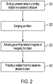
- FIG. 2 is a flow diagram illustrating an approach for fracturing a structure in a controlled, triggerable manner in accordance with some embodiments.
- At least one pressure device is bonded 210 to a surface of the structure.
- the pressure device may be a compact modular self-contained unit that can be attached to the frangible glass structure by a bonding agent, such as an adhesive, as previously discussed.
- the pressure device includes a vessel having a gas-emitting material disposed therein.
- An electrical initiator arranged to activate the gas-emitting material is energized 220 with an electrical current, resulting in activation 230 of a gas-emitting material.
- the electrical current flowing through the resistive bridge heats the bridge to a high temperature.
- the heated bridge e.g., a small, low-cost Ni-chrome wire, activates the gas-emitting material.
- Both the gas-emitting material and the initiator are confined within the small localized interior space of the vessel attached to the glass.
- gases are rapidly generated by the activated gas-emitting material producing 240 a localized pressure in the area of the bonding location. The rapid pressure build-up at bonding location causes the structure to fracture.
- the temperature rise caused by electrical current flowing through the heater bridge alone is insufficient to activate the gas-emitting material.
- the heater bridge is coated with a pyrogenic material that can be ignited at a lower threshold temperature. Electrical current causes the heater bridge to ignite the pyrogenic material, which then burns at a high temperature to activate the gas-emitting material.
- Energizing the initiator may comprise connecting an electrical source to the initiator such that the electrical source produces an electrical current through the initiator.
- Initiators may be energized using simple 9V alkaline batteries, for example, or with voltage sources of as low as 0.1 V supplying electrical currents of about 100 mA. In implementations where ease of handling is important, the typical source voltages are 6 to 12 V supplying currents of 2 to 4 amps. Typical portable sources could be Alkaline or Lithium-based batteries.
- the initiator may be remotely energized, or may be energized when a timer circuit reaches a predetermined time or elapsed time.
- FIGS. 3 and 4 illustrate vessels 321, 421 suitable for use in a pressure device in accordance with various configurations.
- the vessels a321, 421 are designed to withstand the impact pressure of the rapidly released gases that occurs upon activation of the gas-emitting material.
- FIG. 3 illustrates a vessel 321 suitable for use in a pressure device in accordance with some configurations.
- the vessel 321 is a unitary structure that can be fabricated by subtractive, additive, and/or deformative manufacturing processes to remove, add, and/or deform the material of the vessel 321 such that the vessel 321 includes the interior space 323 and bonding surface 322.
- vessel 321 may be fabricated from a relatively thick solid piece by removing material, e.g., by milling, and/or cutting to form the interior space 323 and/or bonding surface 322.
- Additive manufacturing processes that can optionally be used to form the vessel 321 include molding and/or printing.
- the vessel 321 may be molded by an injection molding process or other molding processes.
- the vessel 321 may formed from a relatively thinner solid piece by stamping or otherwise deforming the original piece to form the interior space 323 and/or the bonding surface 322.
- the vessel 421 may comprise several pieces 421a, 421b that are bonded together by a bonding agent 429.
- Vessel 421 may be formed by first piece 421a having a through hole 427 and a second piece 421b that is bonded to the first piece 421a forming a cover for the hole 427 in the first piece 421a.
- the first and second pieces 421a, 421b may be made by any suitable manufacturing process such as water-jet cutting, laser cutting, or processes including those previously discussed in connection with FIG. 3 , e.g., milling, cutting, stamping, molding, printing, etc.
- the bonding agent 429 may be the same as or different from the bonding material used to bond the vessel to the structure.
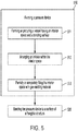
- FIG. 5 is a flow diagram of a method of making an apparatus as illustrated in FIGS. 1A and 1B .
- pressure devices used to fracture glass structures include vessels constructed of low-cost laser-cut acrylic materials or water-jet-cut aluminum. The vessels themselves can be designed to withstand the impact pressure upon activation of the gas-emitting material.
- the apparatus is configured such that activation of the pressure device destroys the structure by causing the structure to fracture.
- the method involves forming 510 a pressure device and bonding 520 the pressure device to the surface of a structure.
- Forming 510 the pressure device includes fabricating or otherwise providing 511 a vessel having an interior space and a bonding surface.
- An initiator is arranged 512 within the interior space of the vessel and may be affixed in the interior space. The wires of the initiator may extend through a wall of the vessel.
- the initiator may be pre-coated with a gas-emitting material before it is arranged within the interior space of the vessel.
- the interior space is partially or completely filled with one or more additional gas-emitting materials 513.
- the gas-emitting material used to partially or completely fill the interior space may be the same as or different from the gas-emitting material that coats the initiator.
- step 513 may be optional and can be eliminated.
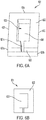
- FIGS. 6A through 6E are a series of diagrams that illustrate formation of a pressure device 620 in accordance with some embodiments.
- FIG. 6A shows a two-piece vessel 621 comprising first and second pieces 621a, 621b similar to the configuration shown in FIG. 4 .
- the vessel 621 has an interior space 623 and bonding surface 622.
- the interior space 623 is defined by the interior surfaces of the walls 625 and back 626 of the vessel 621.
- the front of the vessel 621 is open in this example.
- One wall 625 of the vessel 621 includes a channel 621c that provides a pass through for wires of the initiator.
- the vessel 621 has outer dimensions of 25 mm x 18 mm with wall thickness of 5 mm as illustrated in FIG.
- the thickness of the vessel 621 may be about 5 mm. These specific dimensions are provided for illustration only; the vessel 621 and features thereof 622, 623, 625, 626, 621a, 621b, 621c can have any dimensions that provide for a bonding force greater than a fracture limit of a structure being fractured.
- the ratio of the surface area of the bonding surface to the volume of the interior space is greater than about 0.05 cm -1 . In some embodiments, the ratio of the surface area of the bonding surface to the volume of the interior space is greater than about 0.6 cm -1 and less than about 5 cm -1 .
- FIG. 6C illustrates the pressure device 620 after the initiator 630 is placed inside the interior space 623 of the vessel 621.
- One wall 625 of the vessel 621 includes a channel 621c providing a pass through for wires 631 of the initiator 630.
- the wires 631 are electrically connected by a bridge 632 which optionally has a pyrogenic material disposed thereon.
- FIG. 6D illustrates the process of filling the interior space 623 with the gas-emitting material 624.
- FIG. 6E shows the completed pressure device 620. In embodiments where bridge 632 has gas-emitting materials disposed there-on, the step illustrated in Figure 6D may be omitted.
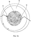
- FIGS. 7A and 7B illustrate fabrication of an apparatus that includes a pressure device in accordance with one example.
- the structure is a glass buoy meant to be deployed in the ocean.
- the buoy can be remotely scuttled when it is no longer needed.
- the buoy is made of a glass bowl that is bonded to a planar top plate cover to form an enclosure.
- the enclosure contains sensors, control electronics, optical components, and radio communication devices.
- FIG. 7A shows two pressure devices 720 such as those described herein bonded to an inside surface of glass bowl 710 of the buoy.
- the glass bowl 710 is partially filled with concrete 780 that functions as ballast.
- an optional additional amount of concrete 781 is added as a backing material that partially covers the pressure devices 710 and further bonds the pressure devices 720 to the bowl 710.
- the buoy is not entirely made of glass.
- the enclosure can be mostly plastic or metal that is outfitted with a glass window.
- the pressure device is bonded on the glass window. Activation of the pressure device causes the glass window to fracture, thereby breaching the enclosure and causing the buoy to sink.
- the gas-emitting material within the pressure devices is activated causing a rapid expansion of gas that produces a force sufficient to fracture the buoy causing it to sink.
- the structure fractured by activation of the pressure device may break in to small fragments, e.g., fragments that have length, width, and height dimensions of less than about 10 mm, 900 ⁇ m, less than about 500 ⁇ m, or even less than about 100 ⁇ m.
- Pressure devices used to fracture glass structures include vessels constructed of low-cost laser-cut acrylic , water-jet aluminum, or stamped metal.
- the vessels can be designed to withstand the impact pressure upon trigger. Unlike most mechanical approaches, the disclosed approach is stable against unintentional trigger.
Landscapes
- Engineering & Computer Science (AREA)
- General Engineering & Computer Science (AREA)
- Manufacturing & Machinery (AREA)
- Chemical & Material Sciences (AREA)
- Combustion & Propulsion (AREA)
- Mechanical Engineering (AREA)
- Ocean & Marine Engineering (AREA)
- Lining Or Joining Of Plastics Or The Like (AREA)
- Disintegrating Or Milling (AREA)
- Air Bags (AREA)
- Processing Of Solid Wastes (AREA)
Abstract
Description
- This disclosure relates generally to devices comprising self-destructing structures and to related methods and systems.
- Systems capable of physically self-destructing in a controlled, triggerable manner are useful in a variety of applications, such as reducing waste, maintaining supply chain integrity, and/or recycling waste products.
- Some embodiments are directed to an apparatus that includes a pressure device bonded to the surface of a structure at a bonding location. The vessel comprises an interior space within the vessel and a bonding surface. A bonding agent bonds the bonding surface of the vessel to a surface of the structure. A gas-emitting material is disposed within the interior space of the vessel and an initiator is arranged to activate the gas-emitting material. Upon activation of the gas-emitting material by the initiator, the pressure device produces a localized force that breaks the structure.
- According to some embodiments, a pressure device includes a vessel having an interior space and a bonding surface configured to provide for bonding of the vessel to a surface of a structure. The pressure device further includes a gas-emitting material disposed within the interior space and an initiator arranged to activate the gas-emitting material. When bonded to the structure, the pressure device is configured to produce a localized force that breaks the structure in response to activation of the gas-emitting material by the initiator.
- Some embodiments involve a method in which a pressure device is bonded to a bonding location on a surface of a structure. The pressure device comprises a vessel including an interior space and a bonding surface, a gas-emitting material disposed within the interior space, and an initiator arranged to activate the gas-emitting material. The initiator is energized and, in response to energizing the initiator, the gas-material is activated. Activation of the gas-emitting material produces a localized force that causes the structure to break.
- Some embodiments are directed to a method of fabricating an apparatus. An interior space of a vessel is partially or fully filled with a gas-emitting material. An initiator is arranged in proximity to the gas-emitting material. The vessel is bonded to a surface of a structure with a bonding force sufficient to withstand pressure generated in response to activation of the gas-emitting material by the initiator.
-
-
FIGS. 1A shows a side cross sectional view of a portion of an apparatus in accordance with some embodiments; -
FIG. 1B shows a bottom view of the apparatus ofFIG. 1A without the gas-emitting material and from the perspective of looking through a clear structure; -
FIG. 2 is a flow diagram illustrating an approach for fracturing a structure in a controlled, triggerable manner in accordance with some embodiments; -
FIG. 3 illustrates a vessel suitable for use in a pressure device in accordance with some configurations; -
FIG. 4 depicts a multi-piece vessel suitable for use in a pressure device in accordance with some configurations; -
FIG. 5 is a flow diagram of a method of making an apparatus in accordance with some embodiments; -
FIGS. 6A through 6E are a series of diagrams that illustrate formation of a pressure device in accordance with some embodiments; and -
FIGS. 7A and7B illustrate fabrication of an apparatus that includes a pressure device in accordance with one example. - The figures are not necessarily to scale. Like numbers used in the figures refer to like components. However, it will be understood that the use of a number to refer to a component in a given figure is not intended to limit the component in another figure labeled with the same number.
- Embodiments disclosed herein relate to approaches for fracturing structures into smaller pieces in a controlled, triggerable manner. Frangible glass structures, especially when tempered; e.g., by chemical ion-exchange or by thermal quenching, are structurally very strong and become increasingly difficult to fracture with increasing thickness. Many applications require the robustness or stiffness of thicker glass. As discussed below, devices capable of reliably and controllably fracturing the thick structures include pressure devices with electrical initiators. The pressure devices disclosed herein can be physically small and light weight yet provide mechanical and operational robustness that avoids unintentional triggering.
- According to some implementations, the controlled fracturing can reduce the volume of waste at the end of a structure's useful life and/or can facilitate recycling the structure materials. The disclosed approaches can be used for fragmentation and/or destruction of various planar and 3D structures, such as mechanical parts, enclosures, aerospace components, windows, ocean buoys, electronic substrates, among other structures.
-
FIG. 1A shows a side cross sectional view of a portion of anapparatus 100 in accordance with some embodiments. Theapparatus 100 includes astructure 110 to which apressure vessel 120 is mounted.FIG. 1B shows a bottom view of theapparatus 100 from the perspective of looking through aclear structure 110. The gas-emittingmaterial 124 shown inFIG. 1A is absent inFIG. 1B . Thestructure 110 may be any type of structure and have any suitable geometrical configuration. In various implementations, thestructure 110 may be made of a brittle or frangible material such as glass, ceramic, plastic, laminated fillers of wood, metal or gypsum, clay, porcelain, and/or metal. Although thestructure 110 may be complex and include many different materials and shapes, the frangible material may be disposed at least at thebonding location 115 where thepressure device 120 is bonded to thestructure 110. - In many embodiments, the
structure 110 is glass. A glass structure can comprise one or more of cast glass, slumped glass, untempered glass, tempered glass, thermally tempered glass, ion-exchanged glass, soda-lime glass, lead glass, borosilicate glass, aluminosilicate glass, alkali-aluminosilicate glass, silica glass, and sodium-rich glass. Thepressure device 120 can be configured to fracture a glass structure that is more than about 0.5 mm thick at thebonding location 115 of thestructure 110. For example, the thickness of thestructure 110 at thebonding location 115 may be about 1 mm thick, about 2mm thick or even greater than 2 mm thick. - The
pressure device 120 comprises avessel 121 having abonding surface 122 and aninterior space 123. Thebonding surface 122 bonds thevessel 121 to asurface 111 of thestructure 110 at abonding location 115 of thestructure 110. Abonding agent 140 is disposed between thebonding surface 122 of thevessel 121 and thesurface 111 of thestructure 110 at thebonding location 115. Thevessel 121 may be made of a material comprising one or more of a metal, acrylic, plastic, rubber, ceramic, cement, thermoplastic, compacted sand, wood, and glass, for example. Thebonding agent 140 may comprise one or more of various types of epoxies, cyanoacrylates, structural adhesives, steel-reinforced adhesives, silicone, thermoset plastics, acrylic, urethane, UV curable adhesives, ethylene vinyl acetate, solder, welding interface material, and construction adhesives. - The
bonding agent 140 and thebonding surface 122 are configured to bond thevessel 121 to thebonding location 115 on thesurface 111 of thestructure 110 with a bonding force greater than a fracture limit of thestructure 110 over across-sectional area 199 bounded by aninner perimeter 125 of theinterior space 123 of thevessel 121 at thebonding surface 122.. The fracture limit is the force at which thestructure 110 fractures. In some implementations, the fracture limit of thestructure 110 at thebonding location 115 may be greater than about 5 MPa. - According to some implementations, an
optional backing material 150 may be disposed at least partially over thevessel 121. For example, as shown inFIG. 1A , thebacking material 150 may be disposed oversurfaces 127 of thevessel 121 opposite and/or adjacent to thebonding surface 122. Thebacking material 150 bonds thevessel 121 to thesurface 111 of thestructure 110 and may work in conjunction with thebonding agent 140 to hold thepressure vessel 120 against thestructure 110. Suitable materials for thebacking material 150 may comprise at least one of concrete, structural adhesives, and an epoxy potting compound, for example. - A gas-emitting
material 124, comprising chemical compounds such as potassium nitrate, sodium azide, ammonium perchlorate, ammonium nitrate, or ammonium dinitramide, is contained within theinterior space 123 of thevessel 121. In some embodiments, after thevessel 121 is bonded to thesurface 111, the gas-emittingmaterial 124 is in contact with or in close proximity to one or both of thesurface 111 of thestructure 110 and the interior surface of thevessel 121. Anelectrical initiator 130 is arranged to activate the gas-emittingmaterial 124. In other embodiments, the gas-emittingmaterial 124 is in contact or in close proximity to theelectrical initiator 130 but not in contact with eithersurface 111 of thestructure 110 or the interior surface ofvessel 121. Gas-emittingmaterial 124 may occupy a very small percentage of the volume ofinterior space 123 or may fully fill theinterior space 123. As shown inFIGS. 1A and 1B , theinitiator 130 may be disposed within theinterior space 123 of thevessel 121 and/or may be arranged to be in contact with the gas-emittingmaterial 124. For example, theinitiator 130 can be embedded within the gas-emittingmaterial 123 in some implementations with leads (wires 131) extending from thevessel 121 as shown inFIGS. 1A and 1B . - The
electrical initiator 130 is energized by a current flowing through a pair of electricallyconductive wires 131 that are electrically connected by an electricallyconductive bridge 132. In some implementations, thebridge 132 comprises a material having a higher electrical resistance than thewires 131. For example, thebridge 132 may be a nichrome alloy and thewires 131 may be copper or aluminum. According to some implementations, the bridge132 and/or thewires 131 are coated with a pyrogenic material. The pyrogenic material coating thebridge 132 and/orwires 131 may be the same as or different from the gas-emittingmaterial 124 that is disposed within theinterior space 123 of thevessel 121. The pyrogenic coating enhances the heat from theelectrical bridge 132 to more effectively activate the gas-emittingmaterial 124. - When
initiator 130 is energized by an electric current flowing through the electricallyconductive elements initiator 130, the gas-emittingmaterial 124 is heated by thewires 131,bridge 132 and/or additional pyrogenic material coating thewires 131 and/or bridge 132 to an activation temperature of the gas-emittingmaterial 124. Activation of the gas-emittingmaterial 124 causes a rapid release of gas. The rapid release of gas within thevessel 121, which is tightly bonded to thesurface 111 of thestructure 110, produces a localized pressure that breaks thestructure 110. - As best seen in
FIG. 1A , in some embodiments theapparatus 100 includes acurrent source 160, such as a battery, configured to supply the electrical current to theinitiator 130. Aswitch 161 electrically connects thesource 160 to theinitiator 130. In some implementations, the switch 161 (shown inFIG. 1A ) can be remotely controlled allowing fracture of thestructure 110 to be triggered from a location remote from thestructure 110. In such an embodiment, a wireless signal activates theswitch 161 to connect thecurrent source 160 to theinitiator 130. In some implementations, theswitch 161 is a MOSFET transistor that can be turned on or off by applying a bias voltage at the transistor's gate. In another implementation, theswitch 161 is a silicon-controlled rectifier that can be turned on by applying a small current at one of its terminals. In yet another implementation, theswitch 161 can be a mechanical relay switch. -
FIG. 2 is a flow diagram illustrating an approach for fracturing a structure in a controlled, triggerable manner in accordance with some embodiments. At least one pressure device is bonded 210 to a surface of the structure. The pressure device may be a compact modular self-contained unit that can be attached to the frangible glass structure by a bonding agent, such as an adhesive, as previously discussed. The pressure device includes a vessel having a gas-emitting material disposed therein. An electrical initiator arranged to activate the gas-emitting material is energized 220 with an electrical current, resulting inactivation 230 of a gas-emitting material. The electrical current flowing through the resistive bridge heats the bridge to a high temperature. The heated bridge, e.g., a small, low-cost Ni-chrome wire, activates the gas-emitting material. Both the gas-emitting material and the initiator are confined within the small localized interior space of the vessel attached to the glass. When the gas-emitting material is activated by the initiator, gases are rapidly generated by the activated gas-emitting material producing 240 a localized pressure in the area of the bonding location. The rapid pressure build-up at bonding location causes the structure to fracture. - In some implementations, the temperature rise caused by electrical current flowing through the heater bridge alone is insufficient to activate the gas-emitting material. The heater bridge is coated with a pyrogenic material that can be ignited at a lower threshold temperature. Electrical current causes the heater bridge to ignite the pyrogenic material, which then burns at a high temperature to activate the gas-emitting material.
- Energizing the initiator may comprise connecting an electrical source to the initiator such that the electrical source produces an electrical current through the initiator. Initiators may be energized using simple 9V alkaline batteries, for example, or with voltage sources of as low as 0.1 V supplying electrical currents of about 100 mA. In implementations where ease of handling is important, the typical source voltages are 6 to 12 V supplying currents of 2 to 4 amps. Typical portable sources could be Alkaline or Lithium-based batteries. In some configurations, the initiator may be remotely energized, or may be energized when a timer circuit reaches a predetermined time or elapsed time.
-
FIGS. 3 and 4 illustratevessels -
FIG. 3 illustrates avessel 321 suitable for use in a pressure device in accordance with some configurations. Thevessel 321 is a unitary structure that can be fabricated by subtractive, additive, and/or deformative manufacturing processes to remove, add, and/or deform the material of thevessel 321 such that thevessel 321 includes theinterior space 323 andbonding surface 322. - For example, in some implementations,
vessel 321 may be fabricated from a relatively thick solid piece by removing material, e.g., by milling, and/or cutting to form theinterior space 323 and/orbonding surface 322. Additive manufacturing processes that can optionally be used to form thevessel 321 include molding and/or printing. For example, thevessel 321 may be molded by an injection molding process or other molding processes. As an example of a deformative fabrication process, thevessel 321 may formed from a relatively thinner solid piece by stamping or otherwise deforming the original piece to form theinterior space 323 and/or thebonding surface 322. - In some embodiments, as illustrated in
FIG. 4 , thevessel 421 may compriseseveral pieces bonding agent 429.Vessel 421 may be formed byfirst piece 421a having a throughhole 427 and asecond piece 421b that is bonded to thefirst piece 421a forming a cover for thehole 427 in thefirst piece 421a. The first andsecond pieces FIG. 3 , e.g., milling, cutting, stamping, molding, printing, etc.. Thebonding agent 429 may be the same as or different from the bonding material used to bond the vessel to the structure. -
FIG. 5 is a flow diagram of a method of making an apparatus as illustrated inFIGS. 1A and 1B . According to some embodiments, pressure devices used to fracture glass structures include vessels constructed of low-cost laser-cut acrylic materials or water-jet-cut aluminum. The vessels themselves can be designed to withstand the impact pressure upon activation of the gas-emitting material. The apparatus is configured such that activation of the pressure device destroys the structure by causing the structure to fracture. - The method involves forming 510 a pressure device and
bonding 520 the pressure device to the surface of a structure. Forming 510 the pressure device includes fabricating or otherwise providing 511 a vessel having an interior space and a bonding surface. An initiator is arranged 512 within the interior space of the vessel and may be affixed in the interior space. The wires of the initiator may extend through a wall of the vessel. The initiator may be pre-coated with a gas-emitting material before it is arranged within the interior space of the vessel. The interior space is partially or completely filled with one or more additional gas-emittingmaterials 513. The gas-emitting material used to partially or completely fill the interior space may be the same as or different from the gas-emitting material that coats the initiator. In embodiments where the initiator is pre-coated with gas-emitting material,step 513 may be optional and can be eliminated. -
FIGS. 6A through 6E are a series of diagrams that illustrate formation of apressure device 620 in accordance with some embodiments.FIG. 6A shows a two-piece vessel 621 comprising first andsecond pieces FIG. 4 . Thevessel 621 has aninterior space 623 andbonding surface 622. Theinterior space 623 is defined by the interior surfaces of thewalls 625 and back 626 of thevessel 621. The front of thevessel 621 is open in this example. Onewall 625 of thevessel 621 includes achannel 621c that provides a pass through for wires of the initiator. In one particular example, thevessel 621 has outer dimensions of 25 mm x 18 mm with wall thickness of 5 mm as illustrated inFIG. 6B . The thickness of the vessel 621may be about 5 mm. These specific dimensions are provided for illustration only; thevessel 621 and features thereof 622, 623, 625, 626, 621a, 621b, 621c can have any dimensions that provide for a bonding force greater than a fracture limit of a structure being fractured. - In some embodiments, the ratio of the surface area of the bonding surface to the volume of the interior space is greater than about 0.05 cm-1. In some embodiments, the ratio of the surface area of the bonding surface to the volume of the interior space is greater than about 0.6 cm-1 and less than about 5 cm-1.
-
FIG. 6C illustrates thepressure device 620 after theinitiator 630 is placed inside theinterior space 623 of thevessel 621. Onewall 625 of thevessel 621 includes achannel 621c providing a pass through forwires 631 of theinitiator 630. Thewires 631 are electrically connected by abridge 632 which optionally has a pyrogenic material disposed thereon.FIG. 6D illustrates the process of filling theinterior space 623 with the gas-emittingmaterial 624.FIG. 6E shows the completedpressure device 620. In embodiments wherebridge 632 has gas-emitting materials disposed there-on, the step illustrated inFigure 6D may be omitted. -
FIGS. 7A and7B illustrate fabrication of an apparatus that includes a pressure device in accordance with one example. In this particular illustration, the structure is a glass buoy meant to be deployed in the ocean. The buoy can be remotely scuttled when it is no longer needed. The buoy is made of a glass bowl that is bonded to a planar top plate cover to form an enclosure. The enclosure contains sensors, control electronics, optical components, and radio communication devices.FIG. 7A shows twopressure devices 720 such as those described herein bonded to an inside surface ofglass bowl 710 of the buoy. Theglass bowl 710 is partially filled withconcrete 780 that functions as ballast. After thepressure devices 720 are bonded to the glass bowl by a bonding agent, an optional additional amount ofconcrete 781 is added as a backing material that partially covers thepressure devices 710 and further bonds thepressure devices 720 to thebowl 710. - In some implementations,, the buoy is not entirely made of glass. The enclosure can be mostly plastic or metal that is outfitted with a glass window. In such implementation, the pressure device is bonded on the glass window. Activation of the pressure device causes the glass window to fracture, thereby breaching the enclosure and causing the buoy to sink.
- When the initiators within the pressure devices are energized, the gas-emitting material within the pressure devices is activated causing a rapid expansion of gas that produces a force sufficient to fracture the buoy causing it to sink. In some embodiments, the structure fractured by activation of the pressure device may break in to small fragments, e.g., fragments that have length, width, and height dimensions of less than about 10 mm, 900 µm, less than about 500 µm, or even less than about 100 µm.
- Pressure devices used to fracture glass structures include vessels constructed of low-cost laser-cut acrylic , water-jet aluminum, or stamped metal. The vessels can be designed to withstand the impact pressure upon trigger. Unlike most mechanical approaches, the disclosed approach is stable against unintentional trigger.
- Unless otherwise indicated, all numbers expressing feature sizes, amounts, and physical properties used in the specification and claims are to be understood as being modified in all instances by the term "about." Accordingly, unless indicated to the contrary, the numerical parameters set forth in the foregoing specification and attached claims are approximations that can vary depending upon the desired properties sought to be obtained by those skilled in the art utilizing the teachings disclosed herein. The use of numerical ranges by endpoints includes all numbers within that range (e.g. 1 to 5 includes 1, 1.5, 2, 2.75, 3, 3.80, 4, and 5) and any range within that range.
- Various modifications and alterations of the embodiments discussed above will be apparent to those skilled in the art, and it should be understood that this disclosure is not limited to the illustrative embodiments set forth herein. The reader should assume that features of one disclosed embodiment can also be applied to all other disclosed embodiments unless otherwise indicated. It should also be understood that all U.S. patents, patent applications, patent application publications, and other patent and non-patent documents referred to herein are incorporated by reference, to the extent they do not contradict the foregoing disclosure.
Claims (38)
- An apparatus comprising:a structure;a pressure device comprising:a vessel bonded to a surface of the structure at a bonding location, the vessel having an interior space within the vessel and a bonding surface;a gas-emitting material disposed within the interior space; andan initiator arranged to activate the gas-emitting material; anda bonding agent that bonds the bonding surface of the vessel to a surface of the structure, wherein upon activation of the gas-emitting material by the initiator, the pressure device is configured to produce a localized force that breaks the structure.
- The apparatus of claim 1, wherein the bonding agent and the bonding surface are configured to bond the vessel to a bonding location of the surface with a bonding force greater than a fracture limit of the structure over a cross-sectional area of an inner perimeter of the vessel at the bonding location.
- The apparatus of claim 2, wherein the fracture limit of the structure is greater than about 5 MPa.
- The apparatus of claim 1, wherein a portion or all of the structure is glass.
- The apparatus of claim 4, wherein the glass is more than 0.5 mm thick at the bonding location.
- The apparatus of claim 4, wherein the glass comprises one or more of cast glass, slumped glass, untempered glass, tempered glass, thermally tempered glass, ion-exchanged glass, soda-lime glass, lead glass, borosilicate glass, aluminosilicate glass, alkali-aluminosilicate glass, silica glass, and sodium-rich glass.
- The apparatus of claim 1, wherein a portion or all of the structure is made of clay, porcelain, plastic, laminated fillers of metal, wood, or gypsum.
- The apparatus of claim 1, wherein the structure is one of ocean buoy, enclosure, aerospace component, mechanical part, window, electronic substrate
- The apparatus of claim 1, wherein the bonding agent comprises one or more of an epoxy, cyanoacrylate, structural adhesive, steel-reinforced adhesive, silicone, thermoset plastic, acrylic, urethane, UV curable adhesive, ethylene vinyl acetate, solder, welding interface materials, and construction adhesive.
- The apparatus of claim 1, further comprising a backing material disposed over a surface of the vessel opposite the bonding surface.
- The apparatus of claim 10, wherein the backing material comprises at least one of concrete and an epoxy potting compound.
- The apparatus of claim 10, wherein the backing material bonds the vessel to the surface of the structure.
- The apparatus of claim 1, further comprising an electrical source configured to deliver an electrical current through the initiator.
- The apparatus of claim 13, wherein electrical current is delivered through a switch.
- The apparatus of claim 14, wherein the switch is one of MOSFET transistor, silicon-controlled rectifier, mechanical switch, mechanical relay switch.
- The apparatus of claim 13, wherein the electrical source is a battery.
- A pressure device comprising:a vessel having an interior space and a bonding surface configured to provide for bonding of the vessel to a surface of a structure;a gas-emitting material disposed within the space; andan initiator arranged to activate the gas-emitting material, wherein when bonded to the structure, the pressure device is configured to produce a localized force that breaks the structure in response to activation of the gas-emitting material by the initiator.
- The pressure device of claim 17, wherein when the vessel is bonded to a surface of the structure by a bonding agent at a bonding location, the bonding surface is configured to provide a bonding force greater than a fracture limit of the structure over a cross-sectional area of an inner perimeter of the vessel at the bonding location.
- The pressure device of claim 17, wherein the bonding surface is configured provide for bonding the vessel to a bonding location of the surface with a bonding force greater than 5 MPa.
- The pressure device of claim 17, wherein a ratio of a surface area of the bonding surface to a volume of the interior space is greater than about 0.05 cm-1 .
- The pressure device of claim 17, wherein ratio of the surface area of the bonding surface to the volume of the interior space is greater than about 0.6 cm-1 and less than about 5 cm-1.
- The pressure device of claim 17, wherein the vessel material comprises one or more of a metal, plastic, rubber, ceramic, cement, thermoplastic, compacted sand, wood, glass
- The pressure device of claim 17, wherein the vessel comprises:a first layer;a hole through the first layer that includes the bonding surface; anda second layer bonded to the first layer, wherein the interior space of the vessel is bounded by sides of the hole and the second layer.
- The pressure device of claim 17, wherein the vessel comprises a single layer having the interior space disposed within the single layer.
- The pressure device of claim 17 wherein the vessel is stamped metal.
- The pressure device of claim 17, wherein the vessel includes an opening to the interior space and the opening is configured to be covered by the surface of the structure when the vessel is bonded to the structure at the bonding location.
- The pressure device of claim 17, wherein the initiator is an electrical initiator.
- The pressure device of claim 27, wherein the electrical initiator comprises:a pair of electrically conductive wires; andan electrically conductive bridge between the wires, the bridge comprising a material having a higher electrical resistance than the wires.
- The pressure device of claim 28, wherein the bridge is coated with a pyrogenic material.
- The pressure device of claim 28, wherein the bridge comprises a nichrome alloy.
- The pressure device of claim 17, wherein the gas-emitting material comprises one of potassium nitrate, sodium azide, ammonium perchlorate, ammonium nitrate, ammonium dinitramide.
- A method comprising:bonding a pressure device to a bonding location on a surface of a structure, the pressure device comprising:a vessel including an interior space and a bonding surfacea gas-emitting material disposed within the interior space; andan initiator arranged to activate the gas-emitting material;energizing the initiator; andactivating the gas-emitting material in response to energizing the initiator, activation of the gas-emitting material producing a localized force that causes the structure to break.
- The method of claim 32, wherein bonding the pressure device comprises bonding the pressure device to a bonding location of the surface with a bonding force greater than a fracture limit of the structure over a cross-sectional area of an inner perimeter of the vessel at the bonding location.
- The method of claim 32 wherein energizing the initiator comprises connecting an electrical source to the initiator, the electrical source producing an electrical current through the initiator.
- A method of fabricating an apparatus, comprising:arranging an initiator in proximity to the gas-emitting material;filling an interior space of a vessel with a gas-emitting material;
bonding the vessel having the gas-emitting material and initiator disposed within the interior space to a surface of a structure with a bonding force sufficient to withstand pressure generated in response to activation of the gas-emitting material by the initiator. - The method of claim 35, further comprising forming the vessel.
- The method of claim 36, wherein forming the vessel comprises:cutting a hole in a first layer material; andbonding a second layer of material to the first layer such that the interior space of the vessel is bounded by sides of the hole and the second layer.
- The method of claim 36, wherein forming the vessel comprises milling or stamping a layer of material to form the interior space of the vessel.
Applications Claiming Priority (1)
| Application Number | Priority Date | Filing Date | Title |
|---|---|---|---|
| US16/403,131 US10969205B2 (en) | 2019-05-03 | 2019-05-03 | Electrically-activated pressure vessels for fracturing frangible structures |
Publications (2)
| Publication Number | Publication Date |
|---|---|
| EP3741657A2 true EP3741657A2 (en) | 2020-11-25 |
| EP3741657A3 EP3741657A3 (en) | 2021-02-17 |
Family
ID=70476091
Family Applications (1)
| Application Number | Title | Priority Date | Filing Date |
|---|---|---|---|
| EP20171951.5A Withdrawn EP3741657A3 (en) | 2019-05-03 | 2020-04-28 | Electrically-activated pressure vessels for fracturing frangible structures |
Country Status (3)
| Country | Link |
|---|---|
| US (1) | US10969205B2 (en) |
| EP (1) | EP3741657A3 (en) |
| JP (1) | JP7362540B2 (en) |
Cited By (2)
| Publication number | Priority date | Publication date | Assignee | Title |
|---|---|---|---|---|
| EP4015408A1 (en) * | 2020-12-21 | 2022-06-22 | Palo Alto Research Center Incorporated | Triggerable mechanisms and fragment containment arrangements for self-destructing frangible structures and sealed vessels |
| EP4015407A1 (en) * | 2020-12-21 | 2022-06-22 | Palo Alto Research Center Incorporated | Mechanical triggers and triggering methods for self-destructing frangible structures and sealed vessels |
Family Cites Families (105)
| Publication number | Priority date | Publication date | Assignee | Title |
|---|---|---|---|---|
| US1839884A (en) * | 1929-08-27 | 1932-01-05 | Gen Fire Extinguisher Co | Frangible vessel and method of making the same |
| US2529210A (en) | 1947-05-23 | 1950-11-07 | Joseph F Butler | Cutting apparatus for wallboards and the like |
| GB1138401A (en) | 1965-05-06 | 1969-01-01 | Mallory & Co Inc P R | Bonding |
| US3601114A (en) | 1969-01-21 | 1971-08-24 | Norton Co | Method and apparatus for cutting complex shapes |
| US3673667A (en) | 1970-11-23 | 1972-07-04 | Whittaker Corp | Method for producing complex shapes by filled billet extrusion |
| US3666967A (en) | 1971-05-12 | 1972-05-30 | Us Navy | Self-destruct aluminum-tungstic oxide films |
| US3882323A (en) | 1973-12-17 | 1975-05-06 | Us Navy | Method and apparatus for protecting sensitive information contained in thin-film microelectonic circuitry |
| CA1064333A (en) | 1976-11-30 | 1979-10-16 | Her Majesty The Queen In Right Of Canada As Represented By The Minister Of National Defence Of Her Majesty's Canadian Government | Scuttling method for marine markers |
| US4102664A (en) | 1977-05-18 | 1978-07-25 | Corning Glass Works | Method for making glass articles with defect-free surfaces |
| US4139359A (en) | 1977-11-02 | 1979-02-13 | Ppg Industries, Inc. | Method and apparatus for shaping glass sheets by roll forming |
| DE3230554C2 (en) | 1982-04-28 | 1984-07-26 | GTI Glastechnische Industrie Peter Lisec, GmbH, Amstetten | Method and device for cutting laminated glass |
| SE435352B (en) | 1983-05-04 | 1984-09-24 | Hydro Betong Ab | CONSTRUCTION BODY FOR A PREPARED CONSTRUCTION CONSISTING OF A NUMBER WITH OTHER COMBINED PLASTICS OF PLASTIC MATERIAL, OF EXV URETANCUM AND SET TO MAKE SAID BODY |
| GB8322258D0 (en) | 1983-08-18 | 1983-09-21 | Holmes A | Security and protection screens |
| US4558622A (en) | 1983-11-04 | 1985-12-17 | Russell Tausheck | Apparatus for cutting laminated glass |
| DE3682681D1 (en) * | 1985-05-28 | 1992-01-09 | Explosive Dev Ltd | METHOD AND DEVICE FOR CUTTING WITH EXPLOSIVES. |
| US4739555A (en) | 1985-06-18 | 1988-04-26 | Werner Jurgens | Laminated glass cutter |
| FR2681472B1 (en) | 1991-09-18 | 1993-10-29 | Commissariat Energie Atomique | PROCESS FOR PRODUCING THIN FILMS OF SEMICONDUCTOR MATERIAL. |
| GB9201863D0 (en) | 1992-01-29 | 1992-03-18 | Dunn Kenneth R | Multi glazing air cushion release unit |
| JPH0938950A (en) * | 1995-07-31 | 1997-02-10 | Hitachi Zosen Corp | Destruction device for objects to be destroyed |
| US6327978B1 (en) * | 1995-12-08 | 2001-12-11 | Kaman Aerospace Corporation | Exploding thin film bridge fracturing fragment detonator |
| US5791056A (en) | 1996-11-22 | 1998-08-11 | Messina; Gary D. | Emergency glass breaking tool |
| JPH10331446A (en) * | 1997-05-30 | 1998-12-15 | Hitachi Zosen Corp | Discharge impact destruction method and discharge impact destruction device |
| JP3328184B2 (en) * | 1998-03-06 | 2002-09-24 | 日立造船株式会社 | Destruction method |
| WO2000018191A1 (en) * | 1998-09-18 | 2000-03-30 | Marc Seghatol | Microwave polymerization system for dentistry |
| DE19958750B4 (en) | 1999-12-07 | 2006-08-24 | Robert Bosch Gmbh | Leaky wave antenna |
| KR100771258B1 (en) | 2000-05-09 | 2007-10-29 | 가부시키가이샤 한도오따이 에네루기 켄큐쇼 | Identity verification system, identity verification method and mobile phone device |
| US6418628B1 (en) | 2001-03-22 | 2002-07-16 | Task Force Tips, Inc. | Spring-loaded car window breaker and retractable safety sheath |
| FR2823599B1 (en) | 2001-04-13 | 2004-12-17 | Commissariat Energie Atomique | DEMOMTABLE SUBSTRATE WITH CONTROLLED MECHANICAL HOLDING AND METHOD OF MAKING |
| GB0127083D0 (en) | 2001-11-10 | 2002-01-02 | P W Allen & Company Ltd | Device for breaking glass |
| FR2837304B1 (en) | 2002-03-13 | 2004-05-28 | Commissariat Energie Atomique | SECURE ELECTRONIC DEVICE |
| US20040031966A1 (en) | 2002-08-16 | 2004-02-19 | Forrest Stephen R. | Organic photonic integrated circuit using a photodetector and a transparent organic light emitting device |
| JP2004075504A (en) | 2002-08-22 | 2004-03-11 | Nippon Sheet Glass Co Ltd | Method and apparatus for multiply bending glass sheet |
| DE10305733B4 (en) | 2003-02-12 | 2005-10-20 | Saint Gobain Sekurit D Gmbh | Method of producing predetermined breaking points in glass panes, glass pane with weakening zone and use of same |
| JP4115859B2 (en) | 2003-02-28 | 2008-07-09 | 株式会社日立製作所 | Anodic bonding method and electronic device |
| DE10309826B4 (en) | 2003-03-05 | 2009-11-12 | Schott Ag | Process for structuring phosphate glasses by non-destructive ion exchange, structured phosphate glasses and their use |
| US7002517B2 (en) | 2003-06-20 | 2006-02-21 | Anritsu Company | Fixed-frequency beam-steerable leaky-wave microstrip antenna |
| EP1517073A1 (en) | 2003-09-19 | 2005-03-23 | Universita degli Studi di Trento | ESP glass rupture disk |
| EP1671375A4 (en) | 2003-10-09 | 2009-11-25 | Ocas Corp | BOLOMETRIC INFRARED DETECTOR HAVING BILOUCHE STRUCTURE AND METHOD FOR MANUFACTURING THE SAME |
| US20050082331A1 (en) | 2003-10-17 | 2005-04-21 | Chi-Hong Yang | Tempered glass breaker |
| DE102004015546B4 (en) | 2004-03-30 | 2011-05-12 | Infineon Technologies Ag | An integrated circuit semiconductor chip and method for securing a semiconductor integrated circuit |
| US20060270190A1 (en) | 2005-05-25 | 2006-11-30 | The Regents Of The University Of California | Method of transferring a thin crystalline semiconductor layer |
| US20080311686A1 (en) | 2005-08-03 | 2008-12-18 | California Institute Of Technology | Method of Forming Semiconductor Layers on Handle Substrates |
| US7880248B1 (en) | 2005-10-17 | 2011-02-01 | Teledyne Technologies Incorporated | Destructor integrated circuit chip, interposer electronic device and methods |
| KR101389808B1 (en) | 2005-11-18 | 2014-04-29 | 가부시키가이샤 한도오따이 에네루기 켄큐쇼 | Photoelectric conversion device |
| US8168050B2 (en) | 2006-07-05 | 2012-05-01 | Momentive Performance Materials Inc. | Electrode pattern for resistance heating element and wafer processing apparatus |
| US7896988B2 (en) | 2007-06-15 | 2011-03-01 | Spectre Enterprises, Inc. | Charge system for destroying chips on a circuit board and method for destroying chips on a circuit board |
| GB0717489D0 (en) | 2007-09-08 | 2007-10-17 | Design Factor Ni The Ltd | A Glass breaking device |
| US7623560B2 (en) | 2007-09-27 | 2009-11-24 | Ostendo Technologies, Inc. | Quantum photonic imagers and methods of fabrication thereof |
| US8006621B1 (en) * | 2008-02-07 | 2011-08-30 | Cherry Christopher R | Linear explosive breaching apparatus and method |
| JP2009212315A (en) | 2008-03-04 | 2009-09-17 | Elpida Memory Inc | Semiconductor device and manufacturing method thereof |
| US8330191B2 (en) | 2008-06-13 | 2012-12-11 | Nxp B.V. | Intrusion protection using stress changes |
| WO2010016928A2 (en) | 2008-08-08 | 2010-02-11 | Corning Incorporated | Strengthened glass articles and methods of making |
| KR20100063269A (en) | 2008-12-03 | 2010-06-11 | 주식회사 동부하이텍 | Image sensor and method for manufacturing thereof |
| US8089285B2 (en) | 2009-03-03 | 2012-01-03 | International Business Machines Corporation | Implementing tamper resistant integrated circuit chips |
| JP5131933B2 (en) * | 2009-03-31 | 2013-01-30 | 独立行政法人産業技術総合研究所 | Blast treatment method and blast treatment apparatus |
| JP5095658B2 (en) * | 2009-03-31 | 2012-12-12 | 株式会社神戸製鋼所 | Blast treatment method and blast treatment apparatus |
| JP5095656B2 (en) * | 2009-03-31 | 2012-12-12 | 株式会社神戸製鋼所 | Blast treatment method and blast treatment apparatus |
| US8130072B2 (en) | 2009-05-14 | 2012-03-06 | Palo Alto Research Center Incorporated | Vanadium oxide thermal microprobes |
| CN201532635U (en) | 2009-09-03 | 2010-07-21 | 百富计算机技术(深圳)有限公司 | A safety protection device |
| US8946590B2 (en) | 2009-11-30 | 2015-02-03 | Corning Incorporated | Methods for laser scribing and separating glass substrates |
| FR2953213B1 (en) | 2009-12-01 | 2013-03-29 | Saint Gobain | METHOD FOR ION ABRASION SURFACE STRUCTURING, STRUCTURED SURFACE AND USES |
| TWI438162B (en) | 2010-01-27 | 2014-05-21 | Wintek Corp | Cutting method and preparatory cutting structure for reinforced glass |
| US8393175B2 (en) | 2010-08-26 | 2013-03-12 | Corning Incorporated | Methods for extracting strengthened glass substrates from glass sheets |
| AU2011314378A1 (en) | 2010-10-15 | 2013-05-02 | Searete Llc | Surface scattering antennas |
| US8607590B2 (en) | 2010-11-30 | 2013-12-17 | Corning Incorporated | Methods for separating glass articles from strengthened glass substrate sheets |
| US8616024B2 (en) | 2010-11-30 | 2013-12-31 | Corning Incorporated | Methods for forming grooves and separating strengthened glass substrate sheets |
| US8539794B2 (en) | 2011-02-01 | 2013-09-24 | Corning Incorporated | Strengthened glass substrate sheets and methods for fabricating glass panels from glass substrate sheets |
| US20140300520A1 (en) | 2011-04-07 | 2014-10-09 | Polyvalor, Limited Partnership | Full-space scanning end-switched crlh leaky-wave antenna |
| US8695263B2 (en) * | 2011-07-01 | 2014-04-15 | Applied Explosives Technology Pty Limited | Shell destruction technique |
| US8635887B2 (en) | 2011-08-10 | 2014-01-28 | Corning Incorporated | Methods for separating glass substrate sheets by laser-formed grooves |
| TWI415809B (en) | 2011-08-12 | 2013-11-21 | Wintek Corp | Reinforced glass cell and method for fabricating the same and cover glass having the reinforced glass cell |
| US20130082383A1 (en) | 2011-10-03 | 2013-04-04 | Texas Instruments Incorporated | Electronic assembly having mixed interface including tsv die |
| HK1204205A1 (en) | 2011-12-01 | 2015-11-06 | The Board Of Trustees Of The University Of Illinois | Transient devices designed to undergo programmable transformations |
| CN102617022B (en) | 2012-03-31 | 2014-10-22 | 洛阳兰迪玻璃机器股份有限公司 | Machining method for columnar curved toughened glass |
| CN102617023B (en) | 2012-03-31 | 2014-12-31 | 洛阳兰迪玻璃机器股份有限公司 | Machining device for columnar curved toughened glass |
| SE537874C2 (en) | 2012-04-13 | 2015-11-03 | Silex Microsystems Ab | CTE-adapted interposer and method of manufacturing one |
| US20130273717A1 (en) | 2012-04-17 | 2013-10-17 | Taiwan Semiconductor Manufacturing Co., Ltd. | Apparatus and Method for the Singulation of a Semiconductor Wafer |
| US9938180B2 (en) | 2012-06-05 | 2018-04-10 | Corning Incorporated | Methods of cutting glass using a laser |
| KR101395054B1 (en) | 2012-08-08 | 2014-05-14 | 삼성코닝정밀소재 주식회사 | Cutting method and stage for cutting of tempered glass |
| US8765536B2 (en) | 2012-09-28 | 2014-07-01 | International Business Machines Corporation | Stress engineered multi-layers for integration of CMOS and Si nanophotonics |
| US8816717B2 (en) | 2012-10-17 | 2014-08-26 | International Business Machines Corporation | Reactive material for integrated circuit tamper detection and response |
| US20140060347A1 (en) * | 2012-10-19 | 2014-03-06 | Javad Sahebkar Yazdi | Universal Recycling & Disposal Machine (URDM) |
| US9385435B2 (en) | 2013-03-15 | 2016-07-05 | The Invention Science Fund I, Llc | Surface scattering antenna improvements |
| WO2014169170A1 (en) | 2013-04-12 | 2014-10-16 | The Board Of Trustees Of The University Of Illinois | Inorganic and organic transient electronic devices |
| US9041205B2 (en) | 2013-06-28 | 2015-05-26 | Intel Corporation | Reliable microstrip routing for electronics components |
| JP5582232B1 (en) | 2013-07-30 | 2014-09-03 | 日本電気硝子株式会社 | Method for producing glass plate having curved shape, glass plate having curved shape, and apparatus for producing glass plate having curved shape |
| US9790128B2 (en) | 2013-08-07 | 2017-10-17 | Corning Incorporated | Laser controlled ion exchange process and glass articles formed therefrom |
| US9356603B2 (en) | 2013-10-11 | 2016-05-31 | Palo Alto Research Center Incorporated | Thermally tempered glass substrate using CTE mismatched layers and paste mixtures for transient electronic systems |
| US9154138B2 (en) | 2013-10-11 | 2015-10-06 | Palo Alto Research Center Incorporated | Stressed substrates for transient electronic systems |
| US9294098B2 (en) | 2013-11-26 | 2016-03-22 | Lawrence Livermore National Security, Llc | System and method for on demand, vanishing, high performance electronic systems |
| US9850160B2 (en) | 2013-12-17 | 2017-12-26 | Corning Incorporated | Laser cutting of display glass compositions |
| US9853361B2 (en) | 2014-05-02 | 2017-12-26 | The Invention Science Fund I Llc | Surface scattering antennas with lumped elements |
| US9711852B2 (en) | 2014-06-20 | 2017-07-18 | The Invention Science Fund I Llc | Modulation patterns for surface scattering antennas |
| US10381326B2 (en) | 2014-05-28 | 2019-08-13 | Invensas Corporation | Structure and method for integrated circuits packaging with increased density |
| FR3024136B1 (en) | 2014-07-24 | 2021-04-30 | Saint Gobain | PROCESS FOR BREAKING A SHEET OF GLASS |
| US9586857B2 (en) | 2014-11-17 | 2017-03-07 | International Business Machines Corporation | Controlling fragmentation of chemically strengthened glass |
| US9780044B2 (en) | 2015-04-23 | 2017-10-03 | Palo Alto Research Center Incorporated | Transient electronic device with ion-exchanged glass treated interposer |
| US9577047B2 (en) | 2015-07-10 | 2017-02-21 | Palo Alto Research Center Incorporated | Integration of semiconductor epilayers on non-native substrates |
| US10012250B2 (en) | 2016-04-06 | 2018-07-03 | Palo Alto Research Center Incorporated | Stress-engineered frangible structures |
| US10026579B2 (en) | 2016-07-26 | 2018-07-17 | Palo Alto Research Center Incorporated | Self-limiting electrical triggering for initiating fracture of frangible glass |
| US10224297B2 (en) | 2016-07-26 | 2019-03-05 | Palo Alto Research Center Incorporated | Sensor and heater for stimulus-initiated fracture of a substrate |
| US10903173B2 (en) | 2016-10-20 | 2021-01-26 | Palo Alto Research Center Incorporated | Pre-conditioned substrate |
| US10026651B1 (en) | 2017-06-21 | 2018-07-17 | Palo Alto Research Center Incorporated | Singulation of ion-exchanged substrates |
| US10479300B2 (en) | 2017-10-06 | 2019-11-19 | Ford Global Technologies, Llc | Monitoring of vehicle window vibrations for voice-command recognition |
| US10717669B2 (en) | 2018-05-16 | 2020-07-21 | Palo Alto Research Center Incorporated | Apparatus and method for creating crack initiation sites in a self-fracturing frangible member |
-
2019
- 2019-05-03 US US16/403,131 patent/US10969205B2/en active Active
-
2020
- 2020-04-06 JP JP2020068659A patent/JP7362540B2/en active Active
- 2020-04-28 EP EP20171951.5A patent/EP3741657A3/en not_active Withdrawn
Cited By (5)
| Publication number | Priority date | Publication date | Assignee | Title |
|---|---|---|---|---|
| EP4015408A1 (en) * | 2020-12-21 | 2022-06-22 | Palo Alto Research Center Incorporated | Triggerable mechanisms and fragment containment arrangements for self-destructing frangible structures and sealed vessels |
| EP4015407A1 (en) * | 2020-12-21 | 2022-06-22 | Palo Alto Research Center Incorporated | Mechanical triggers and triggering methods for self-destructing frangible structures and sealed vessels |
| KR20220089658A (en) * | 2020-12-21 | 2022-06-28 | 팔로 알토 리서치 센터 인코포레이티드 | Triggerable mechanisms and fragment containment arrangements for self-destructing frangible structures and sealed vessels |
| KR20220089657A (en) * | 2020-12-21 | 2022-06-28 | 팔로 알토 리서치 센터 인코포레이티드 | Mechanical triggers and triggering methods for self-destructing frangible structures and sealed vessels |
| US11904986B2 (en) | 2020-12-21 | 2024-02-20 | Xerox Corporation | Mechanical triggers and triggering methods for self-destructing frangible structures and sealed vessels |
Also Published As
| Publication number | Publication date |
|---|---|
| JP7362540B2 (en) | 2023-10-17 |
| JP2020182932A (en) | 2020-11-12 |
| EP3741657A3 (en) | 2021-02-17 |
| US10969205B2 (en) | 2021-04-06 |
| US20200348112A1 (en) | 2020-11-05 |
Similar Documents
| Publication | Publication Date | Title |
|---|---|---|
| KR102796977B1 (en) | Triggerable mechanisms and fragment containment arrangements for self-destructing frangible structures and sealed vessels | |
| US10969205B2 (en) | Electrically-activated pressure vessels for fracturing frangible structures | |
| EP3316296A1 (en) | Pre-conditioned self-destructing substrate | |
| US11459266B2 (en) | Apparatus and method for creating crack initiation sites in a self-fracturing frangible member | |
| CN106098673B (en) | One kind is used for IC chip self-distruction structure | |
| MX9606207A (en) | Electrical devices. | |
| WO2001080308A3 (en) | Method for cutting out at least a thin layer in a substrate or ingot, in particular made of semiconductor material(s) | |
| JPH11513015A (en) | Method of forming a vacuum between two sheets of glass to insulate window glass | |
| WO2001096487A3 (en) | Adherable fluorine-containing sheet and adhering method and adhesion structure using the same | |
| EP1274149A3 (en) | Radio frequency circuit manufacturing method and radio frequency circuit | |
| GB2365816B (en) | Method of bonding conductive adhesive and electrode,and bonded structure | |
| CA3041733A1 (en) | Method for producing a composite pane for a motor vehicle | |
| EP2636083B1 (en) | Piezoelectric signal generator | |
| JP2020182932A5 (en) | ||
| GB9709167D0 (en) | Metal bonding | |
| KR102832293B1 (en) | Mechanical triggers and triggering methods for self-destructing frangible structures and sealed vessels | |
| KR20140029132A (en) | Thermal conductive laminated member assembly | |
| KR200262379Y1 (en) | Stainless steel honeycomb panel | |
| DE60207063D1 (en) | HEATING SYSTEM | |
| Filetin et al. | The properties and application of materials | |
| WO2000065641A8 (en) | Microwave bonding of mems component | |
| JPH08330762A (en) | Manufacturing method of hybrid integrated circuit device | |
| ATE393688T1 (en) | HEATED CUTTING TOOL | |
| JP2007207152A (en) | IC chip mounted card |
Legal Events
| Date | Code | Title | Description |
|---|---|---|---|
| PUAI | Public reference made under article 153(3) epc to a published international application that has entered the european phase |
Free format text: ORIGINAL CODE: 0009012 |
|
| STAA | Information on the status of an ep patent application or granted ep patent |
Free format text: STATUS: THE APPLICATION HAS BEEN PUBLISHED |
|
| AK | Designated contracting states |
Kind code of ref document: A2 Designated state(s): AL AT BE BG CH CY CZ DE DK EE ES FI FR GB GR HR HU IE IS IT LI LT LU LV MC MK MT NL NO PL PT RO RS SE SI SK SM TR |
|
| AX | Request for extension of the european patent |
Extension state: BA ME |
|
| PUAL | Search report despatched |
Free format text: ORIGINAL CODE: 0009013 |
|
| AK | Designated contracting states |
Kind code of ref document: A3 Designated state(s): AL AT BE BG CH CY CZ DE DK EE ES FI FR GB GR HR HU IE IS IT LI LT LU LV MC MK MT NL NO PL PT RO RS SE SI SK SM TR |
|
| AX | Request for extension of the european patent |
Extension state: BA ME |
|
| RIC1 | Information provided on ipc code assigned before grant |
Ipc: B63B 22/00 20060101AFI20210112BHEP Ipc: B63B 85/00 20200101ALI20210112BHEP |
|
| STAA | Information on the status of an ep patent application or granted ep patent |
Free format text: STATUS: REQUEST FOR EXAMINATION WAS MADE |
|
| 17P | Request for examination filed |
Effective date: 20210817 |
|
| RBV | Designated contracting states (corrected) |
Designated state(s): AL AT BE BG CH CY CZ DE DK EE ES FI FR GB GR HR HU IE IS IT LI LT LU LV MC MK MT NL NO PL PT RO RS SE SI SK SM TR |
|
| P01 | Opt-out of the competence of the unified patent court (upc) registered |
Effective date: 20230528 |
|
| STAA | Information on the status of an ep patent application or granted ep patent |
Free format text: STATUS: THE APPLICATION IS DEEMED TO BE WITHDRAWN |
|
| 18D | Application deemed to be withdrawn |
Effective date: 20251101 |