EP3741655A1 - A bicycle pannier mounting arrangement - Google Patents
A bicycle pannier mounting arrangement Download PDFInfo
- Publication number
- EP3741655A1 EP3741655A1 EP19175748.3A EP19175748A EP3741655A1 EP 3741655 A1 EP3741655 A1 EP 3741655A1 EP 19175748 A EP19175748 A EP 19175748A EP 3741655 A1 EP3741655 A1 EP 3741655A1
- Authority
- EP
- European Patent Office
- Prior art keywords
- hook member
- locking
- bicycle
- retaining
- mounting arrangement
- Prior art date
- Legal status (The legal status is an assumption and is not a legal conclusion. Google has not performed a legal analysis and makes no representation as to the accuracy of the status listed.)
- Granted
Links
- 230000002093 peripheral effect Effects 0.000 claims abstract description 18
- 239000000463 material Substances 0.000 description 3
- 230000009286 beneficial effect Effects 0.000 description 2
- 230000000694 effects Effects 0.000 description 2
- 230000001419 dependent effect Effects 0.000 description 1
- 239000002184 metal Substances 0.000 description 1
- 238000012986 modification Methods 0.000 description 1
- 230000004048 modification Effects 0.000 description 1
- 239000002861 polymer material Substances 0.000 description 1
- 230000000717 retained effect Effects 0.000 description 1
Images


Classifications
-
- F—MECHANICAL ENGINEERING; LIGHTING; HEATING; WEAPONS; BLASTING
- F16—ENGINEERING ELEMENTS AND UNITS; GENERAL MEASURES FOR PRODUCING AND MAINTAINING EFFECTIVE FUNCTIONING OF MACHINES OR INSTALLATIONS; THERMAL INSULATION IN GENERAL
- F16B—DEVICES FOR FASTENING OR SECURING CONSTRUCTIONAL ELEMENTS OR MACHINE PARTS TOGETHER, e.g. NAILS, BOLTS, CIRCLIPS, CLAMPS, CLIPS OR WEDGES; JOINTS OR JOINTING
- F16B2/00—Friction-grip releasable fastenings
- F16B2/02—Clamps, i.e. with gripping action effected by positive means other than the inherent resistance to deformation of the material of the fastening
- F16B2/18—Clamps, i.e. with gripping action effected by positive means other than the inherent resistance to deformation of the material of the fastening using cams, levers, eccentrics, or toggles
- F16B2/185—Clamps, i.e. with gripping action effected by positive means other than the inherent resistance to deformation of the material of the fastening using cams, levers, eccentrics, or toggles using levers
-
- B—PERFORMING OPERATIONS; TRANSPORTING
- B62—LAND VEHICLES FOR TRAVELLING OTHERWISE THAN ON RAILS
- B62J—CYCLE SADDLES OR SEATS; AUXILIARY DEVICES OR ACCESSORIES SPECIALLY ADAPTED TO CYCLES AND NOT OTHERWISE PROVIDED FOR, e.g. ARTICLE CARRIERS OR CYCLE PROTECTORS
- B62J7/00—Luggage carriers
- B62J7/08—Equipment for securing luggage on carriers
-
- B—PERFORMING OPERATIONS; TRANSPORTING
- B62—LAND VEHICLES FOR TRAVELLING OTHERWISE THAN ON RAILS
- B62J—CYCLE SADDLES OR SEATS; AUXILIARY DEVICES OR ACCESSORIES SPECIALLY ADAPTED TO CYCLES AND NOT OTHERWISE PROVIDED FOR, e.g. ARTICLE CARRIERS OR CYCLE PROTECTORS
- B62J9/00—Containers specially adapted for cycles, e.g. panniers or saddle bags
- B62J9/20—Containers specially adapted for cycles, e.g. panniers or saddle bags attached to the cycle as accessories
- B62J9/23—Containers specially adapted for cycles, e.g. panniers or saddle bags attached to the cycle as accessories above or alongside the rear wheel
-
- B—PERFORMING OPERATIONS; TRANSPORTING
- B62—LAND VEHICLES FOR TRAVELLING OTHERWISE THAN ON RAILS
- B62J—CYCLE SADDLES OR SEATS; AUXILIARY DEVICES OR ACCESSORIES SPECIALLY ADAPTED TO CYCLES AND NOT OTHERWISE PROVIDED FOR, e.g. ARTICLE CARRIERS OR CYCLE PROTECTORS
- B62J9/00—Containers specially adapted for cycles, e.g. panniers or saddle bags
- B62J9/20—Containers specially adapted for cycles, e.g. panniers or saddle bags attached to the cycle as accessories
- B62J9/27—Containers specially adapted for cycles, e.g. panniers or saddle bags attached to the cycle as accessories characterised by mounting arrangements, e.g. quick release arrangements
-
- F—MECHANICAL ENGINEERING; LIGHTING; HEATING; WEAPONS; BLASTING
- F16—ENGINEERING ELEMENTS AND UNITS; GENERAL MEASURES FOR PRODUCING AND MAINTAINING EFFECTIVE FUNCTIONING OF MACHINES OR INSTALLATIONS; THERMAL INSULATION IN GENERAL
- F16B—DEVICES FOR FASTENING OR SECURING CONSTRUCTIONAL ELEMENTS OR MACHINE PARTS TOGETHER, e.g. NAILS, BOLTS, CIRCLIPS, CLAMPS, CLIPS OR WEDGES; JOINTS OR JOINTING
- F16B2/00—Friction-grip releasable fastenings
- F16B2/02—Clamps, i.e. with gripping action effected by positive means other than the inherent resistance to deformation of the material of the fastening
- F16B2/06—Clamps, i.e. with gripping action effected by positive means other than the inherent resistance to deformation of the material of the fastening external, i.e. with contracting action
- F16B2/10—Clamps, i.e. with gripping action effected by positive means other than the inherent resistance to deformation of the material of the fastening external, i.e. with contracting action using pivoting jaws
Landscapes
- Engineering & Computer Science (AREA)
- Mechanical Engineering (AREA)
- General Engineering & Computer Science (AREA)
- Clamps And Clips (AREA)
- Fittings On The Vehicle Exterior For Carrying Loads, And Devices For Holding Or Mounting Articles (AREA)
- Motorcycle And Bicycle Frame (AREA)
Abstract
- a locking device (1) for locking the bicycle pannier to an element (301) of the bicycle, wherein the locking device comprises:
- a first hook member (10) comprising an inner seat surface (11) being adapted for enclosing a portion of the element,
- a second hook member (20),
wherein the second hook member is pivotally connected about a pivot axis (P) by a pivotal connection (30) with respect to the first hook member such that the second hook member can be pivoted between an open position and a retaining position, whereby in the open position the element can be inserted into and removed out from the locking device, and whereby in the retaining position the first hook member and the second hook member are configured to enclose the element such that it is securely attached to the locking device, wherein the second hook member comprises a retaining portion (21) for retaining the elongated element when in the retaining position and a lever arm portion (22) rigidly connected to the retaining portion, the lever arm portion extending beyond an outer peripheral surface (12) of the first hook member, wherein the outer peripheral surface is provided on an opposite side of the first hook member with respect to the seat surface, and wherein the lever arm portion comprises a locking portion (23) which is configured to pivotally lock the second hook member with respect the first hook member when in the retaining position by engaging the locking portion with cooperating locking means (13) provided on the first hook member, which locking means are preferably provided on the outer peripheral surface of the first hook member.
Description
- The present invention relates to a bicycle pannier mounting arrangement for mounting a bicycle pannier to a bicycle. The present invention further relates to a bicycle pannier comprising the bicycle pannier mounting arrangement.
- Bicycle panniers, also known as bicycle carrier bags, are well known and used for being connected to bicycles to increase the loading/carrying capacity of the bicycle. The bicycle panniers may for example be configured to be attached to the bicycle frame and/or to a bicycle rack at a side of the bicycle, such as at a side close to either the front or the rear wheel.
- The bicycle panniers may be mounted to the bicycle by a bicycle pannier mounting arrangement comprising hooks or the like provided on the bicycle pannier which are configured for connecting the bicycle pannier to e.g. an element of the frame of the bicycle.
-
US2010/0108729 A1 discloses a pannier mounting system including a pair of hooks that are positioned at generally opposite ends of a handle securing a pannier to a bicycle. A latch and a stop cooperate with each hook to snuggly enclose a rail in a manner that is generally independent of the cross-sectional size/shape of the rail. The latch is connected to the hook by a pivot and extends outward generally under the hook. The stop is pivotably and slidably connected to the hook and cooperates with the hook to generally fix a position of the latch. Translation of the handle toward the hooks closes and locks the latch about a rail member and translation of the handle away from the hooks unlocks the latch so that the mounting system can be removed from a rail. - Even though the aforementioned design may provide a solution that works for different types of bicycles, a drawback is that it is a rather complicated design with many different parts. Hence, the design would likely be costly and may also due to its complexity not provide a reliable and secure locking to a bicycle during frequent use.
- In view of the above, an object of the present invention is to provide an improved bicycle pannier mounting arrangement which alleviates at least one of the drawbacks of the prior art. More particularly, an object of the present invention is to provide a bicycle pannier mounting arrangement having a reliable and cost-efficient locking function.
- The object is achieved by the subject-matter in
independent claim 1. Advantageous embodiments may be found in the dependent claims and in the accompanying description and drawings. - According to a first aspect of the present invention, the object is achieved by a bicycle pannier mounting arrangement for mounting a bicycle pannier to a bicycle which comprises a locking device for locking the bicycle pannier to an element of the bicycle. The locking device comprises a first hook member comprising an inner seat surface being adapted for enclosing a portion of the element. The locking device further comprises a second hook member. The second hook member is pivotally connected about a pivot axis by a pivotal connection with respect to the first hook member such that the second hook member can be pivoted between an open position and a retaining position, whereby in the open position the element can be inserted into and removed out from the locking device, and whereby in the retaining position the first hook member and the second hook member are configured to enclose the element such that it is securely attached to the locking device. The second hook member comprises a retaining portion for retaining the elongated element when in the retaining position and a lever arm portion rigidly connected to the retaining portion. The lever arm portion extends beyond an outer peripheral surface of the first hook member, wherein the outer peripheral surface is provided on an opposite side of the first hook member with respect to the seat surface, and wherein the lever arm portion comprises a locking portion which is configured to pivotally lock the second hook member with respect the first hook member when in the retaining position by engaging the locking portion with cooperating locking means provided on the first hook member. The locking means are preferably provided on the outer peripheral surface of the first hook member.
- The bicycle pannier mounting arrangement as disclosed herein has shown to provide a cost-efficient and reliable configuration. More particularly, by providing a second hook member which comprises the retaining portion and the lever arm portion which are rigidly connected to each other, a reliable locking function is provided by use of few separate components. The expression "rigidly connected' as used herein with respect to the retaining portion and the lever arm portion means that the retaining portion and the lever arm portion are connected by a non-pivotal connection. Preferably, the retaining portion and the lever arm portion are formed by one single piece of material, thereby reducing the number of separate components of the locking device. Further, by the fact that the retaining portion and the lever arm portion are rigidly connected, improved leverage may be provided when the second hook member is pivoted between the open position and the retaining position for locking the bicycle pannier to the element of the bicycle. Thereby a more secure attachment may be provided which reduces the risk of involuntary detachment caused by e.g. vibrations during use of the bicycle. The element is preferably an elongated element of the bicycle, such as a portion of the bicycle frame or a portion of a bicycle rack, whereby the first hook member and the second hook member preferably are configured to enclose a portion of an envelope surface of the elongated element when the second hook member is in the retaining position.
- Optionally, the retaining portion may extend at least partly from the pivotal connection to a portion adapted to be in contact with the element when in the retaining position, and a length of the lever arm portion is longer than a length of the retaining portion between the pivotal connection and the portion which is adapted to be in contact with the element when in the retaining position. Thereby, the leverage effect may be even further improved, which in turn will further assure a secure attachment to the element of the bicycle.
- Optionally, the pivotal connection may be configured to be movable, as seen in a sectional plane being perpendicular to the pivot axis, such that the locking portion of the lever arm portion can be moved between an engaged position and a disengaged position with respect to the locking means. Still optionally, the pivotal connection may be movable in an aperture provided in the locking device, wherein preferably the aperture is an elongated slot. Further, the aperture may optionally be provided in the first hook member. By configuring the locking device in the above manner, a simplified and efficient release function can be provided. It has namely been found that a user may pull directly or indirectly in the second hook member without the need of excessive force such that the pivotal connection is moved and such that the locking means thereby is disengaged from the locking portion. Thereby, the bicycle pannier may be released from the bicycle in an easy manner and also by e.g. a user which is not capable of providing a large pulling force.
- Still optionally, the bicycle pannier mounting arrangement may further comprise a releasing member connected to the second hook member and adapted for releasing the second hook member from its retaining position, whereby pulling in the releasing member moves the pivotal connection, preferably in the aperture, such that the locking portion is released to its disengaged position. Just as a matter of example, the releasing member may be a flexible member, such as a rope, a belt, a strap or any other equivalent means. Further, the releasing member may preferably comprise a gripping section for a user which is adapted to provide a firm grip of the releasing member such that a sufficient pulling force can be generated.
- Optionally, the locking portion of the lever arm portion may be configured to flex elastically such that it is engaged with the locking means when the second hook member is in the retaining position. Still optionally, the locking portion which is configured to flex elastically may be integrated with the lever arm portion such that the lever arm portion and the locking portion are made by one single piece of material. Just as a matter of example, the lever arm portion and the integrated locking portion may be made of one single piece of a polymer material.
- Optionally, the locking device may be configured such that a force provided on the retaining portion by the element of the bicycle when the second hook member is in the retaining position is substantially provided in the opposite direction to a corresponding locking force provided to the locking portion by the locking means. It has namely been realized that configuring the locking device in this manner may provide a more reliable locking function. For example, if an increased force is generated on the retaining portion by the element caused by e.g. vibrations, the locking force provided to the locking portion will also increase, but substantially in the opposite direction. By having the two forces substantially aligned, as seen in a sectional plane being perpendicular to the pivot axis, the risk that the locking portion will be detached during vibrations can be reduced.
- Optionally, the retaining portion may comprise an elastic portion adapted for contacting the element when the second hook member is in the retaining position. This has shown to be beneficial for protecting the element from unnecessary damages, scratches etc. Further, the elastic portion has also shown to further improve the locking function. In fact, the locking force provided on the locking portion can be further increased since the elastic portion may allow the locking portion to be tightened further when the second hook element is provided to the retaining position by pivoting the second hook member. Preferably, the elastic portion is provided on a rigid portion of the retaining device.
- Optionally, the locking means of the first hook member may comprise a plurality of locking teeth. The plurality of locking teeth are preferably provided along a curvature profile having a constant or varying radius, as seen in a sectional plane which is perpendicular to the pivot axis. The plurality of teeth allows the locking device to be locked to elements of different sizes. Further, it may also allow the locking device to be tightened to an element with a high locking force.
- Optionally, the plurality of locking teeth may be rounded, as seen in a sectional plane being perpendicular to the pivot axis. Thereby, during tightening of the second hook member into the retaining position, a sufficient locking force may be provided by a user without the need of using a too high tightening force. In fact, when the second hook member is brought to the retaining position by a user, the rounded locking teeth may provide a lower resistance force compared to what for example more sharp locking teeth would provide.
- Optionally, the second hook member may be pivotable between the retaining position and the open position such that the locking portion moves along a curvature profile of the first hook member having a first section comprising the locking means and a second section which is free from the locking means, whereby the first section is having a larger radius than a radius of the second section, when seen in a sectional plane being perpendicular to the pivot axis. Preferably, the curvature profile may be provided on the outer peripheral surface of the first hook member. Thereby it may be easier for a user to move the second hook member between the open position and the retaining position, and vice versa, since there will be a reduced risk of large resistance forces provided on the second hook member when moved along the second section. Further, the larger radius of the first section may provide a larger locking force when tightening the second hook member to the retaining position.
- Optionally, the seat surface may be substantially parabola shaped, when seen in a sectional plane being perpendicular to the pivot axis. By forming the seat surface in this manner, the locking device may more easily be locked to elements of different sizes.
- Optionally, the bicycle pannier mounting arrangement may comprise two or more locking devices as disclosed herein which are offset with respect to each other in a direction parallel to the pivot axis. Thereby, a further improved locking of the bicycle pannier may be provided. Still optionally, in order to improve the flexibility of the bicycle pannier mounting arrangement, the two or more locking devices may be adapted to be movable with respect to each other in the direction being parallel to the pivot axis, such as for example slidably movable.
- Optionally, the bicycle pannier mounting arrangement may further comprise a third hook member for locking the bicycle pannier to another portion of the bicycle, wherein the third hook member is offset from the locking device, when seen in a sectional plane being perpendicular to the pivot axis. Preferably, the third hook member is releasable such that it may be released from the bicycle pannier mounting arrangement.
- According to a second aspect of the present invention, the object is achieved by a bicycle pannier comprising the bicycle pannier mounting arrangement according to any one of the embodiments of the first aspect of the invention.
- According to a third aspect of the present invention, a bicycle pannier mounting arrangement comprising a releasable hook member arrangement is provided.
- The releasable hook member arrangement comprises:
- an elongated element extending in a longitudinal direction, wherein the elongated element is preferably cylindrically formed and/or is having threads on an envelope surface thereof,
- a hook member comprising a hook portion and a connection portion, wherein the connection portion preferably comprises a bore, for connecting the hook member to the elongated element, and wherein the hook portion is adapted to extend substantially in a direction being perpendicular to the longitudinal direction when the hook member is connected to the elongated element,
- at least one distance element comprising a bore for connecting the at least one distance element to the elongated element, and
- a locking member, such as a nut member, for locking the hook member and the at least one distance element to the elongated element, wherein preferably the locking is provided by engaging the threads of the elongated element by corresponding threads provided on the locking member,
- By the above mentioned configuration of the hook member arrangement, a more flexible hook configuration is provided. More particularly, by configuring the hook member such that the connection portion and the hook portion are offset in the longitudinal direction as defined in the above, a distance from the hook portion to a bicycle pannier back surface may be varied easily by releasing the hook member and turning it around in an opposite direction. Still further, by use of the at least one distance element, the distance from the hook portion to the back surface can be further varied by positioning the hook member and the at least one distance element in different order on the elongated element. It shall be noted that all embodiments of the third aspect of the invention are combinable with all embodiment of the first and second aspects of the invention, and vice versa.
- The elongated element is preferably adapted to be movable in a track, or the like, in a direction being substantially perpendicular to the longitudinal direction. The elongated element may further comprise a T-shaped end which is adapted to be movable in a correspondingly formed track such that the elongated element can be movable in the direction being substantially perpendicular to the longitudinal direction.
- With reference to the appended drawings, below follows a more detailed description of embodiments of the disclosure cited as examples.
- In the drawings:
-
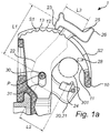
Figs. 1a and1b show a locking device of a bicycle pannier mounting arrangement according to an example embodiment of the present invention; -
Fig. 2a shows a bicycle pannier mounting arrangement according to an example embodiment of the present invention which is provided on a bicycle pannier; -
Fig. 2b shows a bicycle pannier according to an embodiment of the present invention which is provided on a side of a bicycle; -
Figs. 3a-3c show a locking device of a bicycle pannier mounting arrangement according to an example embodiment of the present invention; and -
Figs. 4a-4d show a bicycle pannier mounting arrangement comprising a releasable hook member arrangement according to the third aspect of the present invention. - The drawings show diagrammatic exemplifying embodiments of the present disclosure and are thus not necessarily drawn to scale. It shall be understood that the embodiments shown and described are exemplifying and that the disclosure is not limited to these embodiments. It shall also be noted that some details in the drawings may be exaggerated in order to better describe and illustrate the disclosure. Like reference characters refer to like elements throughout the description, unless expressed otherwise.
-
Figs. 1a and1b show a side view of alocking device 1 of abicycle mounting arrangement 100 for mounting a bicycle pannier 200 (shown infigs. 2a and 2b ) to a bicycle 300 (shown infig. 2b ), according to an embodiment of the present invention. The side view is seen in a direction being parallel to the extension of a pivot axis P of the locking device 1.Thelocking device 1 is configured for locking thebicycle pannier 200 to anelement 301 of thebicycle 300. Theelement 301 is here in the form of a cylindrically shaped bar of a bicycle rack. - The
locking device 1 comprises afirst hook member 10 and asecond hook member 20. Thefirst hook 10 member comprises aninner seat surface 11 which is adapted for enclosing a portion of theelement 301. Thesecond hook member 20 is pivotally connected about the pivot axis P by apivotal connection 30 with respect to thefirst hook member 10 such that thesecond hook member 20 can be pivoted between an open position and a retaining position in a counter-clockwise and clockwise direction, or vice versa. Thepivotal connection 30 may be a pin, such as a pin made of metal, or any other equivalent means. In the open position, theelement 301 can be inserted into and removed out from the locking device, and in the retaining position, thefirst hook member 10 and thesecond hook member 20 are configured to enclose theelement 301 such that it is securely attached to thelocking device 1. An example of the retaining position is shown infig. 1b and an example of an almost open position is shown infig. 1a . - The
second hook member 20 comprises a retaining portion 21 for retaining the elongated element when in the retaining position and alever arm portion 22 which is rigidly connected to the retaining portion 21. As can be seen in this embodiment, the retaining portion 21 and thelever arm portion 22 may together form an L-shaped profile, or modified L-shaped profile, as seen in a sectional plane which is perpendicular to the pivot axis P. An angle between the retaining portion 21 and thelever arm portion 22 may be in the range from 70 to 110 degrees, such as 80-100, or 85-95 degrees, when seen in the sectional plane which is perpendicular to the pivot axis P. In the embodiment shown infigs. 1a-b , the angle therebetween is substantially 90 degrees. - The
lever arm portion 22 extends beyond an outerperipheral surface 12 of thefirst hook member 10, wherein the outerperipheral surface 12 is provided on an opposite side of thefirst hook 10 member with respect to theseat surface 11. Further, thelever arm portion 22 comprises a lockingportion 23 which is configured to pivotally lock thesecond hook member 20 with respect thefirst hook member 10 when in the retaining position. This is accomplished by engaging the lockingportion 23 with cooperating locking means 13 provided on thefirst hook member 10. The locking means 13 are here provided on the outerperipheral surface 12 of the first hook member, which is a preferable embodiment. - Further, the locking means 13 are here provided as a plurality of locking teeth. The locking
portion 23 being provided as a protruding portion, as seen in a sectional plane being perpendicular to the pivot axis P, protruding from thelever arm portion 22 in a direction being substantially opposite to the direction in which the lockingteeth 13 extend. The plurality of lockingteeth 13 are provided along a curvature profile which in this embodiment has a constant radius, as seen in the sectional plane which is perpendicular to the pivot axis P. As further shown, the plurality of lockingteeth 13 may be rounded, as seen in the sectional plane which is perpendicular to the pivot axis P. Thereby, during tightening of thesecond hook member 20 into the retaining position, a sufficient locking force may be provided by a user without the need of using a too high tightening force. - Further, the retaining portion 21 extends from the
pivotal connection 30 to aportion 24 adapted to be in contact with theelement 301 when in the retaining position, whereby a length L1 of thelever arm portion 22 is longer than a length L2 of the retaining portion 21 between thepivotal connection 30 and theportion 24 which is adapted to be in contact with theelement 301 when in the retaining position. Thereby, an improved leverage effect is provided, which in turn will further assure a secure attachment to theelement 301. The lengths L1 and L2 as shown extend in a radial direction from the pivot axis P. - Further, the
pivotal connection 30 as shown in this embodiment is configured to be movable, as seen in a sectional plane being perpendicular to the pivot axis P, such that the lockingportion 23 of thelever arm portion 22 can be moved between an engaged position and a disengaged position with respect to the locking means 13. An example of the disengaged position is shown infig 1a and an example of the engaged position is shown infig 1b . This is accomplished in that thepivotal connection 30 is movable in anaperture 31 provided in thelocking device 1, wherein in this embodiment theaperture 31 is an elongated slot. Further, theaperture 31 is here provided in thefirst hook member 10. As can be seen fromfigs. 1a and1b , thepivotal connection 30 is in the disengaged position provided in an uppermost location of theaperture 31, whereby in the engaged position it is moved further down in theaperture 31. - By configuring the
locking device 1 in this manner, a simplified and efficient release function is provided. More particularly, a user may pull directly or indirectly in thesecond hook member 20 without the need of excessive force such that thepivotal connection 30 is moved in theaperture 31 and thereby such that the lockingteeth 13 are disengaged from the lockingportion 23. This is shown in further detail infigs. 3a-3c . - Further, the locking
portion 23 of thelever arm portion 22 is configured to flex elastically such that it is engaged with the lockingteeth 13 when thesecond hook 10 member is brought to the retaining position. The elasticallyflexible locking portion 23 is integrated with thelever arm portion 22, i.e. the portions are made of one single piece of material. The elastic flexibility is here provided by the configuration of aconnection 25 between thelever arm portion 22 and the lockingportion 23. More particularly, theconnection 25 is provided at a distance L3 from the lockingportion 23, as seen in a sectional plane being perpendicular to the pivot axis P. The distance L3 extends in a tangential direction with respect to the radial extension of thelever arm portion 22 from the pivot axis P. As further shown infigs. 1a and1b , the lockingportion 23 may form part of ahead portion 26 of thesecond hook member 10. Thehead portion 26, which is located outside the outerperipheral surface 12, is preferably configured to be used as a gripping means for a user. Hence, a user may for example by use of hand force tighten thesecond hook member 20 by pushing or pulling in thehead portion 26 in a counter clockwise direction about the pivot axis P, when viewed as shown infigs. 1a and1b . - Further, the
locking device 1 as shown infig. 1b is configured such that a force F1 provided on the retaining portion 21 by theelement 301 when thesecond hook member 20 is in the retaining position is substantially provided in the opposite direction as a corresponding locking force F2 provided to the lockingportion 23 by the lockingteeth 13. By configuring thelocking device 1 in this manner, a reliable locking function will be provided. For example, if an increased force F1 is generated on the retaining portion 21 by theelement 301 caused by e.g. vibrations, the locking force F2 provided to the lockingportion 23 will also increase, but substantially in the opposite direction. By having the two forces substantially aligned, as seen in a sectional plane being perpendicular to the pivot axis P, the risk that the lockingportion 23 will be detached during vibrations can be reduced. In the case the two forces F1 and F2 are not aligned, the risk of accidentally disengaging the locking device may increase. A reason may be that unaligned forces provide force components acting in different directions, whereby one of the force components may act in a direction which may strive to disengage thelocking device 1. - The retaining portion 21 may comprise an
elastic portion 24 adapted for contacting theelement 301 when thesecond hook member 20 is in the retaining position. This has shown to be beneficial for protecting the element from unnecessary damages, scratches etc. Further, theelastic portion 24 has also shown to further improve the locking function. In fact, the force F2 provided on the lockingportion 23 can be further increased since theelastic portion 24 allows the lockingportion 23 to be tightened further when thesecond hook element 20 is provided to the retaining position. - The
second hook member 20 as shown infigs. 1a-1b is pivotable between the retaining position and the open position such that the lockingportion 23 moves along a curvature profile of thefirst hook 10 member which has a first section S1 comprising the lockingteeth 13 and a second section S2 which is free from the locking teeth, whereby the first section S1 is having a larger radius than a radius of the second section S2, when seen in a sectional plane being perpendicular to the pivot axis P. The curvature profile is here provided on the outerperipheral surface 12 of thefirst hook member 10 and forms a convexly shaped outerperipheral surface 12. By this configuration it will be easier for a user to move thesecond hook member 20 between the open position and the retaining position, and vice versa. More particularly, when the lockingportion 23 is located within the first section S1 and when thepivotal connection 30 is located in the uppermost location in theaperture 31, a radial distance between the lockingportion 23 and the first section S1 will be smaller than what a radial distance would be between the lockingportion 23 and the second section S2 when the locking portion is located within the second section S2 and when thepivotal connection 30 is located in the uppermost location in theaperture 31. - Further, the
seat surface 11 is substantially parabola shaped, when seen in a sectional plane being perpendicular to the pivot axis P. By forming the seat surface in this manner, thelocking device 1 may more easily be locked toelements 301 of different sizes, i.e.elements 301 of different cross-sectional sizes. - In
fig. 2a , a perspective view of abicycle pannier 200 comprising a bicyclepannier mounting arrangement 100 according to an example embodiment of the present invention is shown. Thebicycle pannier 200 extends in a width direction w, a height direction h and a depth direction d, which defines a three-dimensional space for accommodating a load. The three directions are perpendicular with respect to each other, whereby the direction w corresponds to an x-direction, the direction d to a y-direction and the direction h to a z-direction of a Cartesian coordinate system. Thebicycle pannier 200 may for example comprise one or more straps (not shown), or the like, which a user can use for carrying thebicycle pannier 200 when it is released from the bicycle. The bicyclepannier mounting arrangement 100 comprises twolocking devices 1 and 1' which are offset in the pannier's width direction w, which in turn is aligned with the pivot axis P. Thelocking devices 1 and 1' are both configured as thelocking device 1 as shown infigs. 1a and1b . Further, thelocking devices 1 and 1' are configured to be moved between respective different positions in the pannier's width direction w, thereby providing a more flexible mounting arrangement which can be adapted for different types of bicycles. The twolocking devices 1 and 1' are preferably connected to and movable along apannier attachment element 50 which is attached to thepannier 200. Thepannier attachment element 50 may be in the form of a rail which comprises a plurality of locking positions for locking thelocking devices 1 and 1' such that they are prevented from being moved in the width direction w when locked thereto. - In
fig. 2a it can be further seen that thesecond hook member 20 and thefirst hook member 10 are configured such that thesecond hook member 20 can be moved between the retaining position and the open position in anopening 27 of thefirst hook member 10. More particularly, the outerperipheral surface 12 is here formed by twotracks tracks tracks - The
bicycle pannier 200 as shown infig 2a further comprises athird hook member 40 according to the third aspect of the invention. Thethird hook member 40 is offset from thelocking devices 1 and 1' in the pannier's height direction h. -
Fig. 2b shows thebicycle pannier 200 as shown infig. 2a when it is mounted onto abicycle 300 by thebicycle mounting arrangement 100. -
Figs. 3a-3c show a locking device of a bicycle pannier mounting arrangement according to an example embodiment of the present invention. Thelocking device 1 as shown is similar in configuration as thelocking device 1 shown in e.g.figs 1a and1b , unless explicitly expressed otherwise. Thesecond hook member 20 is provided in a retaining position infig 3a , in an almost open position infig 3b and in a fully open position infig 3c . - The bicycle pannier mounting arrangement as shown further comprises a releasing
member 60 connected to thesecond hook member 20 and adapted for releasing thesecond hook member 20 from its retaining position, whereby pulling in the releasingmember 60 moves thepivotal connection 30 in theaperture 31 towards the uppermost location such that the lockingportion 23 is released to its disengaged position. - The releasing
member 60 is here a flexible member in the form of a strap. Thestrap 60 is preferably inter-connected to thelocking devices 1 and 1' as shown infig. 2a . Thereby both lockingdevices 1 and 1' can be released at once and also a gripping section (not shown) can be easily provided between the twolocking devices 1 and 1'. - As can be further seen in especially
fig 3c , thelocking device 1 is configured such that theelement 301 will come in contact with thelever arm portion 22 before theelement 301 contacts theseat surface 11 when thesecond hook member 20 is in the open position. This is in this embodiment accomplished in that thesecond hook member 20 can be pivoted a distance such that thelever arm portion 22 will overlap an area where theelement 301 is intended to be provided when it is locked to thelocking device 1, as seen in a sectional plane being perpendicular to the pivot axis P. By configuring thelocking device 1 like this, abicycle pannier 200 may be partially retained or partially locked to thebicycle 300 even before a user has tightened thesecond hook member 2 by pushing or pulling in e.g. thehead portion 26. This can be accomplished by use of gravitational forces exerted on thebicycle pannier 200 when it is provided onto thebicycle 300. An example of the partial locking position is the position of thesecond hook member 20 as shown infig. 3b , i.e. the almost open position. In this position, the retaining portion 21 may have moved a distance about the pivot axis P such that it may hinder thepannier 200 from being released from theelement 301 if an upwardly directed force would be exerted on thepannier 200, i.e. a force which is directed in an opposite direction with respect to the gravitational force. - The embodiments as shown in
figs. 3a-3c and infigs 1a and1b further comprises a protrudingelement 28 which protrudes in a direction which is parallel to the pivot axis P. The protruding element(s) 28, which may be provided on one of, or both of, thetracks first hook member 10 is/are configured for hindering thesecond hook member 20 from being moved from the open position to the retaining position without providing a force onto thesecond hook member 20 with a predetermined force level. Thereby, thesecond hook member 20 may be kept in its open position when thebicycle pannier 200 is released from thebicycle 300. -
Figs. 4a-4d show a bicycle pannier mounting arrangement comprising a releasablehook member arrangement 400 according to the third aspect of the present invention. - The releasable
hook member arrangement 400 comprises: - an
elongated element 410 extending in a longitudinal direction L. Theelongated element 410 is in this embodiment cylindrically formed and is having threads 411 on an envelope surface 412 thereof. Thehook member arrangement 400 further comprises ahook member 40 comprising ahook portion 41 and aconnection portion 42. Theconnection portion 42 of this embodiment comprises abore 43 for connecting thehook member 40 to theelongated element 410. Thehook portion 41 is adapted to extend substantially in a direction being perpendicular to the longitudinal direction L when thehook member 40 is connected to the elongated element. The longitudinal direction L does here correspond to the depth direction d of the pannier as shown in e.g.fig 2a . - The
hook member arrangement 400 further comprises at least onedistance element 420 comprising abore 421 for connecting the at least onedistance element 420 to theelongated element 410, and a lockingmember 430 for locking thehook member 40 and the at least onedistance element 430 to theelongated element 410. The lockingmember 430 is here a nut member and the locking is provided by engaging the threads 411 of the elongated element by corresponding threads (not shown) provided on the lockingmember 430. Thehook member 40 is configured such that thehook portion 41 and theconnection portion 42 are offset, as seen in the longitudinal direction L, when thehook member 40 is connected to theelongated element 410. Thereby, a distance L4 in the longitudinal direction L between thehook portion 41 and aback surface 201 of thebicycle pannier 200 can be varied by releasing thehook member 40, turning it around and mounting it in an opposite mounting direction, see e.g. the different mounting configurations infig. 4b and 4d . Further, the distance L4 may also be varied by positioning thehook member 40 and the at least onedistance element 420 in different order on theelongated element 410, seefig 4c . - The releasable
hook member arrangement 400 may be combined with any other type of bicycle pannier mounting arrangement, but preferably with the bicyclepannier mounting arrangement 100 as disclosed herein. By being able to vary he distance L4, the pannier's 200 attachment to thebicycle 300 may be improved by avoiding unnecessary pivoting about theelement 301 when in use. - The
elongated element 410 further comprises a T-shapedend 413 which is adapted to be movable in a correspondingly formedtrack 414, seefig. 2a , such that theelongated element 410 can be movable in the direction being substantially perpendicular to the longitudinal direction L. Infig. 2a it can be seen that theelongated element 410, and hence also thehook member 40 can be moved in a direction which is parallel to the width direction w of thebicycle pannier 200. - The releasable
hook member arrangement 400 of this embodiment further comprises anadditional distance element 430 configured to be provided in-between thehook member 40 and thebicycle pannier 200. Further, theconnection portion 42, thedistance element 420 and theadditional distance element 430 may comprise means for hindering rotational movement when thehook member 40 is connected to theelongated element 410. - It is to be understood that the present invention is not limited to the embodiments described above and illustrated in the drawings; rather, the skilled person will recognize that many changes and modifications may be made within the scope of the appended claims.
Claims (15)
- A bicycle pannier mounting arrangement (100) for mounting a bicycle pannier (200) to a bicycle (300), comprising:- a locking device (1) for locking the bicycle pannier to an element (301) of the bicycle, wherein the locking device comprises:- a first hook member (10) comprising an inner seat surface (11) being adapted for enclosing a portion of the element,- a second hook member (20),wherein the second hook member is pivotally connected about a pivot axis (P) by a pivotal connection (30) with respect to the first hook member such that the second hook member can be pivoted between an open position and a retaining position, whereby in the open position the element can be inserted into and removed out from the locking device, and whereby in the retaining position the first hook member and the second hook member are configured to enclose the element such that it is securely attached to the locking device, characterized in that,
the second hook member comprises a retaining portion (21) for retaining the elongated element when in the retaining position and a lever arm portion (22) rigidly connected to the retaining portion, the lever arm portion extending beyond an outer peripheral surface (12) of the first hook member, wherein the outer peripheral surface is provided on an opposite side of the first hook member with respect to the seat surface, and wherein the lever arm portion comprises a locking portion (23) which is configured to pivotally lock the second hook member with respect the first hook member when in the retaining position by engaging the locking portion with cooperating locking means (13) provided on the first hook member, which locking means are preferably provided on the outer peripheral surface of the first hook member. - The bicycle pannier mounting arrangement according to claim 1, wherein the retaining portion extends at least partly from the pivotal connection to a portion adapted to be in contact with the element when in the retaining position, and a length of the lever arm portion is longer than a length of the retaining portion between the pivotal connection and the portion which is adapted to be in contact with the element when in the retaining position.
- The bicycle pannier mounting arrangement according to any one of the preceding claims, wherein the pivotal connection is configured to be movable, as seen in a sectional plane being perpendicular to the pivot axis, such that the locking portion of the lever arm portion can be moved between an engaged position and a disengaged position with respect to the locking means.
- The bicycle pannier mounting arrangement according to claim 3, wherein the pivotal connection is movable in an aperture (31) provided in the locking device, preferably the aperture is an elongated slot.
- The bicycle pannier mounting arrangement according to any one of claims 3 or 4, further comprising a releasing member (60) connected to the second hook member and adapted for releasing the second hook member from its retaining position, whereby pulling in the releasing member moves the pivotal connection, preferably in the aperture, such that the locking portion is released to its disengaged position.
- The bicycle pannier mounting arrangement according to any one of the preceding claims, wherein the locking portion of the lever arm portion is configured to flex elastically such that it is engaged with the locking means when the second hook member is in the retaining position.
- The bicycle pannier mounting arrangement according to any one of the preceding claims, wherein the locking device is configured such that a force provided on the retaining portion by the element of the bicycle when the second hook member is in the retaining position is substantially provided in the opposite direction to a corresponding locking force provided to the locking portion by the locking means.
- The bicycle pannier mounting arrangement according to any one of the preceding claims, wherein the retaining portion comprises an elastic portion (24) adapted for contacting the element when the second hook member is in the retaining position.
- The bicycle pannier mounting arrangement according to any one of the preceding claims, wherein the locking means of the first hook member comprises a plurality of locking teeth.
- The bicycle pannier mounting arrangement according to claim 9,
wherein the plurality of locking teeth are rounded, as seen in a sectional plane being perpendicular to the pivot axis. - The bicycle pannier mounting arrangement according to any one of the preceding claims, wherein the second hook member is pivotable between the retaining position and the open position such that the locking portion moves along a curvature profile of the first hook member having a first section (S1) comprising the locking means and a second section (S2) which is free from the locking means, whereby the first section is having a larger radius than a radius of the second section, when seen in a sectional plane being perpendicular to the pivot axis, wherein preferably the curvature profile is provided on the outer peripheral surface of the first hook member.
- The bicycle pannier mounting arrangement according to any one of the preceding claims, wherein the seat surface is substantially parabola shaped, when seen in a sectional plane being perpendicular to the pivot axis.
- The bicycle pannier mounting arrangement according to any one of the preceding claims, comprising two or more locking devices according to any one of the preceding claims which are offset with respect to each other in a direction parallel to the pivot axis.
- The bicycle pannier mounting arrangement according to any one of the preceding claims, further comprising a third hook member (40) for locking the bicycle pannier to another portion of the bicycle, the third hook member being offset from the locking device, when seen in a sectional plane being perpendicular to the pivot axis.
- A bicycle pannier (200) comprising the bicycle pannier mounting arrangement according to any one of the preceding claims.
Priority Applications (5)
| Application Number | Priority Date | Filing Date | Title |
|---|---|---|---|
| EP19175748.3A EP3741655B1 (en) | 2019-05-21 | 2019-05-21 | A bicycle pannier mounting arrangement |
| EP23182498.8A EP4273032A3 (en) | 2019-05-21 | 2019-05-21 | A bicycle pannier mounting arrangement |
| CA3078030A CA3078030A1 (en) | 2019-05-21 | 2020-04-15 | A bicycle pannier mounting arrangement |
| US16/868,283 US11933338B2 (en) | 2019-05-21 | 2020-05-06 | Bicycle pannier mounting arrangement |
| CN202020862261.5U CN213262740U (en) | 2019-05-21 | 2020-05-21 | Bicycle pannier mounting assembly and bicycle pannier |
Applications Claiming Priority (1)
| Application Number | Priority Date | Filing Date | Title |
|---|---|---|---|
| EP19175748.3A EP3741655B1 (en) | 2019-05-21 | 2019-05-21 | A bicycle pannier mounting arrangement |
Related Child Applications (1)
| Application Number | Title | Priority Date | Filing Date |
|---|---|---|---|
| EP23182498.8A Division EP4273032A3 (en) | 2019-05-21 | 2019-05-21 | A bicycle pannier mounting arrangement |
Publications (2)
| Publication Number | Publication Date |
|---|---|
| EP3741655A1 true EP3741655A1 (en) | 2020-11-25 |
| EP3741655B1 EP3741655B1 (en) | 2023-07-05 |
Family
ID=66630142
Family Applications (2)
| Application Number | Title | Priority Date | Filing Date |
|---|---|---|---|
| EP23182498.8A Pending EP4273032A3 (en) | 2019-05-21 | 2019-05-21 | A bicycle pannier mounting arrangement |
| EP19175748.3A Active EP3741655B1 (en) | 2019-05-21 | 2019-05-21 | A bicycle pannier mounting arrangement |
Family Applications Before (1)
| Application Number | Title | Priority Date | Filing Date |
|---|---|---|---|
| EP23182498.8A Pending EP4273032A3 (en) | 2019-05-21 | 2019-05-21 | A bicycle pannier mounting arrangement |
Country Status (4)
| Country | Link |
|---|---|
| US (1) | US11933338B2 (en) |
| EP (2) | EP4273032A3 (en) |
| CN (1) | CN213262740U (en) |
| CA (1) | CA3078030A1 (en) |
Cited By (1)
| Publication number | Priority date | Publication date | Assignee | Title |
|---|---|---|---|---|
| NL2027848B1 (en) * | 2021-03-26 | 2022-10-10 | Van Megen Sports Group B V | Bicycle bag fastening device |
Families Citing this family (3)
| Publication number | Priority date | Publication date | Assignee | Title |
|---|---|---|---|---|
| CN114401866A (en) * | 2019-07-22 | 2022-04-26 | 庞巴迪动力产品公司 | Attachment system for attaching a storage container to a vehicle |
| TWI715422B (en) * | 2020-01-20 | 2021-01-01 | 極點股份有限公司 | Quick release buckle device for bicycle saddle bag |
| CN113998036B (en) * | 2021-12-03 | 2023-03-17 | 东莞顺传五金制品有限公司 | Side bag fastener |
Citations (4)
| Publication number | Priority date | Publication date | Assignee | Title |
|---|---|---|---|---|
| US5884372A (en) * | 1997-08-04 | 1999-03-23 | National Molding Corporation | Refreshment tube retaining device |
| US20100108729A1 (en) | 2008-11-04 | 2010-05-06 | Erica Marie Golub | Bicycle Pannier Mounting System |
| WO2016071092A1 (en) * | 2014-11-06 | 2016-05-12 | MAQUET GmbH | Gripping claw for mounting on a slide rail of an operating table |
| US20180266148A1 (en) * | 2017-03-14 | 2018-09-20 | Harley-Davidson Motor Company Group, LLC | Detachable accessory and latch for same |
Family Cites Families (8)
| Publication number | Priority date | Publication date | Assignee | Title |
|---|---|---|---|---|
| DE9207982U1 (en) * | 1992-06-13 | 1992-09-03 | Wild, Albrecht G., 7997 Immenstaad, De | |
| JPH0853085A (en) * | 1994-06-09 | 1996-02-27 | Honda Access Corp | Container installation device for motorcycle |
| DE29612256U1 (en) * | 1996-07-15 | 1996-10-24 | Vaude Sport Albrecht Von Dewit | Pannier hook |
| US8028877B2 (en) * | 2008-07-11 | 2011-10-04 | Chien Ping Lien | Connection device for connecting bag to side of bicycle carriage rack |
| TWM362159U (en) * | 2009-03-16 | 2009-08-01 | Guo-Ping He | Clamp assembly structure for bicycle side bag |
| DE202010004308U1 (en) * | 2010-03-26 | 2010-07-01 | Ortlieb Sportartikel Gmbh | Holding device for attaching containers to a carrier |
| DE202010004272U1 (en) * | 2010-03-27 | 2010-07-29 | Fabra Vertriebsgesellschaft Mbh | Attachment system for fixing a side pocket to a luggage carrier |
| US9694867B2 (en) * | 2013-03-14 | 2017-07-04 | Bell Sports, Inc. | Locking rack system for bicycles |
-
2019
- 2019-05-21 EP EP23182498.8A patent/EP4273032A3/en active Pending
- 2019-05-21 EP EP19175748.3A patent/EP3741655B1/en active Active
-
2020
- 2020-04-15 CA CA3078030A patent/CA3078030A1/en active Pending
- 2020-05-06 US US16/868,283 patent/US11933338B2/en active Active
- 2020-05-21 CN CN202020862261.5U patent/CN213262740U/en active Active
Patent Citations (4)
| Publication number | Priority date | Publication date | Assignee | Title |
|---|---|---|---|---|
| US5884372A (en) * | 1997-08-04 | 1999-03-23 | National Molding Corporation | Refreshment tube retaining device |
| US20100108729A1 (en) | 2008-11-04 | 2010-05-06 | Erica Marie Golub | Bicycle Pannier Mounting System |
| WO2016071092A1 (en) * | 2014-11-06 | 2016-05-12 | MAQUET GmbH | Gripping claw for mounting on a slide rail of an operating table |
| US20180266148A1 (en) * | 2017-03-14 | 2018-09-20 | Harley-Davidson Motor Company Group, LLC | Detachable accessory and latch for same |
Cited By (1)
| Publication number | Priority date | Publication date | Assignee | Title |
|---|---|---|---|---|
| NL2027848B1 (en) * | 2021-03-26 | 2022-10-10 | Van Megen Sports Group B V | Bicycle bag fastening device |
Also Published As
| Publication number | Publication date |
|---|---|
| EP3741655B1 (en) | 2023-07-05 |
| EP4273032A2 (en) | 2023-11-08 |
| EP4273032A3 (en) | 2024-02-21 |
| US11933338B2 (en) | 2024-03-19 |
| CN213262740U (en) | 2021-05-25 |
| US20200370576A1 (en) | 2020-11-26 |
| CA3078030A1 (en) | 2020-11-21 |
Similar Documents
| Publication | Publication Date | Title |
|---|---|---|
| EP3741655B1 (en) | A bicycle pannier mounting arrangement | |
| US8973992B2 (en) | Child safety seat | |
| CN106256672B (en) | Retainer | |
| US20180006278A1 (en) | Battery holder, battery unit, and battery component including battery holder and battery unit | |
| US6543096B2 (en) | Load carrier system | |
| US20100200715A1 (en) | Quick-release adjustable mounting bracket | |
| EP3619100B1 (en) | Mounting system for a bicycle luggage carrier | |
| US9254778B2 (en) | Adjustable cam buckle | |
| CA3023351C (en) | Conduit clamp | |
| US4850562A (en) | Hanger-retaining clamp for garment bags | |
| JP6210675B2 (en) | Tape measure holder | |
| US11849814B2 (en) | Cam buckle | |
| BR102013004106A2 (en) | Saddle Type Vehicle | |
| FR3083189A1 (en) | DEVICE FOR REMOVABLE MOUNTING OF AN AIR BAG MODULE | |
| US6285160B1 (en) | Retaining device of battery set of scooter | |
| US5588184A (en) | Belt buckle | |
| US4062065A (en) | Safety shoulder strap holder | |
| EP2978635B1 (en) | Device for fastening a load strap | |
| CN110654295A (en) | Hook for fastening a load on the deck of a transport vehicle | |
| KR200487714Y1 (en) | Folding apparatus for bicycle | |
| CN216070334U (en) | Folding mechanism and folding vehicle | |
| US7976086B2 (en) | Safety locking device for a lifting hook | |
| BR112020012451A2 (en) | cargo conveyor shoe | |
| US6631927B1 (en) | Ski pole handle | |
| WO2013173522A1 (en) | Strap for securing cargo on a vehicle |
Legal Events
| Date | Code | Title | Description |
|---|---|---|---|
| PUAI | Public reference made under article 153(3) epc to a published international application that has entered the european phase |
Free format text: ORIGINAL CODE: 0009012 |
|
| STAA | Information on the status of an ep patent application or granted ep patent |
Free format text: STATUS: THE APPLICATION HAS BEEN PUBLISHED |
|
| AK | Designated contracting states |
Kind code of ref document: A1 Designated state(s): AL AT BE BG CH CY CZ DE DK EE ES FI FR GB GR HR HU IE IS IT LI LT LU LV MC MK MT NL NO PL PT RO RS SE SI SK SM TR |
|
| AX | Request for extension of the european patent |
Extension state: BA ME |
|
| STAA | Information on the status of an ep patent application or granted ep patent |
Free format text: STATUS: REQUEST FOR EXAMINATION WAS MADE |
|
| 17P | Request for examination filed |
Effective date: 20201218 |
|
| RBV | Designated contracting states (corrected) |
Designated state(s): AL AT BE BG CH CY CZ DE DK EE ES FI FR GB GR HR HU IE IS IT LI LT LU LV MC MK MT NL NO PL PT RO RS SE SI SK SM TR |
|
| STAA | Information on the status of an ep patent application or granted ep patent |
Free format text: STATUS: EXAMINATION IS IN PROGRESS |
|
| 17Q | First examination report despatched |
Effective date: 20210609 |
|
| GRAP | Despatch of communication of intention to grant a patent |
Free format text: ORIGINAL CODE: EPIDOSNIGR1 |
|
| STAA | Information on the status of an ep patent application or granted ep patent |
Free format text: STATUS: GRANT OF PATENT IS INTENDED |
|
| INTG | Intention to grant announced |
Effective date: 20230320 |
|
| GRAS | Grant fee paid |
Free format text: ORIGINAL CODE: EPIDOSNIGR3 |
|
| GRAA | (expected) grant |
Free format text: ORIGINAL CODE: 0009210 |
|
| STAA | Information on the status of an ep patent application or granted ep patent |
Free format text: STATUS: THE PATENT HAS BEEN GRANTED |
|
| AK | Designated contracting states |
Kind code of ref document: B1 Designated state(s): AL AT BE BG CH CY CZ DE DK EE ES FI FR GB GR HR HU IE IS IT LI LT LU LV MC MK MT NL NO PL PT RO RS SE SI SK SM TR |
|
| P01 | Opt-out of the competence of the unified patent court (upc) registered |
Effective date: 20230528 |
|
| REG | Reference to a national code |
Ref country code: CH Ref legal event code: EP |
|
| REG | Reference to a national code |
Ref country code: AT Ref legal event code: REF Ref document number: 1584611 Country of ref document: AT Kind code of ref document: T Effective date: 20230715 |
|
| REG | Reference to a national code |
Ref country code: DE Ref legal event code: R096 Ref document number: 602019031996 Country of ref document: DE |
|
| REG | Reference to a national code |
Ref country code: IE Ref legal event code: FG4D |
|
| REG | Reference to a national code |
Ref country code: NL Ref legal event code: FP |
|
| REG | Reference to a national code |
Ref country code: SE Ref legal event code: TRGR |
|
| REG | Reference to a national code |
Ref country code: LT Ref legal event code: MG9D |
|
| REG | Reference to a national code |
Ref country code: AT Ref legal event code: MK05 Ref document number: 1584611 Country of ref document: AT Kind code of ref document: T Effective date: 20230705 |
|
| PG25 | Lapsed in a contracting state [announced via postgrant information from national office to epo] |
Ref country code: GR Free format text: LAPSE BECAUSE OF FAILURE TO SUBMIT A TRANSLATION OF THE DESCRIPTION OR TO PAY THE FEE WITHIN THE PRESCRIBED TIME-LIMIT Effective date: 20231006 |
|
| PG25 | Lapsed in a contracting state [announced via postgrant information from national office to epo] |
Ref country code: ES Free format text: LAPSE BECAUSE OF FAILURE TO SUBMIT A TRANSLATION OF THE DESCRIPTION OR TO PAY THE FEE WITHIN THE PRESCRIBED TIME-LIMIT Effective date: 20230705 |
|
| PG25 | Lapsed in a contracting state [announced via postgrant information from national office to epo] |
Ref country code: IS Free format text: LAPSE BECAUSE OF FAILURE TO SUBMIT A TRANSLATION OF THE DESCRIPTION OR TO PAY THE FEE WITHIN THE PRESCRIBED TIME-LIMIT Effective date: 20231105 |
|
| PG25 | Lapsed in a contracting state [announced via postgrant information from national office to epo] |
Ref country code: RS Free format text: LAPSE BECAUSE OF FAILURE TO SUBMIT A TRANSLATION OF THE DESCRIPTION OR TO PAY THE FEE WITHIN THE PRESCRIBED TIME-LIMIT Effective date: 20230705 Ref country code: PT Free format text: LAPSE BECAUSE OF FAILURE TO SUBMIT A TRANSLATION OF THE DESCRIPTION OR TO PAY THE FEE WITHIN THE PRESCRIBED TIME-LIMIT Effective date: 20231106 Ref country code: NO Free format text: LAPSE BECAUSE OF FAILURE TO SUBMIT A TRANSLATION OF THE DESCRIPTION OR TO PAY THE FEE WITHIN THE PRESCRIBED TIME-LIMIT Effective date: 20231005 Ref country code: LV Free format text: LAPSE BECAUSE OF FAILURE TO SUBMIT A TRANSLATION OF THE DESCRIPTION OR TO PAY THE FEE WITHIN THE PRESCRIBED TIME-LIMIT Effective date: 20230705 Ref country code: LT Free format text: LAPSE BECAUSE OF FAILURE TO SUBMIT A TRANSLATION OF THE DESCRIPTION OR TO PAY THE FEE WITHIN THE PRESCRIBED TIME-LIMIT Effective date: 20230705 Ref country code: IS Free format text: LAPSE BECAUSE OF FAILURE TO SUBMIT A TRANSLATION OF THE DESCRIPTION OR TO PAY THE FEE WITHIN THE PRESCRIBED TIME-LIMIT Effective date: 20231105 Ref country code: HR Free format text: LAPSE BECAUSE OF FAILURE TO SUBMIT A TRANSLATION OF THE DESCRIPTION OR TO PAY THE FEE WITHIN THE PRESCRIBED TIME-LIMIT Effective date: 20230705 Ref country code: GR Free format text: LAPSE BECAUSE OF FAILURE TO SUBMIT A TRANSLATION OF THE DESCRIPTION OR TO PAY THE FEE WITHIN THE PRESCRIBED TIME-LIMIT Effective date: 20231006 Ref country code: FI Free format text: LAPSE BECAUSE OF FAILURE TO SUBMIT A TRANSLATION OF THE DESCRIPTION OR TO PAY THE FEE WITHIN THE PRESCRIBED TIME-LIMIT Effective date: 20230705 Ref country code: ES Free format text: LAPSE BECAUSE OF FAILURE TO SUBMIT A TRANSLATION OF THE DESCRIPTION OR TO PAY THE FEE WITHIN THE PRESCRIBED TIME-LIMIT Effective date: 20230705 Ref country code: AT Free format text: LAPSE BECAUSE OF FAILURE TO SUBMIT A TRANSLATION OF THE DESCRIPTION OR TO PAY THE FEE WITHIN THE PRESCRIBED TIME-LIMIT Effective date: 20230705 |
|
| PG25 | Lapsed in a contracting state [announced via postgrant information from national office to epo] |
Ref country code: PL Free format text: LAPSE BECAUSE OF FAILURE TO SUBMIT A TRANSLATION OF THE DESCRIPTION OR TO PAY THE FEE WITHIN THE PRESCRIBED TIME-LIMIT Effective date: 20230705 |
|
| PG25 | Lapsed in a contracting state [announced via postgrant information from national office to epo] |
Ref country code: SM Free format text: LAPSE BECAUSE OF FAILURE TO SUBMIT A TRANSLATION OF THE DESCRIPTION OR TO PAY THE FEE WITHIN THE PRESCRIBED TIME-LIMIT Effective date: 20230705 Ref country code: RO Free format text: LAPSE BECAUSE OF FAILURE TO SUBMIT A TRANSLATION OF THE DESCRIPTION OR TO PAY THE FEE WITHIN THE PRESCRIBED TIME-LIMIT Effective date: 20230705 Ref country code: EE Free format text: LAPSE BECAUSE OF FAILURE TO SUBMIT A TRANSLATION OF THE DESCRIPTION OR TO PAY THE FEE WITHIN THE PRESCRIBED TIME-LIMIT Effective date: 20230705 Ref country code: DK Free format text: LAPSE BECAUSE OF FAILURE TO SUBMIT A TRANSLATION OF THE DESCRIPTION OR TO PAY THE FEE WITHIN THE PRESCRIBED TIME-LIMIT Effective date: 20230705 Ref country code: CZ Free format text: LAPSE BECAUSE OF FAILURE TO SUBMIT A TRANSLATION OF THE DESCRIPTION OR TO PAY THE FEE WITHIN THE PRESCRIBED TIME-LIMIT Effective date: 20230705 Ref country code: SK Free format text: LAPSE BECAUSE OF FAILURE TO SUBMIT A TRANSLATION OF THE DESCRIPTION OR TO PAY THE FEE WITHIN THE PRESCRIBED TIME-LIMIT Effective date: 20230705 |