EP3741605A1 - Temperature controlled goods vehicles - Google Patents
Temperature controlled goods vehicles Download PDFInfo
- Publication number
- EP3741605A1 EP3741605A1 EP19382419.0A EP19382419A EP3741605A1 EP 3741605 A1 EP3741605 A1 EP 3741605A1 EP 19382419 A EP19382419 A EP 19382419A EP 3741605 A1 EP3741605 A1 EP 3741605A1
- Authority
- EP
- European Patent Office
- Prior art keywords
- threshold value
- average current
- value
- battery
- amps
- Prior art date
- Legal status (The legal status is an assumption and is not a legal conclusion. Google has not performed a legal analysis and makes no representation as to the accuracy of the status listed.)
- Granted
Links
Images


Classifications
-
- B—PERFORMING OPERATIONS; TRANSPORTING
- B60—VEHICLES IN GENERAL
- B60L—PROPULSION OF ELECTRICALLY-PROPELLED VEHICLES; SUPPLYING ELECTRIC POWER FOR AUXILIARY EQUIPMENT OF ELECTRICALLY-PROPELLED VEHICLES; ELECTRODYNAMIC BRAKE SYSTEMS FOR VEHICLES IN GENERAL; MAGNETIC SUSPENSION OR LEVITATION FOR VEHICLES; MONITORING OPERATING VARIABLES OF ELECTRICALLY-PROPELLED VEHICLES; ELECTRIC SAFETY DEVICES FOR ELECTRICALLY-PROPELLED VEHICLES
- B60L1/00—Supplying electric power to auxiliary equipment of vehicles
-
- B—PERFORMING OPERATIONS; TRANSPORTING
- B60—VEHICLES IN GENERAL
- B60H—ARRANGEMENTS OF HEATING, COOLING, VENTILATING OR OTHER AIR-TREATING DEVICES SPECIALLY ADAPTED FOR PASSENGER OR GOODS SPACES OF VEHICLES
- B60H1/00—Heating, cooling or ventilating devices
- B60H1/32—Cooling devices
- B60H1/3204—Cooling devices using compression
- B60H1/3205—Control means therefor
- B60H1/3211—Control means therefor for increasing the efficiency of a vehicle refrigeration cycle
-
- B—PERFORMING OPERATIONS; TRANSPORTING
- B60—VEHICLES IN GENERAL
- B60H—ARRANGEMENTS OF HEATING, COOLING, VENTILATING OR OTHER AIR-TREATING DEVICES SPECIALLY ADAPTED FOR PASSENGER OR GOODS SPACES OF VEHICLES
- B60H1/00—Heating, cooling or ventilating devices
- B60H1/32—Cooling devices
- B60H1/3204—Cooling devices using compression
- B60H1/3232—Cooling devices using compression particularly adapted for load transporting vehicles
-
- B—PERFORMING OPERATIONS; TRANSPORTING
- B60—VEHICLES IN GENERAL
- B60H—ARRANGEMENTS OF HEATING, COOLING, VENTILATING OR OTHER AIR-TREATING DEVICES SPECIALLY ADAPTED FOR PASSENGER OR GOODS SPACES OF VEHICLES
- B60H1/00—Heating, cooling or ventilating devices
- B60H1/32—Cooling devices
- B60H1/3204—Cooling devices using compression
- B60H1/3222—Cooling devices using compression characterised by the compressor driving arrangements, e.g. clutches, transmissions or multiple drives
-
- B—PERFORMING OPERATIONS; TRANSPORTING
- B60—VEHICLES IN GENERAL
- B60H—ARRANGEMENTS OF HEATING, COOLING, VENTILATING OR OTHER AIR-TREATING DEVICES SPECIALLY ADAPTED FOR PASSENGER OR GOODS SPACES OF VEHICLES
- B60H1/00—Heating, cooling or ventilating devices
- B60H1/32—Cooling devices
- B60H1/3204—Cooling devices using compression
- B60H1/3226—Self-contained devices, i.e. including own drive motor
-
- B—PERFORMING OPERATIONS; TRANSPORTING
- B60—VEHICLES IN GENERAL
- B60R—VEHICLES, VEHICLE FITTINGS, OR VEHICLE PARTS, NOT OTHERWISE PROVIDED FOR
- B60R16/00—Electric or fluid circuits specially adapted for vehicles and not otherwise provided for; Arrangement of elements of electric or fluid circuits specially adapted for vehicles and not otherwise provided for
- B60R16/02—Electric or fluid circuits specially adapted for vehicles and not otherwise provided for; Arrangement of elements of electric or fluid circuits specially adapted for vehicles and not otherwise provided for electric constitutive elements
- B60R16/03—Electric or fluid circuits specially adapted for vehicles and not otherwise provided for; Arrangement of elements of electric or fluid circuits specially adapted for vehicles and not otherwise provided for electric constitutive elements for supply of electrical power to vehicle subsystems or for
-
- H—ELECTRICITY
- H02—GENERATION; CONVERSION OR DISTRIBUTION OF ELECTRIC POWER
- H02J—ELECTRIC POWER NETWORKS; CIRCUIT ARRANGEMENTS OR SYSTEMS FOR SUPPLYING OR DISTRIBUTING ELECTRIC POWER; SYSTEMS FOR STORING ELECTRIC ENERGY
- H02J7/00—Circuit arrangements for charging or discharging batteries or for supplying loads from batteries
- H02J7/14—Circuit arrangements for charging or discharging batteries or for supplying loads from batteries for charging batteries from dynamo-electric generators driven at varying speed, e.g. on vehicle
- H02J7/1423—Circuit arrangements for charging or discharging batteries or for supplying loads from batteries for charging batteries from dynamo-electric generators driven at varying speed, e.g. on vehicle with multiple batteries
-
- H—ELECTRICITY
- H02—GENERATION; CONVERSION OR DISTRIBUTION OF ELECTRIC POWER
- H02J—ELECTRIC POWER NETWORKS; CIRCUIT ARRANGEMENTS OR SYSTEMS FOR SUPPLYING OR DISTRIBUTING ELECTRIC POWER; SYSTEMS FOR STORING ELECTRIC ENERGY
- H02J7/00—Circuit arrangements for charging or discharging batteries or for supplying loads from batteries
- H02J7/34—Parallel operation in networks using both storage and other DC sources, e.g. providing buffering
- H02J7/35—Parallel operation in networks using both storage and other DC sources, e.g. providing buffering with light sensitive cells
-
- H—ELECTRICITY
- H02—GENERATION; CONVERSION OR DISTRIBUTION OF ELECTRIC POWER
- H02J—ELECTRIC POWER NETWORKS; CIRCUIT ARRANGEMENTS OR SYSTEMS FOR SUPPLYING OR DISTRIBUTING ELECTRIC POWER; SYSTEMS FOR STORING ELECTRIC ENERGY
- H02J7/00—Circuit arrangements for charging or discharging batteries or for supplying loads from batteries
- H02J7/80—Circuit arrangements for charging or discharging batteries or for supplying loads from batteries including monitoring or indicating arrangements
-
- H—ELECTRICITY
- H02—GENERATION; CONVERSION OR DISTRIBUTION OF ELECTRIC POWER
- H02J—ELECTRIC POWER NETWORKS; CIRCUIT ARRANGEMENTS OR SYSTEMS FOR SUPPLYING OR DISTRIBUTING ELECTRIC POWER; SYSTEMS FOR STORING ELECTRIC ENERGY
- H02J2207/00—Details of circuit arrangements for charging or discharging batteries or supplying loads from batteries
- H02J2207/40—Details of circuit arrangements for charging or discharging batteries or supplying loads from batteries adapted for charging from various sources, e.g. AC, DC or multivoltage
Definitions
- the present disclosure relates to the field of temperature controlled goods vehicles.
- temperature controlled goods vehicles have been developed for transporting such goods.
- One common form of temperature controlled goods vehicle is a temperature controlled trailer configured to be towed by a tractor unit for transportation of goods by road, though other forms of temperature controlled goods vehicle such as trucks, vans and the like are available.
- Such temperature controlled goods vehicles typically include a temperature control unit that is operative to maintain the temperature within a goods space of the vehicle at a predetermined temperature or within a predetermined temperature range.
- the temperature control unit may be, for example, a refrigeration unit or a heating unit, or a combined refrigeration and heating unit.
- a temperature control unit of this kind typically includes an engine, e.g. a diesel engine, temperature control components such as a pump, heat exchanger and associated pipework, and electrical components such as temperature sensors, a controller, and a display unit.
- the engine is operative to drive the pump and other temperature control components whilst a battery is provided to power the electrical components.
- the temperature control unit typically also includes an alternator which is driven by the engine to provide a charging current to recharge the battery.
- the temperature control unit may be operable in a first mode of operation in which the engine and temperature control components operate continuously, to maintain the temperature in the goods space of the vehicle at a predetermined temperature or within a predetermined relatively narrow temperature range.
- the temperature control unit may also be operable in a second mode of operation in which the engine and temperature control components operate intermittently under the control of the controller, to maintain the temperature in the goods space of the vehicle within a predetermined temperature range that is typically broader than the relatively narrow temperature range of the first mode of operation.
- the amount of fuel e.g. diesel
- the amount of fuel e.g. diesel
- the temperature control unit may be operative to start the engine periodically to recharge the battery even when operation of the engine is not required to achieve a desired temperature within the goods space of the vehicle.
- running the engine solely to charge the battery increases the fuel consumption of the temperature control unit.
- the ever increasing cost of fuel and continued drive to reduce exhaust gas emissions gives rise to a desire to reduce the fuel consumption of such temperature control units.
- the invention provides a method for operating a temperature control system for a temperature controlled goods vehicle, wherein the temperature control system comprises: a solar panel and a temperature control unit comprising: one or more temperature control components; a battery coupled to the solar cell for receiving a first charging current i 1 from the solar cell; an engine operative to supply a second charging current i 2 to the battery; and a controller, the method comprising: at the controller: monitoring a voltage of the battery; if the voltage of the battery exceeds a first battery voltage threshold for a first predetermined amount of time: determining a first energy count value representing an amount of energy delivered by the solar panel in a predetermined time period; if the first energy count value exceeds a first energy count value threshold: determining an average current value representing an average amount of energy delivered by the solar panel in the predetermined time period; and increasing a cycle threshold value that determines when the engine is deactivated so as to stop supplying the second charging current i 2 to the battery based on the average current value.
- Increasing the cycle threshold value may comprise: if the average current value is greater than a first average current threshold value but less than a second average current threshold value and the cycle threshold value is less than a first cycle threshold value, increasing the cycle threshold value to the first cycle threshold value.
- the first average current threshold value may be, for example, 1 amp
- the second average current threshold value may be, for example 1.5 amps
- the first cycle threshold value may be, for example, 5 amps.
- Increasing the cycle threshold value may comprise: if the average current value is greater than a third average current threshold value but less than a fourth average current threshold value, increasing the cycle threshold value to a second cycle threshold value; if the average current value is greater than a fifth average current threshold value but less than a sixth average current threshold value, increasing the cycle threshold value to a third cycle threshold value; if the average current value is greater than a seventh average current threshold value but less than an eighth average current threshold value, increasing the cycle threshold value to a fourth cycle threshold value; and if the average current value is greater than a ninth average current threshold value, increasing the cycle threshold value to a fifth cycle threshold value.
- the third average current threshold value may be, for example, 1.5 amps
- the fourth average current threshold value may be, for example, 2 amps
- the second cycle threshold value may be, for example, 6 amps
- the fifth average current threshold value may be, for example, 2 amps
- the sixth average current threshold value may be, for example, 2.5 amps
- the third cycle threshold value may be, for example, 7 amps
- the seventh average current threshold value may be, for example, 2.5 amps
- the eighth average current threshold value may be, for example, 3 amps
- the fourth cycle threshold value may be, for example, 8 amps
- the fifth cycle threshold value may be, for example, 9 amps.
- the method may further comprise: at the controller: monitoring the voltage of the battery; if the voltage of the battery is below a second battery voltage threshold for a second predetermined amount of time: determining a second energy count value representing an amount of energy delivered by the solar panel in a predetermined time period; if the second energy count value is below a second energy count value threshold: determining an average power value representing an average amount of energy delivered by the solar panel in the predetermined time period; and reducing a cycle threshold value that determines when the engine is deactivated so as to stop supplying the second charging current to the battery based on the determined average power value.
- the invention provides a method for operating a temperature control system for a temperature controlled goods vehicle, wherein the temperature control system comprises: a solar panel; and a temperature control unit comprising: one or more temperature control components; a battery coupled to the solar cell for receiving a first charging current i 1 from the solar cell; an engine operative to supply a second charging current i 2 to the battery; and a controller, the method comprising: at the controller: monitoring a voltage of the battery; if the voltage of the battery is below a second battery voltage threshold for a second predetermined amount of time: determining a second energy count value representing an amount of energy delivered by the solar panel in a predetermined time period; if the second energy count value is below a second energy count value threshold: determining an average current value representing an average amount of energy delivered by the solar panel in the predetermined time period; and reducing a cycle threshold value that determines when the engine is deactivated so as to stop supplying the second charging current i 2 to the battery based on the average current value.
- Reducing the cycle threshold value may comprise: if the average current value is greater than a first average current threshold value and the cycle threshold value is greater than a first cycle threshold value, reducing the cycle threshold value to the first cycle threshold value.
- the first average current threshold value is 2 amps and the first cycle threshold value may be, for example, 5 amps.
- Reducing the cycle threshold value may comprise: if the average current threshold value is greater than a second average current value but less than a third average current threshold value, reducing the cycle threshold value to a second cycle threshold value; if the average current threshold value is greater than a fourth average current value but less than a fifth average current threshold value, reducing the cycle threshold value to a third cycle threshold value; if the average current threshold value is greater than a sixth average current value but less than a seventh average current threshold value, reducing the cycle threshold value to a fourth cycle threshold value.
- the second average current threshold value may be, for example, 1.5 amps
- the third average current threshold value may be, for example, 2 amps
- the second cycle threshold value may be, for example, 4 amps
- the fourth average current threshold value may be, for example, 1 amp
- the fifth average current threshold value may be, for example, 1.5 amps
- the third cycle threshold value may be, for example, 3 amps
- the sixth average current threshold value may be, for example, 0 amps
- the seventh average current threshold value may be, for example, 1 amp
- the fourth cycle threshold value may be, for example, 2 amps.
- the temperature control unit may comprise a refrigeration unit, for example.
- the invention provides a system for a temperature-controlled goods vehicle, the system comprising: a solar panel; a temperature control unit comprising: an engine; one or more temperature control components; a battery; a controller; and a memory, wherein the memory stores instructions which, when executed by the controller cause the controller to perform the method of the first or second aspects.
- the invention provides a computer program comprising instructions which, when executed by a processor, cause the processor to perform the method of the first or second aspects.
- the invention provides a temperature controlled goods vehicle comprising a system according to the third aspect.
- a temperature controlled goods vehicle is shown generally at 100.
- the temperature controlled goods vehicle 100 is a trailer unit configured to be towed by a tractor unit, but it is to be appreciated that the present disclosure is not limited to such trailer units, but may instead be embodied in a wide variety of different temperature controlled goods vehicles including, but not limited to, vans, trucks, trains and the like.
- the temperature controlled goods vehicle 100 includes a photovoltaic solar panel 200 comprising one or more photovoltaic cells and a temperature control unit 300, which may be, for example, a refrigeration system.
- the solar panel 200 is coupled to the temperature control unit 300 to provide a first charging current for a battery of the temperature control unit 300, as will be described in more detail below.
- FIG. 2 is a schematic representation of the temperature control unit 300.
- the temperature control unit 300 may be a refrigeration system.
- the temperature control unit includes a battery 310 which provides electrical power for electrical components such as a controller 320 of the temperature control unit 300 and electrical components 330 such as temperature sensors and actuators which may be provided externally of the temperature control unit 300 and which, in use of the temperature control unit 300, may be disposed within an interior of the temperature controlled goods vehicle 100.
- the temperature control unit 300, solar panel 200 and external electrical components 330 are thus parts of a temperature control system for a temperature controlled good vehicle 100.
- the temperature control unit 300 also includes an engine 340, which may be, for example, a diesel engine.
- the engine 340 provides motive power, where necessary, to temperature control components 350 of the temperature control unit 300 such as pumps, compressors and the like.
- the temperature control unit 300 may include other temperature control components that do not require motive power, such as heat exchangers, pipework and the like. Such components will not be described in detail here as they are not germane to the present disclosure.
- the battery 310 is electrically coupled (directly or indirectly) to the solar panel 200 so as to receive from the solar panel 200 a first charging current i 1 for charging the battery 310 when sufficient solar energy is incident upon the solar panel 200.
- the engine 340 includes an alternator or other electrical generator having an output that is electrically coupled to the battery 310 so as to provide a second charging current i 2 to the battery 310 when the engine 340 is operative.
- the controller 320 may be, for example, a microprocessor, microcontroller, application specific integrated circuit (ASIC), field programmable gate array (FPGA) or the like, and is coupled to a memory 360 (e.g. a flash memory, random access memory (RAM), read-only memory (ROM), electrically erasable and programmable read only memory (EEPROM) or the like) which stores a computer program comprising instructions that are executed by the controller 320.
- a memory 360 e.g. a flash memory, random access memory (RAM), read-only memory (ROM), electrically erasable and programmable read only memory (EEPROM) or the like
- RAM random access memory
- ROM read-only memory
- EEPROM electrically erasable and programmable read only memory
- the controller 320 is configured to monitor signals from the external electrical components 330 such as signals indicative of the temperature within a goods space of the temperature controlled goods vehicle 100 and to control the operation of the engine 340 to maintain the temperature within the goods space at a predefined setpoint temperature, or within a predefined temperature range.
- the controller 320 is also configured to monitor a voltage at the battery 310 and the first charging current i 1 output by the solar panel 200 to the battery 310 and to control the amount of time that the engine 340 is in operation solely to recharge the battery 310, based on these monitored parameters, as will be described in more detail with reference to Figures 3 and 4 .
- existing temperature control units may operable in a first mode of operation in which the engine and temperature control components operate continuously, to maintain the temperature in the goods space of the vehicle at a predetermined temperature or within a predetermined relatively narrow temperature range and in a second mode of operation in which the engine and temperature control components operate intermittently under the control of the controller, to maintain the temperature in the goods space of the vehicle within a predetermined relatively broader temperature range.
- the engine may be used to recharge the battery even when it is not required to maintain the temperature within the desired temperature range.
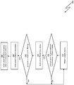
- Figure 3 is a flow diagram illustrating a method 500, performed by the controller 320 in accordance with instructions stored in the memory 360, for managing the amount of time that the engine 340 is in operation solely to recharge the battery 310, based on a dynamic cycle threshold value.
- This dynamic cycle threshold value represents a threshold value to which the second charging current i 2 provided by the generator (e.g. alternator) of the engine 340 must fall in order to trigger the controller 320 to deactivate the engine 340 so as to stop supplying the second charging current i 2 to the battery 310.
- the cycle threshold value is dynamic in the sense that it is variable, based on the amount of energy delivered by the solar panel 200 in a predefined period of time, as will be explained in more detail below.
- the magnitude of the second charging current i 2 supplied by the generator (e.g. alternator) of the engine 340 of the temperature control unit 300 decreases as the level of charge of the battery 310 increases.
- Increasing the cycle threshold value therefore reduces the amount of time for which the engine 340 is used solely to recharge the battery 310, since a higher cycle threshold value will be reached at a lower battery charge level than a lower cycle threshold value.
- Varying the cycle threshold value based on the amount of energy delivered by the solar panel 200 ensures that the first charging current i 1 provided by the solar panel 200 can compensate for the shortfall in the charging current i 2 supplied by the generator of the engine 340 when the engine 340 is deactivated.
- the method 500 can be used to reduce the amount of time for which the engine 340 is used solely to charge the battery 310, thus reducing the fuel consumption of the temperature control unit 300.
- the dynamic cycle value threshold is initially set to a default value which may be, for example, less than 5 amps.
- the controller 320 continuously monitors the voltage at the battery 310 (step 510) and determines if the battery voltage has exceeded a predefined first battery voltage threshold (e.g. approximately 12.6 volts) for a predetermined amount of time (e.g. 2 hours). A positive determination is indicative that the solar panel 200 has been able to supply sufficient first charging current i 1 to maintain the battery 310 at a state of charge that is capable of sustaining normal operation of the temperature control unit 300 without requiring additional charging current from the engine 340.
- a predefined first battery voltage threshold e.g. approximately 12.6 volts
- a predetermined amount of time e.g. 2 hours
- the controller 320 determines, at step 520, that the battery voltage has indeed exceeded the first predefined battery voltage threshold for the predetermined amount of time, it proceeds to step 530, at which the controller 320 determines a first energy count value.
- the energy count value is a metric indicative of the amount of energy delivered by the solar panel 200 in a predetermined period of time, and may be determined, for example, by integrating the value of the first charging current i 1 over the predetermined period of time.
- the controller 320 compares the energy count value to an energy count value threshold (e.g. 2Ah) to determine whether the total amount of energy delivered by the solar panel 200 exceeds a minimum amount of energy required to maintain the battery 310 at a state of charge that is capable of sustaining normal operation of the temperature control unit 300 without requiring additional charging current from the engine 340.
- an energy count value threshold e.g. 2Ah
- step 550 the controller 320 determines an average current value indicative of the average current per unit time delivered by the solar panel 200 over the predetermined amount of time.
- the controller 320 then (at step 550) increases the cycle threshold value based on the determined average current value. For example, if the average current value is greater than 1 amp but less than 1.5 amps and the current cycle threshold value is less than 5 amps, the controller 320 may increase the cycle threshold value to 5 amps. If the average current value is greater than 1.5 amps but less than 2 amps, the controller 320 may increase the cycle threshold value to 6 amps. If the average current value is greater than 2 amps but less than 2.5 amps, the controller 320 may increase the cycle threshold value to 7 amps. If the average current value is greater than 2.5 amps but less than 3 amps, the controller 320 may increase the cycle threshold value to 8 amps. If the average current value is greater than 3 amps, the controller 320 may increase the cycle threshold value to 9 amps.
- the cycle threshold value is adjusted based on the amount of first charging current i 1 supplied by the solar panel 200.
- the first charging current i 1 provided by the solar panel 200 may not be, or may no longer be, sufficient to compensate for the shortfall in the second charging current i 2 supplied by the generator of the engine 340 when the engine 340 is deactivated.
- the cycle threshold value can be reduced, such that the engine 340 will be deactivated at a later point, when the second charging current i 2 is lower, because the charge level of the battery 310 will need to be higher before the reduced amount of first charging current i 1 provided by the solar panel 200 will be sufficient to compensate for the shortfall in charging current i 2 supplied by the generator of the engine 340 when the engine 340 is deactivated.
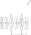
- Figure 4 is a flow diagram illustrating steps in method 600, performed by the controller 320 in accordance with the instructions stored in the memory 360, for increasing the amount of time that the engine 340 is in operation solely to recharge the battery 310, by reducing the dynamic cycle threshold value.
- the steps of the method 600 illustrated in Figure 4 may be performed subsequently to the steps of the method 500 illustrated in Figure 3 (e.g. the method 600 may be an extension of the method 500), for example if conditions change after the dynamic cycle threshold value has been increased in accordance with the method 500, or may be performed separately or in isolation from the steps of the method 500.
- the dynamic cycle value threshold is initially set to a value which may be, for example, a default value or may be a value determined in accordance with the method 500 described above and illustrated in Figure 5.
- the initial value of the dynamic cycle value threshold may be, for example, greater than 5 amps.
- the controller 320 continuously monitors the voltage at the battery 310 (step 610) and determines, at step 620, if the battery voltage has been below a predefined battery voltage threshold (e.g. 12.6 volts) for a predetermined amount of time (e.g. 2 hours). A positive determination is indicative that the solar panel has not been able to supply sufficient first charging current i 1 to maintain the battery 310 at a state of charge that is capable of sustaining normal operation of the temperature control unit 300 without requiring additional charging current from the engine 340.
- a predefined battery voltage threshold e.g. 12.6 volts
- a predetermined amount of time e.g. 2 hours
- the controller 320 determines an energy count value.
- the energy count value is a metric indicative of the amount of energy delivered by the solar panel 200 in a predetermined period of time, and may be determined, for example, by integrating the value of the first charging current i 1 over the predetermined period of time.
- the controller 320 compares the energy count value to an energy count value threshold (e.g. 2Ah) to determine whether the total amount of energy delivered by the solar panel 200 is less than a minimum amount of energy required to maintain the battery 310 at a state of charge that is capable of sustaining normal operation of the temperature control unit 300 without requiring additional charging current from the engine 340.
- an energy count value threshold e.g. 2Ah
- step 650 the controller 320 determines an average current value indicative of the average current per unit time delivered by the solar panel 200 over the predetermined amount of time.
- the controller 320 then (at step 660) reduces the cycle threshold value based on the average current value. For example, if the average current value is greater than 2 amps and the current cycle threshold value is greater than 5 amps, the controller 320 may reduce the cycle threshold value to 5 amps. If the average current value is greater than 1.5 amps but less than 2 amps, the controller 320 may reduce the cycle threshold value to 4 amps. If the average current value is greater than 1 amp but less than 1.5 amps, the controller 320 may reduce the cycle threshold value to 3 amps. If the average current value is greater than 0 amps but less than 1 amp, the controller 320 may reduce the cycle threshold value to 2 amps.
- the cycle threshold value is adjusted based on the amount of charging current i 1 supplied by the solar panel 200.
- the temperature control unit 300 and the methods 500, 600 described above permit the amount of time for which the engine 340 is operational to be adjusted according to the ability of the solar panel 200 to supply charging current to the battery 310.
- the fuel consumption of the temperature control unit 300 can be reduced in conditions in which the solar panel 200 is able to meet the charging current required to maintain the battery 310 in a state of charge that is capable of sustaining normal operation of the temperature control unit 300 without compromising the operation of the temperature control unit 300 in conditions in which the solar panel 200 is not able to meet these charging current requirements.
- the memory 360 will typically be programmed at the time of manufacture of the temperature control unit 300 with a computer program comprising instructions to cause the processor 320 to perform the methods 500, 600 described above with reference to Figures 3 and 4 .
- existing temperature control units can be upgraded to enable them to perform the methods described above by downloading a computer program comprising appropriate instructions which, when executed by a processor of such an existing temperature control unit, causes the processor to perform the methods 500, 600.
Landscapes
- Engineering & Computer Science (AREA)
- Power Engineering (AREA)
- Mechanical Engineering (AREA)
- Physics & Mathematics (AREA)
- Thermal Sciences (AREA)
- Transportation (AREA)
- Charge And Discharge Circuits For Batteries Or The Like (AREA)
Abstract
Description
- The present disclosure relates to the field of temperature controlled goods vehicles.
- Many different types of goods including, for example, foodstuffs and medicines, need to be maintained at a predetermined temperature or within a predetermined temperature range during transport in order to ensure that they arrive at their destination in a safe condition or in a condition of acceptable freshness.
- To meet this need, temperature controlled goods vehicles have been developed for transporting such goods. One common form of temperature controlled goods vehicle is a temperature controlled trailer configured to be towed by a tractor unit for transportation of goods by road, though other forms of temperature controlled goods vehicle such as trucks, vans and the like are available.
- Such temperature controlled goods vehicles typically include a temperature control unit that is operative to maintain the temperature within a goods space of the vehicle at a predetermined temperature or within a predetermined temperature range. The temperature control unit may be, for example, a refrigeration unit or a heating unit, or a combined refrigeration and heating unit.
- A temperature control unit of this kind typically includes an engine, e.g. a diesel engine, temperature control components such as a pump, heat exchanger and associated pipework, and electrical components such as temperature sensors, a controller, and a display unit. The engine is operative to drive the pump and other temperature control components whilst a battery is provided to power the electrical components. The temperature control unit typically also includes an alternator which is driven by the engine to provide a charging current to recharge the battery.
- The temperature control unit may be operable in a first mode of operation in which the engine and temperature control components operate continuously, to maintain the temperature in the goods space of the vehicle at a predetermined temperature or within a predetermined relatively narrow temperature range. The temperature control unit may also be operable in a second mode of operation in which the engine and temperature control components operate intermittently under the control of the controller, to maintain the temperature in the goods space of the vehicle within a predetermined temperature range that is typically broader than the relatively narrow temperature range of the first mode of operation. As will be appreciated, in the first mode of operation the amount of fuel (e.g. diesel) consumed by the temperature control unit will be greater than the amount of fuel consumed by the temperature control unit in the second mode of operation, since the engine operates continuously in the first mode but only intermittently in the second mode.
- In the second mode of operation electrical components such as the temperature sensors, controller and display unit continue to operate. The operation of these components drains the battery. To mitigate this, the temperature control unit may be operative to start the engine periodically to recharge the battery even when operation of the engine is not required to achieve a desired temperature within the goods space of the vehicle. As will be appreciated, running the engine solely to charge the battery increases the fuel consumption of the temperature control unit. The ever increasing cost of fuel and continued drive to reduce exhaust gas emissions gives rise to a desire to reduce the fuel consumption of such temperature control units.
- According to a first aspect, the invention provides a method for operating a temperature control system for a temperature controlled goods vehicle, wherein the temperature control system comprises: a solar panel and a temperature control unit comprising: one or more temperature control components; a battery coupled to the solar cell for receiving a first charging current i1 from the solar cell; an engine operative to supply a second charging current i2 to the battery; and a controller, the method comprising: at the controller: monitoring a voltage of the battery; if the voltage of the battery exceeds a first battery voltage threshold for a first predetermined amount of time: determining a first energy count value representing an amount of energy delivered by the solar panel in a predetermined time period; if the first energy count value exceeds a first energy count value threshold: determining an average current value representing an average amount of energy delivered by the solar panel in the predetermined time period; and increasing a cycle threshold value that determines when the engine is deactivated so as to stop supplying the second charging current i2 to the battery based on the average current value.
- Increasing the cycle threshold value may comprise: if the average current value is greater than a first average current threshold value but less than a second average current threshold value and the cycle threshold value is less than a first cycle threshold value, increasing the cycle threshold value to the first cycle threshold value.
- The first average current threshold value may be, for example, 1 amp, the second average current threshold value may be, for example 1.5 amps, and the first cycle threshold value may be, for example, 5 amps.
- Increasing the cycle threshold value may comprise: if the average current value is greater than a third average current threshold value but less than a fourth average current threshold value, increasing the cycle threshold value to a second cycle threshold value; if the average current value is greater than a fifth average current threshold value but less than a sixth average current threshold value, increasing the cycle threshold value to a third cycle threshold value; if the average current value is greater than a seventh average current threshold value but less than an eighth average current threshold value, increasing the cycle threshold value to a fourth cycle threshold value; and if the average current value is greater than a ninth average current threshold value, increasing the cycle threshold value to a fifth cycle threshold value.
- The third average current threshold value may be, for example, 1.5 amps, the fourth average current threshold value may be, for example, 2 amps, the second cycle threshold value may be, for example, 6 amps, the fifth average current threshold value may be, for example, 2 amps, the sixth average current threshold value may be, for example, 2.5 amps, the third cycle threshold value may be, for example, 7 amps, the seventh average current threshold value may be, for example, 2.5 amps, the eighth average current threshold value may be, for example, 3 amps, the fourth cycle threshold value may be, for example, 8 amps, and the fifth cycle threshold value may be, for example, 9 amps.
- The method may further comprise: at the controller: monitoring the voltage of the battery; if the voltage of the battery is below a second battery voltage threshold for a second predetermined amount of time: determining a second energy count value representing an amount of energy delivered by the solar panel in a predetermined time period; if the second energy count value is below a second energy count value threshold: determining an average power value representing an average amount of energy delivered by the solar panel in the predetermined time period; and reducing a cycle threshold value that determines when the engine is deactivated so as to stop supplying the second charging current to the battery based on the determined average power value.
- According to a second aspect, the invention provides a method for operating a temperature control system for a temperature controlled goods vehicle, wherein the temperature control system comprises: a solar panel; and a temperature control unit comprising: one or more temperature control components; a battery coupled to the solar cell for receiving a first charging current i1 from the solar cell; an engine operative to supply a second charging current i2 to the battery; and a controller, the method comprising: at the controller: monitoring a voltage of the battery; if the voltage of the battery is below a second battery voltage threshold for a second predetermined amount of time: determining a second energy count value representing an amount of energy delivered by the solar panel in a predetermined time period; if the second energy count value is below a second energy count value threshold: determining an average current value representing an average amount of energy delivered by the solar panel in the predetermined time period; and reducing a cycle threshold value that determines when the engine is deactivated so as to stop supplying the second charging current i2 to the battery based on the average current value.
- Reducing the cycle threshold value may comprise: if the average current value is greater than a first average current threshold value and the cycle threshold value is greater than a first cycle threshold value, reducing the cycle threshold value to the first cycle threshold value.
- The first average current threshold value is 2 amps and the first cycle threshold value may be, for example, 5 amps.
- Reducing the cycle threshold value may comprise: if the average current threshold value is greater than a second average current value but less than a third average current threshold value, reducing the cycle threshold value to a second cycle threshold value; if the average current threshold value is greater than a fourth average current value but less than a fifth average current threshold value, reducing the cycle threshold value to a third cycle threshold value; if the average current threshold value is greater than a sixth average current value but less than a seventh average current threshold value, reducing the cycle threshold value to a fourth cycle threshold value.
- The second average current threshold value may be, for example, 1.5 amps, the third average current threshold value may be, for example, 2 amps, the second cycle threshold value may be, for example, 4 amps, the fourth average current threshold value may be, for example, 1 amp, the fifth average current threshold value may be, for example, 1.5 amps, the third cycle threshold value may be, for example, 3 amps, the sixth average current threshold value may be, for example, 0 amps, the seventh average current threshold value may be, for example, 1 amp; and the fourth cycle threshold value may be, for example, 2 amps.
- The temperature control unit may comprise a refrigeration unit, for example.
- According to a third aspect, the invention provides a system for a temperature-controlled goods vehicle, the system comprising: a solar panel; a temperature control unit comprising: an engine; one or more temperature control components; a battery; a controller; and a memory, wherein the memory stores instructions which, when executed by the controller cause the controller to perform the method of the first or second aspects.
- According to a fourth aspect, the invention provides a computer program comprising instructions which, when executed by a processor, cause the processor to perform the method of the first or second aspects.
- According to a fourth aspect, the invention provides a temperature controlled goods vehicle comprising a system according to the third aspect.
- Embodiments of the invention will now be described, strictly by way of example only, with reference to the accompanying drawings, of which:
-
Figure 1 is a schematic representation of a temperature controlled goods vehicle; -
Figure 2 is a schematic representation of a temperature control unit for the temperature controlled goods vehicle ofFigure 1 ; -
Figure 3 is a flow diagram illustrating a method for reducing the amount of time that an engine of the temperature control unit ofFigure 2 is in operation solely to recharge a battery of the temperature control unit; and -
Figure 4 is a flow diagram illustrating a method for increasing the amount of time that an engine of the temperature control unit ofFigure 2 is in operation solely to recharge a battery of the temperature control unit. - Referring first to
Figure 1 , a temperature controlled goods vehicle is shown generally at 100. In the example illustrated inFigure 1 the temperature controlledgoods vehicle 100 is a trailer unit configured to be towed by a tractor unit, but it is to be appreciated that the present disclosure is not limited to such trailer units, but may instead be embodied in a wide variety of different temperature controlled goods vehicles including, but not limited to, vans, trucks, trains and the like. - The temperature controlled
goods vehicle 100 includes a photovoltaicsolar panel 200 comprising one or more photovoltaic cells and atemperature control unit 300, which may be, for example, a refrigeration system. Thesolar panel 200 is coupled to thetemperature control unit 300 to provide a first charging current for a battery of thetemperature control unit 300, as will be described in more detail below. -
Figure 2 is a schematic representation of thetemperature control unit 300. In one example thetemperature control unit 300 may be a refrigeration system. As shown inFigure 2 , the temperature control unit includes abattery 310 which provides electrical power for electrical components such as acontroller 320 of thetemperature control unit 300 andelectrical components 330 such as temperature sensors and actuators which may be provided externally of thetemperature control unit 300 and which, in use of thetemperature control unit 300, may be disposed within an interior of the temperature controlledgoods vehicle 100. Thetemperature control unit 300,solar panel 200 and external electrical components 330 (where provided) are thus parts of a temperature control system for a temperature controlledgood vehicle 100. - The
temperature control unit 300 also includes anengine 340, which may be, for example, a diesel engine. Theengine 340 provides motive power, where necessary, totemperature control components 350 of thetemperature control unit 300 such as pumps, compressors and the like. Thetemperature control unit 300 may include other temperature control components that do not require motive power, such as heat exchangers, pipework and the like. Such components will not be described in detail here as they are not germane to the present disclosure. - The
battery 310 is electrically coupled (directly or indirectly) to thesolar panel 200 so as to receive from the solar panel 200 a first charging current i1 for charging thebattery 310 when sufficient solar energy is incident upon thesolar panel 200. - The
engine 340 includes an alternator or other electrical generator having an output that is electrically coupled to thebattery 310 so as to provide a second charging current i2 to thebattery 310 when theengine 340 is operative. - The
controller 320 may be, for example, a microprocessor, microcontroller, application specific integrated circuit (ASIC), field programmable gate array (FPGA) or the like, and is coupled to a memory 360 (e.g. a flash memory, random access memory (RAM), read-only memory (ROM), electrically erasable and programmable read only memory (EEPROM) or the like) which stores a computer program comprising instructions that are executed by thecontroller 320. - The
controller 320 is configured to monitor signals from the externalelectrical components 330 such as signals indicative of the temperature within a goods space of the temperature controlledgoods vehicle 100 and to control the operation of theengine 340 to maintain the temperature within the goods space at a predefined setpoint temperature, or within a predefined temperature range. - The
controller 320 is also configured to monitor a voltage at thebattery 310 and the first charging current i1 output by thesolar panel 200 to thebattery 310 and to control the amount of time that theengine 340 is in operation solely to recharge thebattery 310, based on these monitored parameters, as will be described in more detail with reference toFigures 3 and4 . - As discussed in the background section above, existing temperature control units may operable in a first mode of operation in which the engine and temperature control components operate continuously, to maintain the temperature in the goods space of the vehicle at a predetermined temperature or within a predetermined relatively narrow temperature range and in a second mode of operation in which the engine and temperature control components operate intermittently under the control of the controller, to maintain the temperature in the goods space of the vehicle within a predetermined relatively broader temperature range. In this second mode of operation the engine may be used to recharge the battery even when it is not required to maintain the temperature within the desired temperature range.
-
Figure 3 is a flow diagram illustrating amethod 500, performed by thecontroller 320 in accordance with instructions stored in thememory 360, for managing the amount of time that theengine 340 is in operation solely to recharge thebattery 310, based on a dynamic cycle threshold value. - This dynamic cycle threshold value represents a threshold value to which the second charging current i2 provided by the generator (e.g. alternator) of the
engine 340 must fall in order to trigger thecontroller 320 to deactivate theengine 340 so as to stop supplying the second charging current i2 to thebattery 310. The cycle threshold value is dynamic in the sense that it is variable, based on the amount of energy delivered by thesolar panel 200 in a predefined period of time, as will be explained in more detail below. - As the level of charge of the
battery 310 increases, the amount of charging current that it can accept is reduced. Thus, the magnitude of the second charging current i2 supplied by the generator (e.g. alternator) of theengine 340 of thetemperature control unit 300 decreases as the level of charge of thebattery 310 increases. Increasing the cycle threshold value therefore reduces the amount of time for which theengine 340 is used solely to recharge thebattery 310, since a higher cycle threshold value will be reached at a lower battery charge level than a lower cycle threshold value. Varying the cycle threshold value based on the amount of energy delivered by thesolar panel 200 ensures that the first charging current i1 provided by thesolar panel 200 can compensate for the shortfall in the charging current i2 supplied by the generator of theengine 340 when theengine 340 is deactivated. Thus, themethod 500 can be used to reduce the amount of time for which theengine 340 is used solely to charge thebattery 310, thus reducing the fuel consumption of thetemperature control unit 300. - In operation of the
temperature control unit 300 in accordance with themethod 500, the dynamic cycle value threshold is initially set to a default value which may be, for example, less than 5 amps. - The
controller 320 continuously monitors the voltage at the battery 310 (step 510) and determines if the battery voltage has exceeded a predefined first battery voltage threshold (e.g. approximately 12.6 volts) for a predetermined amount of time (e.g. 2 hours). A positive determination is indicative that thesolar panel 200 has been able to supply sufficient first charging current i1 to maintain thebattery 310 at a state of charge that is capable of sustaining normal operation of thetemperature control unit 300 without requiring additional charging current from theengine 340. - If the
controller 320 determines, atstep 520, that the battery voltage has indeed exceeded the first predefined battery voltage threshold for the predetermined amount of time, it proceeds to step 530, at which thecontroller 320 determines a first energy count value. The energy count value is a metric indicative of the amount of energy delivered by thesolar panel 200 in a predetermined period of time, and may be determined, for example, by integrating the value of the first charging current i1 over the predetermined period of time. - At
step 540 thecontroller 320 compares the energy count value to an energy count value threshold (e.g. 2Ah) to determine whether the total amount of energy delivered by thesolar panel 200 exceeds a minimum amount of energy required to maintain thebattery 310 at a state of charge that is capable of sustaining normal operation of thetemperature control unit 300 without requiring additional charging current from theengine 340. - If the energy count value exceeds the energy count threshold the
controller 320 proceeds to step 550, at which thecontroller 320 determines an average current value indicative of the average current per unit time delivered by thesolar panel 200 over the predetermined amount of time. - The
controller 320 then (at step 550) increases the cycle threshold value based on the determined average current value. For example, if the average current value is greater than 1 amp but less than 1.5 amps and the current cycle threshold value is less than 5 amps, thecontroller 320 may increase the cycle threshold value to 5 amps. If the average current value is greater than 1.5 amps but less than 2 amps, thecontroller 320 may increase the cycle threshold value to 6 amps. If the average current value is greater than 2 amps but less than 2.5 amps, thecontroller 320 may increase the cycle threshold value to 7 amps. If the average current value is greater than 2.5 amps but less than 3 amps, thecontroller 320 may increase the cycle threshold value to 8 amps. If the average current value is greater than 3 amps, thecontroller 320 may increase the cycle threshold value to 9 amps. - Thus, the cycle threshold value is adjusted based on the amount of first charging current i1 supplied by the
solar panel 200. The more first charging current i1 that is supplied by thesolar panel 200, the greater the increase in the cycle threshold value, and thus the less time theengine 340 is operational solely to charge thebattery 310. - In conditions such as heavy cloud cover or darkness the first charging current i1 provided by the
solar panel 200 may not be, or may no longer be, sufficient to compensate for the shortfall in the second charging current i2 supplied by the generator of theengine 340 when theengine 340 is deactivated. When such conditions are detected or anticipated the cycle threshold value can be reduced, such that theengine 340 will be deactivated at a later point, when the second charging current i2 is lower, because the charge level of thebattery 310 will need to be higher before the reduced amount of first charging current i1 provided by thesolar panel 200 will be sufficient to compensate for the shortfall in charging current i2 supplied by the generator of theengine 340 when theengine 340 is deactivated. -
Figure 4 is a flow diagram illustrating steps inmethod 600, performed by thecontroller 320 in accordance with the instructions stored in thememory 360, for increasing the amount of time that theengine 340 is in operation solely to recharge thebattery 310, by reducing the dynamic cycle threshold value. The steps of themethod 600 illustrated inFigure 4 may be performed subsequently to the steps of themethod 500 illustrated inFigure 3 (e.g. themethod 600 may be an extension of the method 500), for example if conditions change after the dynamic cycle threshold value has been increased in accordance with themethod 500, or may be performed separately or in isolation from the steps of themethod 500. - In operation of the
temperature control unit 300 in accordance with themethod 600, the dynamic cycle value threshold is initially set to a value which may be, for example, a default value or may be a value determined in accordance with themethod 500 described above and illustrated in Figure 5. The initial value of the dynamic cycle value threshold may be, for example, greater than 5 amps. - The
controller 320 continuously monitors the voltage at the battery 310 (step 610) and determines, atstep 620, if the battery voltage has been below a predefined battery voltage threshold (e.g. 12.6 volts) for a predetermined amount of time (e.g. 2 hours). A positive determination is indicative that the solar panel has not been able to supply sufficient first charging current i1 to maintain thebattery 310 at a state of charge that is capable of sustaining normal operation of thetemperature control unit 300 without requiring additional charging current from theengine 340. - If the
controller 320 determines that the battery voltage has been below the predefined battery voltage threshold for the predetermined amount of time, it proceeds to step 630, at which thecontroller 320 determines an energy count value. As in themethod 500, the energy count value is a metric indicative of the amount of energy delivered by thesolar panel 200 in a predetermined period of time, and may be determined, for example, by integrating the value of the first charging current i1 over the predetermined period of time. - At
step 640 thecontroller 320 compares the energy count value to an energy count value threshold (e.g. 2Ah) to determine whether the total amount of energy delivered by thesolar panel 200 is less than a minimum amount of energy required to maintain thebattery 310 at a state of charge that is capable of sustaining normal operation of thetemperature control unit 300 without requiring additional charging current from theengine 340. - If the energy count value is less than the energy count threshold the
controller 320 proceeds to step 650, at which thecontroller 320 determines an average current value indicative of the average current per unit time delivered by thesolar panel 200 over the predetermined amount of time. - The
controller 320 then (at step 660) reduces the cycle threshold value based on the average current value. For example, if the average current value is greater than 2 amps and the current cycle threshold value is greater than 5 amps, thecontroller 320 may reduce the cycle threshold value to 5 amps. If the average current value is greater than 1.5 amps but less than 2 amps, thecontroller 320 may reduce the cycle threshold value to 4 amps. If the average current value is greater than 1 amp but less than 1.5 amps, thecontroller 320 may reduce the cycle threshold value to 3 amps. If the average current value is greater than 0 amps but less than 1 amp, thecontroller 320 may reduce the cycle threshold value to 2 amps. - Thus, the cycle threshold value is adjusted based on the amount of charging current i1 supplied by the
solar panel 200. The less charging current i1 that is supplied by thesolar panel 200, the greater the reduction in the cycle threshold value, and thus the more time theengine 340 is operational solely to charge thebattery 310. - As will be apparent from the discussion above, the
temperature control unit 300 and themethods engine 340 is operational to be adjusted according to the ability of thesolar panel 200 to supply charging current to thebattery 310. Thus, the fuel consumption of thetemperature control unit 300 can be reduced in conditions in which thesolar panel 200 is able to meet the charging current required to maintain thebattery 310 in a state of charge that is capable of sustaining normal operation of thetemperature control unit 300 without compromising the operation of thetemperature control unit 300 in conditions in which thesolar panel 200 is not able to meet these charging current requirements. - The
memory 360 will typically be programmed at the time of manufacture of thetemperature control unit 300 with a computer program comprising instructions to cause theprocessor 320 to perform themethods Figures 3 and4 . Additionally, existing temperature control units can be upgraded to enable them to perform the methods described above by downloading a computer program comprising appropriate instructions which, when executed by a processor of such an existing temperature control unit, causes the processor to perform themethods - It should be noted that the above-mentioned embodiments illustrate rather than limit the invention, and that those skilled in the art will be able to design many alternative embodiments without departing from the scope of the appended claims. The word "comprising" does not exclude the presence of elements or steps other than those listed in a claim, "a" or "an" does not exclude a plurality. Any reference signs in the claims shall not be construed so as to limit their scope.
Claims (15)
- A method (500) for operating a temperature control system for a temperature controlled goods vehicle (100), wherein the temperature control system comprises:a solar panel (200) anda temperature control unit (300) comprising:one or more temperature control components (350);a battery (310) coupled to the solar cell (200) for receiving a first charging current i1 from the solar cell (200);an engine (340) operative to supply a second charging current i2 to the battery (310); anda controller (320),the method (500) comprising:
at the controller (320):monitoring (510) a voltage of the battery (310);if the voltage of the battery (310) exceeds a first battery voltage threshold for a first predetermined amount of time:
determining (530) a first energy count value representing an amount of energy delivered by the solar panel (200) in a predetermined time period;if the first energy count value exceeds a first energy count value threshold:determining (550) an average current value representing an average amount of energy delivered by the solar panel (200) in the predetermined time period; andincreasing a cycle threshold value that determines when the engine (340) is deactivated so as to stop supplying the second charging current i2 to the battery (310) based on the average current value. - A method according to claim 1 wherein increasing the cycle threshold value comprises:
if the average current value is greater than a first average current threshold value but less than a second average current threshold value and the cycle threshold value is less than a first cycle threshold value, increasing the cycle threshold value to the first cycle threshold value. - A method according to claim 2 wherein:the first average current threshold value is 1 amp;the second average current threshold value is 1.5 amps; andthe first cycle threshold value is 5 amps.
- A method according to any one of the preceding claims wherein increasing the cycle threshold value comprises:if the average current value is greater than a third average current threshold value but less than a fourth average current threshold value, increasing the cycle threshold value to a second cycle threshold value;if the average current value is greater than a fifth average current threshold value but less than a sixth average current threshold value, increasing the cycle threshold value to a third cycle threshold value;if the average current value is greater than a seventh average current threshold value but less than an eighth average current threshold value, increasing the cycle threshold value to a fourth cycle threshold value; andif the average current value is greater than a ninth average current threshold value, increasing the cycle threshold value to a fifth cycle threshold value.
- A method according to claim 4 wherein:the third average current threshold value is 1.5 amps;the fourth average current threshold value is 2 amps;the second cycle threshold value is 6 amps;the fifth average current threshold value is 2 amps;the sixth average current threshold value is 2.5 amps;the third cycle threshold value is 7 amps;the seventh average current threshold value is 2.5 amps;the eighth average current threshold value is 3 amps;the fourth cycle threshold value is 8 amps; andthe fifth cycle threshold value is 9 amps.
- A method according to any one of the preceding claims, the method further comprising:
at the controller:monitoring the voltage of the battery;if the voltage of the battery is below a second battery voltage threshold for a second predetermined amount of time:
determining a second energy count value representing an amount of energy delivered by the solar panel in a predetermined time period;if the second energy count value is below a second energy count value threshold:determining an average power value representing an average amount of energy delivered by the solar panel in the predetermined time period; andreducing a cycle threshold value that determines when the engine is deactivated so as to stop supplying the second charging current to the battery based on the determined average power value. - A method (600) for operating a temperature control system for a temperature controlled goods vehicle (100), wherein the temperature control system comprises:a solar panel (200); anda temperature control unit (300) comprising:one or more temperature control components (350);a battery (310) coupled to the solar cell (200) for receiving a first charging current i1 from the solar cell (200);an engine (340) operative to supply a second charging current i2 to the battery (310); anda controller (320),the method (600) comprising:
at the controller (320):monitoring (610) a voltage of the battery (310);if the voltage of the battery (310) is below a second battery voltage threshold for a second predetermined amount of time:
determining a second energy count value representing an amount of energy delivered by the solar panel (200) in a predetermined time period;if the second energy count value is below a second energy count value threshold:determining an average current value representing an average amount of energy delivered by the solar panel (200) in the predetermined time period; andreducing a cycle threshold value that determines when the engine (340) is deactivated so as to stop supplying the second charging current i2 to the battery (310) based on the average current value. - A method according to claim 7 wherein reducing the cycle threshold value comprises:
if the average current value is greater than a first average current threshold value and the cycle threshold value is greater than a first cycle threshold value, reducing the cycle threshold value to the first cycle threshold value. - A method according to claim 8 wherein the first average current threshold value is 2 amps and the first cycle threshold value is 5 amps.
- A method according to claim 8 or claim 9 wherein reducing the cycle threshold value comprises:if the average current threshold value is greater than a second average current value but less than a third average current threshold value, reducing the cycle threshold value to a second cycle threshold value;if the average current threshold value is greater than a fourth average current value but less than a fifth average current threshold value, reducing the cycle threshold value to a third cycle threshold value;if the average current threshold value is greater than a sixth average current value but less than a seventh average current threshold value, reducing the cycle threshold value to a fourth cycle threshold value;
- A method according to claim 10 wherein:the second average current threshold value is 1.5 amps;the third average current threshold value is 2 amps;the second cycle threshold value is 4 amps;the fourth average current threshold value is 1 amp;the fifth average current threshold value is 1.5 amps;the third cycle threshold value is 3 amps;the sixth average current threshold value is 0 amps;the seventh average current threshold value is 1 amp; andthe fourth cycle threshold value is 2 amps.
- A method according to any one of the preceding claims wherein the temperature control unit comprises a refrigeration unit.
- A system for a temperature-controlled goods vehicle (100), the system comprising:a solar panel (200);a temperature control unit (300) comprising:an engine (340);one or more temperature control components (350);a battery (310);a controller (320); anda memory (360),wherein the memory (360) stores instructions which, when executed by the controller (320) cause the controller to perform the method of any one of the preceding claims.
- A computer program comprising instructions which, when executed by a processor, cause the processor to perform the method of any one of claims 1-12.
- A temperature controlled goods vehicle comprising a system according to claim 13.
Priority Applications (4)
| Application Number | Priority Date | Filing Date | Title |
|---|---|---|---|
| ES19382419T ES2901777T3 (en) | 2019-05-24 | 2019-05-24 | Temperature-controlled freight vehicles |
| EP19382419.0A EP3741605B1 (en) | 2019-05-24 | 2019-05-24 | Temperature controlled goods vehicles |
| US16/877,777 US11479085B2 (en) | 2019-05-24 | 2020-05-19 | Temperature controlled goods vehicles |
| CN202010438925.XA CN111976424B (en) | 2019-05-24 | 2020-05-21 | Temperature controlled freight vehicles |
Applications Claiming Priority (1)
| Application Number | Priority Date | Filing Date | Title |
|---|---|---|---|
| EP19382419.0A EP3741605B1 (en) | 2019-05-24 | 2019-05-24 | Temperature controlled goods vehicles |
Publications (2)
| Publication Number | Publication Date |
|---|---|
| EP3741605A1 true EP3741605A1 (en) | 2020-11-25 |
| EP3741605B1 EP3741605B1 (en) | 2021-11-24 |
Family
ID=66685543
Family Applications (1)
| Application Number | Title | Priority Date | Filing Date |
|---|---|---|---|
| EP19382419.0A Active EP3741605B1 (en) | 2019-05-24 | 2019-05-24 | Temperature controlled goods vehicles |
Country Status (4)
| Country | Link |
|---|---|
| US (1) | US11479085B2 (en) |
| EP (1) | EP3741605B1 (en) |
| CN (1) | CN111976424B (en) |
| ES (1) | ES2901777T3 (en) |
Families Citing this family (2)
| Publication number | Priority date | Publication date | Assignee | Title |
|---|---|---|---|---|
| CN113682158B (en) * | 2021-07-15 | 2023-08-18 | 罗中才 | Double-closed-loop vehicle-mounted intelligent control method and system |
| CN118539053B (en) * | 2024-05-27 | 2025-11-04 | 奇瑞新能源汽车股份有限公司 | Power battery temperature control system and electric vehicles |
Citations (5)
| Publication number | Priority date | Publication date | Assignee | Title |
|---|---|---|---|---|
| GB2471331A (en) * | 2009-06-26 | 2010-12-29 | G A H | Solar power switching arrangement for vehicle |
| US20150188360A1 (en) * | 2014-01-02 | 2015-07-02 | Robert W. Doane | Solar charging of multiple battery banks |
| US20150246593A1 (en) * | 2014-02-28 | 2015-09-03 | Enow | Tractor trailer refrigeration unit |
| US20170063104A1 (en) * | 2015-08-26 | 2017-03-02 | R.A. Phillips Industries, Inc. | Vehicle charging system |
| US20180152044A1 (en) * | 2015-05-31 | 2018-05-31 | Thermo King Corporation | Method and system for extending autonomous operation of a self-contained climate controlled storage unit |
Family Cites Families (31)
| Publication number | Priority date | Publication date | Assignee | Title |
|---|---|---|---|---|
| GB9415417D0 (en) * | 1994-07-30 | 1994-09-21 | Rover Group | A system for providing heating, air conditioning and ventilation for a vehicle |
| US6052998A (en) * | 1998-09-24 | 2000-04-25 | Ford Motor Company | Method for determining blower purge time |
| KR100737583B1 (en) * | 2006-08-28 | 2007-07-10 | 기아자동차주식회사 | Air conditioner driving system and method using solar heat |
| FR2905915B1 (en) * | 2006-09-20 | 2009-07-03 | Peugeot Citroen Automobiles Sa | METHOD FOR MANAGING THE CHARGE OF A VEHICLE BATTERY |
| US8122981B2 (en) * | 2007-04-16 | 2012-02-28 | Halla Climate Control Corporation | Solar cell system for vehicles and control method thereof |
| US8039988B2 (en) * | 2008-10-09 | 2011-10-18 | GM Global Technology Operations LLC | Solar powered ventilation system for vehicle and method of operating the same |
| DK2528759T3 (en) * | 2010-01-29 | 2014-12-15 | Carrier Corp | Solar assisted transport cooling system, transport refrigeration units and methods thereof |
| US8602141B2 (en) * | 2010-04-05 | 2013-12-10 | Daimler Trucks North America Llc | Vehicle power system with fuel cell auxiliary power unit (APU) |
| EP2439088B1 (en) * | 2010-10-04 | 2013-04-24 | Harman Becker Automotive Systems GmbH | Energy-efficient controlling of air conditioning system |
| US8798857B2 (en) * | 2012-05-31 | 2014-08-05 | Thermo King Corporation | Control system for auxiliary power unit of a vehicle |
| KR20150029883A (en) * | 2013-09-11 | 2015-03-19 | (주)레코디아 | Hybrid Electric Type Apparatus for Cycling Refrigerants Employed in Truck or Van by Using Power Supply of a Solar Cell Array and Power Supply of a generator |
| FR3016091B1 (en) * | 2013-12-27 | 2016-01-08 | Renault Sas | METHOD AND SYSTEM FOR BATTERY MANAGEMENT FOR MOTOR VEHICLE |
| DE102014209252A1 (en) * | 2014-05-15 | 2015-11-19 | Ford Global Technologies, Llc | Method for managing the electrical power supply in a motor vehicle |
| CN104494545B (en) * | 2014-11-14 | 2016-09-14 | 上海盈达空调设备有限公司 | Solar vehicle-mounted refrigeration storage system |
| JP6237708B2 (en) * | 2015-06-11 | 2017-11-29 | トヨタ自動車株式会社 | Vehicle control device |
| US9950638B2 (en) * | 2015-07-10 | 2018-04-24 | Ford Global Technologies, Llc | Preconditioning an electric vehicle |
| EP3144690B1 (en) * | 2015-09-17 | 2018-07-11 | Volvo Car Corporation | Method and apparatus for determining the status of a battery in a vehicle |
| GB2537274B (en) * | 2015-10-16 | 2018-02-14 | Ford Global Tech Llc | A vehicle electrical system |
| US9987944B2 (en) * | 2015-11-09 | 2018-06-05 | Ford Global Technologies, Llc | Electric vehicle opportunistic charging systems and methods |
| KR101716456B1 (en) * | 2016-03-31 | 2017-03-14 | 재단법인 자동차융합기술원 | Power feed system for refrigerator truck |
| CN106042841B (en) * | 2016-06-24 | 2019-02-15 | 福建工程学院 | An energy-saving vehicle air-conditioning dual-drive system |
| US10315495B2 (en) * | 2016-06-30 | 2019-06-11 | Emerson Climate Technologies, Inc. | System and method of controlling compressor, evaporator fan, and condenser fan speeds during a battery mode of a refrigeration system for a container of a vehicle |
| US10118460B1 (en) * | 2017-05-02 | 2018-11-06 | Ford Global Technologies, Llc | Vehicle charge and climate control system |
| US10913443B2 (en) * | 2017-05-22 | 2021-02-09 | Ford Global Technologies, Llc | Powertrain control based on auxiliary battery characteristics |
| US10400733B2 (en) * | 2017-06-02 | 2019-09-03 | Ford Global Technologies, Llc | Vehicle battery control systems and method |
| JP6779382B2 (en) * | 2017-08-07 | 2020-11-04 | 三菱重工サーマルシステムズ株式会社 | Control device, refrigeration system for transportation, control method and charge rate calculation method |
| CN107662475A (en) * | 2017-08-14 | 2018-02-06 | 惠州市德赛西威汽车电子股份有限公司 | A kind of anti-peculiar smell method and system of on-board air conditioner |
| US10389298B2 (en) * | 2017-09-08 | 2019-08-20 | Miasole Hi-Tech Corp. | Multiple current source prioritization circuit with overvoltage protection |
| CN107719064B (en) * | 2017-10-11 | 2021-04-06 | 东北大学 | Vehicle-mounted intelligent temperature control system |
| CN107962928A (en) * | 2017-12-05 | 2018-04-27 | 武汉理工大学 | The vehicle-mounted parking intelligent cooling of school bus and cleaning system based on solar cell |
| CN108233518A (en) * | 2018-01-15 | 2018-06-29 | 米亚索能光伏科技有限公司 | Rechargeable solar battery control method and system |
-
2019
- 2019-05-24 ES ES19382419T patent/ES2901777T3/en active Active
- 2019-05-24 EP EP19382419.0A patent/EP3741605B1/en active Active
-
2020
- 2020-05-19 US US16/877,777 patent/US11479085B2/en active Active
- 2020-05-21 CN CN202010438925.XA patent/CN111976424B/en active Active
Patent Citations (5)
| Publication number | Priority date | Publication date | Assignee | Title |
|---|---|---|---|---|
| GB2471331A (en) * | 2009-06-26 | 2010-12-29 | G A H | Solar power switching arrangement for vehicle |
| US20150188360A1 (en) * | 2014-01-02 | 2015-07-02 | Robert W. Doane | Solar charging of multiple battery banks |
| US20150246593A1 (en) * | 2014-02-28 | 2015-09-03 | Enow | Tractor trailer refrigeration unit |
| US20180152044A1 (en) * | 2015-05-31 | 2018-05-31 | Thermo King Corporation | Method and system for extending autonomous operation of a self-contained climate controlled storage unit |
| US20170063104A1 (en) * | 2015-08-26 | 2017-03-02 | R.A. Phillips Industries, Inc. | Vehicle charging system |
Also Published As
| Publication number | Publication date |
|---|---|
| US11479085B2 (en) | 2022-10-25 |
| EP3741605B1 (en) | 2021-11-24 |
| CN111976424B (en) | 2024-06-21 |
| US20200369123A1 (en) | 2020-11-26 |
| ES2901777T3 (en) | 2022-03-23 |
| CN111976424A (en) | 2020-11-24 |
Similar Documents
| Publication | Publication Date | Title |
|---|---|---|
| US11192451B2 (en) | Methods and systems for energy management of a transport climate control system | |
| ES2827798T3 (en) | Improved energy regulation system for a mobile environmental control unit and its control method | |
| DE60034168T2 (en) | System for controlling a hybrid vehicle | |
| US20190016329A1 (en) | Vehicle with model-based route energy prediction, correction, and optimization | |
| EP3667207B1 (en) | Control device, transport refrigeration system, and control method | |
| EP2460251B1 (en) | Monitoring and control system for an electrical storage system of a vehicle | |
| US9895994B2 (en) | Vehicle control system | |
| US12576688B2 (en) | Climate controlled vehicle, transport climate control equipment, method of retrofitting a vehicle and method of operation | |
| US9694692B2 (en) | Vehicle controlling system | |
| DE102011108648A1 (en) | Strategy for controlling the thermal system of a battery | |
| US9211881B2 (en) | Control system for auxiliary power unit of a vehicle | |
| US11479085B2 (en) | Temperature controlled goods vehicles | |
| JP2015193289A (en) | Mixer vehicle, control device, and rotation control method of mixer drum | |
| US20220153086A1 (en) | Smart electric refrigeration system for vehicles | |
| US9868360B2 (en) | Method for balancing the voltage of battery cells | |
| US8922036B2 (en) | Vehicular power generation system and power generation control method for the same | |
| CN113525268B (en) | System and method for managing power drawn from a vehicle alternator | |
| US20160152225A1 (en) | Hybrid vehicle | |
| US11993173B2 (en) | Advanced storage battery shipping feature | |
| US12515560B2 (en) | System and method for controlling a fuel cell energy system of a vehicle | |
| KR102787022B1 (en) | Vehicle, and controlling method thereof | |
| US12570161B2 (en) | Cycle life management for mixed chemistry vehicle battery pack | |
| WO2010082112A1 (en) | Electric power generation control apparatus | |
| KR20240122670A (en) | Independent power supply system for commercial vehicles |
Legal Events
| Date | Code | Title | Description |
|---|---|---|---|
| PUAI | Public reference made under article 153(3) epc to a published international application that has entered the european phase |
Free format text: ORIGINAL CODE: 0009012 |
|
| STAA | Information on the status of an ep patent application or granted ep patent |
Free format text: STATUS: REQUEST FOR EXAMINATION WAS MADE |
|
| 17P | Request for examination filed |
Effective date: 20200817 |
|
| AK | Designated contracting states |
Kind code of ref document: A1 Designated state(s): AL AT BE BG CH CY CZ DE DK EE ES FI FR GB GR HR HU IE IS IT LI LT LU LV MC MK MT NL NO PL PT RO RS SE SI SK SM TR |
|
| AX | Request for extension of the european patent |
Extension state: BA ME |
|
| GRAP | Despatch of communication of intention to grant a patent |
Free format text: ORIGINAL CODE: EPIDOSNIGR1 |
|
| STAA | Information on the status of an ep patent application or granted ep patent |
Free format text: STATUS: GRANT OF PATENT IS INTENDED |
|
| RIC1 | Information provided on ipc code assigned before grant |
Ipc: B60L 1/00 20060101AFI20210521BHEP Ipc: H02J 7/35 20060101ALI20210521BHEP Ipc: H02J 7/00 20060101ALI20210521BHEP Ipc: F25D 11/00 20060101ALI20210521BHEP Ipc: B60R 16/033 20060101ALI20210521BHEP Ipc: B60P 3/20 20060101ALI20210521BHEP Ipc: H02J 7/14 20060101ALI20210521BHEP |
|
| INTG | Intention to grant announced |
Effective date: 20210618 |
|
| GRAS | Grant fee paid |
Free format text: ORIGINAL CODE: EPIDOSNIGR3 |
|
| GRAA | (expected) grant |
Free format text: ORIGINAL CODE: 0009210 |
|
| STAA | Information on the status of an ep patent application or granted ep patent |
Free format text: STATUS: THE PATENT HAS BEEN GRANTED |
|
| AK | Designated contracting states |
Kind code of ref document: B1 Designated state(s): AL AT BE BG CH CY CZ DE DK EE ES FI FR GB GR HR HU IE IS IT LI LT LU LV MC MK MT NL NO PL PT RO RS SE SI SK SM TR |
|
| REG | Reference to a national code |
Ref country code: GB Ref legal event code: FG4D |
|
| REG | Reference to a national code |
Ref country code: AT Ref legal event code: REF Ref document number: 1449619 Country of ref document: AT Kind code of ref document: T Effective date: 20211215 |
|
| REG | Reference to a national code |
Ref country code: DE Ref legal event code: R096 Ref document number: 602019009530 Country of ref document: DE |
|
| REG | Reference to a national code |
Ref country code: IE Ref legal event code: FG4D |
|
| REG | Reference to a national code |
Ref country code: NL Ref legal event code: FP |
|
| REG | Reference to a national code |
Ref country code: ES Ref legal event code: FG2A Ref document number: 2901777 Country of ref document: ES Kind code of ref document: T3 Effective date: 20220323 |
|
| REG | Reference to a national code |
Ref country code: LT Ref legal event code: MG9D |
|
| REG | Reference to a national code |
Ref country code: AT Ref legal event code: MK05 Ref document number: 1449619 Country of ref document: AT Kind code of ref document: T Effective date: 20211124 |
|
| PG25 | Lapsed in a contracting state [announced via postgrant information from national office to epo] |
Ref country code: RS Free format text: LAPSE BECAUSE OF FAILURE TO SUBMIT A TRANSLATION OF THE DESCRIPTION OR TO PAY THE FEE WITHIN THE PRESCRIBED TIME-LIMIT Effective date: 20211124 Ref country code: LT Free format text: LAPSE BECAUSE OF FAILURE TO SUBMIT A TRANSLATION OF THE DESCRIPTION OR TO PAY THE FEE WITHIN THE PRESCRIBED TIME-LIMIT Effective date: 20211124 Ref country code: FI Free format text: LAPSE BECAUSE OF FAILURE TO SUBMIT A TRANSLATION OF THE DESCRIPTION OR TO PAY THE FEE WITHIN THE PRESCRIBED TIME-LIMIT Effective date: 20211124 Ref country code: BG Free format text: LAPSE BECAUSE OF FAILURE TO SUBMIT A TRANSLATION OF THE DESCRIPTION OR TO PAY THE FEE WITHIN THE PRESCRIBED TIME-LIMIT Effective date: 20220224 Ref country code: AT Free format text: LAPSE BECAUSE OF FAILURE TO SUBMIT A TRANSLATION OF THE DESCRIPTION OR TO PAY THE FEE WITHIN THE PRESCRIBED TIME-LIMIT Effective date: 20211124 |
|
| PG25 | Lapsed in a contracting state [announced via postgrant information from national office to epo] |
Ref country code: IS Free format text: LAPSE BECAUSE OF FAILURE TO SUBMIT A TRANSLATION OF THE DESCRIPTION OR TO PAY THE FEE WITHIN THE PRESCRIBED TIME-LIMIT Effective date: 20220324 Ref country code: SE Free format text: LAPSE BECAUSE OF FAILURE TO SUBMIT A TRANSLATION OF THE DESCRIPTION OR TO PAY THE FEE WITHIN THE PRESCRIBED TIME-LIMIT Effective date: 20211124 Ref country code: PT Free format text: LAPSE BECAUSE OF FAILURE TO SUBMIT A TRANSLATION OF THE DESCRIPTION OR TO PAY THE FEE WITHIN THE PRESCRIBED TIME-LIMIT Effective date: 20220324 Ref country code: PL Free format text: LAPSE BECAUSE OF FAILURE TO SUBMIT A TRANSLATION OF THE DESCRIPTION OR TO PAY THE FEE WITHIN THE PRESCRIBED TIME-LIMIT Effective date: 20211124 Ref country code: NO Free format text: LAPSE BECAUSE OF FAILURE TO SUBMIT A TRANSLATION OF THE DESCRIPTION OR TO PAY THE FEE WITHIN THE PRESCRIBED TIME-LIMIT Effective date: 20220224 Ref country code: LV Free format text: LAPSE BECAUSE OF FAILURE TO SUBMIT A TRANSLATION OF THE DESCRIPTION OR TO PAY THE FEE WITHIN THE PRESCRIBED TIME-LIMIT Effective date: 20211124 Ref country code: HR Free format text: LAPSE BECAUSE OF FAILURE TO SUBMIT A TRANSLATION OF THE DESCRIPTION OR TO PAY THE FEE WITHIN THE PRESCRIBED TIME-LIMIT Effective date: 20211124 Ref country code: GR Free format text: LAPSE BECAUSE OF FAILURE TO SUBMIT A TRANSLATION OF THE DESCRIPTION OR TO PAY THE FEE WITHIN THE PRESCRIBED TIME-LIMIT Effective date: 20220225 |
|
| PG25 | Lapsed in a contracting state [announced via postgrant information from national office to epo] |
Ref country code: SM Free format text: LAPSE BECAUSE OF FAILURE TO SUBMIT A TRANSLATION OF THE DESCRIPTION OR TO PAY THE FEE WITHIN THE PRESCRIBED TIME-LIMIT Effective date: 20211124 Ref country code: SK Free format text: LAPSE BECAUSE OF FAILURE TO SUBMIT A TRANSLATION OF THE DESCRIPTION OR TO PAY THE FEE WITHIN THE PRESCRIBED TIME-LIMIT Effective date: 20211124 Ref country code: RO Free format text: LAPSE BECAUSE OF FAILURE TO SUBMIT A TRANSLATION OF THE DESCRIPTION OR TO PAY THE FEE WITHIN THE PRESCRIBED TIME-LIMIT Effective date: 20211124 Ref country code: EE Free format text: LAPSE BECAUSE OF FAILURE TO SUBMIT A TRANSLATION OF THE DESCRIPTION OR TO PAY THE FEE WITHIN THE PRESCRIBED TIME-LIMIT Effective date: 20211124 Ref country code: DK Free format text: LAPSE BECAUSE OF FAILURE TO SUBMIT A TRANSLATION OF THE DESCRIPTION OR TO PAY THE FEE WITHIN THE PRESCRIBED TIME-LIMIT Effective date: 20211124 Ref country code: CZ Free format text: LAPSE BECAUSE OF FAILURE TO SUBMIT A TRANSLATION OF THE DESCRIPTION OR TO PAY THE FEE WITHIN THE PRESCRIBED TIME-LIMIT Effective date: 20211124 |
|
| REG | Reference to a national code |
Ref country code: DE Ref legal event code: R097 Ref document number: 602019009530 Country of ref document: DE |
|
| PLBE | No opposition filed within time limit |
Free format text: ORIGINAL CODE: 0009261 |
|
| STAA | Information on the status of an ep patent application or granted ep patent |
Free format text: STATUS: NO OPPOSITION FILED WITHIN TIME LIMIT |
|
| PG25 | Lapsed in a contracting state [announced via postgrant information from national office to epo] |
Ref country code: AL Free format text: LAPSE BECAUSE OF FAILURE TO SUBMIT A TRANSLATION OF THE DESCRIPTION OR TO PAY THE FEE WITHIN THE PRESCRIBED TIME-LIMIT Effective date: 20211124 |
|
| 26N | No opposition filed |
Effective date: 20220825 |
|
| PG25 | Lapsed in a contracting state [announced via postgrant information from national office to epo] |
Ref country code: SI Free format text: LAPSE BECAUSE OF FAILURE TO SUBMIT A TRANSLATION OF THE DESCRIPTION OR TO PAY THE FEE WITHIN THE PRESCRIBED TIME-LIMIT Effective date: 20211124 |
|
| REG | Reference to a national code |
Ref country code: CH Ref legal event code: PL |
|
| REG | Reference to a national code |
Ref country code: BE Ref legal event code: MM Effective date: 20220531 |
|
| PG25 | Lapsed in a contracting state [announced via postgrant information from national office to epo] |
Ref country code: MC Free format text: LAPSE BECAUSE OF FAILURE TO SUBMIT A TRANSLATION OF THE DESCRIPTION OR TO PAY THE FEE WITHIN THE PRESCRIBED TIME-LIMIT Effective date: 20211124 Ref country code: LU Free format text: LAPSE BECAUSE OF NON-PAYMENT OF DUE FEES Effective date: 20220524 Ref country code: LI Free format text: LAPSE BECAUSE OF NON-PAYMENT OF DUE FEES Effective date: 20220531 Ref country code: CH Free format text: LAPSE BECAUSE OF NON-PAYMENT OF DUE FEES Effective date: 20220531 |
|
| PG25 | Lapsed in a contracting state [announced via postgrant information from national office to epo] |
Ref country code: IE Free format text: LAPSE BECAUSE OF NON-PAYMENT OF DUE FEES Effective date: 20220524 Ref country code: FR Free format text: LAPSE BECAUSE OF NON-PAYMENT OF DUE FEES Effective date: 20220531 |
|
| PG25 | Lapsed in a contracting state [announced via postgrant information from national office to epo] |
Ref country code: IT Free format text: LAPSE BECAUSE OF FAILURE TO SUBMIT A TRANSLATION OF THE DESCRIPTION OR TO PAY THE FEE WITHIN THE PRESCRIBED TIME-LIMIT Effective date: 20211124 Ref country code: BE Free format text: LAPSE BECAUSE OF NON-PAYMENT OF DUE FEES Effective date: 20220531 |
|
| P01 | Opt-out of the competence of the unified patent court (upc) registered |
Effective date: 20230511 |
|
| PG25 | Lapsed in a contracting state [announced via postgrant information from national office to epo] |
Ref country code: MK Free format text: LAPSE BECAUSE OF FAILURE TO SUBMIT A TRANSLATION OF THE DESCRIPTION OR TO PAY THE FEE WITHIN THE PRESCRIBED TIME-LIMIT Effective date: 20211124 Ref country code: CY Free format text: LAPSE BECAUSE OF FAILURE TO SUBMIT A TRANSLATION OF THE DESCRIPTION OR TO PAY THE FEE WITHIN THE PRESCRIBED TIME-LIMIT Effective date: 20211124 |
|
| PG25 | Lapsed in a contracting state [announced via postgrant information from national office to epo] |
Ref country code: HU Free format text: LAPSE BECAUSE OF FAILURE TO SUBMIT A TRANSLATION OF THE DESCRIPTION OR TO PAY THE FEE WITHIN THE PRESCRIBED TIME-LIMIT; INVALID AB INITIO Effective date: 20190524 |
|
| PG25 | Lapsed in a contracting state [announced via postgrant information from national office to epo] |
Ref country code: MT Free format text: LAPSE BECAUSE OF FAILURE TO SUBMIT A TRANSLATION OF THE DESCRIPTION OR TO PAY THE FEE WITHIN THE PRESCRIBED TIME-LIMIT Effective date: 20211124 |
|
| PGFP | Annual fee paid to national office [announced via postgrant information from national office to epo] |
Ref country code: NL Payment date: 20250423 Year of fee payment: 7 |
|
| PGFP | Annual fee paid to national office [announced via postgrant information from national office to epo] |
Ref country code: DE Payment date: 20250423 Year of fee payment: 7 |
|
| PGFP | Annual fee paid to national office [announced via postgrant information from national office to epo] |
Ref country code: GB Payment date: 20250423 Year of fee payment: 7 Ref country code: ES Payment date: 20250602 Year of fee payment: 7 |
|
| PG25 | Lapsed in a contracting state [announced via postgrant information from national office to epo] |
Ref country code: TR Free format text: LAPSE BECAUSE OF FAILURE TO SUBMIT A TRANSLATION OF THE DESCRIPTION OR TO PAY THE FEE WITHIN THE PRESCRIBED TIME-LIMIT Effective date: 20211124 |