EP3741302A1 - Mounting member and medical apparatus - Google Patents
Mounting member and medical apparatus Download PDFInfo
- Publication number
- EP3741302A1 EP3741302A1 EP20172232.9A EP20172232A EP3741302A1 EP 3741302 A1 EP3741302 A1 EP 3741302A1 EP 20172232 A EP20172232 A EP 20172232A EP 3741302 A1 EP3741302 A1 EP 3741302A1
- Authority
- EP
- European Patent Office
- Prior art keywords
- mounting member
- cable
- measurement apparatus
- probe
- mounting
- Prior art date
- Legal status (The legal status is an assumption and is not a legal conclusion. Google has not performed a legal analysis and makes no representation as to the accuracy of the status listed.)
- Pending
Links
Images



Classifications
-
- A—HUMAN NECESSITIES
- A61—MEDICAL OR VETERINARY SCIENCE; HYGIENE
- A61B—DIAGNOSIS; SURGERY; IDENTIFICATION
- A61B8/00—Diagnosis using ultrasonic, sonic or infrasonic waves
- A61B8/42—Details of probe positioning or probe attachment to the patient
- A61B8/4209—Details of probe positioning or probe attachment to the patient by using holders, e.g. positioning frames
-
- A—HUMAN NECESSITIES
- A61—MEDICAL OR VETERINARY SCIENCE; HYGIENE
- A61B—DIAGNOSIS; SURGERY; IDENTIFICATION
- A61B8/00—Diagnosis using ultrasonic, sonic or infrasonic waves
- A61B8/44—Constructional features of the ultrasonic, sonic or infrasonic diagnostic device
- A61B8/4433—Constructional features of the ultrasonic, sonic or infrasonic diagnostic device involving a docking unit
-
- A—HUMAN NECESSITIES
- A61—MEDICAL OR VETERINARY SCIENCE; HYGIENE
- A61B—DIAGNOSIS; SURGERY; IDENTIFICATION
- A61B8/00—Diagnosis using ultrasonic, sonic or infrasonic waves
- A61B8/44—Constructional features of the ultrasonic, sonic or infrasonic diagnostic device
- A61B8/4405—Device being mounted on a trolley
-
- A—HUMAN NECESSITIES
- A61—MEDICAL OR VETERINARY SCIENCE; HYGIENE
- A61B—DIAGNOSIS; SURGERY; IDENTIFICATION
- A61B8/00—Diagnosis using ultrasonic, sonic or infrasonic waves
- A61B8/46—Ultrasonic, sonic or infrasonic diagnostic devices with special arrangements for interfacing with the operator or the patient
- A61B8/461—Displaying means of special interest
-
- A—HUMAN NECESSITIES
- A61—MEDICAL OR VETERINARY SCIENCE; HYGIENE
- A61B—DIAGNOSIS; SURGERY; IDENTIFICATION
- A61B8/00—Diagnosis using ultrasonic, sonic or infrasonic waves
- A61B8/44—Constructional features of the ultrasonic, sonic or infrasonic diagnostic device
- A61B8/4444—Constructional features of the ultrasonic, sonic or infrasonic diagnostic device related to the probe
- A61B8/4455—Features of the external shape of the probe, e.g. ergonomic aspects
Definitions
- the presently disclosed subject matter relates to a mounting member and a medical apparatus.
- Various vital signs (such as the blood pressure, the body temperature, the respiration, the pulse rate, and the arterial oxygen saturation) are widely used as information for knowing the condition of a subject.
- an ultrasonic measurement apparatus is combined with a related-art medical apparatus for acquiring vital signs.
- a cable connected to a probe of the ultrasonic measurement apparatus is randomly placed, therefore, the workability of the user is poor. Consequently, it is requested to develop a mounting member on which an ultrasonic measurement apparatus is to be mounted, and which prevents a cable connected to a probe from being randomly placed.
- the invention has been conducted in order to solve the problem. It is an object of the presently disclosed subject matter to provide a mounting member and medical apparatus in which, in the case where measurements of vital signs, and ultrasonic diagnosis are to be simultaneously performed, the workability of the user can be improved.
- a mounting member which is to be attached to a cart to which a monitor configured to display an ultrasonic image is fixed, the mounting member on which an ultrasonic measurement apparatus configured to acquire the ultrasonic image is to be mounted, the mounting member comprising: a fixing portion to which at least a part of a cable and connector part that are connected to a probe of the ultrasonic measurement apparatus is to be fitted and fixed.
- a mounting member which is to be attached to a cart to which a monitor configured to display an ultrasonic image is fixed, the mounting member on which an ultrasonic measurement apparatus configured to acquire the ultrasonic image is to be mounted, the mounting member comprising: a first mounting portion on which a probe of the ultrasonic measurement apparatus is to be mounted along a vertical direction.
- a medical apparatus comprising: the above mounting member; the cart; the monitor; and the ultrasonic measurement apparatus.
- FIG. 1 is a view schematically illustrating a medical apparatus 1 of the embodiment
- FIG. 2 is a perspective view illustrating a manner in which an ultrasonic measurement apparatus 50 is mounted on a mounting member 60 of the embodiment
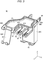
- FIG. 3 is a perspective view illustrating the mounting member 60 of the embodiment
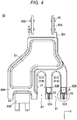
- FIG. 4 is a plan view illustrating the mounting member 60 of the embodiment
- FIG. 5 is an enlarged view of the portion A in FIG. 4 .
- the medical apparatus 1 can simultaneously perform measurements of vital signs (such as the blood pressure, the body temperature, the respiration, the pulse rate, and the arterial oxygen saturation), and ultrasonic diagnosis.
- the medical apparatus 1 may include: a post 10 that elongates in the vertical direction; casters 20 that are attached to the lower portion of the post 10; a housing section 30 that is attached to the post 10, and that houses a container of gel for ultrasonic measurement, and the like; a monitor 40 that is attached to the upper portion of the post 10; an ultrasonic measurement apparatus 50 for performing ultrasonic measurement; and a mounting member 60 on which the ultrasonic measurement apparatus 50 is mounted.
- the post 10, the casters 20, and the housing section 30 constitute a cart 5.
- the monitor 40 is fixed to the upper portion of the cart 5.
- the side in which the screen of the monitor 40 exists is referred to as the front side, and that in which the lateral surface of the monitor 40 exists is referred to as the lateral side.
- the post 10 is disposed so as to elongate in the vertical direction.
- a groove portion 11 that elongates in the vertical direction is disposed in the lateral surface of the post 10.
- An attachment portion 66 that is disposed in the mounting member 60 which will be described later is attached so as to be slidable in the vertical direction.
- the monitor 40 is attached to the upper portion of the cart 5.
- Various vital signs that are measured based on vital signs signals which are acquired from various sensors connected to a subject are displayed on the monitor 40.
- an ultrasonic image that is acquired by the ultrasonic measurement apparatus 50 is displayed on the monitor 40.
- the ultrasonic measurement apparatus 50 acquires an ultrasonic image of the interior of the body of the subject.
- the ultrasonic measurement apparatus 50 may include the probe 51 that is to be contacted with the body of the subject, and a remote controller 52 to which a connector part C2 that is disposed in one end of a cable C1 connected to the probe 51 is connected.
- the cable C1 connected to the probe 51 is, for example, a USB cable, and the remote controller 52 is USB-connected to the USB cable.
- the probe 51 may include: a transmitter (not shown) that is to be contacted with the body of the subject, and that transmits an ultrasonic wave; a receiver (not shown) that receives the ultrasonic wave which is reflected from the body of the subject; and a controller (not shown) to which a received ultrasonic wave signal is transmitted, and which acquires an ultrasonic image.
- the probe 51 may be any of the convex type, the sector type, and the linear type.
- the probe 51 may include an expanded portion 51A that is in the vicinity of the middle in the Z direction, and that extends in the X and Y directions. Since the expanded portion 51A is disposed in the probe 51 in this manner, the user can preferably grasp the probe 51. In the embodiment, two probes 51 are disposed.
- the cable C1 that is connected to the probe 51 is wound around a hooking portion 65 of the mounting member 60 that will be described later, to be hooked thereon.
- Another connector part C2 that is disposed in the other end of the cable C1 is connected to the remote controller 52.
- the remote controller 52 can perform activation and the like of the transmitter, receiver, and controller of the probe 51.
- a camera is incorporated in the remote controller 52, and can take an image of a situation of the scene.
- the ultrasonic image that is acquired by the ultrasonic measurement apparatus 50 is displayed on the monitor 40.
- the lateral direction in FIG. 4 is referred to as the X direction
- the vertical direction in FIG. 4 is referred to as the Y direction
- the direction perpendicular to the sheet is referred to as the Z direction.
- the ultrasonic measurement apparatus 50 is mounted on the mounting member 60.
- the mounting member 60 is detachably attached to the cart 5.
- the mounting member 60 may include; a planar portion 60A that is planarly configured along the XY plane; a first extended portion 60B that is extended from the left side of the planar portion 60A in the X direction, and the front side in the Y direction, and downward in the Z direction, and toward the front side in the Y direction; and a second extended portion 60C that is extended from the rear side of the planar portion 60A in the Y direction, and downward in the Z direction.
- the planar portion 60A and the first extended portion 60B are fixed to each other.
- the method of fixing together the planar portion 60A and the first extended portion 60B is not particularly limited.
- the planar portion 60A and the second extended portion 60C are fixed to each other.
- the method of fixing together the planar portion 60A and the second extended portion 60C is not particularly limited.
- the planar portion 60A is disposed in the XY plane.
- the material of the planar portion 60A is not particularly limited, the portion is configured by, for example, a resin.
- first mounting portions 61 on which the probes 51 are respectively mounted, fixing portions 62 to which the cables C1 connected to the probes 51 are respectively fixed, and a placing portion 63 on which small articles are to be placed are disposed in the planar portion 60A.
- the first mounting portions 61 have a shape that is recessed in a U-like manner toward the rear side in the Y direction. As illustrated in FIGS. 3 and 4 , two first mounting portions 61 are juxtaposed in the X direction so that the two probes 51 are mounted on the portions, respectively.
- the two first mounting portions 61 will be described in order to facilitate the description of the configurations of the first mounting portions 61. The description of the one first mounting portion 61 is applicable also to the other first mounting portion 61.
- the first mounting portion 61 is configured so that the length L1 (see FIG. 4 ) of the portion in the X direction is shorter than the X-direction length of the expanded portion 51A of each of the probes 51.
- the length L1 of the first mounting portion 61 in the X direction is longer than the X-direction length of the probe 51 excluding the expanded portion 51A.
- a tapered portion 61A is formed in the upper surface of the first mounting portion 61 so that the probe 51 is prevented from slipping off, and can be mounted from the upper side.
- the long sides 61B that constitute the portion, and that are opposed to each other are approximately parallel to each other.
- the probe 51 can be mounted so that the longitudinal direction of the probe 51 (the longitudinal direction as viewed from the upper side in FIG. 2 ) is oriented in the Y direction. Since the first mounting portion 61 is disposed as described above, the user can easily pick up the probe 51, and can quickly perform the inspection.
- the fixing portion 62 is disposed on the right side of the first mounting portion 61 in the X direction.
- the position where the fixing portion 62 is disposed is not limited to the above-described position.
- the fixing portion 62 may include constricted parts 62A each of which is configured so that its width is smaller than the width of the outer circumference of the cable C1 that is coated with a resin material, and a housing part 62B which is disposed on the rear side of the constricted parts 62A in the Y direction, and in which the connector part C2 connected to the cable C1 is housed and fixed.
- the housing part 62B has a structure that substantially corresponds to a USB cable, the structure is not necessarily limited to this.
- the housing part may have a structure that is configured considering the shape of another connector.
- the cable C1 is fixed to the constricted parts 62A of the fixing portion 62, and the connector part C2 is fixed to the housing part 62B of the fixing portion 62.
- the cable C1 is fixed to the constricted parts 62A of the fixing portion 62, also by the elastic force of the constricted parts 62A of the fixing portion 62.
- both the cable C1 and the connector part C2 are fixed as described above, only a part of the cable C1 may be fixed by using the constricted parts 62A. As illustrated in FIG. 5 , two constricted parts 62A are disposed in the fixing portion 62 along the Y direction.
- the cable C1 can be fixed at two places. Therefore, the cable C1 can be adequately prevented from slipping off.
- the disposition of the two constricted parts 62A in the fixing portion 62 along the Y direction allows the user to select one of the two constricted parts 62A, and fix the cable C1 by using the selected constricted part.
- the placing portion 63 is disposed in the rear side of the first mounting portion 61 in the Y direction and in the left side of the first mounting portion in the X direction.
- the small articles that are to be placed on the placing portion 63 are not particularly limited, and an example of the small articles is a container of gel for ultrasonic measurement.
- a second placing portion 64 on which the remote controller 52 of the ultrasonic measurement apparatus 50 is to be mounted is configured in the first extended portion 60B.
- the first extended portion 60B is configured by covering the circumference of a metal plate with a resin.
- the second placing portion 64 is disposed on the left side of the first mounting portion 61 in the X direction.
- the tip end of the second placing portion 64 has a U-like shape as viewed from the lateral side. According to the thus configured second placing portion 64, the remote controller 52 can be placed so that the operating surface of the remote controller is directed to the front side. Even when the user stands on either of the right and left sides of the medical apparatus 1, therefore, the user can view the operating surface of the remote controller 52, and therefore the operability of the user can be improved.
- the second extended portion 60C is configured by painting the circumference of a metal plate with a coating composition.
- the hooking portion 65 on which the cable C1 connected to the probe 51 is to be hooked, and the attachment portion 66 which is attached to the post 10 is attached are disposed in the second extended portion 60C.
- the cable C1 is hooked on the hooking portion 65 while being wound therearound.
- the hooking portion 65 is disposed in the lower part of the second extended portion 60C in the Z direction.
- the hooking portion 65 has a U-like shape as viewed from the lateral side. Since the hooking portion 65 is disposed in the mounting member 60 as described above, it is possible to prevent the cable C1 from being randomly placed.
- the hooking portion 65 is configured by covering the circumference of a metal plate with a resin.
- the attachment portion 66 is disposed in the rear side of the second extended portion 60C in the Y direction.
- the attachment portion 66 may include a pair of body parts 66A that extend toward the rear side in the Y direction, and fastening members 66B that are placed so as to be screwable into threaded holes (not shown) which are disposed in the body parts 66A.
- the pair of body parts 66A are disposed along the X direction. As illustrated in FIG. 2 , the pair of body parts 66A are separated from each other by a distance that is larger than the width of the post 10 in the X direction.
- Two fastening members 66B are disposed along the Y direction for each of the body parts 66A.
- the pair of body parts 66A are positioned in the Z direction under a state where the fastening members 66B are loosened so that the pair of body parts 66A can be slid in the Z direction, and thereafter the pair of fastening members 66B are fastened so as to approach to each other. This causes the fastening members 66B to be fixed to the post 10, thereby fixing the mounting member 60 to the post 10.
- the mounting member 60 is detachably attached to the cart 5.
- the mounting member 60 may be non-detachably attached to the cart 5.
- the two constricted parts 62A are disposed along the longitudinal direction of the cable C1.
- one or three or more constricted parts 62A may be disposed.
- first mounting portions 61 are disposed.
- one or three or more first mounting portions 61 may be disposed.
- the first mounting portions 61 have a shape that is recessed in a U-like manner toward the rear side in the Y direction.
- the first mounting portions 61 may have a rectangular shape or the like that is chamfered.
- the fixing portion 62 has the constricted parts 62A.
- a fixing portion 162 may have a configuration where constricted parts are not formed.
- the fixing portion 162 is configured so that its width is smaller than the width of the outer circumference of the cable C1 that is coated with a resin material. According to the configuration, the cable C1 is fixed to the fixing portion 162 by the elastic force of the resin material.
- the housing part 62B is configured so that the width in the X direction is larger than the width of the connector part C2.
- a fixing portion 262 may have a configuration where the cable C1 is not fixed to the fixing portion, but the connector part C2 is fitted into the fixing portion to be fixed thereto.
- the fixing portion 262 is configured by a groove having a substantially rectangular shape in a plan view that corresponds in width to the connector part C2.
- the cable C1 and the connector part C2 are illustrated in order to facilitate understanding of the configuration.
- the housing part 62B in which the connector part C2 connected to the cable C1 is to be housed is disposed on the rear side of the fixing portion 62 in the Y direction. As illustrated in FIG. 8 , however, the housing part 62B in which the connector part C2 is to be housed may not be disposed in a fixing portion 362.
- the fixing portion in the presently disclosed subject matter is not limited to have the above-described configurations, as far as the fixing portion is configured so that at least a part of the cable C1, at least a part of the connector part C2, or at least a part of the cable C1 and at least a part of the connector part C2 are fitted and fixed to the fixing portion.
- the connector part C2 is fixed to the housing part 62B.
- a configuration where the connector part C2 is not fixed to the housing part 62B, but simply housed therein may be employed.
- the fixing portion is disposed into which at least a part of the cable and connector part that are connected to the probe is fitted to be fixed thereto. Therefore, it is possible to prevent the cable connected to the probe from being randomly placed. In the case where measurements of vital signs, and ultrasonic diagnosis are to be simultaneously performed, consequently, the workability of the user can be improved.
- the first mounting portion is disposed on which a probe of the ultrasonic measurement apparatus is to be mounted along a vertical direction. Therefore, it is possible for the user to easily pick up the probe, and quickly perform the inspection. In the case where measurements of vital signs, and ultrasonic diagnosis are to be simultaneously performed, consequently, the workability of the user can be improved.
Landscapes
- Life Sciences & Earth Sciences (AREA)
- Health & Medical Sciences (AREA)
- Biomedical Technology (AREA)
- Biophysics (AREA)
- Nuclear Medicine, Radiotherapy & Molecular Imaging (AREA)
- Pathology (AREA)
- Radiology & Medical Imaging (AREA)
- Engineering & Computer Science (AREA)
- Physics & Mathematics (AREA)
- Heart & Thoracic Surgery (AREA)
- Medical Informatics (AREA)
- Molecular Biology (AREA)
- Surgery (AREA)
- Animal Behavior & Ethology (AREA)
- General Health & Medical Sciences (AREA)
- Public Health (AREA)
- Veterinary Medicine (AREA)
- Ultra Sonic Daignosis Equipment (AREA)
Abstract
Description
- The presently disclosed subject matter relates to a mounting member and a medical apparatus.
- Various vital signs (such as the blood pressure, the body temperature, the respiration, the pulse rate, and the arterial oxygen saturation) are widely used as information for knowing the condition of a subject.
- Recently, a technique has been proposed for simultaneously performing measurements of vital signs, and ultrasonic diagnosis using an ultrasonic measurement apparatus such as disclosed in
U.S. Patent Publication No. 2018/0168548 . In an emergency medical site, particularly, the condition in the body of the patient is first checked by using an ultrasonic measurement apparatus. - In the case where measurements of vital signs, and ultrasonic diagnosis are to be simultaneously performed, as described above, an ultrasonic measurement apparatus is combined with a related-art medical apparatus for acquiring vital signs. When a cable connected to a probe of the ultrasonic measurement apparatus is randomly placed, therefore, the workability of the user is poor. Consequently, it is requested to develop a mounting member on which an ultrasonic measurement apparatus is to be mounted, and which prevents a cable connected to a probe from being randomly placed.
- The invention has been conducted in order to solve the problem. It is an object of the presently disclosed subject matter to provide a mounting member and medical apparatus in which, in the case where measurements of vital signs, and ultrasonic diagnosis are to be simultaneously performed, the workability of the user can be improved.
- According to an aspect of the presently disclosed subject matter, there is provided a mounting member which is to be attached to a cart to which a monitor configured to display an ultrasonic image is fixed, the mounting member on which an ultrasonic measurement apparatus configured to acquire the ultrasonic image is to be mounted, the mounting member comprising: a fixing portion to which at least a part of a cable and connector part that are connected to a probe of the ultrasonic measurement apparatus is to be fitted and fixed.
- According to an aspect of the presently disclosed subject matter, there is also provided a mounting member which is to be attached to a cart to which a monitor configured to display an ultrasonic image is fixed, the mounting member on which an ultrasonic measurement apparatus configured to acquire the ultrasonic image is to be mounted, the mounting member comprising: a first mounting portion on which a probe of the ultrasonic measurement apparatus is to be mounted along a vertical direction.
- According to another aspect of the presently disclosed subject matter, there is provided a medical apparatus comprising: the above mounting member; the cart; the monitor; and the ultrasonic measurement apparatus.
-
-
FIG. 1 is a view schematically illustrating a medical apparatus of an embodiment. -
FIG. 2 is a perspective view illustrating a manner in which an ultrasonic measurement apparatus is mounted on a mounting member of the embodiment. -
FIG. 3 is a perspective view illustrating the mounting member of the embodiment. -
FIG. 4 is a plan view illustrating the mounting member of the embodiment. -
FIG. 5 is an enlarged view of the portion A inFIG. 4 . -
FIG. 6 illustrates a fixing portion inModification 1, and corresponds toFIG. 5 . -
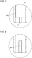
FIG. 7 illustrates a fixing portion in Modification 2, and corresponds toFIG. 5 . -
FIG. 8 illustrates a fixing portion in Modification 3, and corresponds toFIG. 5 . - An embodiment of the presently disclosed subject matter will be described with reference to the drawings. In the description of the drawings, identical components are denoted by the same reference numerals, and duplicated description is omitted. In the drawings, the dimension ratios are exaggerated for the sake of convenience in description, and may be sometimes different from the actual ratios.
-
FIG. 1 is a view schematically illustrating amedical apparatus 1 of the embodiment,FIG. 2 is a perspective view illustrating a manner in which an ultrasonic measurement apparatus 50 is mounted on amounting member 60 of the embodiment,FIG. 3 is a perspective view illustrating themounting member 60 of the embodiment,FIG. 4 is a plan view illustrating themounting member 60 of the embodiment, andFIG. 5 is an enlarged view of the portion A inFIG. 4 . - The
medical apparatus 1 can simultaneously perform measurements of vital signs (such as the blood pressure, the body temperature, the respiration, the pulse rate, and the arterial oxygen saturation), and ultrasonic diagnosis. As illustrated inFIG. 1 , themedical apparatus 1 may include: apost 10 that elongates in the vertical direction;casters 20 that are attached to the lower portion of thepost 10; ahousing section 30 that is attached to thepost 10, and that houses a container of gel for ultrasonic measurement, and the like; amonitor 40 that is attached to the upper portion of thepost 10; an ultrasonic measurement apparatus 50 for performing ultrasonic measurement; and amounting member 60 on which the ultrasonic measurement apparatus 50 is mounted. Thepost 10, thecasters 20, and thehousing section 30 constitute acart 5. Themonitor 40 is fixed to the upper portion of thecart 5. - In the following description, the side in which the screen of the
monitor 40 exists is referred to as the front side, and that in which the lateral surface of themonitor 40 exists is referred to as the lateral side. - As illustrated in
FIG. 1 , thepost 10 is disposed so as to elongate in the vertical direction. As illustrated inFIG. 2 , agroove portion 11 that elongates in the vertical direction is disposed in the lateral surface of thepost 10. Anattachment portion 66 that is disposed in themounting member 60 which will be described later is attached so as to be slidable in the vertical direction. - As illustrated in
FIG. 1 , fivecasters 20 are attached to the lower portion of thepost 10. Since thecasters 20 are attached in this way, themedical apparatus 1 can freely move on the floor. - As illustrated in
FIG. 1 , themonitor 40 is attached to the upper portion of thecart 5. Various vital signs that are measured based on vital signs signals which are acquired from various sensors connected to a subject are displayed on themonitor 40. Furthermore, an ultrasonic image that is acquired by the ultrasonic measurement apparatus 50 is displayed on themonitor 40. - When a
probe 51 is contacted with the body of the subject, the ultrasonic measurement apparatus 50 acquires an ultrasonic image of the interior of the body of the subject. As illustrated inFIG. 2 , the ultrasonic measurement apparatus 50 may include theprobe 51 that is to be contacted with the body of the subject, and aremote controller 52 to which a connector part C2 that is disposed in one end of a cable C1 connected to theprobe 51 is connected. The cable C1 connected to theprobe 51 is, for example, a USB cable, and theremote controller 52 is USB-connected to the USB cable. - The
probe 51 may include: a transmitter (not shown) that is to be contacted with the body of the subject, and that transmits an ultrasonic wave; a receiver (not shown) that receives the ultrasonic wave which is reflected from the body of the subject; and a controller (not shown) to which a received ultrasonic wave signal is transmitted, and which acquires an ultrasonic image. Theprobe 51 may be any of the convex type, the sector type, and the linear type. - As illustrated in
FIG. 2 , theprobe 51 may include an expandedportion 51A that is in the vicinity of the middle in the Z direction, and that extends in the X and Y directions. Since the expandedportion 51A is disposed in theprobe 51 in this manner, the user can preferably grasp theprobe 51. In the embodiment, twoprobes 51 are disposed. The cable C1 that is connected to theprobe 51 is wound around a hookingportion 65 of themounting member 60 that will be described later, to be hooked thereon. Another connector part C2 that is disposed in the other end of the cable C1 is connected to theremote controller 52. - Various operations can be remotely controlled through the
remote controller 52. For example, theremote controller 52 can perform activation and the like of the transmitter, receiver, and controller of theprobe 51. A camera is incorporated in theremote controller 52, and can take an image of a situation of the scene. - The ultrasonic image that is acquired by the ultrasonic measurement apparatus 50 is displayed on the
monitor 40. - With reference to
FIGS. 2 to 5 , next, the configuration of themounting member 60 will be described in detail. In order to facilitate the description, the lateral direction inFIG. 4 is referred to as the X direction, the vertical direction inFIG. 4 is referred to as the Y direction, and the direction perpendicular to the sheet is referred to as the Z direction. - As illustrated in
FIG. 2 , the ultrasonic measurement apparatus 50 is mounted on themounting member 60. Themounting member 60 is detachably attached to thecart 5. - As illustrated in
FIGS. 2 to 4 , themounting member 60 may include; aplanar portion 60A that is planarly configured along the XY plane; a first extendedportion 60B that is extended from the left side of theplanar portion 60A in the X direction, and the front side in the Y direction, and downward in the Z direction, and toward the front side in the Y direction; and a second extendedportion 60C that is extended from the rear side of theplanar portion 60A in the Y direction, and downward in the Z direction. - The
planar portion 60A and the first extendedportion 60B are fixed to each other. The method of fixing together theplanar portion 60A and the first extendedportion 60B is not particularly limited. Theplanar portion 60A and the second extendedportion 60C are fixed to each other. The method of fixing together theplanar portion 60A and the second extendedportion 60C is not particularly limited. - As illustrated in
FIGS. 3 and4 , theplanar portion 60A is disposed in the XY plane. Although the material of theplanar portion 60A is not particularly limited, the portion is configured by, for example, a resin. As illustrated inFIGS. 2 and3 , first mountingportions 61 on which theprobes 51 are respectively mounted, fixingportions 62 to which the cables C1 connected to theprobes 51 are respectively fixed, and a placingportion 63 on which small articles are to be placed are disposed in theplanar portion 60A. - As illustrated in
FIGS. 3 and4 , the first mountingportions 61 have a shape that is recessed in a U-like manner toward the rear side in the Y direction. As illustrated inFIGS. 3 and4 , two first mountingportions 61 are juxtaposed in the X direction so that the twoprobes 51 are mounted on the portions, respectively. Hereinafter, only one of the two first mountingportions 61 will be described in order to facilitate the description of the configurations of the first mountingportions 61. The description of the one first mountingportion 61 is applicable also to the other first mountingportion 61. - The first mounting
portion 61 is configured so that the length L1 (seeFIG. 4 ) of the portion in the X direction is shorter than the X-direction length of the expandedportion 51A of each of theprobes 51. The length L1 of the first mountingportion 61 in the X direction is longer than the X-direction length of theprobe 51 excluding the expandedportion 51A. A taperedportion 61A is formed in the upper surface of the first mountingportion 61 so that theprobe 51 is prevented from slipping off, and can be mounted from the upper side. In the first mountingportion 61, thelong sides 61B that constitute the portion, and that are opposed to each other are approximately parallel to each other. On the thus configured first mountingportion 61, theprobe 51 can be mounted so that the longitudinal direction of the probe 51 (the longitudinal direction as viewed from the upper side inFIG. 2 ) is oriented in the Y direction. Since the first mountingportion 61 is disposed as described above, the user can easily pick up theprobe 51, and can quickly perform the inspection. - As illustrated in
FIGS. 3 and4 , the fixingportion 62 is disposed on the right side of the first mountingportion 61 in the X direction. The position where the fixingportion 62 is disposed is not limited to the above-described position. - In the embodiment, the cable C1 connected to the
probe 51 is fixed by being fitted into the fixingportion 62. As illustrated inFIGS. 4 and5 , the fixingportion 62 may includeconstricted parts 62A each of which is configured so that its width is smaller than the width of the outer circumference of the cable C1 that is coated with a resin material, and ahousing part 62B which is disposed on the rear side of theconstricted parts 62A in the Y direction, and in which the connector part C2 connected to the cable C1 is housed and fixed. Although thehousing part 62B has a structure that substantially corresponds to a USB cable, the structure is not necessarily limited to this. The housing part may have a structure that is configured considering the shape of another connector. - Because of the elastic force of the resin material, therefore, the cable C1 is fixed to the
constricted parts 62A of the fixingportion 62, and the connector part C2 is fixed to thehousing part 62B of the fixingportion 62. In the case where theplanar portion 60A is made of a resin, the cable C1 is fixed to theconstricted parts 62A of the fixingportion 62, also by the elastic force of theconstricted parts 62A of the fixingportion 62. Although it is preferred that both the cable C1 and the connector part C2 are fixed as described above, only a part of the cable C1 may be fixed by using the constrictedparts 62A. As illustrated inFIG. 5 , two constrictedparts 62A are disposed in the fixingportion 62 along the Y direction. Since the two constrictedparts 62A of the fixingportion 62 are disposed in the Y direction as described above, the cable C1 can be fixed at two places. Therefore, the cable C1 can be adequately prevented from slipping off. The disposition of the two constrictedparts 62A in the fixingportion 62 along the Y direction allows the user to select one of the two constrictedparts 62A, and fix the cable C1 by using the selected constricted part. - Small articles are to be placed on the placing
portion 63. The placingportion 63 is disposed in the rear side of the first mountingportion 61 in the Y direction and in the left side of the first mounting portion in the X direction. The small articles that are to be placed on the placingportion 63 are not particularly limited, and an example of the small articles is a container of gel for ultrasonic measurement. - A
second placing portion 64 on which theremote controller 52 of the ultrasonic measurement apparatus 50 is to be mounted is configured in the firstextended portion 60B. The firstextended portion 60B is configured by covering the circumference of a metal plate with a resin. - The
second placing portion 64 is disposed on the left side of the first mountingportion 61 in the X direction. The tip end of thesecond placing portion 64 has a U-like shape as viewed from the lateral side. According to the thus configured second placingportion 64, theremote controller 52 can be placed so that the operating surface of the remote controller is directed to the front side. Even when the user stands on either of the right and left sides of themedical apparatus 1, therefore, the user can view the operating surface of theremote controller 52, and therefore the operability of the user can be improved. - The second
extended portion 60C is configured by painting the circumference of a metal plate with a coating composition. The hookingportion 65 on which the cable C1 connected to theprobe 51 is to be hooked, and theattachment portion 66 which is attached to thepost 10 is attached are disposed in the secondextended portion 60C. - As illustrated in
FIG. 2 , the cable C1 is hooked on the hookingportion 65 while being wound therearound. The hookingportion 65 is disposed in the lower part of the secondextended portion 60C in the Z direction. The hookingportion 65 has a U-like shape as viewed from the lateral side. Since the hookingportion 65 is disposed in the mountingmember 60 as described above, it is possible to prevent the cable C1 from being randomly placed. The hookingportion 65 is configured by covering the circumference of a metal plate with a resin. - As illustrated in
FIGS. 2 to 4 , theattachment portion 66 is disposed in the rear side of the secondextended portion 60C in the Y direction. Theattachment portion 66 may include a pair ofbody parts 66A that extend toward the rear side in the Y direction, andfastening members 66B that are placed so as to be screwable into threaded holes (not shown) which are disposed in thebody parts 66A. - The pair of
body parts 66A are disposed along the X direction. As illustrated inFIG. 2 , the pair ofbody parts 66A are separated from each other by a distance that is larger than the width of thepost 10 in the X direction. - Two
fastening members 66B are disposed along the Y direction for each of thebody parts 66A. The pair ofbody parts 66A are positioned in the Z direction under a state where thefastening members 66B are loosened so that the pair ofbody parts 66A can be slid in the Z direction, and thereafter the pair offastening members 66B are fastened so as to approach to each other. This causes thefastening members 66B to be fixed to thepost 10, thereby fixing the mountingmember 60 to thepost 10. - The presently disclosed subject matter is not limited to the embodiment, and the configuration may be variously modified within the scope of the accompanying claims.
- In the above-described embodiment, for example, the mounting
member 60 is detachably attached to thecart 5. However, the mountingmember 60 may be non-detachably attached to thecart 5. - In the above-described embodiment, moreover, the two constricted
parts 62A are disposed along the longitudinal direction of the cable C1. However, one or three or moreconstricted parts 62A may be disposed. - In the above-described embodiment, moreover, the two first mounting
portions 61 are disposed. However, one or three or more first mountingportions 61 may be disposed. - In the above-described embodiment, moreover, the first mounting
portions 61 have a shape that is recessed in a U-like manner toward the rear side in the Y direction. However, the first mountingportions 61 may have a rectangular shape or the like that is chamfered. - In the above-described embodiment, as illustrated in
FIG. 5 , the fixingportion 62 has the constrictedparts 62A. As illustrated inFIG. 6 , however, a fixingportion 162 may have a configuration where constricted parts are not formed. In this case, the fixingportion 162 is configured so that its width is smaller than the width of the outer circumference of the cable C1 that is coated with a resin material. According to the configuration, the cable C1 is fixed to the fixingportion 162 by the elastic force of the resin material. - In the above-described embodiment, moreover, the
housing part 62B is configured so that the width in the X direction is larger than the width of the connector part C2. As illustrated inFIG. 7 , however, a fixingportion 262 may have a configuration where the cable C1 is not fixed to the fixing portion, but the connector part C2 is fitted into the fixing portion to be fixed thereto. In the modification, the fixingportion 262 is configured by a groove having a substantially rectangular shape in a plan view that corresponds in width to the connector part C2. InFIG. 7 , the cable C1 and the connector part C2 are illustrated in order to facilitate understanding of the configuration. - In the above-described embodiment, as illustrated in
FIG. 4 , thehousing part 62B in which the connector part C2 connected to the cable C1 is to be housed is disposed on the rear side of the fixingportion 62 in the Y direction. As illustrated inFIG. 8 , however, thehousing part 62B in which the connector part C2 is to be housed may not be disposed in a fixingportion 362. - The fixing portion in the presently disclosed subject matter is not limited to have the above-described configurations, as far as the fixing portion is configured so that at least a part of the cable C1, at least a part of the connector part C2, or at least a part of the cable C1 and at least a part of the connector part C2 are fitted and fixed to the fixing portion.
- In the above-described embodiment, the connector part C2 is fixed to the
housing part 62B. However, a configuration where the connector part C2 is not fixed to thehousing part 62B, but simply housed therein may be employed. - According to the mounting member and medical apparatus that are described above, the fixing portion is disposed into which at least a part of the cable and connector part that are connected to the probe is fitted to be fixed thereto. Therefore, it is possible to prevent the cable connected to the probe from being randomly placed. In the case where measurements of vital signs, and ultrasonic diagnosis are to be simultaneously performed, consequently, the workability of the user can be improved.
- According to the mounting member and medical apparatus that are described above, the first mounting portion is disposed on which a probe of the ultrasonic measurement apparatus is to be mounted along a vertical direction. Therefore, it is possible for the user to easily pick up the probe, and quickly perform the inspection. In the case where measurements of vital signs, and ultrasonic diagnosis are to be simultaneously performed, consequently, the workability of the user can be improved.
Claims (15)
- A mounting member which is to be attached to a cart to which a monitor configured to display an ultrasonic image is fixed, the mounting member on which an ultrasonic measurement apparatus configured to acquire the ultrasonic image is to be mounted, the mounting member comprising:
a fixing portion to which at least a part of a cable and connector part that are connected to a probe of the ultrasonic measurement apparatus is to be fitted and fixed. - The mounting member according to claim 1, wherein the fixing portion has a constricted part into which the cable is to be fitted.
- The mounting member according to claim 2, wherein two constricted parts are disposed along a longitudinal direction of the cable.
- The mounting member according to any one of claims 1 to 3, further comprising:
a first mounting portion on which the probe is to be mounted along a vertical direction. - The mounting member according to claim 4, wherein long sides that constitute the first mounting portion, and that are opposed to each other are approximately parallel to each other.
- The mounting member according to claim 4 or 5, wherein a tapered portion is formed in an upper surface of the first mounting portion, to enable the probe to be prevented from slipping off, and to be mounted from an upper side.
- The mounting member according to any one of claims 1 to 6, further comprising:
a second mounting portion on which a remote controller of the ultrasonic measurement apparatus is to be mounted so that an operating surface of the remote controller is directed toward a screen of the monitor. - A mounting member which is to be attached to a cart to which a monitor configured to display an ultrasonic image is fixed, the mounting member on which an ultrasonic measurement apparatus configured to acquire the ultrasonic image is to be mounted, the mounting member comprising:
a first mounting portion on which a probe of the ultrasonic measurement apparatus is to be mounted along a vertical direction. - The mounting member according to claim 8, further comprising:
a fixing portion to which at least a part of a cable and connector part that are connected to a probe of the ultrasonic measurement apparatus is to be fitted and fixed. - The mounting member according to claim 9, wherein the fixing portion has a constricted part into which the cable is to be fitted.
- The mounting member according to claim 10, wherein two constricted parts are disposed along a longitudinal direction of the cable.
- The mounting member according to claim 8, wherein long sides that constitute the first mounting portion, and that are opposed to each other are approximately parallel to each other.
- The mounting member according to claim 8 or 12, wherein a tapered portion is formed in an upper surface of the first mounting portion, to enable the probe to be prevented from slipping off, and to be mounted from an upper side.
- The mounting member according to any one of claims 8 to 13, further comprising:
a second mounting portion on which a remote controller of the ultrasonic measurement apparatus is to be mounted so that an operating surface of the remote controller is directed toward a screen of the monitor. - A medical apparatus comprising:the mounting member according to any one of claims 1 to 14;the cart;the monitor; andthe ultrasonic measurement apparatus.
Applications Claiming Priority (1)
| Application Number | Priority Date | Filing Date | Title |
|---|---|---|---|
| JP2019098087A JP7289724B2 (en) | 2019-05-24 | 2019-05-24 | Placement member and medical device |
Publications (1)
| Publication Number | Publication Date |
|---|---|
| EP3741302A1 true EP3741302A1 (en) | 2020-11-25 |
Family
ID=70802570
Family Applications (1)
| Application Number | Title | Priority Date | Filing Date |
|---|---|---|---|
| EP20172232.9A Pending EP3741302A1 (en) | 2019-05-24 | 2020-04-30 | Mounting member and medical apparatus |
Country Status (3)
| Country | Link |
|---|---|
| US (1) | US12285290B2 (en) |
| EP (1) | EP3741302A1 (en) |
| JP (1) | JP7289724B2 (en) |
Families Citing this family (7)
| Publication number | Priority date | Publication date | Assignee | Title |
|---|---|---|---|---|
| USD915603S1 (en) * | 2019-09-23 | 2021-04-06 | GE Precision Healthcare LLC | Accessory holder |
| JP7491729B2 (en) * | 2020-04-30 | 2024-05-28 | 富士フイルムヘルスケア株式会社 | Ultrasound diagnostic equipment |
| JP7501331B2 (en) | 2020-12-02 | 2024-06-18 | コニカミノルタ株式会社 | Ultrasound probe holder, ultrasound diagnostic device, cart for ultrasound diagnostic device, and ultrasound diagnostic system |
| US12076185B2 (en) * | 2021-02-03 | 2024-09-03 | GE Precision Healthcare LLC | Reversible cart mounted storage bin |
| CN113558776B (en) * | 2021-07-31 | 2023-06-20 | 绍兴市人民医院 | An ultrasonic instrument stabilizer in an emergency vehicle |
| US20250222583A1 (en) * | 2021-10-20 | 2025-07-10 | Brian Sciabarrasi | Tool belt stand |
| JP7821644B2 (en) * | 2022-03-18 | 2026-02-27 | フクダ電子株式会社 | Medical trolley |
Citations (6)
| Publication number | Priority date | Publication date | Assignee | Title |
|---|---|---|---|---|
| EP2243430A1 (en) * | 2009-04-22 | 2010-10-27 | Medison Co., Ltd. | Probe holder |
| US20140117635A1 (en) * | 2011-09-30 | 2014-05-01 | Hitachi Aloka Medical, Ltd. | Cart for portable ultrasonic diagnostic device and ultrasonic diagnostic unit |
| WO2014207593A1 (en) * | 2013-06-28 | 2014-12-31 | Koninklijke Philips N.V. | Cable management systems for cart-borne ultrasonic diagnostic imaging systems |
| US20150320298A1 (en) * | 2014-05-07 | 2015-11-12 | Emil D. Missov | Holder for a transesophageal echocardiography probe |
| WO2018083519A1 (en) * | 2016-11-03 | 2018-05-11 | B-K Medical Aps | Probe cable support |
| US20180168548A1 (en) | 2012-03-26 | 2018-06-21 | Teratech Corporation | Tablet ultrasound system |
Family Cites Families (24)
| Publication number | Priority date | Publication date | Assignee | Title |
|---|---|---|---|---|
| US4609171A (en) * | 1983-09-05 | 1986-09-02 | Kitagawa Industries Co., Ltd. | Electric wire bundle clamp |
| US5673696A (en) * | 1995-09-28 | 1997-10-07 | Siemens Medical Systems Inc. | Ultrasound transducer probe holder |
| US6629927B1 (en) * | 2002-05-23 | 2003-10-07 | Koninklijke Philips Electronics N.V. | Diagnostic ultrasound system cart with integral cable supports |
| US6821250B2 (en) | 2002-05-23 | 2004-11-23 | Koninklijke Philips Electronics N.V. | Diagnostic ultrasound system cart with movable probe holders |
| EP1804668B1 (en) * | 2004-10-18 | 2012-05-23 | Mobile Robotics Sweden AB | Robot for ultrasonic examination |
| US20080146922A1 (en) * | 2006-10-24 | 2008-06-19 | Zonare Medical Systems, Inc. | Control of user interfaces and displays for portable ultrasound unit and docking station |
| CN101841080B (en) * | 2010-02-02 | 2013-03-20 | 鸿富锦精密工业(深圳)有限公司 | Antenna shielding device and antenna clip thereof |
| JP5558920B2 (en) | 2010-05-26 | 2014-07-23 | 日立アロカメディカル株式会社 | Ultrasonic diagnostic equipment |
| US8128050B1 (en) * | 2011-02-08 | 2012-03-06 | Sonosite, Inc. | Ultrasound scanner support devices |
| JP6085091B2 (en) | 2012-02-23 | 2017-02-22 | 株式会社日立製作所 | Cart for portable ultrasonic diagnostic equipment, portable ultrasonic unit |
| US20140088420A1 (en) * | 2012-09-27 | 2014-03-27 | Glen Thomas Lindahl | Transducer Storage Rack |
| KR102250094B1 (en) | 2013-12-23 | 2021-05-10 | 삼성전자주식회사 | Method for performing function and mobile apparatus using the method |
| DE102014001382A1 (en) * | 2014-02-01 | 2015-08-06 | GM Global Technology Operations LLC (n. d. Ges. d. Staates Delaware) | Retaining clip for at least one elongated component |
| EP4170839A1 (en) * | 2015-03-27 | 2023-04-26 | CommScope Technologies LLC | Cable hanger |
| US10948107B2 (en) * | 2015-10-30 | 2021-03-16 | Commscope Technologies Llc | Hanger for mounting cables |
| US20190125064A1 (en) * | 2017-10-27 | 2019-05-02 | Butterfly Network, Inc. | Holster for ultrasound imaging device |
| KR20190052789A (en) * | 2017-11-09 | 2019-05-17 | 삼성메디슨 주식회사 | Ultrasonic imaging device and controlling method thereof |
| JP2019126454A (en) * | 2018-01-23 | 2019-08-01 | コニカミノルタ株式会社 | Ultrasound probe holder |
| KR20190102598A (en) * | 2018-02-26 | 2019-09-04 | 삼성메디슨 주식회사 | Ultrasound diagnosis apparatus and cable supportingapparatus for the same |
| US20190380681A1 (en) * | 2018-06-14 | 2019-12-19 | General Electric Company | Method and systems for a portable ultrasound imaging system |
| US11793486B2 (en) * | 2018-08-21 | 2023-10-24 | General Electric Company | Ultrasound system probe holder |
| DE102018216274B4 (en) * | 2018-09-25 | 2021-07-01 | Audi Ag | Fastening strip, method for producing a fastening strip and method for fastening an elongate structural element |
| US20200315573A1 (en) * | 2019-04-02 | 2020-10-08 | Samsung Medison Co., Ltd. | Ultrasound diagnositic apparatus and control method thereof |
| JP7478119B2 (en) * | 2021-05-27 | 2024-05-02 | 富士フイルムヘルスケア株式会社 | Probe Holder |
-
2019
- 2019-05-24 JP JP2019098087A patent/JP7289724B2/en active Active
-
2020
- 2020-04-28 US US16/860,163 patent/US12285290B2/en active Active
- 2020-04-30 EP EP20172232.9A patent/EP3741302A1/en active Pending
Patent Citations (6)
| Publication number | Priority date | Publication date | Assignee | Title |
|---|---|---|---|---|
| EP2243430A1 (en) * | 2009-04-22 | 2010-10-27 | Medison Co., Ltd. | Probe holder |
| US20140117635A1 (en) * | 2011-09-30 | 2014-05-01 | Hitachi Aloka Medical, Ltd. | Cart for portable ultrasonic diagnostic device and ultrasonic diagnostic unit |
| US20180168548A1 (en) | 2012-03-26 | 2018-06-21 | Teratech Corporation | Tablet ultrasound system |
| WO2014207593A1 (en) * | 2013-06-28 | 2014-12-31 | Koninklijke Philips N.V. | Cable management systems for cart-borne ultrasonic diagnostic imaging systems |
| US20150320298A1 (en) * | 2014-05-07 | 2015-11-12 | Emil D. Missov | Holder for a transesophageal echocardiography probe |
| WO2018083519A1 (en) * | 2016-11-03 | 2018-05-11 | B-K Medical Aps | Probe cable support |
Also Published As
| Publication number | Publication date |
|---|---|
| US12285290B2 (en) | 2025-04-29 |
| US20200367857A1 (en) | 2020-11-26 |
| JP2020191985A (en) | 2020-12-03 |
| JP7289724B2 (en) | 2023-06-12 |
Similar Documents
| Publication | Publication Date | Title |
|---|---|---|
| US12285290B2 (en) | Mounting member and medical apparatus | |
| US20090259106A1 (en) | Retractor system for surgical applications for detecting characteristic parameters of organic tissues | |
| KR102372151B1 (en) | Medical holding arm with annular LED display means | |
| US20250302444A1 (en) | Patient monitor, physiological information measurement system, program to be used in patient monitor, and non-transitory computer readable medium in which program to be used in patient monitor is stored | |
| US20180199914A1 (en) | Fiber-optic realshape sensor for enhanced dopper measurement display | |
| WO2006076409A3 (en) | Vascular image co-registration | |
| CN102551876A (en) | Zero-drift detection and correction in contact force measurements | |
| WO1997029709B1 (en) | Medical procedures and apparatus using intrabody probes | |
| US20080139916A1 (en) | Determining the length of a long, flexible instrument | |
| EP2636370A2 (en) | Airway adaptor and biological information acquiring system | |
| CA3017070C (en) | System and method for sensing tissue deformation | |
| JP2019098172A (en) | Low profile dual pad magnetic field location system with self tracking | |
| US20250006340A1 (en) | System and Method for Controlling Operability of Multiple Medical Devices | |
| CN112914521B (en) | Apparatus and method for intravascular measurements | |
| US9372126B2 (en) | Low-complexity optical force sensor for a medical device | |
| EP3195792A1 (en) | Optical transmitter unit, method for connecting optical transmitter module and transmission-side optical connector, and endoscope system | |
| EP2859846A1 (en) | Sensor and shape retainer | |
| US20170325742A1 (en) | Universal fingertip sensor | |
| US20230140407A1 (en) | Data and power transfer devices for use with medical devices and related methods | |
| US9198558B2 (en) | Harness for medical device and method for assembling medical device | |
| US20160360950A1 (en) | Medical instrument, medical system, and mode transition method for medical instruments | |
| CN114159108B (en) | A robotic surgical retractor capable of realizing precise force perception and a method of using the same | |
| JP4963067B2 (en) | Compressive force measuring device | |
| JP7065592B2 (en) | Ultrasonic probe, ultrasonic measurement system | |
| WO2007036380A1 (en) | Patient-securing strap and patient-supporting device |
Legal Events
| Date | Code | Title | Description |
|---|---|---|---|
| PUAI | Public reference made under article 153(3) epc to a published international application that has entered the european phase |
Free format text: ORIGINAL CODE: 0009012 |
|
| STAA | Information on the status of an ep patent application or granted ep patent |
Free format text: STATUS: THE APPLICATION HAS BEEN PUBLISHED |
|
| AK | Designated contracting states |
Kind code of ref document: A1 Designated state(s): AL AT BE BG CH CY CZ DE DK EE ES FI FR GB GR HR HU IE IS IT LI LT LU LV MC MK MT NL NO PL PT RO RS SE SI SK SM TR |
|
| AX | Request for extension of the european patent |
Extension state: BA ME |
|
| STAA | Information on the status of an ep patent application or granted ep patent |
Free format text: STATUS: REQUEST FOR EXAMINATION WAS MADE |
|
| 17P | Request for examination filed |
Effective date: 20210519 |
|
| RBV | Designated contracting states (corrected) |
Designated state(s): AL AT BE BG CH CY CZ DE DK EE ES FI FR GB GR HR HU IE IS IT LI LT LU LV MC MK MT NL NO PL PT RO RS SE SI SK SM TR |
|
| STAA | Information on the status of an ep patent application or granted ep patent |
Free format text: STATUS: EXAMINATION IS IN PROGRESS |
|
| 17Q | First examination report despatched |
Effective date: 20230317 |