EP3740944B1 - Apparatus and system for temperature measurement for dry-type transformer - Google Patents
Apparatus and system for temperature measurement for dry-type transformer Download PDFInfo
- Publication number
- EP3740944B1 EP3740944B1 EP18900850.1A EP18900850A EP3740944B1 EP 3740944 B1 EP3740944 B1 EP 3740944B1 EP 18900850 A EP18900850 A EP 18900850A EP 3740944 B1 EP3740944 B1 EP 3740944B1
- Authority
- EP
- European Patent Office
- Prior art keywords
- dry
- type transformer
- measuring apparatus
- wireless communication
- communication module
- Prior art date
- Legal status (The legal status is an assumption and is not a legal conclusion. Google has not performed a legal analysis and makes no representation as to the accuracy of the status listed.)
- Active
Links
Images


Classifications
-
- G—PHYSICS
- G01—MEASURING; TESTING
- G01K—MEASURING TEMPERATURE; MEASURING QUANTITY OF HEAT; THERMALLY-SENSITIVE ELEMENTS NOT OTHERWISE PROVIDED FOR
- G01K1/00—Details of thermometers not specially adapted for particular types of thermometer
- G01K1/02—Means for indicating or recording specially adapted for thermometers
- G01K1/024—Means for indicating or recording specially adapted for thermometers for remote indication
-
- G—PHYSICS
- G01—MEASURING; TESTING
- G01K—MEASURING TEMPERATURE; MEASURING QUANTITY OF HEAT; THERMALLY-SENSITIVE ELEMENTS NOT OTHERWISE PROVIDED FOR
- G01K1/00—Details of thermometers not specially adapted for particular types of thermometer
- G01K1/14—Supports; Fastening devices; Arrangements for mounting thermometers in particular locations
-
- G—PHYSICS
- G01—MEASURING; TESTING
- G01K—MEASURING TEMPERATURE; MEASURING QUANTITY OF HEAT; THERMALLY-SENSITIVE ELEMENTS NOT OTHERWISE PROVIDED FOR
- G01K3/00—Thermometers giving results other than momentary value of temperature
- G01K3/005—Circuits arrangements for indicating a predetermined temperature
-
- G—PHYSICS
- G05—CONTROLLING; REGULATING
- G05B—CONTROL OR REGULATING SYSTEMS IN GENERAL; FUNCTIONAL ELEMENTS OF SUCH SYSTEMS; MONITORING OR TESTING ARRANGEMENTS FOR SUCH SYSTEMS OR ELEMENTS
- G05B15/00—Systems controlled by a computer
- G05B15/02—Systems controlled by a computer electric
-
- H—ELECTRICITY
- H01—ELECTRIC ELEMENTS
- H01F—MAGNETS; INDUCTANCES; TRANSFORMERS; SELECTION OF MATERIALS FOR THEIR MAGNETIC PROPERTIES
- H01F27/00—Details of transformers or inductances, in general
- H01F27/08—Cooling; Ventilating
- H01F27/085—Cooling by ambient air
-
- H—ELECTRICITY
- H01—ELECTRIC ELEMENTS
- H01F—MAGNETS; INDUCTANCES; TRANSFORMERS; SELECTION OF MATERIALS FOR THEIR MAGNETIC PROPERTIES
- H01F27/00—Details of transformers or inductances, in general
- H01F27/28—Coils; Windings; Conductive connections
- H01F27/32—Insulating of coils, windings, or parts thereof
- H01F27/327—Encapsulating or impregnating
-
- H—ELECTRICITY
- H01—ELECTRIC ELEMENTS
- H01F—MAGNETS; INDUCTANCES; TRANSFORMERS; SELECTION OF MATERIALS FOR THEIR MAGNETIC PROPERTIES
- H01F27/00—Details of transformers or inductances, in general
- H01F27/40—Structural association with built-in electric component, e.g. fuse
-
- H—ELECTRICITY
- H01—ELECTRIC ELEMENTS
- H01F—MAGNETS; INDUCTANCES; TRANSFORMERS; SELECTION OF MATERIALS FOR THEIR MAGNETIC PROPERTIES
- H01F27/00—Details of transformers or inductances, in general
- H01F27/40—Structural association with built-in electric component, e.g. fuse
- H01F27/402—Association of measuring or protective means
-
- H—ELECTRICITY
- H04—ELECTRIC COMMUNICATION TECHNIQUE
- H04Q—SELECTING
- H04Q9/00—Arrangements in telecontrol or telemetry systems for selectively calling a substation from a main station, in which substation desired apparatus is selected for applying a control signal thereto or for obtaining measured values therefrom
-
- H—ELECTRICITY
- H01—ELECTRIC ELEMENTS
- H01F—MAGNETS; INDUCTANCES; TRANSFORMERS; SELECTION OF MATERIALS FOR THEIR MAGNETIC PROPERTIES
- H01F27/00—Details of transformers or inductances, in general
- H01F27/28—Coils; Windings; Conductive connections
- H01F27/32—Insulating of coils, windings, or parts thereof
- H01F27/327—Encapsulating or impregnating
- H01F2027/328—Dry-type transformer with encapsulated foil winding, e.g. windings coaxially arranged on core legs with spacers for cooling and with three phases
-
- H—ELECTRICITY
- H01—ELECTRIC ELEMENTS
- H01F—MAGNETS; INDUCTANCES; TRANSFORMERS; SELECTION OF MATERIALS FOR THEIR MAGNETIC PROPERTIES
- H01F27/00—Details of transformers or inductances, in general
- H01F27/40—Structural association with built-in electric component, e.g. fuse
- H01F27/402—Association of measuring or protective means
- H01F2027/406—Temperature sensor or protection
-
- H—ELECTRICITY
- H04—ELECTRIC COMMUNICATION TECHNIQUE
- H04Q—SELECTING
- H04Q2209/00—Arrangements in telecontrol or telemetry systems
- H04Q2209/40—Arrangements in telecontrol or telemetry systems using a wireless architecture
- H04Q2209/47—Arrangements in telecontrol or telemetry systems using a wireless architecture using RFID associated with sensors
Definitions
- Example embodiments disclosed herein generally relate to temperature measurement and more particularly, to a measuring apparatus and system for measuring a temperature of a dry-type transformer.
- a transformer is an electrical device that transfers electrical energy between two or more circuits through electromagnetic induction, and the transformer is generally divided into an oil-type transformer and a dry-type transformer (also referred to as dry transformer).
- the oil-type transformer uses insulation oil as the insulation material, while the dry-type transformer is one in which the transformer core and coils are not immersed in a liquid. That is, in the dry-type transformer, air is used as the cooling medium instead of oil.
- the dry-type transformer can be designed to operate at higher temperatures than oil-type transformer.
- a temperature of the dry-type transformer may rise as high as for example 180 °C.
- Example embodiments disclosed herein propose a solution for measuring temperature of the dry-type transformer using a passive wireless measuring apparatus.
- example embodiments disclosed herein provide a measuring apparatus.
- the measuring apparatus according to the present invention comprises a temperature sensor configured to measure a temperature of a dry-type transformer, wherein the temperature sensor is configured to be arranged on or proximate to a conductor of the dry-type transformer and to be covered by an insulating layer of the conductor.
- the measuring apparatus according to the present invention further comprises a passive wireless communication module configured to transmit the measured temperature to a reader.
- the insulating layer is formed by wrapping an insulating material, preferably an epoxy resin, on the conductor and the temperature sensor, and the conductor is one of the following: a high voltage (HV) winding of the dry-type transformer, a low voltage (LV) winding of the dry-type transformer, a core of the dry-type transformer, and a tap terminal of the dry-type transformer.
- HV high voltage
- LV low voltage
- the passive wireless communication module is connected to the temperature sensor via a wire, and one end of the wire protrudes from the insulating layer.
- the temperature sensor is arranged on an upper part of the HV winding or the LV winding along the core.
- the passive wireless communication module is arranged on or inside a dome area of the HV winding, and preferably, near a tap changer or a wire connection terminal on the dome area.
- the passive wireless communication module is covered by an insulating layer of the dome area, or arranged inside a groove of the dome area, and a part of the wire is arranged in the groove for connecting the passive wireless communication module and the temperature sensor.
- the temperature sensor is connected to the conductor via a thermally conductive layer within the insulating layer.
- the temperature sensor is packaged inside the passive wireless communication module, and a terminal of the temperature sensor is exposed outside the passive wireless communication module.
- the insulating layer is formed by wrapping an insulating material, preferably an epoxy resin, on the conductor and the passive wireless communication module.
- the measuring apparatus is made of soft material and arranged on a curved surface of the dry-type transformer, preferably covered by an insulating layer of the curved surface.
- the passive wireless communication module includes a passive radio frequency identification (RFID) tag or a surface acoustic wave (SAW) tag.
- RFID radio frequency identification
- SAW surface acoustic wave
- example embodiments disclosed herein provide a system for measuring a temperature of a dry-type transformer.
- the system comprises the measuring apparatus of the first aspect, the reader, and the dry-type transformer.
- the reader is arranged inside the dry-type transformer, preferably in a low voltage (LV) compartment of the dry-type transformer.
- LV low voltage
- the reader is configured to provide wireless radio frequency energy to power the measuring apparatus via one or more antennas.
- the system further comprises one or more antennas configured to receive the measured temperature from the passive wireless communication module, and at least one of the one or more antennas is arranged in middle of the dry-type transformer to enable a wireless communication between the at least one antenna and the passive wireless communication module.
- the system further comprises a further measuring apparatus of the first aspect arranged at a different location from the measuring apparatus.
- system further comprises a controller configured to, in response to the measured temperature being above a predefined threshold, turn on a cooling device to decrease the temperature of the dry-type transformer.
- example embodiments disclosed herein provide use of measuring apparatus of the first aspect for measuring a temperature of a dry-type transformer.
- example embodiments disclosed herein provide a method for installing a measuring apparatus.
- the method comprises assembling the temperature sensor of the measuring apparatus of the first aspect to a surface of a conductor of a dry-type transformer and wrapping an insulating material on the conductor and the temperature sensor such that the temperature sensor is non-detachable.
- example embodiments disclosed herein provide a method for detaching a measuring apparatus.
- the method comprises detaching the passive wireless communication module of the measuring apparatus of the first aspect from a groove of a dome area.
- the method further comprises assembling a new passive wireless communication module in the groove of the dome area and connecting the new passive wireless communication module to a wire which is arranged in the groove.
- the temperature of the dry-type transformer can be measured accurately, thereby improving the reliability and safety of the dry-type transformer. Accordingly, the temperature measurement for the dry-type transformer can work appropriately in a cost-effective and efficient way.
- a wired thermal couple is used to measure a temperature of the dry-type transformer, and the measuring probe is generally located in the air duct.
- the wired measuring apparatus is very inconvenient, which will cause the line arrangement to be complex, and a battery is often required to power the wired measuring apparatus.
- traditional measuring apparatus cannot obtain the accurate temperature of the dry-type transformer and the hot pot temperature the dry-type transformer, and it is generally costly to measure the temperature of the dry-type transformer. Accordingly, traditional ways for measuring the temperature of the dry-type transformer are inaccurate and inefficient.
- a measuring apparatus and system for measuring a temperature of a dry-type transformer which can measure the temperature of the dry-type transformer accurately.
- the proposed measuring apparatus is passive and wireless; thus, the measuring apparatus can be arranged flexibly in the dry-type transformer, and the reliability and safety of the dry-type transformer can be also improved. Accordingly, according to embodiments of the present disclosure, temperature measurement for dry-type transformer can work in a cost-effective and efficient way.
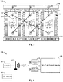
- Fig. 1 illustrates a schematic diagram of an example of a dry-type transformer 100.
- the dry-type transformer 100 is a three-phase dry-type transformer with the cabinet removed, which uses three groups of conductors to generated three-phase alternating current.
- Each of the three groups comprises a core, a low voltage (LV) winding or coil (not shown), and a high voltage (HV) winding or coil.
- the first group comprises a core 110 and a HV winding 111
- the second group comprises a core 120 and a HV winding 121
- the third group comprises a core 130 and a HV winding 131.
- the dry-type transformer 100 uses air as the cooling medium instead of oil, insulation is necessary between conductors of dry-type transformer 100, and thus each conductor may be casted with an insulating layer.
- a varying current in one winding produces a varying magnetic field, which in turn induces a voltage in another winding. Accordingly, power can be transferred between the windings through the magnetic field without a metallic connection between the windings.
- the dry-type transformer 100 further comprises an upper clamp 140 and a lower clamp 150.
- the upper clamp 140 there are arranged with a plurality of HV terminals, such as HV terminals 141, 142 and 143.
- One or more cooling devices are arranged near the lower clamp 150 so as to cool the dry-type transformer 100 together or separately. Examples of the cooling devices comprise, but are not limited to, fans 151, 152 and 153.
- the dry-type transformer 100 can comprise one or more further components other than those as shown in Fig. 1 . Additionally, although the three-phase dry-type transformer is shown as an example, other-phase (such as a single-phase) dry-type transformer may be also possible.
- Fig. 2 illustrates a schematic diagram of an environment 200 in which a measuring apparatus is used to measure a temperature of a dry-type transformer.
- a measuring apparatus 210 is used to measure a temperature of a conductor 240
- the conductor 240 may be any conductor in the dry-type transformer 100 with reference to Fig. 1 , including but not limited to the HV windings 111, 121, 131 of the dry-type transformer 100, the LV windings of the dry-type transformer 100, the cores 110, 120, 130 of the dry-type transformer 100, tap terminals, HV outlets, LV outlets and so on.
- the measuring apparatus 210 comprises a temperature sensor 220 and a passive wireless communication module 230.
- the temperature sensor 220 is configured to measure a temperate of a location of the dry-type transformer 100 where the temperature sensor 220 is located.
- the passive wireless communication module 230 is configured to transmit the measured temperature to a reader.
- the measuring apparatus 210 do not have any power source circuit, but instead uses the received wireless radio frequency energy to power itself.
- embodiments as described herein are significantly different from the traditional solutions in terms of the power up and communication mechanisms.
- the temperature sensor 220 may be a thermal couple or a thermistor, and it is arranged on or proximate to the conductor 240 so as to directly obtain the temperature of the conductor 240.
- a thermally conductive layer may be arranged between the temperature sensor 220 and the conductor 240. In this way, the temperature sensor 220 and the conductor 240 can be well connected so as to obtain the accurate temperature of the conductor 240. Since the temperature sensor 220 is directly located on the conductor, it can respond to the temperature rise in real time and monitor the temperature accurately.
- the conductor 240 has an insulating layer 250 for insulation, and the temperature sensor 220 is arranged to be covered by the insulating layer 250 of the conductor 240.
- the insulating layer 250 is formed by wrapping an insulating material on the conductor 240 and the temperature sensor 220.
- the insulating layer 250 may be formed by casting an epoxy resin on the conductor 240 and the temperature sensor 220.
- the insulating layer 250 may be formed by winding an insulation tape on the conductor 240 and the temperature sensor 220.
- the temperature sensor 220 can be arranged for measurement during the manufacturing of the dry-type transformer 100, which will not change the appearance of the dry-type transformer 100.
- the epoxy resin is a polymer material that can be used as a high voltage insulator and it has a high volume resistivity, lighter, high insulation strength and good mechanical strength, it is suitable for serving as the insulating layer 250.
- the temperature sensor 220 may be connected to the passive wireless communication module 230 via a wire 225.
- One end of the wire 225 may protrude from the insulating layer 250, as shown in Fig. 2 .
- the passive wireless communication module 230 is not heat resistant, it can be arranged to be separated from the temperature sensor 220 which is directly located on the conductor 204 and may have a very high temperature.
- the passive wireless communication module 230 will probably break down during the operation, arranging such a module outside the dry-type transformer 100 would be beneficial to its reparation. It is to be understood that if the passive wireless communication module 230 is made of heat resistant material, it is not necessary to be separated from the temperature sensor 220. An embodiment where the passive wireless communication module and the temperature sensor are arranged together is described below with reference to Fig. 4 .
- the passive wireless communication module 230 can transmit the measured temperature obtained from the temperature sensor 220 to a reader through wireless communication. Moreover, since the passive wireless communication module 230 is passive, it does not need any battery or power wire to work. Instead, the passive wireless communication module 230 can obtain wireless radio frequency energy from the reader so as to power the measuring apparatus 210.
- the passive wireless communication module 230 comprises an antenna for wireless communication.
- the passive wireless communication module 230 may comprise a passive radio frequency identification (RFID) tag or a surface acoustic wave (SAW) tag.
- RFID uses electromagnetic fields to automatically identify and track tags attached to objects and is suitable for serving as the passive wireless communication module.
- a RFID tag would be beneficial since it is safe and flexible and it needs no maintenance due to no battery and no replacement and it is cost-effective.
- the RFID tag is small in size, and thus the measuring apparatus can be positioned at a lot of different locations in the dry-type transformer.
- SAW is a class of microelectromechanical systems (MEMS) which rely on the modulation of surface acoustic waves to sense a physical phenomenon (such as a temperature).
- the temperature of the dry-type transformer can be measured accurately, thereby improving the reliability and safety of the dry-type transformer. Accordingly, the temperature measurement for the dry-type transformer can work appropriately in a cost-effective and efficient way.
- Fig. 3 illustrates a schematic diagram of another environment 300 in which the measuring apparatus is used to measure a temperature of a dry-type transformer.
- the passive wireless communication module 230 may be arranged on or inside a dome area 112 of the HV winding (such as the HV winding 111).
- the dome area represents an area of the HV winding from which wire connecting terminals protrude. Since the dome area 112 is far from the conductor 240, it may have the lower temperature. This protects the passive wireless communication module 230 from being burnt.
- the passive wireless communication module 230 may be covered by an insulating layer 260 of the dome area 112 so as to protect the passive wireless communication module 230 and provide aesthetic effect for the dry-type transformer 110.
- the dome area 112 can be dug with a groove in which one end of the wire 225 is arranged, and the passive wireless communication module 230 may be arranged inside the groove for connecting the temperature sensor 220 via the wire 225, which can also protect the passive wireless communication module 230 and provide aesthetic effect for the dry-type transformer 110.
- Fig. 4 illustrates a schematic diagram of a further environment 400 in which a measuring apparatus is used to measure a temperature of a dry-type transformer according to embodiments which are not part of the present invention.
- the measuring apparatus 410 is arranged on or proximate to the conductor 240 so as to measure the temperature of the dry-type transformer.
- the temperature sensor 420 is packaged inside the passive wireless communication module 430 to form a hard tag measuring apparatus 410, which is more stable.
- the passive wireless communication module 430 may be a SAW tag (SAW is chip-less and can withstand high temperature), or a specific type of RFID tag which is heat resistant. Since the SAW tags are identified by frequency band, the maximum number of RAW tags in a measuring system is limited to 12. Compared with SAW tags, there is no limit to the number of RFID tags in a measuring system.
- a terminal of the temperature sensor 420 may be arranged to be exposed outside the passive wireless communication module 430 so as to contact the conductor 240.
- the antenna in the passive wireless communication module 430 may be arranged to be faced outside.
- the insulating layer 250 is formed by wrapping an insulating material on the conductor 250 and the passive wireless communication module 430, and the insulating material may be an epoxy resin. In this way, all components of the measuring apparatus 410 may be casted into the insulating layer during the manufacturing of the dry-type transformer, which can protect the measuring apparatus and provide aesthetic effect for the dry-type transformer.
- Fig. 5 illustrates a schematic diagram of the dry-type transformer 100 into which the measuring apparatuses have been mounted.
- the dome area 112 comprises wire connection terminals 113, 114 and a tap changer 115 which includes HV tap terminals 116 and HV connection 117
- the dome area 122 comprises wire connection terminals 123, 124 and a tap changer 125 which includes HV tap terminals 126 and HV connection 127
- the dome area 132 comprises wire connection terminals 133, 134 and a tap changer 135 which includes HV tap terminals 136 and HV connection 137.
- Terminals 141, 142, 143, 113, 114, 123, 124, 133 and 134 may be connected through HV connection bars, as shown in Fig. 5 .
- the measuring apparatus 210 as described with reference to Figs. 2 and 3 and the measuring apparatus 410 as described with reference to Fig. 4 are mounted on the dry-type transformer 100.
- the temperature sensor 220 of the measuring apparatus 210 may be casted into the insulating layer of the HV winding 111, and the passive wireless communication module 230 of the measuring apparatus 210 may be arranged on the dome area 112, wherein the temperature sensor 220 and the passive wireless communication module 230 are connected via the wire 225.
- the embodiment as shown in Fig. 5 is especially beneficial where the passive wireless communication module 230 cannot withstand a high temperature such as 180 °C (in this case, the passive wireless communication module 230 may be a RFID tag). This protects the passive wireless communication module 230 from being burnt.
- the temperature at the temperature sensor 220 may be as high as 180 °C, while the temperature at the passive wireless communication module 23 may be lower than 120 °C.
- the passive wireless communication module 430 of the measuring apparatus 410 is heat resistant, it can be directly attached to the HV winding 131 and will not be burnt.
- some other measuring apparatuses may be directly glued or tied on the surface of the conduct, or may be located between the discs of the HV winding or LV winding, or may be located on the screw or bus bar of the dry-type transformer 100.
- the passive wireless communication module 230 may be arranged near the tap changer 115 or the wire connection terminal 113 on the dome area 112. In this way, the insulation risk can be reduced.
- temperature sensors 220, 420 may be arranged on an upper part of the HV windings 111, 121, 131 or the LV windings along the cores 110, 120, 130. In this way, the high temperature of the dry-type transformer 100 can be obtained so as to ensure the reliability and safety of dry-type transformer. In some embodiments, some temperature sensors may be also arranged on a lower part of the HV windings or the LV windings for temperature compassion.
- the measuring apparatus may be made of soft material to form a soft tag measuring apparatus, which is suitable for a curved surface of the dry-type transformer 100.
- the measuring apparatus may be covered by an insulating layer of the curved surface. It is to be understood that the soft tag measuring apparatus may be also arranged on a flat surface.
- Fig. 6 illustrates a block diagram of a system 600 for measuring a temperature of a dry-type transformer.
- the system 600 comprises a reader 610, an antenna 620, measuring apparatuses 210 and 410 according to embodiments of the present disclosure, and the dry-type transformer 100.
- the reader 610 is configured to provide wireless radio frequency energy to power the measuring apparatuses 210 and 410, and the measuring apparatuses 210 and 410 use the received radio frequency energy to work so as to obtain the temperatures of the dry-type transformer 100.
- the antenna 620 is connected to the reader via a RF cable or a co-axially cable and is configured to receive the measured temperatures from the measuring apparatuses 210 and 410.
- the reader 610 may ask all measuring apparatuses 210 and 410 for electronic product codes (EPCs), the measuring apparatuses 210 and 410 return the EPCs to the reader 610 and start to work. Next, the reader 610 starts to obtain temperatures from the measuring apparatuses 210 and 410, and each measuring apparatus returns the temperature to the reader 610 in real time.
- EPCs electronic product codes
- the reader 610 is arranged inside the dry-type transformer 100, for example, it can be arranged in a LV compartment of the dry-type transformer.
- the antenna is arranged on the internal wall or in middle of the dry-type transformer 100 to enable the wireless communications between the antenna 620 and the passive wireless communication modules 230, 430. For example, it is ensured that there is no metal element laid between the antenna 620 and the passive wireless communication modules 230, 430 so as not interrupt the wireless communications.
- the system 600 may comprise a controller 630 to which the reader sends the obtained temperature.
- the controller 630 may control the operation time and operation status of the reader 610.
- the controller 630 is configured to, in response to the measured temperature being above a predefined threshold, turn on a cooling device (for example the fan 151, 152 or 153) to decrease the temperature of the dry-type transformer 100.
- a cooling device for example the fan 151, 152 or 153
- the controller 630 may turn on the fan 151.
- the controller 630 may be a computing device in local or in a cloud.
- the system 600 may include less or more measuring apparatuses. Moreover, to improve the communication quality in the case of a large amount of measuring apparatuses, multiple antennas located at different locations of the dry-type transformer may be provided in the system 600.
- the measuring apparatus of the present disclosure may be used to measure a temperature of the dry-type transformer.
- Measuring apparatus according to the embodiments of the present disclosure can be used to monitor the temperature of the dry-type transformer intelligently, and temperature changes at different locations can be also monitored quickly and accurately.
Landscapes
- Engineering & Computer Science (AREA)
- Power Engineering (AREA)
- Physics & Mathematics (AREA)
- General Physics & Mathematics (AREA)
- Computer Networks & Wireless Communication (AREA)
- General Engineering & Computer Science (AREA)
- Automation & Control Theory (AREA)
- Measuring Temperature Or Quantity Of Heat (AREA)
- Arrangements For Transmission Of Measured Signals (AREA)
Description
- Example embodiments disclosed herein generally relate to temperature measurement and more particularly, to a measuring apparatus and system for measuring a temperature of a dry-type transformer.
- A transformer is an electrical device that transfers electrical energy between two or more circuits through electromagnetic induction, and the transformer is generally divided into an oil-type transformer and a dry-type transformer (also referred to as dry transformer). The oil-type transformer uses insulation oil as the insulation material, while the dry-type transformer is one in which the transformer core and coils are not immersed in a liquid. That is, in the dry-type transformer, air is used as the cooling medium instead of oil.
- Generally speaking, the dry-type transformer can be designed to operate at higher temperatures than oil-type transformer. During the operation of the dry-type transformer, a temperature of the dry-type transformer may rise as high as for example 180 °C. Thus, it is necessary to monitor the operation status of the dry-type transformer to ensure safety and power quality.
- Traditionally, a wired thermal couple is used to measure a temperature of the dry-type transformer, which is very inconvenient. Moreover, traditional ways cannot obtain the accurate temperature of the dry-type transformer, and it is very costly to measure the temperature of the dry-type transformer. Accordingly, traditional ways for measuring the temperature of the dry-type transformer are inaccurate and inefficient. Reference is made in this respect to
US6808669 B2 andCN201837467 U . - Example embodiments disclosed herein propose a solution for measuring temperature of the dry-type transformer using a passive wireless measuring apparatus.
- In a first aspect, example embodiments disclosed herein provide a measuring apparatus. The measuring apparatus according to the present invention comprises a temperature sensor configured to measure a temperature of a dry-type transformer, wherein the temperature sensor is configured to be arranged on or proximate to a conductor of the dry-type transformer and to be covered by an insulating layer of the conductor. The measuring apparatus according to the present invention further comprises a passive wireless communication module configured to transmit the measured temperature to a reader.
- According to the present invention, the insulating layer is formed by wrapping an insulating material, preferably an epoxy resin, on the conductor and the temperature sensor, and the conductor is one of the following:
a high voltage (HV) winding of the dry-type transformer, a low voltage (LV) winding of the dry-type transformer, a core of the dry-type transformer, and a tap terminal of the dry-type transformer. - According to the present invention, , the passive wireless communication module is connected to the temperature sensor via a wire, and one end of the wire protrudes from the insulating layer.
- In some embodiments, the temperature sensor is arranged on an upper part of the HV winding or the LV winding along the core.
- In some embodiments, the passive wireless communication module is arranged on or inside a dome area of the HV winding, and preferably, near a tap changer or a wire connection terminal on the dome area.
- In some embodiments, the passive wireless communication module is covered by an insulating layer of the dome area, or arranged inside a groove of the dome area, and a part of the wire is arranged in the groove for connecting the passive wireless communication module and the temperature sensor.
- In some embodiments, the temperature sensor is connected to the conductor via a thermally conductive layer within the insulating layer.
- In some embodiments, the temperature sensor is packaged inside the passive wireless communication module, and a terminal of the temperature sensor is exposed outside the passive wireless communication module. Moreover, the insulating layer is formed by wrapping an insulating material, preferably an epoxy resin, on the conductor and the passive wireless communication module.
- In some embodiments, the measuring apparatus is made of soft material and arranged on a curved surface of the dry-type transformer, preferably covered by an insulating layer of the curved surface.
- In some embodiments, the passive wireless communication module includes a passive radio frequency identification (RFID) tag or a surface acoustic wave (SAW) tag.
- In a second aspect, example embodiments disclosed herein provide a system for measuring a temperature of a dry-type transformer. The system comprises the measuring apparatus of the first aspect, the reader, and the dry-type transformer.
- In some embodiments, the reader is arranged inside the dry-type transformer, preferably in a low voltage (LV) compartment of the dry-type transformer.
- In some embodiments, the reader is configured to provide wireless radio frequency energy to power the measuring apparatus via one or more antennas.
- In some embodiments, the system further comprises one or more antennas configured to receive the measured temperature from the passive wireless communication module, and at least one of the one or more antennas is arranged in middle of the dry-type transformer to enable a wireless communication between the at least one antenna and the passive wireless communication module.
- In some embodiments, the system further comprises a further measuring apparatus of the first aspect arranged at a different location from the measuring apparatus.
- In some embodiments, the system further comprises a controller configured to, in response to the measured temperature being above a predefined threshold, turn on a cooling device to decrease the temperature of the dry-type transformer.
- In a third aspect, example embodiments disclosed herein provide use of measuring apparatus of the first aspect for measuring a temperature of a dry-type transformer.
- In a fourth aspect, which is not part of the present invention, example embodiments disclosed herein provide a method for installing a measuring apparatus. The method comprises assembling the temperature sensor of the measuring apparatus of the first aspect to a surface of a conductor of a dry-type transformer and wrapping an insulating material on the conductor and the temperature sensor such that the temperature sensor is non-detachable.
- In a fifth aspect, which is not part of the present invention, example embodiments disclosed herein provide a method for detaching a measuring apparatus. The method comprises detaching the passive wireless communication module of the measuring apparatus of the first aspect from a groove of a dome area. The method further comprises assembling a new passive wireless communication module in the groove of the dome area and connecting the new passive wireless communication module to a wire which is arranged in the groove.
- According to the embodiments of the present disclosure, the temperature of the dry-type transformer can be measured accurately, thereby improving the reliability and safety of the dry-type transformer. Accordingly, the temperature measurement for the dry-type transformer can work appropriately in a cost-effective and efficient way.
- Through the following detailed descriptions with reference to the accompanying drawings, the above and other objectives, features and advantages of the example embodiments disclosed herein will become more comprehensible. In the drawings, several example embodiments disclosed herein will be illustrated in an example and in a non-limiting manner, wherein:
-
Fig. 1 illustrates a schematic diagram of an example of a dry-type transformer; -
Fig. 2 illustrates a schematic diagram of an environment in which a measuring apparatus is used to measure a temperature of a dry-type transformer according to embodiments of the present invention; -
Fig. 3 illustrates a schematic diagram of another environment in which a measuring apparatus is used to measure a temperature of a dry-type transformer; -
Fig. 4 illustrates a schematic diagram of a further environment in which a measuring apparatus is used to measure a temperature of a dry-type transformer according to embodiments which are not part of the present invention; -
Fig. 5 illustrates a schematic diagram of the dry-type transformer into which the measuring apparatuses have been mounted; and -
Fig. 6 illustrates a block diagram of a system for measuring a temperature of a dry-type transformer. - Throughout the drawings, the same or like reference numbers refer to the same or like elements.
- The subject matter described herein will now be discussed with reference to several example embodiments.
- The term "comprises" or "includes" and its variants are to be read as open terms that mean "includes, but is not limited to." The term "or" is to be read as "and/or" unless the context clearly indicates otherwise. The term "based on" is to be read as "based at least in part on." The term "being configured to" is to mean a function, an action, a motion or a state can be achieved by an operation induced by a user or an external mechanism. The term "one embodiment" and "an embodiment" are to be read as "at least one embodiment." The term "another embodiment" is to be read as "at least one other embodiment."
- Unless specified or limited otherwise, the terms "mounted," "connected," "supported," and "coupled" and variations thereof are used broadly and encompass direct and indirect mountings, connections, supports, and couplings. Furthermore, "connected" and "coupled" are not restricted to physical or mechanical connections or couplings. Other definitions, explicit and implicit, may be included below.
- Traditionally, a wired thermal couple is used to measure a temperature of the dry-type transformer, and the measuring probe is generally located in the air duct. However, the wired measuring apparatus is very inconvenient, which will cause the line arrangement to be complex, and a battery is often required to power the wired measuring apparatus. In addition, traditional measuring apparatus cannot obtain the accurate temperature of the dry-type transformer and the hot pot temperature the dry-type transformer, and it is generally costly to measure the temperature of the dry-type transformer. Accordingly, traditional ways for measuring the temperature of the dry-type transformer are inaccurate and inefficient.
- In general, according to embodiments of the present disclosure, there is provided a measuring apparatus and system for measuring a temperature of a dry-type transformer, which can measure the temperature of the dry-type transformer accurately. Moreover, the proposed measuring apparatus is passive and wireless; thus, the measuring apparatus can be arranged flexibly in the dry-type transformer, and the reliability and safety of the dry-type transformer can be also improved. Accordingly, according to embodiments of the present disclosure, temperature measurement for dry-type transformer can work in a cost-effective and efficient way. Some example embodiments of the present disclosure are described below with respect to
Figs. 1-6 . -
Fig. 1 illustrates a schematic diagram of an example of a dry-type transformer 100. As shown inFig. 1 , the dry-type transformer 100 is a three-phase dry-type transformer with the cabinet removed, which uses three groups of conductors to generated three-phase alternating current. Each of the three groups comprises a core, a low voltage (LV) winding or coil (not shown), and a high voltage (HV) winding or coil. For example, the first group comprises acore 110 and a HV winding 111, the second group comprises acore 120 and a HV winding 121, and the third group comprises acore 130 and a HV winding 131. - Generally, since the dry-
type transformer 100 uses air as the cooling medium instead of oil, insulation is necessary between conductors of dry-type transformer 100, and thus each conductor may be casted with an insulating layer. For the LV winding and HV winding, a varying current in one winding produces a varying magnetic field, which in turn induces a voltage in another winding. Accordingly, power can be transferred between the windings through the magnetic field without a metallic connection between the windings. - Still in reference to
Fig. 1 , the dry-type transformer 100 further comprises anupper clamp 140 and alower clamp 150. In theupper clamp 140, there are arranged with a plurality of HV terminals, such asHV terminals lower clamp 150 so as to cool the dry-type transformer 100 together or separately. Examples of the cooling devices comprise, but are not limited to,fans 151, 152 and 153. - It is to be understood that the dry-
type transformer 100 can comprise one or more further components other than those as shown inFig. 1 . Additionally, although the three-phase dry-type transformer is shown as an example, other-phase (such as a single-phase) dry-type transformer may be also possible. -
Fig. 2 illustrates a schematic diagram of anenvironment 200 in which a measuring apparatus is used to measure a temperature of a dry-type transformer. As shown inFig. 2 , a measuringapparatus 210 is used to measure a temperature of aconductor 240, theconductor 240 may be any conductor in the dry-type transformer 100 with reference toFig. 1 , including but not limited to theHV windings type transformer 100, the LV windings of the dry-type transformer 100, thecores type transformer 100, tap terminals, HV outlets, LV outlets and so on. - As shown in
Fig. 2 , the measuringapparatus 210 comprises atemperature sensor 220 and a passivewireless communication module 230. Thetemperature sensor 220 is configured to measure a temperate of a location of the dry-type transformer 100 where thetemperature sensor 220 is located. The passivewireless communication module 230 is configured to transmit the measured temperature to a reader. According to embodiments of the present disclosure, the measuringapparatus 210 do not have any power source circuit, but instead uses the received wireless radio frequency energy to power itself. Thus, embodiments as described herein are significantly different from the traditional solutions in terms of the power up and communication mechanisms. - In some embodiments, the
temperature sensor 220 may be a thermal couple or a thermistor, and it is arranged on or proximate to theconductor 240 so as to directly obtain the temperature of theconductor 240. In those embodiments where thetemperature sensor 220 is proximate to theconductor 240, a thermally conductive layer may be arranged between thetemperature sensor 220 and theconductor 240. In this way, thetemperature sensor 220 and theconductor 240 can be well connected so as to obtain the accurate temperature of theconductor 240. Since thetemperature sensor 220 is directly located on the conductor, it can respond to the temperature rise in real time and monitor the temperature accurately. - As shown in
Fig. 2 , theconductor 240 has an insulatinglayer 250 for insulation, and thetemperature sensor 220 is arranged to be covered by the insulatinglayer 250 of theconductor 240. In some embodiments, the insulatinglayer 250 is formed by wrapping an insulating material on theconductor 240 and thetemperature sensor 220. For example, the insulatinglayer 250 may be formed by casting an epoxy resin on theconductor 240 and thetemperature sensor 220. For another example, the insulatinglayer 250 may be formed by winding an insulation tape on theconductor 240 and thetemperature sensor 220. In this way, thetemperature sensor 220 can be arranged for measurement during the manufacturing of the dry-type transformer 100, which will not change the appearance of the dry-type transformer 100. In addition, since the epoxy resin is a polymer material that can be used as a high voltage insulator and it has a high volume resistivity, lighter, high insulation strength and good mechanical strength, it is suitable for serving as the insulatinglayer 250. - In some embodiments, the
temperature sensor 220 may be connected to the passivewireless communication module 230 via awire 225. One end of thewire 225 may protrude from the insulatinglayer 250, as shown inFig. 2 . In this way, if the passivewireless communication module 230 is not heat resistant, it can be arranged to be separated from thetemperature sensor 220 which is directly located on the conductor 204 and may have a very high temperature. Moreover, since the passivewireless communication module 230 will probably break down during the operation, arranging such a module outside the dry-type transformer 100 would be beneficial to its reparation. It is to be understood that if the passivewireless communication module 230 is made of heat resistant material, it is not necessary to be separated from thetemperature sensor 220. An embodiment where the passive wireless communication module and the temperature sensor are arranged together is described below with reference toFig. 4 . - The passive
wireless communication module 230 can transmit the measured temperature obtained from thetemperature sensor 220 to a reader through wireless communication. Moreover, since the passivewireless communication module 230 is passive, it does not need any battery or power wire to work. Instead, the passivewireless communication module 230 can obtain wireless radio frequency energy from the reader so as to power the measuringapparatus 210. - The passive
wireless communication module 230 comprises an antenna for wireless communication. In some embodiments, the passivewireless communication module 230 may comprise a passive radio frequency identification (RFID) tag or a surface acoustic wave (SAW) tag. RFID uses electromagnetic fields to automatically identify and track tags attached to objects and is suitable for serving as the passive wireless communication module. A RFID tag would be beneficial since it is safe and flexible and it needs no maintenance due to no battery and no replacement and it is cost-effective. In addition, the RFID tag is small in size, and thus the measuring apparatus can be positioned at a lot of different locations in the dry-type transformer. SAW is a class of microelectromechanical systems (MEMS) which rely on the modulation of surface acoustic waves to sense a physical phenomenon (such as a temperature). - According to embodiments of the present disclosure, the temperature of the dry-type transformer can be measured accurately, thereby improving the reliability and safety of the dry-type transformer. Accordingly, the temperature measurement for the dry-type transformer can work appropriately in a cost-effective and efficient way.
-
Fig. 3 illustrates a schematic diagram of anotherenvironment 300 in which the measuring apparatus is used to measure a temperature of a dry-type transformer. As shown, the passivewireless communication module 230 may be arranged on or inside adome area 112 of the HV winding (such as the HV winding 111). As used herein, the dome area represents an area of the HV winding from which wire connecting terminals protrude. Since thedome area 112 is far from theconductor 240, it may have the lower temperature. This protects the passivewireless communication module 230 from being burnt. - Optionally, in some embodiments, the passive
wireless communication module 230 may be covered by an insulatinglayer 260 of thedome area 112 so as to protect the passivewireless communication module 230 and provide aesthetic effect for the dry-type transformer 110. Alternatively, in other embodiments, thedome area 112 can be dug with a groove in which one end of thewire 225 is arranged, and the passivewireless communication module 230 may be arranged inside the groove for connecting thetemperature sensor 220 via thewire 225, which can also protect the passivewireless communication module 230 and provide aesthetic effect for the dry-type transformer 110. -
Fig. 4 illustrates a schematic diagram of afurther environment 400 in which a measuring apparatus is used to measure a temperature of a dry-type transformer according to embodiments which are not part of the present invention. As shown inFig. 4 , the measuringapparatus 410 is arranged on or proximate to theconductor 240 so as to measure the temperature of the dry-type transformer. Thetemperature sensor 420 is packaged inside the passivewireless communication module 430 to form a hardtag measuring apparatus 410, which is more stable. - For example, the passive
wireless communication module 430 may be a SAW tag (SAW is chip-less and can withstand high temperature), or a specific type of RFID tag which is heat resistant. Since the SAW tags are identified by frequency band, the maximum number of RAW tags in a measuring system is limited to 12. Compared with SAW tags, there is no limit to the number of RFID tags in a measuring system. To measure the temperature, a terminal of thetemperature sensor 420 may be arranged to be exposed outside the passivewireless communication module 430 so as to contact theconductor 240. Moreover, to improve the quality of the wireless communication, the antenna in the passivewireless communication module 430 may be arranged to be faced outside. - In some embodiments, the insulating
layer 250 is formed by wrapping an insulating material on theconductor 250 and the passivewireless communication module 430, and the insulating material may be an epoxy resin. In this way, all components of the measuringapparatus 410 may be casted into the insulating layer during the manufacturing of the dry-type transformer, which can protect the measuring apparatus and provide aesthetic effect for the dry-type transformer. -
Fig. 5 illustrates a schematic diagram of the dry-type transformer 100 into which the measuring apparatuses have been mounted. As shown inFig. 5 , there are a plurality of (in this case, three)dome areas type transformer 100. Thedome area 112 compriseswire connection terminals 113, 114 and atap changer 115 which includesHV tap terminals 116 andHV connection 117, thedome area 122 compriseswire connection terminals tap changer 125 which includesHV tap terminals 126 andHV connection 127, and thedome area 132 compriseswire connection terminals tap changer 135 which includesHV tap terminals 136 andHV connection 137.Terminals Fig. 5 . - As shown in
Fig. 5 , the measuringapparatus 210 as described with reference toFigs. 2 and3 and the measuringapparatus 410 as described with reference toFig. 4 are mounted on the dry-type transformer 100. For example, thetemperature sensor 220 of the measuringapparatus 210 may be casted into the insulating layer of the HV winding 111, and the passivewireless communication module 230 of the measuringapparatus 210 may be arranged on thedome area 112, wherein thetemperature sensor 220 and the passivewireless communication module 230 are connected via thewire 225. - By arranging the passive
wireless communication module 230 on or inside thedome area 112 which has a low temperature, the embodiment as shown inFig. 5 is especially beneficial where the passivewireless communication module 230 cannot withstand a high temperature such as 180 °C (in this case, the passivewireless communication module 230 may be a RFID tag). This protects the passivewireless communication module 230 from being burnt. For example, the temperature at thetemperature sensor 220 may be as high as 180 °C, while the temperature at the passive wireless communication module 23 may be lower than 120 °C. - In another example, if the passive
wireless communication module 430 of the measuringapparatus 410 is heat resistant, it can be directly attached to the HV winding 131 and will not be burnt. In some embodiments, some other measuring apparatuses may be directly glued or tied on the surface of the conduct, or may be located between the discs of the HV winding or LV winding, or may be located on the screw or bus bar of the dry-type transformer 100. - In some embodiments, the passive
wireless communication module 230 may be arranged near thetap changer 115 or thewire connection terminal 113 on thedome area 112. In this way, the insulation risk can be reduced. - In some embodiments, since the upper part of the dry-type transformer has a higher temperature than the lower part,
temperature sensors HV windings cores type transformer 100 can be obtained so as to ensure the reliability and safety of dry-type transformer. In some embodiments, some temperature sensors may be also arranged on a lower part of the HV windings or the LV windings for temperature compassion. - In some embodiments, the measuring apparatus may be made of soft material to form a soft tag measuring apparatus, which is suitable for a curved surface of the dry-
type transformer 100. In this case, the measuring apparatus may be covered by an insulating layer of the curved surface. It is to be understood that the soft tag measuring apparatus may be also arranged on a flat surface. -
Fig. 6 illustrates a block diagram of asystem 600 for measuring a temperature of a dry-type transformer. As shown inFig. 6 , thesystem 600 comprises areader 610, anantenna 620, measuringapparatuses type transformer 100. Thereader 610 is configured to provide wireless radio frequency energy to power the measuringapparatuses apparatuses type transformer 100. Theantenna 620 is connected to the reader via a RF cable or a co-axially cable and is configured to receive the measured temperatures from the measuringapparatuses - For example, the
reader 610 may ask all measuringapparatuses apparatuses reader 610 and start to work. Next, thereader 610 starts to obtain temperatures from the measuringapparatuses reader 610 in real time. - In some embodiments, the
reader 610 is arranged inside the dry-type transformer 100, for example, it can be arranged in a LV compartment of the dry-type transformer. In some embodiments, the antenna is arranged on the internal wall or in middle of the dry-type transformer 100 to enable the wireless communications between theantenna 620 and the passivewireless communication modules antenna 620 and the passivewireless communication modules - In some embodiments, the
system 600 may comprise acontroller 630 to which the reader sends the obtained temperature. For example, thecontroller 630 may control the operation time and operation status of thereader 610. Thecontroller 630 is configured to, in response to the measured temperature being above a predefined threshold, turn on a cooling device (for example the fan 151, 152 or 153) to decrease the temperature of the dry-type transformer 100. For example, if the temperature sensed by thetemperature 220 is too high, thecontroller 630 may turn on the fan 151. In some embodiments, thecontroller 630 may be a computing device in local or in a cloud. - It is to be understood that although two measuring apparatuses are shown in
Fig. 6 , thesystem 600 may include less or more measuring apparatuses. Moreover, to improve the communication quality in the case of a large amount of measuring apparatuses, multiple antennas located at different locations of the dry-type transformer may be provided in thesystem 600. - In some embodiments, the measuring apparatus of the present disclosure may be used to measure a temperature of the dry-type transformer. Measuring apparatus according to the embodiments of the present disclosure can be used to monitor the temperature of the dry-type transformer intelligently, and temperature changes at different locations can be also monitored quickly and accurately.
Claims (13)
- A measuring apparatus (210) comprising:
a temperature sensor (220) configured to measure a temperature of a dry-type transformer (100), the temperature sensor (220) being configured to be arranged on or proximate to a conductor (240) of the dry-type transformer (100) and to be covered by an insulating layer (250) of the conductor (240), wherein:the insulating layer (250) is formed by wrapping an insulating material on the conductor (240) and the temperature sensor (220), andthe conductor (240) is one of the following:a high voltage (HV) winding (111, 121, 131) of the dry-type transformer (100), a low voltage (LV) winding of the dry-type transformer (100), a core (110, 120, 130) of the dry-type transformer (100), and a tap terminal (116, 126, 136) of the dry-type transformer (100);the measuring apparatus (210) being characterized in that it further comprises a passive wireless communication module (230) configured to transmit the measured temperature to a reader (610), whereinthe passive wireless communication module (230) is connected to the temperature sensor (220) via a wire (225), and one end of the wire (225) protrudes from the insulating layer (250). - The measuring apparatus (210) according to claim 1, wherein the insulating material is an epoxy resin.
- The measuring apparatus (210) according to claim 1, wherein the temperature sensor (220) is configured to be arranged on an upper part of the HV winding (111, 121, 131) or the LV winding along the core (110, 120, 130).
- The measuring apparatus (210) according to claim 1, wherein the passive
wireless communication module (230) is arranged on or inside a dome area (112, 122, 132) of the HV winding (111, 121, 131), and preferably, near a tap changer (115, 125, 135) or a wire connection terminal (113, 114, 123, 124, 133, 134) on the dome area (112, 122, 132). - The measuring apparatus (210) according to the previous claim, wherein
the passive wireless communication module (230) is covered by an insulating layer (260) of the dome area (112, 122, 132), or arranged inside a groove of the dome area (112, 122, 132), and a part of the wire (225) is arranged in the groove for connecting the passive wireless communication module (230) and the temperature sensor (220). - The measuring apparatus (210) according to claim 1, wherein the temperature sensor (220) is connected to the conductor (240) via a thermally conductive layer within the insulating layer (250).
- The measuring apparatus (210) according to claim 1, wherein the measuring apparatus (210) is made of soft material and arranged on a curved surface of the dry-type transformer (100), preferably covered by an insulating layer of the curved surface.
- The measuring apparatus (210) according to claim 1, wherein the passive wireless communication module (230) includes a passive radio frequency identification (RFID) tag or a surface acoustic wave (SAW) tag.
- A system (600) comprising:
a measuring apparatus (210) according to any of the previous claims;the reader (610); andthe dry-type transformer (100). - The system (600) according to claim 9, wherein the reader (610) is arranged
inside the dry-type transformer (100), preferably in a low voltage (LV) compartment of the dry-type transformer (100). - The system (600) according to claim 9, wherein the reader (600) is configured to provide wireless radio frequency energy to power the measuring apparatus (210) via one or more antennas (620).
- The system (600) according to claim 9, further comprising:one or more antennas (620) configured to receive the measured temperature from the passive wireless communication module (230),at least one of the one or more antennas (620) being arranged in middle of the dry-type transformer (100) to enable a wireless communication between the at least one antenna (620) and the passive wireless communication module (230).
- The system (600) according to claim 9, further comprising:
a further measuring apparatus (210) according to any of claims 1-8 arranged at a different location from the measuring apparatus (210).
Applications Claiming Priority (1)
| Application Number | Priority Date | Filing Date | Title |
|---|---|---|---|
| PCT/CN2018/073447 WO2019140643A1 (en) | 2018-01-19 | 2018-01-19 | Apparatus, system and method for temperature measurement for dry-type transformer |
Publications (3)
| Publication Number | Publication Date |
|---|---|
| EP3740944A1 EP3740944A1 (en) | 2020-11-25 |
| EP3740944A4 EP3740944A4 (en) | 2021-12-22 |
| EP3740944B1 true EP3740944B1 (en) | 2022-11-09 |
Family
ID=67301172
Family Applications (1)
| Application Number | Title | Priority Date | Filing Date |
|---|---|---|---|
| EP18900850.1A Active EP3740944B1 (en) | 2018-01-19 | 2018-01-19 | Apparatus and system for temperature measurement for dry-type transformer |
Country Status (8)
| Country | Link |
|---|---|
| US (1) | US11835392B2 (en) |
| EP (1) | EP3740944B1 (en) |
| JP (1) | JP7078730B2 (en) |
| KR (1) | KR102519785B1 (en) |
| CN (1) | CN111684501A (en) |
| CA (1) | CA3089157C (en) |
| ES (1) | ES2932840T3 (en) |
| WO (1) | WO2019140643A1 (en) |
Families Citing this family (4)
| Publication number | Priority date | Publication date | Assignee | Title |
|---|---|---|---|---|
| CN111623884B (en) * | 2020-05-28 | 2021-05-18 | 山东大学 | Transformer hot spot temperature identification method and system based on improved thermal network model |
| CN112967865A (en) * | 2021-02-06 | 2021-06-15 | 四川富美高电子有限公司 | Multifunctional transformer box |
| CN116305362B (en) * | 2023-03-24 | 2025-12-23 | 广东电网有限责任公司 | Temperature rise determining method and device for dry type transformer |
| CN119321834B (en) * | 2024-12-19 | 2025-04-04 | 西安西变组件有限公司 | A temperature monitoring method and related device for power transformer |
Family Cites Families (26)
| Publication number | Priority date | Publication date | Assignee | Title |
|---|---|---|---|---|
| JPH07161550A (en) | 1993-12-03 | 1995-06-23 | Matsushita Electric Ind Co Ltd | Mold transformer |
| MY120386A (en) | 1999-07-28 | 2005-10-31 | Samsung Electronics Co Ltd | High voltage transformer for microware oven and method of manufacturing therefor. |
| KR100358580B1 (en) | 1999-07-28 | 2002-10-25 | 삼성전자 주식회사 | High Voltage Transformer And Manufacturing Method Thereof For Microwave oven |
| DE20016300U1 (en) | 2000-09-15 | 2001-05-10 | Siemens AG, 80333 München | Device for detecting the operating temperature of a winding |
| JP2007261664A (en) | 2006-03-29 | 2007-10-11 | Oki Electric Ind Co Ltd | Transporting box |
| EP2441077B1 (en) * | 2009-06-11 | 2017-03-08 | ABB Research Ltd. | A versatile distribution transformer |
| CN201837467U (en) | 2010-09-10 | 2011-05-18 | 王春 | Device for measuring temperature of power line contact by adopting RFID (radio frequency identification) technology |
| US20120092114A1 (en) * | 2010-10-15 | 2012-04-19 | Matthews Kenneth R | Power transformer condition monitor |
| JP2012243913A (en) | 2011-05-18 | 2012-12-10 | Sumitomo Electric Ind Ltd | Reactor |
| JP2013004776A (en) | 2011-06-17 | 2013-01-07 | Hitachi Industrial Equipment Systems Co Ltd | Mold transformer |
| JP2013162009A (en) | 2012-02-07 | 2013-08-19 | Hitachi Industrial Equipment Systems Co Ltd | Mold transformer |
| US9153375B2 (en) * | 2012-08-15 | 2015-10-06 | Siemens Aktiengesellschaft | Temperature sensing system for power electronic device |
| JP6343141B2 (en) | 2013-11-22 | 2018-06-13 | 株式会社タムラ製作所 | Reactor |
| CN203432691U (en) * | 2013-09-04 | 2014-02-12 | 厦门理工学院 | A dry-type transformer temperature online monitoring system |
| CN103971885A (en) * | 2014-04-25 | 2014-08-06 | 江苏天威变压器有限公司 | Dry type transformer |
| CN204375540U (en) * | 2015-01-23 | 2015-06-03 | 曹向硕 | A kind of totally-enclosed Mixed gas insulation dry type water-cooling transformer |
| JP2016191613A (en) | 2015-03-31 | 2016-11-10 | 凸版印刷株式会社 | RFID tag for temperature measurement |
| CN204788675U (en) * | 2015-05-20 | 2015-11-18 | 榕江供电局 | Passive wireless dry -type transformer temperature measurement system |
| GB2539195A (en) | 2015-06-08 | 2016-12-14 | Rolls Royce Plc | A monitoring system |
| US11877087B2 (en) * | 2015-08-19 | 2024-01-16 | NeoGenesys, Inc. | Methods and systems for remote monitoring of electrical equipment |
| CN205719283U (en) * | 2016-04-18 | 2016-11-23 | 绵阳市睿钛科技有限公司 | A kind of RFID passive sensing devices for measuring power switch cabinet contact temperature |
| WO2017206110A1 (en) | 2016-06-01 | 2017-12-07 | 林楚萍 | Heat-dissipation dry-type transformer |
| CN206489953U (en) * | 2017-03-09 | 2017-09-12 | 李振全 | A kind of dry-type transformer |
| CN106876114A (en) * | 2017-04-18 | 2017-06-20 | 江西明正变电设备有限公司 | A kind of dry-type transformer |
| CN107589329A (en) | 2017-10-10 | 2018-01-16 | 国网辽宁省电力有限公司鞍山供电公司 | It is a kind of to have distribution transformer operation detector and the method that pulling temperature electric current compares |
| EP3521786B8 (en) * | 2018-01-31 | 2020-11-18 | ABB Power Grids Switzerland AG | Wound electrical component with printed electronics sensor |
-
2018
- 2018-01-19 US US16/963,210 patent/US11835392B2/en active Active
- 2018-01-19 JP JP2020539729A patent/JP7078730B2/en active Active
- 2018-01-19 CN CN201880087375.2A patent/CN111684501A/en active Pending
- 2018-01-19 KR KR1020207020786A patent/KR102519785B1/en active Active
- 2018-01-19 CA CA3089157A patent/CA3089157C/en active Active
- 2018-01-19 EP EP18900850.1A patent/EP3740944B1/en active Active
- 2018-01-19 WO PCT/CN2018/073447 patent/WO2019140643A1/en not_active Ceased
- 2018-01-19 ES ES18900850T patent/ES2932840T3/en active Active
Also Published As
| Publication number | Publication date |
|---|---|
| CA3089157A1 (en) | 2019-07-25 |
| EP3740944A4 (en) | 2021-12-22 |
| KR102519785B1 (en) | 2023-04-10 |
| WO2019140643A1 (en) | 2019-07-25 |
| CN111684501A (en) | 2020-09-18 |
| US11835392B2 (en) | 2023-12-05 |
| JP7078730B2 (en) | 2022-05-31 |
| ES2932840T3 (en) | 2023-01-26 |
| KR20200096836A (en) | 2020-08-13 |
| CA3089157C (en) | 2025-05-27 |
| EP3740944A1 (en) | 2020-11-25 |
| US20210131876A1 (en) | 2021-05-06 |
| JP2021510821A (en) | 2021-04-30 |
Similar Documents
| Publication | Publication Date | Title |
|---|---|---|
| US11835392B2 (en) | Apparatus, system and method for temperature measurement for dry-type transformer | |
| US11437867B2 (en) | Systems and methods for wireless power and data transfer utilizing multiple antenna receivers | |
| US12388493B2 (en) | Wireless power transmission system utilizing multiple transmission antennas with common electronics | |
| US11515677B2 (en) | Power connector with integrated status monitoring | |
| CN105788975B (en) | Circuit breaker monitoring device, circuit breaker, and circuit breaker monitoring method | |
| US20130008179A1 (en) | Ultra high temperature circuit coupling | |
| CN111712896B (en) | Wireless sensing systems and methods for switching devices | |
| WO2020220286A1 (en) | Power cable joint device and electric system | |
| CN112154585A (en) | Method and device for detecting turn-to-turn short circuits in windings arranged in parallel | |
| EP3752807B1 (en) | Bushings, system for temperature measurement and method for installing measuring assembly in bushing in switchgear | |
| WO2020154860A1 (en) | Bushing, cable accessory, system, method for assembling bushing and method for assembling cable accessory | |
| CN205406334U (en) | Circuit breaker monitoring devices and circuit breaker | |
| TWI727358B (en) | Battery-free temperature sensing device and temperature monitoring system | |
| CN115235640B (en) | Temperature measuring device for switchgear and switchgear | |
| US11029092B2 (en) | Magnetic energy harvesting device and method for electric metallurgical furnaces and similar environments | |
| EP4078117B1 (en) | Apparatus for measuring temperature of switchgear, assembling method thereof and switchgear | |
| KR20180036094A (en) | Wireless power transmission module and electronic device having the same |
Legal Events
| Date | Code | Title | Description |
|---|---|---|---|
| STAA | Information on the status of an ep patent application or granted ep patent |
Free format text: STATUS: THE INTERNATIONAL PUBLICATION HAS BEEN MADE |
|
| PUAI | Public reference made under article 153(3) epc to a published international application that has entered the european phase |
Free format text: ORIGINAL CODE: 0009012 |
|
| STAA | Information on the status of an ep patent application or granted ep patent |
Free format text: STATUS: REQUEST FOR EXAMINATION WAS MADE |
|
| 17P | Request for examination filed |
Effective date: 20200713 |
|
| AK | Designated contracting states |
Kind code of ref document: A1 Designated state(s): AL AT BE BG CH CY CZ DE DK EE ES FI FR GB GR HR HU IE IS IT LI LT LU LV MC MK MT NL NO PL PT RO RS SE SI SK SM TR |
|
| AX | Request for extension of the european patent |
Extension state: BA ME |
|
| DAV | Request for validation of the european patent (deleted) | ||
| DAX | Request for extension of the european patent (deleted) | ||
| REG | Reference to a national code |
Ref country code: DE Ref legal event code: R079 Ref document number: 602018043004 Country of ref document: DE Free format text: PREVIOUS MAIN CLASS: G08C0017020000 Ipc: G01K0001140000 |
|
| A4 | Supplementary search report drawn up and despatched |
Effective date: 20211122 |
|
| RIC1 | Information provided on ipc code assigned before grant |
Ipc: H01F 27/32 20060101ALI20211116BHEP Ipc: H01F 27/40 20060101ALI20211116BHEP Ipc: H01F 27/08 20060101ALI20211116BHEP Ipc: G01K 1/024 20210101ALI20211116BHEP Ipc: G01K 1/14 20210101AFI20211116BHEP |
|
| RAP3 | Party data changed (applicant data changed or rights of an application transferred) |
Owner name: HITACHI ENERGY SWITZERLAND AG |
|
| GRAP | Despatch of communication of intention to grant a patent |
Free format text: ORIGINAL CODE: EPIDOSNIGR1 |
|
| STAA | Information on the status of an ep patent application or granted ep patent |
Free format text: STATUS: GRANT OF PATENT IS INTENDED |
|
| INTG | Intention to grant announced |
Effective date: 20220603 |
|
| GRAS | Grant fee paid |
Free format text: ORIGINAL CODE: EPIDOSNIGR3 |
|
| GRAA | (expected) grant |
Free format text: ORIGINAL CODE: 0009210 |
|
| STAA | Information on the status of an ep patent application or granted ep patent |
Free format text: STATUS: THE PATENT HAS BEEN GRANTED |
|
| AK | Designated contracting states |
Kind code of ref document: B1 Designated state(s): AL AT BE BG CH CY CZ DE DK EE ES FI FR GB GR HR HU IE IS IT LI LT LU LV MC MK MT NL NO PL PT RO RS SE SI SK SM TR |
|
| REG | Reference to a national code |
Ref country code: GB Ref legal event code: FG4D |
|
| RIN1 | Information on inventor provided before grant (corrected) |
Inventor name: LI, CHUN Inventor name: CHEN, JIANSHENG Inventor name: MENG, DELUN Inventor name: ZHANG, YIBO |
|
| REG | Reference to a national code |
Ref country code: CH Ref legal event code: EP Ref country code: AT Ref legal event code: REF Ref document number: 1530670 Country of ref document: AT Kind code of ref document: T Effective date: 20221115 |
|
| REG | Reference to a national code |
Ref country code: DE Ref legal event code: R096 Ref document number: 602018043004 Country of ref document: DE |
|
| REG | Reference to a national code |
Ref country code: IE Ref legal event code: FG4D |
|
| REG | Reference to a national code |
Ref country code: ES Ref legal event code: FG2A Ref document number: 2932840 Country of ref document: ES Kind code of ref document: T3 Effective date: 20230126 |
|
| REG | Reference to a national code |
Ref country code: LT Ref legal event code: MG9D |
|
| REG | Reference to a national code |
Ref country code: NL Ref legal event code: MP Effective date: 20221109 |
|
| REG | Reference to a national code |
Ref country code: AT Ref legal event code: MK05 Ref document number: 1530670 Country of ref document: AT Kind code of ref document: T Effective date: 20221109 |
|
| PG25 | Lapsed in a contracting state [announced via postgrant information from national office to epo] |
Ref country code: SE Free format text: LAPSE BECAUSE OF FAILURE TO SUBMIT A TRANSLATION OF THE DESCRIPTION OR TO PAY THE FEE WITHIN THE PRESCRIBED TIME-LIMIT Effective date: 20221109 Ref country code: PT Free format text: LAPSE BECAUSE OF FAILURE TO SUBMIT A TRANSLATION OF THE DESCRIPTION OR TO PAY THE FEE WITHIN THE PRESCRIBED TIME-LIMIT Effective date: 20230309 Ref country code: NO Free format text: LAPSE BECAUSE OF FAILURE TO SUBMIT A TRANSLATION OF THE DESCRIPTION OR TO PAY THE FEE WITHIN THE PRESCRIBED TIME-LIMIT Effective date: 20230209 Ref country code: LT Free format text: LAPSE BECAUSE OF FAILURE TO SUBMIT A TRANSLATION OF THE DESCRIPTION OR TO PAY THE FEE WITHIN THE PRESCRIBED TIME-LIMIT Effective date: 20221109 Ref country code: FI Free format text: LAPSE BECAUSE OF FAILURE TO SUBMIT A TRANSLATION OF THE DESCRIPTION OR TO PAY THE FEE WITHIN THE PRESCRIBED TIME-LIMIT Effective date: 20221109 Ref country code: AT Free format text: LAPSE BECAUSE OF FAILURE TO SUBMIT A TRANSLATION OF THE DESCRIPTION OR TO PAY THE FEE WITHIN THE PRESCRIBED TIME-LIMIT Effective date: 20221109 |
|
| PG25 | Lapsed in a contracting state [announced via postgrant information from national office to epo] |
Ref country code: RS Free format text: LAPSE BECAUSE OF FAILURE TO SUBMIT A TRANSLATION OF THE DESCRIPTION OR TO PAY THE FEE WITHIN THE PRESCRIBED TIME-LIMIT Effective date: 20221109 Ref country code: PL Free format text: LAPSE BECAUSE OF FAILURE TO SUBMIT A TRANSLATION OF THE DESCRIPTION OR TO PAY THE FEE WITHIN THE PRESCRIBED TIME-LIMIT Effective date: 20221109 Ref country code: LV Free format text: LAPSE BECAUSE OF FAILURE TO SUBMIT A TRANSLATION OF THE DESCRIPTION OR TO PAY THE FEE WITHIN THE PRESCRIBED TIME-LIMIT Effective date: 20221109 Ref country code: IS Free format text: LAPSE BECAUSE OF FAILURE TO SUBMIT A TRANSLATION OF THE DESCRIPTION OR TO PAY THE FEE WITHIN THE PRESCRIBED TIME-LIMIT Effective date: 20230309 Ref country code: HR Free format text: LAPSE BECAUSE OF FAILURE TO SUBMIT A TRANSLATION OF THE DESCRIPTION OR TO PAY THE FEE WITHIN THE PRESCRIBED TIME-LIMIT Effective date: 20221109 Ref country code: GR Free format text: LAPSE BECAUSE OF FAILURE TO SUBMIT A TRANSLATION OF THE DESCRIPTION OR TO PAY THE FEE WITHIN THE PRESCRIBED TIME-LIMIT Effective date: 20230210 |
|
| PG25 | Lapsed in a contracting state [announced via postgrant information from national office to epo] |
Ref country code: NL Free format text: LAPSE BECAUSE OF FAILURE TO SUBMIT A TRANSLATION OF THE DESCRIPTION OR TO PAY THE FEE WITHIN THE PRESCRIBED TIME-LIMIT Effective date: 20221109 |
|
| P01 | Opt-out of the competence of the unified patent court (upc) registered |
Effective date: 20230527 |
|
| PG25 | Lapsed in a contracting state [announced via postgrant information from national office to epo] |
Ref country code: SM Free format text: LAPSE BECAUSE OF FAILURE TO SUBMIT A TRANSLATION OF THE DESCRIPTION OR TO PAY THE FEE WITHIN THE PRESCRIBED TIME-LIMIT Effective date: 20221109 Ref country code: RO Free format text: LAPSE BECAUSE OF FAILURE TO SUBMIT A TRANSLATION OF THE DESCRIPTION OR TO PAY THE FEE WITHIN THE PRESCRIBED TIME-LIMIT Effective date: 20221109 Ref country code: EE Free format text: LAPSE BECAUSE OF FAILURE TO SUBMIT A TRANSLATION OF THE DESCRIPTION OR TO PAY THE FEE WITHIN THE PRESCRIBED TIME-LIMIT Effective date: 20221109 Ref country code: DK Free format text: LAPSE BECAUSE OF FAILURE TO SUBMIT A TRANSLATION OF THE DESCRIPTION OR TO PAY THE FEE WITHIN THE PRESCRIBED TIME-LIMIT Effective date: 20221109 Ref country code: CZ Free format text: LAPSE BECAUSE OF FAILURE TO SUBMIT A TRANSLATION OF THE DESCRIPTION OR TO PAY THE FEE WITHIN THE PRESCRIBED TIME-LIMIT Effective date: 20221109 |
|
| REG | Reference to a national code |
Ref country code: DE Ref legal event code: R097 Ref document number: 602018043004 Country of ref document: DE |
|
| PG25 | Lapsed in a contracting state [announced via postgrant information from national office to epo] |
Ref country code: SK Free format text: LAPSE BECAUSE OF FAILURE TO SUBMIT A TRANSLATION OF THE DESCRIPTION OR TO PAY THE FEE WITHIN THE PRESCRIBED TIME-LIMIT Effective date: 20221109 Ref country code: AL Free format text: LAPSE BECAUSE OF FAILURE TO SUBMIT A TRANSLATION OF THE DESCRIPTION OR TO PAY THE FEE WITHIN THE PRESCRIBED TIME-LIMIT Effective date: 20221109 |
|
| REG | Reference to a national code |
Ref country code: CH Ref legal event code: PL |
|
| PLBE | No opposition filed within time limit |
Free format text: ORIGINAL CODE: 0009261 |
|
| STAA | Information on the status of an ep patent application or granted ep patent |
Free format text: STATUS: NO OPPOSITION FILED WITHIN TIME LIMIT |
|
| PG25 | Lapsed in a contracting state [announced via postgrant information from national office to epo] |
Ref country code: LU Free format text: LAPSE BECAUSE OF NON-PAYMENT OF DUE FEES Effective date: 20230119 |
|
| REG | Reference to a national code |
Ref country code: BE Ref legal event code: MM Effective date: 20230131 |
|
| 26N | No opposition filed |
Effective date: 20230810 |
|
| PG25 | Lapsed in a contracting state [announced via postgrant information from national office to epo] |
Ref country code: LI Free format text: LAPSE BECAUSE OF NON-PAYMENT OF DUE FEES Effective date: 20230131 Ref country code: CH Free format text: LAPSE BECAUSE OF NON-PAYMENT OF DUE FEES Effective date: 20230131 |
|
| PG25 | Lapsed in a contracting state [announced via postgrant information from national office to epo] |
Ref country code: SI Free format text: LAPSE BECAUSE OF FAILURE TO SUBMIT A TRANSLATION OF THE DESCRIPTION OR TO PAY THE FEE WITHIN THE PRESCRIBED TIME-LIMIT Effective date: 20221109 Ref country code: BE Free format text: LAPSE BECAUSE OF NON-PAYMENT OF DUE FEES Effective date: 20230131 |
|
| PG25 | Lapsed in a contracting state [announced via postgrant information from national office to epo] |
Ref country code: IE Free format text: LAPSE BECAUSE OF NON-PAYMENT OF DUE FEES Effective date: 20230119 |
|
| REG | Reference to a national code |
Ref country code: DE Ref legal event code: R081 Ref document number: 602018043004 Country of ref document: DE Owner name: HITACHI ENERGY LTD, CH Free format text: FORMER OWNER: HITACHI ENERGY SWITZERLAND AG, BADEN, CH |
|
| PG25 | Lapsed in a contracting state [announced via postgrant information from national office to epo] |
Ref country code: MC Free format text: LAPSE BECAUSE OF FAILURE TO SUBMIT A TRANSLATION OF THE DESCRIPTION OR TO PAY THE FEE WITHIN THE PRESCRIBED TIME-LIMIT Effective date: 20221109 |
|
| PG25 | Lapsed in a contracting state [announced via postgrant information from national office to epo] |
Ref country code: MC Free format text: LAPSE BECAUSE OF FAILURE TO SUBMIT A TRANSLATION OF THE DESCRIPTION OR TO PAY THE FEE WITHIN THE PRESCRIBED TIME-LIMIT Effective date: 20221109 |
|
| REG | Reference to a national code |
Ref country code: GB Ref legal event code: 732E Free format text: REGISTERED BETWEEN 20240718 AND 20240724 |
|
| REG | Reference to a national code |
Ref country code: ES Ref legal event code: PC2A Owner name: HITACHI ENERGY LTD Effective date: 20240925 |
|
| PG25 | Lapsed in a contracting state [announced via postgrant information from national office to epo] |
Ref country code: BG Free format text: LAPSE BECAUSE OF FAILURE TO SUBMIT A TRANSLATION OF THE DESCRIPTION OR TO PAY THE FEE WITHIN THE PRESCRIBED TIME-LIMIT Effective date: 20221109 |
|
| PG25 | Lapsed in a contracting state [announced via postgrant information from national office to epo] |
Ref country code: BG Free format text: LAPSE BECAUSE OF FAILURE TO SUBMIT A TRANSLATION OF THE DESCRIPTION OR TO PAY THE FEE WITHIN THE PRESCRIBED TIME-LIMIT Effective date: 20221109 |
|
| REG | Reference to a national code |
Ref country code: DE Ref legal event code: R082 Ref document number: 602018043004 Country of ref document: DE Representative=s name: DENNEMEYER & ASSOCIATES RECHTSANWALTSGESELLSCH, DE |
|
| PG25 | Lapsed in a contracting state [announced via postgrant information from national office to epo] |
Ref country code: CY Free format text: LAPSE BECAUSE OF FAILURE TO SUBMIT A TRANSLATION OF THE DESCRIPTION OR TO PAY THE FEE WITHIN THE PRESCRIBED TIME-LIMIT; INVALID AB INITIO Effective date: 20180119 |
|
| PG25 | Lapsed in a contracting state [announced via postgrant information from national office to epo] |
Ref country code: HU Free format text: LAPSE BECAUSE OF FAILURE TO SUBMIT A TRANSLATION OF THE DESCRIPTION OR TO PAY THE FEE WITHIN THE PRESCRIBED TIME-LIMIT; INVALID AB INITIO Effective date: 20180119 |
|
| PG25 | Lapsed in a contracting state [announced via postgrant information from national office to epo] |
Ref country code: TR Free format text: LAPSE BECAUSE OF FAILURE TO SUBMIT A TRANSLATION OF THE DESCRIPTION OR TO PAY THE FEE WITHIN THE PRESCRIBED TIME-LIMIT Effective date: 20221109 |
|
| PGFP | Annual fee paid to national office [announced via postgrant information from national office to epo] |
Ref country code: GB Payment date: 20260123 Year of fee payment: 9 |
|
| PGFP | Annual fee paid to national office [announced via postgrant information from national office to epo] |
Ref country code: ES Payment date: 20260227 Year of fee payment: 9 |
|
| PGFP | Annual fee paid to national office [announced via postgrant information from national office to epo] |
Ref country code: DE Payment date: 20260121 Year of fee payment: 9 |
|
| PGFP | Annual fee paid to national office [announced via postgrant information from national office to epo] |
Ref country code: IT Payment date: 20260126 Year of fee payment: 9 |
|
| PGFP | Annual fee paid to national office [announced via postgrant information from national office to epo] |
Ref country code: FR Payment date: 20260123 Year of fee payment: 9 |