EP3740797B1 - Fiber optic connector comprising shutter - Google Patents
Fiber optic connector comprising shutter Download PDFInfo
- Publication number
- EP3740797B1 EP3740797B1 EP19741689.4A EP19741689A EP3740797B1 EP 3740797 B1 EP3740797 B1 EP 3740797B1 EP 19741689 A EP19741689 A EP 19741689A EP 3740797 B1 EP3740797 B1 EP 3740797B1
- Authority
- EP
- European Patent Office
- Prior art keywords
- fiber optic
- optic connector
- shutter
- adapter
- shroud
- Prior art date
- Legal status (The legal status is an assumption and is not a legal conclusion. Google has not performed a legal analysis and makes no representation as to the accuracy of the status listed.)
- Active
Links
Images






Classifications
-
- G—PHYSICS
- G02—OPTICS
- G02B—OPTICAL ELEMENTS, SYSTEMS OR APPARATUS
- G02B6/00—Light guides; Structural details of arrangements comprising light guides and other optical elements, e.g. couplings
- G02B6/24—Coupling light guides
- G02B6/36—Mechanical coupling means
- G02B6/38—Mechanical coupling means having fibre to fibre mating means
- G02B6/3807—Dismountable connectors, i.e. comprising plugs
- G02B6/3833—Details of mounting fibres in ferrules; Assembly methods; Manufacture
- G02B6/3847—Details of mounting fibres in ferrules; Assembly methods; Manufacture with means preventing fibre end damage, e.g. recessed fibre surfaces
- G02B6/3849—Details of mounting fibres in ferrules; Assembly methods; Manufacture with means preventing fibre end damage, e.g. recessed fibre surfaces using mechanical protective elements, e.g. caps, hoods, sealing membranes
-
- G—PHYSICS
- G02—OPTICS
- G02B—OPTICAL ELEMENTS, SYSTEMS OR APPARATUS
- G02B6/00—Light guides; Structural details of arrangements comprising light guides and other optical elements, e.g. couplings
- G02B6/24—Coupling light guides
- G02B6/36—Mechanical coupling means
- G02B6/38—Mechanical coupling means having fibre to fibre mating means
- G02B6/3807—Dismountable connectors, i.e. comprising plugs
- G02B6/381—Dismountable connectors, i.e. comprising plugs of the ferrule type, e.g. fibre ends embedded in ferrules, connecting a pair of fibres
- G02B6/3825—Dismountable connectors, i.e. comprising plugs of the ferrule type, e.g. fibre ends embedded in ferrules, connecting a pair of fibres with an intermediate part, e.g. adapter, receptacle, linking two plugs
-
- G—PHYSICS
- G02—OPTICS
- G02B—OPTICAL ELEMENTS, SYSTEMS OR APPARATUS
- G02B6/00—Light guides; Structural details of arrangements comprising light guides and other optical elements, e.g. couplings
- G02B6/24—Coupling light guides
- G02B6/36—Mechanical coupling means
- G02B6/38—Mechanical coupling means having fibre to fibre mating means
- G02B6/3807—Dismountable connectors, i.e. comprising plugs
- G02B6/389—Dismountable connectors, i.e. comprising plugs characterised by the method of fastening connecting plugs and sockets, e.g. screw- or nut-lock, snap-in, bayonet type
- G02B6/3893—Push-pull type, e.g. snap-in, push-on
Definitions
- the invention relates to a fiber optic connector and to a system of the fiber optic connector and an adapter.
- WO 2015/103726 A1 describes a fiber optic connector comprising an inner housing and a shroud from which a shutter extends. The ferrule holds only one optical fiber and an additional outer housing is not disclosed. A corresponding design can also be found in EP 1 072 917 A1 .
- JP 4327063 B2 relates to an optical connector with a shutter.
- a plug connector for an optical fiber with a protective flap is known from EP 0 893 716 A1 .
- the subject of EP 1 271 204 A1 is a socket part and a plug part for an optical connector.
- Applicant has a new design for a fiber optic connector with a shutter that function in unison to trap any dust and debris between shutters.
- the present invention is directed to a fiber optic connector, comprising an outer housing, a shroud disposed at the front end of the fiber optic connector, a fiber optic connector shutter rotatably mounted to the shroud about a first axis, the fiber optic connector shutter having an outer surface and an inner surface, the outer surface having an outer surface plane and the inner surface having an inner surface plane; and a notch in the fiber optic connector shutter, the notch having an outer portion extending forward from the outer surface beyond the outer surface plane and a corresponding inner indentation extending into the fiber optic connector shutter forward of the inner surface plane, and a fiber optic ferrule, wherein the fiber optic connector further comprises an inner housing that contains the fiber optic ferrule holding optical fibers, and the shroud is disposed between the outer housing and the inner housing.
- the notch is configured to receive a portion of a fiber optic ferrule from the fiber optic connector in the inner indentation.
- a portion of a connector housing engages the fiber optic connector shutter to rotate the fiber optic connector shutter when the connector housing moves relative to a shroud.
- the shroud has a stop surface to engage an adapter stop surface.
- the shroud has pivot sleeves and the fiber optic connector shutter has pivot sleeves, the shroud pivot sleeves and the fiber optic connector shutter pivot sleeves receiving a pin therethrough to rotatably attach the fiber optic connector shutter to the fiber optic connector along a first axis.
- the invention is directed to a system of the fiber optic connector mentioned before and an adapter, wherein the notch in the fiber optic connector shutter engages a portion of an adapter shutter in the adapter into which the fiber optic connector is inserted, wherein the fiber optic connector shutter and the adapter shutter rotate about the same axis as the fiber optic connector is inserted into the adapter, and wherein the fiber optic connector shutter and the adapter shutter are adjacent to one another and move together when the fiber optic connector and adapter are mated.
- the adapter shutter has a groove to receive pivot sleeves on the shroud and pivot sleeves on the fiber optic connector shutter.
- the adapter shutter has an adapter notch configured to receive at least a portion of the notch in the fiber optic connector shutter.
- front or forward means that direction where the fiber optic connector would meet with another fiber optic connector or device
- rear or “rearward” is used to mean the direction from which the optical fibers enter into thefiber-optic ferrule or fiber optic connector.
- front is that part of the fiber optic connector or adapter is where the shutters are located.
- the “rear” or “back” is the opposite side for the fiber optic connectors.
- the adapters if there are two shutters, then the rear or back is the portion between the two fronts. However, the adapter may be shown as having only one entrance for a fiber optic connector and then the rear or back would be the opposite end.
- adjacent is used herein to mean that the two components are next to one another with no intervening objects. However, the two components may or may not be contiguous or touching one another. Thus, there may be some space between the objects and they will still be adjacent as long as no other object (excluding air and dust particles) comes between the two components.
- the shutter system 100 includes a fiber optic connector shutter 110 and an adapter shutter 112.
- the fiber optic connector shutter 110 engages the adapter shutter 112 as the fiberoptic connector 102 is inserted into the adapter 104.
- the two shutters move together, preferably about a common axis, thereby locking dust and debris therebetween, which are pushed out of the way by the fiber optic connector 102 as it is inserted into the adapter 104.
- the fiber optic connector 102 includes an outer housing 120 and an inner housing 122 that contains a fiber optic ferrule 124. See, e.g. Fig. 2 .
- the fiber optic ferrule 124 holds the optical fibers 126, which are secured therein.
- the fiber optic connector 102 also includes a shroud 128 that is disposed between the outer housing 120 and the inner housing 122.
- the fiber optic connector 102 may include other parts that are not explicitly illustrated or discussed herein. For example, there may be a spring to bias the fiber optic ferrule 124, a spring push, a crimp body, etc.
- the adapter 104 has an opening 130 at the front end 132 to receive the fiber optic connector 102.
- a second fiber optic connector may be inserted into the adapter 104 from an opposite end to mate with the fiber optic connector 102.
- the adapter 104 may also include a chamfered front portion 134 to assist in aligning the fiber optic connector 102 with the adapter 104.
- the chamfered front portion 134 may be removable (using tabs 136 to connect with the adapter 104), permanently attached, or integral with the remainder of the adapter 104.
- the adapter 104 may have other structures that assist in the mating of the fiber optic connector 102 with the adapter 104.
- adapter stop surfaces 138 in the opening 130 of the adapter 104 (see, e.g., Figs. 1 , 2 , and 5 ), guide pins 140 ( Fig. 2 ), and/or other alignment and stop features.
- the shroud 128 has shroud pivot sleeves 142, preferably two shroud pivot sleeves 142, that are spaced apart. There are also shutter pivot sleeves 144 on the fiber optic connector shutter 110 that are also spaced apart, the shroud pivot sleeves 142 being disposed between the two shutter pivot sleeves 144. However, it is also possible that the shutter pivot sleeves 144 are between the shroud pivot sleeves 142.
- a pin 146 passes through openings 148 of the sleeves, 142,144 and defines a first axis A of rotation for the fiber optic connector shutter 110 on the shroud 128.
- a spring element 150 is disposed around the pin 146 and engages a shroud tab 152 with one end 154 thereof and the second end 156 of the spring element 150 is inserted into a shutter door opening 158 ( Fig. 5 ) on the fiber optic connector shutter 110. It should be understood that other spring elements 150 could be used and could engage the shroud 128 and the fiber optic connector shutter 110 in other ways and still fall within the scope of the present invention.
- the shroud 128 has a front face 160 that surrounds the shroud 128.
- the front face 160 also functions as stop surface and as a fiber optic connector shutter 110 stop surface as well.
- the front face 160 of the shroud 128 is at an angle of about 45 degrees to an axis through the fiber optic connector 102 (along the optical fibers 126) but could be disposed at other angles as well.
- the fiber optic connector shutter 110 rests on the front face 160 when disengaged from the adapter 104.
- This arrangement provides the dust and debris elimination function for the fiber optic connector 102. Any dust or debris that falls on the fiber optic connector 102 or on the fiber optic connector shutter 110 does not end up on the end face of the fiber optic ferrule 124.
- the front face 160 also engages the adapter stop surfaces 138 in the opening 130 when the fiber optic connector 102 is inserted into the adapter 104. See, e.g., Fig. 2 . This will be described in more detail below.
- the fiber optic connector shutter 110 has an outer surface 170 and an inner surface 172.
- the majority of the outer surface 170 lies in an outer surface plane 174, while the majority of the inner surface 172 lies in an inner surface plane 176.
- the shutter door opening 158 for the spring element 150 may provide some structure that prevents it from lying in the outer surface plane 174.
- the majority of the inner surface 172 lies on the inner surface plane 176, there may also be pads 178 on the inner surface 172 that extend away from the inner surface 172. The pads 178 are used by the fiber optic connector 102 during insertion into the adapter to rotate the fiber optic connector shutter 110 out of the way of the fiber optic ferrule 124.
- a notch 190 on the fiber optic connector shutter 110 is a notch 190 on the fiber optic connector shutter 110.
- the notch 190 will engage a similar structure on the adapter shutter 112 to move in unison and to capture the dust and debris therebetween.
- the notch 190 has an outer portion 192 extending forward from the outer surface 170 and beyond the outer surface plane 174.
- the notch 190 also has a corresponding inner indentation 194 extending into the fiber optic connector shutter 110 forward of the inner surface plane 176.
- the inner indentation 194 corresponds to a front portion of the fiber optic ferrule 124.
- the fiber optic connector 102 when the fiber optic connector 102 is inserted into the adapter 104, an upper portion of the inner housing 122 engages the fiber optic connector shutter 110, and the pads 178 in particular and causes the fiber optic connector shutter 110 to rotate about the first axis A. See Figs. 9 and 10 .
- the adapter shutter 112 has an outer surface 200 and an inner surface 202, the outer surface 200 has an outer surface plane 204 and the inner surface 202 has an inner surface plane 206.
- At the top of the adapter shutter 112 is generally circular pivot 208 that is disposed in a cavity in the adapter 104 and in the chamfered front portion 134 in particular.
- the generally circular pivot 208 rotates about a second axis B within the adapter 104.
- the generally circular pivot 208 has a groove 208A (see Figs. 7 and 8 ) to receive shroud pivot sleeves 140 and shutter pivot sleeves 142 of the fiber optic connector shutter 110.
- the adapter shutter 112 also has a notch 210 that has an indentation 212 extending from the outer surface 200 into the adapter shutter 112 rearwardly of the outer surface plane 204 and a corresponding inner projection 214 extending from the inner surface 202 rearwardly beyond the inner surface plane 206 and into the opening 130 of the adapter 104.
- the configuration of the indentation 212 corresponds to configuration of the notch 190 on the fiber optic connector shutter 110 and the outer portion 192 in particular. This allows the fiber optic connector shutter 110 and the adapter shutter 112 to nest and capture the dust and debris between the two shutters.
- the adapter 104 also includes a spring element 220, a torsion spring is illustrated but other resilient elements could be used, that has two arms 222,224 to bias the adapter shutter 112 in a closed position.
- the first arm 222 engages an inside surface 226 of the adapter 104, while the second arm 224 engages the projection 214 on the inner surface 202 of the adapter shutter 112.
- the mating of the fiber optic connector 102 with the adapter 104 and the movement of the fiber optic connector shutter 110 and an adapter shutter 112 will be discussed with reference to Figs. 9-11 .
- the upper portion of inner housing 112 makes contact with the fiber optic connector shutter 110 and the pads 178 as shown in Fig. 9 .
- the fiber optic ferrule 124 is disposed within the inner indentation 194.
- the shroud 128 has made contact with the adapter stop surfaces 138, preventing the shroud 128 from moving forward and into the adapter 104 any farther.
- inner housing 122 in the fiber optic ferrule 124 can still move forward into the adapter 104.
- the shroud pivot sleeves 142 and the shutter pivots sleeves 144 have moved into the groove 208A of the circular pivot 208, thereby aligning first axis A with second axis B.
- the outer portion 192 of the notch 190 on fiber optic connector shutter 110 is disposed within the indentation 122 of the notch 210 of the adapter shutter 112.
- the two outer surfaces 170, 200 of the fiber optic connector shutter 110 and the adapter shutter 112, respectively, are adjacent to one another and in close proximity.
- the fiber optic connector shutter 110 and the adapter shutter 112 have space 230 where the dust and debris are captured during the insertion and removal of the fiber optic connector 102 from the adapter 104.
- the fiber optic connector shutter 110 and the adapter shutter 112 now rotate about a combined first axis A and second axis B that forms a rotation axis. It should be noted that the fiber optic connector shutter 110 and an adapter shutter 112 could have different configurations to allow for a larger and/or smaller space 230 therebetween.
- the fiber optic connector shutter 110 and an adapter shutter 112 could have separate axes of the rotation, but the fiber optic connector shutter 110 and an adapter shutter 112 should always move in unison with one another to prevent the dust and debris from contaminating a joining point or area of the fiber optic connectors 102.
- the fiber optic connector 102 has been inserted farther into the adapter 104.
- the fiber optic connector shutter 110 and an adapter shutter 112 continue to rotate about the rotation axis and up and out of the way of the inner housing 122 and fiber optic ferrule 124. It should be noted that while the fiber optic connector shutter 110 and an adapter shutter 112 are disposed on the top of the fiber optic connector 102 and the adapter 104, they can also be disposed on the bottom thereof.
- the inner housing 122 and fiber optic ferrule 124 have been inserted past the shutters 110,112 in Fig. 11 .
- the fiber optic ferrule 124 can now be mated with another fiber optic ferrule or optical component in a dust and debris-free environment.
- FIGs. 12A-12E Illustrated in Figs. 12A-12E is the progression of the insertion of the fiber optic connector 102 into the adapter 104 (or the unmating of the fiber optic connector 102 and the adapter 104 if viewed in reverse).
- the shroud 128 of fiber optic connectors 102 approach the ends of an adapter 104.
- the fiber optic connector shutters 110 and an adapter shutters 112 have engaged one another and the shrouds 128 have made contact with the adapter stop surfaces 138 in the adapter.
- the inner housings 122 have contacted the pads 178 on the inner surface 172 of the fiber optic connector shutters 110.
- Fig. 12A-12E Illustrated in Figs. 12A-12E is the progression of the insertion of the fiber optic connector 102 into the adapter 104 (or the unmating of the fiber optic connector 102 and the adapter 104 if viewed in reverse).
- the shroud 128 of fiber optic connectors 102 approach the ends of an adapter
- Fig. 12E shows the fiber optic connectors 102 are in a mated condition in a clean environment.
- shutters have been illustrated as moving and rotating towards the adapter, it is also possible that the shutters rotate towards the fiber optic connector as well.
Landscapes
- Physics & Mathematics (AREA)
- General Physics & Mathematics (AREA)
- Optics & Photonics (AREA)
- Mechanical Coupling Of Light Guides (AREA)
- Mechanical Light Control Or Optical Switches (AREA)
Description
- The invention relates to a fiber optic connector and to a system of the fiber optic connector and an adapter.
- Installation and removal of fiber optic connectors from adapters usually present a problem with dust and debris contaminating the front faces of the fiber optic connectors (the fiber optic ferrule in particular). As a result, many providers have used shutters on either the fiber optic connectors, the adapter, or a combination thereof. However, many of these solutions have shutters that allow dust and debris to be swept into any area of connection of the fiber optic connectors, thereby introducing into the connection the dust and debris that was previously outside the connector. In many cases, the shutters in adapters swing inward when contacted by the fiber optic connector. Any dust and debris on the adapter shutter maybe picked up as the fiber optic connector engages and/or passes by the shutter. So while the shutter may initially keep dust and debris away from the fiber optic connector, it is easy to transfer dust and debris on the unprotected shutter surfaces during insertion and/or removal.
WO 2015/103726 A1 describes a fiber optic connector comprising an inner housing and a shroud from which a shutter extends. The ferrule holds only one optical fiber and an additional outer housing is not disclosed.
A corresponding design can also be found inEP 1 072 917 A1 .
JP 4327063 B2
A plug connector for an optical fiber with a protective flap is known fromEP 0 893 716 A1 .
The subject ofEP 1 271 204 A1 is a socket part and a plug part for an optical connector. - Applicant has a new design for a fiber optic connector with a shutter that function in unison to trap any dust and debris between shutters.
- The present invention is directed to a fiber optic connector, comprising an outer housing, a shroud disposed at the front end of the fiber optic connector, a fiber optic connector shutter rotatably mounted to the shroud about a first axis, the fiber optic connector shutter having an outer surface and an inner surface, the outer surface having an outer surface plane and the inner surface having an inner surface plane; and a notch in the fiber optic connector shutter, the notch having an outer portion extending forward from the outer surface beyond the outer surface plane and a corresponding inner indentation extending into the fiber optic connector shutter forward of the inner surface plane, and a fiber optic ferrule, wherein the fiber optic connector further comprises an inner housing that contains the fiber optic ferrule holding optical fibers, and the shroud is disposed between the outer housing and the inner housing.
- In some embodiments, the notch is configured to receive a portion of a fiber optic ferrule from the fiber optic connector in the inner indentation.
- In some embodiments, a portion of a connector housing engages the fiber optic connector shutter to rotate the fiber optic connector shutter when the connector housing moves relative to a shroud.
- In some embodiments, the shroud has a stop surface to engage an adapter stop surface.
- In some embodiments, the shroud has pivot sleeves and the fiber optic connector shutter has pivot sleeves, the shroud pivot sleeves and the fiber optic connector shutter pivot sleeves receiving a pin therethrough to rotatably attach the fiber optic connector shutter to the fiber optic connector along a first axis.
- In another aspect, the invention is directed to a system of the fiber optic connector mentioned before and an adapter, wherein the notch in the fiber optic connector shutter engages a portion of an adapter shutter in the adapter into which the fiber optic connector is inserted, wherein the fiber optic connector shutter and the adapter shutter rotate about the same axis as the fiber optic connector is inserted into the adapter, and wherein the fiber optic connector shutter and the adapter shutter are adjacent to one another and move together when the fiber optic connector and adapter are mated.
- In some embodiments, the adapter shutter has a groove to receive pivot sleeves on the shroud and pivot sleeves on the fiber optic connector shutter.
- In some embodiments, the adapter shutter has an adapter notch configured to receive at least a portion of the notch in the fiber optic connector shutter.
- Additional features and advantages of the invention will be set forth in the dependent claims and in the detailed description which follows, and in part will be readily apparent to those skilled in the art fromthat description or recognized by practicing the invention as described herein, including the detailed description which follows, the claims, as well as the appended drawings.
- It is to be understood that both the foregoing general description and the following detailed description of the present embodiments of the invention, and are intended to provide an overview or framework for understanding the nature and character of the invention as it is claimed. The accompanying drawings are included to provide a further understanding of the invention, and are incorporated into and constitute a part of this specification. The drawings illustrate various embodiments of the invention, and together with the description serve to explain the principles and operations of the invention.
-
-
Fig. 1 is a perspective view of one embodiment of a fiber optic connector and adapter with shutters according to the present invention; -
Fig. 2 is a cross sectional view of the fiber optic connector and adapter inFig. 1 ; -
Fig. 3 is a perspective view of the fiber optic connector inFig. 1 from the front; -
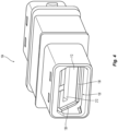
Fig. 4 is a perspective view of the adapter inFig. 1 from the front; -
Fig. 5 is an elevational view of a cross section of a portion of the fiber optic connector inFig. 1 ; -
Fig. 6 is a side elevational view of the adapter inFig. 1 ; -
Fig. 7 is a side perspective view of the shutters for the fiber optic connector and adapter inFig. 1 ; -
Fig. 8 is a side perspective view of a cross section of the shutters for the fiber optic connector and adapter inFig. 7 ; -
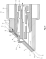
Fig. 9 is an elevational view of a cross section of a portion of the fiber optic connector and adapter inFig. 1 as they engage one another; -
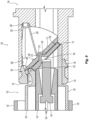
Fig. 10 is an elevational view of a cross section of a portion of the fiber optic connector and adapter inFig. 1 as the shroud and adapter engage one another; -
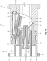
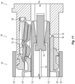
Fig. 11 is an elevational view of a cross section of a portion of the fiber optic connector and adapter inFig. 1 as the shutters have rotated out of the way; -
Fig. 12A is a side elevational view of two fiber optic connectors just before entering an adapter fromFig. 1 ; -
Fig. 12B is a side elevational view of the two fiber optic connectors in the adapter and the two shutters engaging one another; -
Fig. 12C is a side elevational view of two fiber optic connectors farther into the adapter and the shutters rotated out of the way; -
Fig. 12D is a side elevational view of two fiber optic connectors just prior to engaging guide pins to align the fiber optic connectors with the shutters completely out of the way; and -
Fig. 12E is a top elevational view of two fiber optic connectors engaging one another. - Reference will now be made in detail to the present preferred embodiment(s) of the invention, examples of which are illustrated in the accompanying drawings. Whenever possible, the same reference numerals will be used throughout the drawings to refer to the same or like parts.
- Applicant notes that the term "front" or "forward" means that direction where the fiber optic connector would meet with another fiber optic connector or device, while the term "rear" or "rearward" is used to mean the direction from which the optical fibers enter into thefiber-optic ferrule or fiber optic connector. Thus, "front" is that part of the fiber optic connector or adapter is where the shutters are located. The "rear" or "back" is the opposite side for the fiber optic connectors. In the case of the adapters, if there are two shutters, then the rear or back is the portion between the two fronts. However, the adapter may be shown as having only one entrance for a fiber optic connector and then the rear or back would be the opposite end. Applicant also notes that the term "adjacent" is used herein to mean that the two components are next to one another with no intervening objects. However, the two components may or may not be contiguous or touching one another. Thus, there may be some space between the objects and they will still be adjacent as long as no other object (excluding air and dust particles) comes between the two components.
- One embodiment of a
shutter system 100 to prevent dust from entering a fiberoptic connector 102 and anadapter 104 is illustrated in the figures. Theshutter system 100 includes a fiberoptic connector shutter 110 and anadapter shutter 112. As explained in moredetail below, the fiberoptic connector shutter 110 engages theadapter shutter 112 as thefiberoptic connector 102 is inserted into theadapter 104. The two shutters move together, preferably about a common axis, thereby locking dust and debris therebetween, which are pushed out of the way by thefiber optic connector 102 as it is inserted into theadapter 104. - The
fiber optic connector 102 includes anouter housing 120 and aninner housing 122 that contains afiber optic ferrule 124. See, e.g.Fig. 2 . Thefiber optic ferrule 124 holds theoptical fibers 126, which are secured therein. Thefiber optic connector 102 also includes ashroud 128 that is disposed between theouter housing 120 and theinner housing 122. Thefiber optic connector 102 may include other parts that are not explicitly illustrated or discussed herein. For example, there may be a spring to bias thefiber optic ferrule 124, a spring push, a crimp body, etc. - The
adapter 104 has anopening 130 at thefront end 132 to receive thefiber optic connector 102. As is known in the art, a second fiber optic connector may be inserted into theadapter 104 from an opposite end to mate with thefiber optic connector 102. Theadapter 104 may also include achamfered front portion 134 to assist in aligning thefiber optic connector 102 with theadapter 104. Thechamfered front portion 134 may be removable (usingtabs 136 to connect with the adapter 104), permanently attached, or integral with the remainder of theadapter 104. Theadapter 104 may have other structures that assist in the mating of thefiber optic connector 102 with theadapter 104. For example, there may be adapter stop surfaces 138 in theopening 130 of the adapter 104 (see, e.g.,Figs. 1 ,2 , and5 ), guide pins 140 (Fig. 2 ), and/or other alignment and stop features. - Turning now to the
shutter system 100 andfiber optic connector 102, theshroud 128 hasshroud pivot sleeves 142, preferably twoshroud pivot sleeves 142, that are spaced apart. There are also shutterpivot sleeves 144 on the fiberoptic connector shutter 110 that are also spaced apart, theshroud pivot sleeves 142 being disposed between the twoshutter pivot sleeves 144. However, it is also possible that theshutter pivot sleeves 144 are between theshroud pivot sleeves 142. Apin 146 passes throughopenings 148 of the sleeves, 142,144 and defines a first axis A of rotation for the fiberoptic connector shutter 110 on theshroud 128. Aspring element 150 is disposed around thepin 146 and engages ashroud tab 152 with one end 154 thereof and thesecond end 156 of thespring element 150 is inserted into a shutter door opening 158 (Fig. 5 ) on the fiberoptic connector shutter 110. It should be understood thatother spring elements 150 could be used and could engage theshroud 128 and the fiberoptic connector shutter 110 in other ways and still fall within the scope of the present invention. - The
shroud 128 has afront face 160 that surrounds theshroud 128. Thefront face 160 also functions as stop surface and as a fiberoptic connector shutter 110 stop surface as well. Thefront face 160 of theshroud 128 is at an angle of about 45 degrees to an axis through the fiber optic connector 102 (along the optical fibers 126) but could be disposed at other angles as well. As can be seen in Figs. I and5 , the fiberoptic connector shutter 110 rests on thefront face 160 when disengaged from theadapter 104. This arrangement provides the dust and debris elimination function for thefiber optic connector 102. Any dust or debris that falls on thefiber optic connector 102 or on the fiberoptic connector shutter 110 does not end up on the end face of thefiber optic ferrule 124. Thefront face 160 also engages the adapter stop surfaces 138 in theopening 130 when thefiber optic connector 102 is inserted into theadapter 104. See, e.g.,Fig. 2 . This will be described in more detail below. - Looking at
Figs. 3 ,5 , and9 in particular, the fiberoptic connector shutter 110 has anouter surface 170 and aninner surface 172. The majority of theouter surface 170 lies in anouter surface plane 174, while the majority of theinner surface 172 lies in aninner surface plane 176. There may be some structures that do not lie on the inner and outer surface planes 174, 176. For example, the shutter door opening 158 for thespring element 150 may provide some structure that prevents it from lying in theouter surface plane 174. While the majority of theinner surface 172 lies on theinner surface plane 176, there may also bepads 178 on theinner surface 172 that extend away from theinner surface 172. Thepads 178 are used by thefiber optic connector 102 during insertion into the adapter to rotate the fiberoptic connector shutter 110 out of the way of thefiber optic ferrule 124. - Another structure that does not lie on the inner and outer surface planes 174, 176 is a
notch 190 on the fiberoptic connector shutter 110. As noted above, thenotch 190 will engage a similar structure on theadapter shutter 112 to move in unison and to capture the dust and debris therebetween. Thenotch 190 has anouter portion 192 extending forward from theouter surface 170 and beyond theouter surface plane 174. Thenotch 190 also has a correspondinginner indentation 194 extending into the fiberoptic connector shutter 110 forward of theinner surface plane 176. Theinner indentation 194 corresponds to a front portion of thefiber optic ferrule 124. As will be realized, when thefiber optic connector 102 is inserted into theadapter 104, an upper portion of theinner housing 122 engages the fiberoptic connector shutter 110, and thepads 178 in particular and causes the fiberoptic connector shutter 110 to rotate about the first axis A. SeeFigs. 9 and10 . - Turning now to
Figs. 6 ,7 , and9 in particular, theadapter 104 and theadapter shutter 112 will be discussed. Theadapter shutter 112 has anouter surface 200 and aninner surface 202, theouter surface 200 has anouter surface plane 204 and theinner surface 202 has aninner surface plane 206. At the top of theadapter shutter 112 is generallycircular pivot 208 that is disposed in a cavity in theadapter 104 and in thechamfered front portion 134 in particular. The generallycircular pivot 208 rotates about a second axis B within theadapter 104. The generallycircular pivot 208 has a groove 208A (seeFigs. 7 and 8 ) to receiveshroud pivot sleeves 140 andshutter pivot sleeves 142 of the fiberoptic connector shutter 110. - The
adapter shutter 112 also has anotch 210 that has anindentation 212 extending from theouter surface 200 into theadapter shutter 112 rearwardly of theouter surface plane 204 and a correspondinginner projection 214 extending from theinner surface 202 rearwardly beyond theinner surface plane 206 and into theopening 130 of theadapter 104. Preferably the configuration of theindentation 212 corresponds to configuration of thenotch 190 on the fiberoptic connector shutter 110 and theouter portion 192 in particular. This allows the fiberoptic connector shutter 110 and theadapter shutter 112 to nest and capture the dust and debris between the two shutters. Although only onenotch 210 and only onenotch 190 are shown and discussed herein, it will be appreciated that there could be more than one. - The
adapter 104 also includes aspring element 220, a torsion spring is illustrated but other resilient elements could be used, that has two arms 222,224 to bias theadapter shutter 112 in a closed position. Thefirst arm 222 engages aninside surface 226 of theadapter 104, while thesecond arm 224 engages theprojection 214 on theinner surface 202 of theadapter shutter 112. There may also be aspring stop 228 extending from theinner surface 202 of theadapter shutter 112. As theadapter shutter 112 rotates into theadapter 104, thespring arm 224 rides up theinner projection 214 until it engages thespring stop 228. - The mating of the
fiber optic connector 102 with theadapter 104 and the movement of the fiberoptic connector shutter 110 and anadapter shutter 112 will be discussed with reference toFigs. 9-11 . As the fiberoptic connector shutter 110 andshroud 128 of thefiber optic connector 102 enter theopening 130 of theadapter 104, the upper portion ofinner housing 112 makes contact with the fiberoptic connector shutter 110 and thepads 178 as shown inFig. 9 . Thefiber optic ferrule 124 is disposed within theinner indentation 194. Theshroud 128 has made contact with the adapter stop surfaces 138, preventing theshroud 128 from moving forward and into theadapter 104 any farther. However,inner housing 122 in thefiber optic ferrule 124 can still move forward into theadapter 104. At this point, theshroud pivot sleeves 142 and the shutter pivotssleeves 144 have moved into the groove 208A of thecircular pivot 208, thereby aligning first axis A with second axis B. At the same time, theouter portion 192 of thenotch 190 on fiberoptic connector shutter 110 is disposed within theindentation 122 of thenotch 210 of theadapter shutter 112. The twoouter surfaces optic connector shutter 110 and theadapter shutter 112, respectively, are adjacent to one another and in close proximity. The fiberoptic connector shutter 110 and theadapter shutter 112 havespace 230 where the dust and debris are captured during the insertion and removal of thefiber optic connector 102 from theadapter 104. The fiberoptic connector shutter 110 and theadapter shutter 112 now rotate about a combined first axis A and second axis B that forms a rotation axis. It should be noted that the fiberoptic connector shutter 110 and anadapter shutter 112 could have different configurations to allow for a larger and/orsmaller space 230 therebetween. It is also envisioned that the fiberoptic connector shutter 110 and anadapter shutter 112 could have separate axes of the rotation, but the fiberoptic connector shutter 110 and anadapter shutter 112 should always move in unison with one another to prevent the dust and debris from contaminating a joining point or area of thefiber optic connectors 102. - In
Fig. 10 , thefiber optic connector 102 has been inserted farther into theadapter 104. The fiberoptic connector shutter 110 and anadapter shutter 112 continue to rotate about the rotation axis and up and out of the way of theinner housing 122 and fiberoptic ferrule 124. It should be noted that while the fiberoptic connector shutter 110 and anadapter shutter 112 are disposed on the top of thefiber optic connector 102 and theadapter 104, they can also be disposed on the bottom thereof. - The
inner housing 122 and fiberoptic ferrule 124 have been inserted past the shutters 110,112 inFig. 11 . Thefiber optic ferrule 124 can now be mated with another fiber optic ferrule or optical component in a dust and debris-free environment. - Illustrated in
Figs. 12A-12E is the progression of the insertion of thefiber optic connector 102 into the adapter 104 (or the unmating of thefiber optic connector 102 and theadapter 104 if viewed in reverse). InFig. 12A , theshroud 128 offiber optic connectors 102 approach the ends of anadapter 104. InFig. 12B , the fiberoptic connector shutters 110 and anadapter shutters 112 have engaged one another and theshrouds 128 have made contact with the adapter stop surfaces 138 in the adapter. InFig. 12C , theinner housings 122 have contacted thepads 178 on theinner surface 172 of the fiberoptic connector shutters 110. InFig. 12D , theinner housings 122 have moved past the shutters and are approaching the guide pins (or other structures in the adapter) to assist in aligning thefiber optic connectors 102.Fig. 12E shows thefiber optic connectors 102 are in a mated condition in a clean environment. - While the shutters have been illustrated as moving and rotating towards the adapter, it is also possible that the shutters rotate towards the fiber optic connector as well.
- It will be apparent to those skilled in the art that various modifications and variations can be made to the present invention without departing from the appended claims. Thus it is intended that the present invention cover the modifications and variations of this invention provided they come within the scope of the appended claims.
Claims (9)
- A fiber optic connector (102), comprising an outer housing (120), a shroud (128) disposed at the front end of the fiber optic connector,a fiber optic connector shutter (110) rotatably mounted to the shroud about a first axis (A), the fiber optic connector shutter having an outer surface (107) and an inner surface (172), the outer surface having an outer surface plane (174) and the inner surface having an inner surface plane (176); anda notch (190) in the fiber optic connector shutter, the notch having an outer portion (192) extending forward from the outer surface beyond the outer surface plane and a corresponding inner indentation (194) extending into the fiber optic connector shutter forward of the inner surface plane, anda fiber optic ferrule (124) holding optical fibers (126),wherein the fiber optic connector (102) further comprisesan inner housing (122) that contains the fiber optic ferrule (124), andthe shroud (128) is disposed between the outer housing (120) and the inner housing (122).
- The fiber optic connector according to claim 1, wherein the notch (190) is configured to receive a portion of a fiber optic ferrule (124) from the fiber optic connector (102) in the inner indentation (194).
- The fiber optic connector according to claim 1, wherein the shroud (128) has a stop surface to engage an adapter (104) stop surface (138).
- The fiber optic connector according to claim 1, wherein a portion of the inner housing engages the fiber optic connector shutter (110) to rotate the fiber optic connector shutter when the connector housing moves (120) relative to the shroud (128).
- The fiber optic connector according to claim 1, wherein the shroud (128) has pivot sleeves (142) and the fiber optic connector shutter (110) has pivot sleeves (144), the shroud pivot sleeves and the fiber optic connector shutter pivot sleeves receiving a pin (146) therethrough to rotatably attach the fiber optic connector (102) shutter to the fiber optic connector along a first axis (A).
- A system of the fiber optic connector according to claim 1 and an adapter (104), wherein the notch (190) in the fiber optic connector shutter (110) engages a portion of an adapter shutter (112) in the adapter (104) into which the fiber optic connector (102) is inserted, wherein the fiber optic connector shutter (110) and the adapter shutter (112) rotate about the same axis as the fiber optic connector (102) is inserted into the adapter (104), and wherein the fiber optic connector shutter (110) and the adapter shutter (112) are adjacent to one another and move together when the fiber optic connector (102) and adapter (104) are mated.
- The system according to claim 6, wherein the adapter shutter (112) has a groove (208A) to receive pivot sleeves (142) on the shroud and pivot sleeves (144) on the fiber optic connector shutter (110).
- The system according to claim 6, wherein the adapter shutter (112) has an adapter notch (210) configured to receive at least a portion of the notch in the fiber optic connector shutter (110).
- The system according to claim 8, wherein the adapter shutter (112) has an outer surface (170) and an inner surface (172), the outer surface has an outer surface plane (174) and the inner surface has an inner surface plane (176), and
wherein the adapter shutter notch (210) has an indentation (194) extending rearwardly from the outer surface into the adapter shutter rearwardly of the outer surface plane and a corresponding inner portion extending rearwardly from the inner surface beyond the inner surface plane and into the adapter.
Priority Applications (1)
| Application Number | Priority Date | Filing Date | Title |
|---|---|---|---|
| EP24152140.0A EP4332651A3 (en) | 2018-01-17 | 2019-01-17 | Fiber optic connector comprising shutter |
Applications Claiming Priority (2)
| Application Number | Priority Date | Filing Date | Title |
|---|---|---|---|
| US201862618193P | 2018-01-17 | 2018-01-17 | |
| PCT/US2019/013957 WO2019143786A2 (en) | 2018-01-17 | 2019-01-17 | Dual interlocking shutter system for a fiber optic connector and adapter |
Related Child Applications (2)
| Application Number | Title | Priority Date | Filing Date |
|---|---|---|---|
| EP24152140.0A Division EP4332651A3 (en) | 2018-01-17 | 2019-01-17 | Fiber optic connector comprising shutter |
| EP24152140.0A Division-Into EP4332651A3 (en) | 2018-01-17 | 2019-01-17 | Fiber optic connector comprising shutter |
Publications (3)
| Publication Number | Publication Date |
|---|---|
| EP3740797A2 EP3740797A2 (en) | 2020-11-25 |
| EP3740797A4 EP3740797A4 (en) | 2021-09-22 |
| EP3740797B1 true EP3740797B1 (en) | 2024-02-28 |
Family
ID=67301593
Family Applications (2)
| Application Number | Title | Priority Date | Filing Date |
|---|---|---|---|
| EP19741689.4A Active EP3740797B1 (en) | 2018-01-17 | 2019-01-17 | Fiber optic connector comprising shutter |
| EP24152140.0A Pending EP4332651A3 (en) | 2018-01-17 | 2019-01-17 | Fiber optic connector comprising shutter |
Family Applications After (1)
| Application Number | Title | Priority Date | Filing Date |
|---|---|---|---|
| EP24152140.0A Pending EP4332651A3 (en) | 2018-01-17 | 2019-01-17 | Fiber optic connector comprising shutter |
Country Status (4)
| Country | Link |
|---|---|
| US (3) | US11307360B2 (en) |
| EP (2) | EP3740797B1 (en) |
| CN (1) | CN111630422B (en) |
| WO (1) | WO2019143786A2 (en) |
Families Citing this family (10)
| Publication number | Priority date | Publication date | Assignee | Title |
|---|---|---|---|---|
| WO2019079326A1 (en) * | 2017-10-17 | 2019-04-25 | Commscope Technologies Llc | Shutter configuration for a fiber optic connector port with modular fiber carriers; and connection system |
| EP3740797B1 (en) * | 2018-01-17 | 2024-02-28 | US Conec, Ltd | Fiber optic connector comprising shutter |
| JP6724094B2 (en) | 2018-09-18 | 2020-07-15 | 株式会社フジクラ | Optical connector system and optical connector with shutter |
| WO2020102489A1 (en) * | 2018-11-14 | 2020-05-22 | US Conec, Ltd | Guide pin holder for guide pins in an adapter |
| WO2021021575A1 (en) | 2019-07-26 | 2021-02-04 | Commscope Technologies Llc | Fiber optic adapters convertible between different polarity types |
| MX2023002030A (en) | 2020-08-26 | 2023-03-15 | Afl Ig Llc | Adaptor and method for mating a fiber optic connector. |
| US12523821B2 (en) | 2021-04-08 | 2026-01-13 | Commscope Technologies Llc | Telecommunications connector with latch release mechanism |
| US11815723B2 (en) | 2021-10-26 | 2023-11-14 | Sumitomo Electric Industries, Ltd. | Optical connection structure, optical connector, and optical connecting method |
| TWM643064U (en) * | 2023-03-30 | 2023-06-21 | 建毅科技股份有限公司 | fiber optic adapter |
| TWM647932U (en) * | 2023-07-18 | 2023-11-01 | 連訊通信股份有限公司 | Optical fiber adapter |
Family Cites Families (19)
| Publication number | Priority date | Publication date | Assignee | Title |
|---|---|---|---|---|
| AU660859B2 (en) * | 1992-11-26 | 1995-07-06 | Diamond S.A. | Sleeve portion for an optical fibre plug connector |
| US5687268A (en) * | 1995-11-27 | 1997-11-11 | Lucent Technologies Inc. | Pivotable optical shutter for blocking emission from a lightguide adapter #5 |
| EP0800100A1 (en) | 1996-04-04 | 1997-10-08 | US Conec Ltd | Ferrule assembly for positively engaging a guide pin |
| US6039585A (en) * | 1997-03-10 | 2000-03-21 | Reynolds Industries Incorporated | Connector assembly with self activating environmental seal |
| US5883995A (en) * | 1997-05-20 | 1999-03-16 | Adc Telecommunications, Inc. | Fiber connector and adapter |
| US6142676A (en) * | 1997-05-20 | 2000-11-07 | Adc Telecommunications, Inc. | Fiber connector and adaptor |
| EP0893716A1 (en) * | 1997-07-21 | 1999-01-27 | Diamond S.A. | Receptacle in particular for an optical connector and connector for light guides |
| US6081647A (en) | 1998-01-05 | 2000-06-27 | Molex Incorporated | Fiber optic connector receptacle |
| EP1072917A1 (en) * | 1999-07-26 | 2001-01-31 | Diamond SA | Connector with protection flap for optical connection |
| DE50105690D1 (en) * | 2001-06-29 | 2005-04-28 | Diamond Sa | Socket part and plug part for an optical connector |
| SI1504296T1 (en) | 2002-05-14 | 2012-01-31 | Huber+Suhner Ag | Optical connector |
| JP4327063B2 (en) | 2004-10-26 | 2009-09-09 | 本多通信工業株式会社 | Optical connector with shutter |
| US7785018B2 (en) | 2008-08-29 | 2010-08-31 | Corning Cable Systems Llc | Fiber optic adapters with integrated shutter |
| GB2506890B (en) * | 2012-10-10 | 2017-03-22 | Fibrefab Ltd | Fibre optic adaptor |
| CN105745564B (en) | 2013-09-30 | 2017-10-24 | 慧与发展有限责任合伙企业 | Optics is blind to match somebody with somebody formula connector and adapter |
| WO2015103726A1 (en) * | 2014-01-07 | 2015-07-16 | 深圳日海通讯技术股份有限公司 | Optical fiber connector |
| TWI608261B (en) | 2016-11-29 | 2017-12-11 | 普泰光電股份有限公司 | Optical fiber adapter with shutter member |
| EP3740797B1 (en) * | 2018-01-17 | 2024-02-28 | US Conec, Ltd | Fiber optic connector comprising shutter |
| JP6724094B2 (en) | 2018-09-18 | 2020-07-15 | 株式会社フジクラ | Optical connector system and optical connector with shutter |
-
2019
- 2019-01-17 EP EP19741689.4A patent/EP3740797B1/en active Active
- 2019-01-17 CN CN201980009031.4A patent/CN111630422B/en active Active
- 2019-01-17 US US16/961,511 patent/US11307360B2/en active Active
- 2019-01-17 WO PCT/US2019/013957 patent/WO2019143786A2/en not_active Ceased
- 2019-01-17 EP EP24152140.0A patent/EP4332651A3/en active Pending
-
2022
- 2022-04-18 US US17/723,223 patent/US11822130B2/en active Active
-
2023
- 2023-11-20 US US18/514,221 patent/US12321019B2/en active Active
Also Published As
| Publication number | Publication date |
|---|---|
| EP3740797A2 (en) | 2020-11-25 |
| EP4332651A3 (en) | 2024-05-22 |
| US12321019B2 (en) | 2025-06-03 |
| US20240094473A1 (en) | 2024-03-21 |
| WO2019143786A3 (en) | 2019-08-29 |
| CN111630422A (en) | 2020-09-04 |
| US11307360B2 (en) | 2022-04-19 |
| US20200341209A1 (en) | 2020-10-29 |
| WO2019143786A2 (en) | 2019-07-25 |
| US11822130B2 (en) | 2023-11-21 |
| CN111630422B (en) | 2023-01-31 |
| EP4332651A2 (en) | 2024-03-06 |
| EP3740797A4 (en) | 2021-09-22 |
| US20220244466A1 (en) | 2022-08-04 |
Similar Documents
| Publication | Publication Date | Title |
|---|---|---|
| US12321019B2 (en) | Dual interlocking shutter system for a fiber optic connector and adapter | |
| EP1139128A2 (en) | Shielded optical connector | |
| JP7855653B2 (en) | Fiber optic connectors and fiber optic connection systems | |
| KR101607906B1 (en) | Shuttered lc adapter | |
| EP0613030B1 (en) | Optical fiber connector | |
| CN108351475B (en) | Adapter shutter with integrated connector lock | |
| US7261472B2 (en) | Ultra-small, form factor single fiber optical interconnect system, with push-push type insertion/withdrawal mechanism and shuttered modular connector and shuttered adapter and method for using same | |
| CN101105556B (en) | Optical connection part with a light shielding part and whose size can be reduced | |
| US20030147597A1 (en) | Cantilevered shutter for optical adapter | |
| US20090028507A1 (en) | Fiber optic adapter with integrated shutter | |
| US11086083B2 (en) | Optical connector with dust ingress mitigating cover | |
| US10444441B1 (en) | Pivotable housing for a fiber optic connector | |
| EP1849030A2 (en) | Ultra-small, form factor single fiber optical interconnect system, with push-push type insertion/withdrawal mechanism and shuttered modular connector and shuttered adapter and method for using same | |
| AU2009286131A1 (en) | Fiber optic adapters with integrated shutter | |
| US20210231884A1 (en) | Optical connector | |
| JP6724094B2 (en) | Optical connector system and optical connector with shutter | |
| JP5398560B2 (en) | Optical connector and assembly method thereof | |
| CN119511466A (en) | Fiber Optic Adapter | |
| CN116235092A (en) | Matching method of adapter and fiber optic connector | |
| JPH10300985A (en) | Multi-core optical connector | |
| CN223692549U (en) | Optical fiber adapter | |
| WO2025227428A1 (en) | Photoelectric composite connector | |
| CA2594549A1 (en) | Multi fiber optical interconnect system, with push-push type insertion/withdrawal mechanism, mt-type connector and shuttered adapter and method for using same |
Legal Events
| Date | Code | Title | Description |
|---|---|---|---|
| STAA | Information on the status of an ep patent application or granted ep patent |
Free format text: STATUS: THE INTERNATIONAL PUBLICATION HAS BEEN MADE |
|
| PUAI | Public reference made under article 153(3) epc to a published international application that has entered the european phase |
Free format text: ORIGINAL CODE: 0009012 |
|
| STAA | Information on the status of an ep patent application or granted ep patent |
Free format text: STATUS: REQUEST FOR EXAMINATION WAS MADE |
|
| 17P | Request for examination filed |
Effective date: 20200813 |
|
| AK | Designated contracting states |
Kind code of ref document: A2 Designated state(s): AL AT BE BG CH CY CZ DE DK EE ES FI FR GB GR HR HU IE IS IT LI LT LU LV MC MK MT NL NO PL PT RO RS SE SI SK SM TR |
|
| AX | Request for extension of the european patent |
Extension state: BA ME |
|
| DAV | Request for validation of the european patent (deleted) | ||
| DAX | Request for extension of the european patent (deleted) | ||
| REG | Reference to a national code |
Ref country code: DE Ref legal event code: R079 Free format text: PREVIOUS MAIN CLASS: G02B0006245000 Ipc: G02B0006380000 Ref country code: DE Ref legal event code: R079 Ref document number: 602019047327 Country of ref document: DE Free format text: PREVIOUS MAIN CLASS: G02B0006245000 Ipc: G02B0006380000 |
|
| A4 | Supplementary search report drawn up and despatched |
Effective date: 20210819 |
|
| RIC1 | Information provided on ipc code assigned before grant |
Ipc: G02B 6/38 20060101AFI20210813BHEP |
|
| GRAP | Despatch of communication of intention to grant a patent |
Free format text: ORIGINAL CODE: EPIDOSNIGR1 |
|
| STAA | Information on the status of an ep patent application or granted ep patent |
Free format text: STATUS: GRANT OF PATENT IS INTENDED |
|
| INTG | Intention to grant announced |
Effective date: 20230915 |
|
| GRAS | Grant fee paid |
Free format text: ORIGINAL CODE: EPIDOSNIGR3 |
|
| GRAA | (expected) grant |
Free format text: ORIGINAL CODE: 0009210 |
|
| STAA | Information on the status of an ep patent application or granted ep patent |
Free format text: STATUS: THE PATENT HAS BEEN GRANTED |
|
| P01 | Opt-out of the competence of the unified patent court (upc) registered |
Effective date: 20231222 |
|
| AK | Designated contracting states |
Kind code of ref document: B1 Designated state(s): AL AT BE BG CH CY CZ DE DK EE ES FI FR GB GR HR HU IE IS IT LI LT LU LV MC MK MT NL NO PL PT RO RS SE SI SK SM TR |
|
| REG | Reference to a national code |
Ref country code: GB Ref legal event code: FG4D |
|
| REG | Reference to a national code |
Ref country code: CH Ref legal event code: EP |
|
| REG | Reference to a national code |
Ref country code: DE Ref legal event code: R096 Ref document number: 602019047327 Country of ref document: DE |
|
| REG | Reference to a national code |
Ref country code: IE Ref legal event code: FG4D |
|
| REG | Reference to a national code |
Ref country code: SE Ref legal event code: TRGR |
|
| REG | Reference to a national code |
Ref country code: LT Ref legal event code: MG9D |
|
| REG | Reference to a national code |
Ref country code: NL Ref legal event code: FP |
|
| PG25 | Lapsed in a contracting state [announced via postgrant information from national office to epo] |
Ref country code: IS Free format text: LAPSE BECAUSE OF FAILURE TO SUBMIT A TRANSLATION OF THE DESCRIPTION OR TO PAY THE FEE WITHIN THE PRESCRIBED TIME-LIMIT Effective date: 20240628 |
|
| PG25 | Lapsed in a contracting state [announced via postgrant information from national office to epo] |
Ref country code: LT Free format text: LAPSE BECAUSE OF FAILURE TO SUBMIT A TRANSLATION OF THE DESCRIPTION OR TO PAY THE FEE WITHIN THE PRESCRIBED TIME-LIMIT Effective date: 20240228 |
|
| PG25 | Lapsed in a contracting state [announced via postgrant information from national office to epo] |
Ref country code: GR Free format text: LAPSE BECAUSE OF FAILURE TO SUBMIT A TRANSLATION OF THE DESCRIPTION OR TO PAY THE FEE WITHIN THE PRESCRIBED TIME-LIMIT Effective date: 20240529 |
|
| PG25 | Lapsed in a contracting state [announced via postgrant information from national office to epo] |
Ref country code: RS Free format text: LAPSE BECAUSE OF FAILURE TO SUBMIT A TRANSLATION OF THE DESCRIPTION OR TO PAY THE FEE WITHIN THE PRESCRIBED TIME-LIMIT Effective date: 20240528 Ref country code: HR Free format text: LAPSE BECAUSE OF FAILURE TO SUBMIT A TRANSLATION OF THE DESCRIPTION OR TO PAY THE FEE WITHIN THE PRESCRIBED TIME-LIMIT Effective date: 20240228 |
|
| PG25 | Lapsed in a contracting state [announced via postgrant information from national office to epo] |
Ref country code: ES Free format text: LAPSE BECAUSE OF FAILURE TO SUBMIT A TRANSLATION OF THE DESCRIPTION OR TO PAY THE FEE WITHIN THE PRESCRIBED TIME-LIMIT Effective date: 20240228 |
|
| PG25 | Lapsed in a contracting state [announced via postgrant information from national office to epo] |
Ref country code: RS Free format text: LAPSE BECAUSE OF FAILURE TO SUBMIT A TRANSLATION OF THE DESCRIPTION OR TO PAY THE FEE WITHIN THE PRESCRIBED TIME-LIMIT Effective date: 20240528 Ref country code: NO Free format text: LAPSE BECAUSE OF FAILURE TO SUBMIT A TRANSLATION OF THE DESCRIPTION OR TO PAY THE FEE WITHIN THE PRESCRIBED TIME-LIMIT Effective date: 20240528 Ref country code: LT Free format text: LAPSE BECAUSE OF FAILURE TO SUBMIT A TRANSLATION OF THE DESCRIPTION OR TO PAY THE FEE WITHIN THE PRESCRIBED TIME-LIMIT Effective date: 20240228 Ref country code: IS Free format text: LAPSE BECAUSE OF FAILURE TO SUBMIT A TRANSLATION OF THE DESCRIPTION OR TO PAY THE FEE WITHIN THE PRESCRIBED TIME-LIMIT Effective date: 20240628 Ref country code: HR Free format text: LAPSE BECAUSE OF FAILURE TO SUBMIT A TRANSLATION OF THE DESCRIPTION OR TO PAY THE FEE WITHIN THE PRESCRIBED TIME-LIMIT Effective date: 20240228 Ref country code: GR Free format text: LAPSE BECAUSE OF FAILURE TO SUBMIT A TRANSLATION OF THE DESCRIPTION OR TO PAY THE FEE WITHIN THE PRESCRIBED TIME-LIMIT Effective date: 20240529 Ref country code: FI Free format text: LAPSE BECAUSE OF FAILURE TO SUBMIT A TRANSLATION OF THE DESCRIPTION OR TO PAY THE FEE WITHIN THE PRESCRIBED TIME-LIMIT Effective date: 20240228 Ref country code: ES Free format text: LAPSE BECAUSE OF FAILURE TO SUBMIT A TRANSLATION OF THE DESCRIPTION OR TO PAY THE FEE WITHIN THE PRESCRIBED TIME-LIMIT Effective date: 20240228 Ref country code: BG Free format text: LAPSE BECAUSE OF FAILURE TO SUBMIT A TRANSLATION OF THE DESCRIPTION OR TO PAY THE FEE WITHIN THE PRESCRIBED TIME-LIMIT Effective date: 20240228 |
|
| PG25 | Lapsed in a contracting state [announced via postgrant information from national office to epo] |
Ref country code: PL Free format text: LAPSE BECAUSE OF FAILURE TO SUBMIT A TRANSLATION OF THE DESCRIPTION OR TO PAY THE FEE WITHIN THE PRESCRIBED TIME-LIMIT Effective date: 20240228 Ref country code: PT Free format text: LAPSE BECAUSE OF FAILURE TO SUBMIT A TRANSLATION OF THE DESCRIPTION OR TO PAY THE FEE WITHIN THE PRESCRIBED TIME-LIMIT Effective date: 20240628 |
|
| REG | Reference to a national code |
Ref country code: AT Ref legal event code: MK05 Ref document number: 1661757 Country of ref document: AT Kind code of ref document: T Effective date: 20240228 |
|
| PG25 | Lapsed in a contracting state [announced via postgrant information from national office to epo] |
Ref country code: PT Free format text: LAPSE BECAUSE OF FAILURE TO SUBMIT A TRANSLATION OF THE DESCRIPTION OR TO PAY THE FEE WITHIN THE PRESCRIBED TIME-LIMIT Effective date: 20240628 Ref country code: PL Free format text: LAPSE BECAUSE OF FAILURE TO SUBMIT A TRANSLATION OF THE DESCRIPTION OR TO PAY THE FEE WITHIN THE PRESCRIBED TIME-LIMIT Effective date: 20240228 Ref country code: LV Free format text: LAPSE BECAUSE OF FAILURE TO SUBMIT A TRANSLATION OF THE DESCRIPTION OR TO PAY THE FEE WITHIN THE PRESCRIBED TIME-LIMIT Effective date: 20240228 |
|
| PG25 | Lapsed in a contracting state [announced via postgrant information from national office to epo] |
Ref country code: DK Free format text: LAPSE BECAUSE OF FAILURE TO SUBMIT A TRANSLATION OF THE DESCRIPTION OR TO PAY THE FEE WITHIN THE PRESCRIBED TIME-LIMIT Effective date: 20240228 |
|
| PG25 | Lapsed in a contracting state [announced via postgrant information from national office to epo] |
Ref country code: SM Free format text: LAPSE BECAUSE OF FAILURE TO SUBMIT A TRANSLATION OF THE DESCRIPTION OR TO PAY THE FEE WITHIN THE PRESCRIBED TIME-LIMIT Effective date: 20240228 |
|
| PG25 | Lapsed in a contracting state [announced via postgrant information from national office to epo] |
Ref country code: EE Free format text: LAPSE BECAUSE OF FAILURE TO SUBMIT A TRANSLATION OF THE DESCRIPTION OR TO PAY THE FEE WITHIN THE PRESCRIBED TIME-LIMIT Effective date: 20240228 Ref country code: CZ Free format text: LAPSE BECAUSE OF FAILURE TO SUBMIT A TRANSLATION OF THE DESCRIPTION OR TO PAY THE FEE WITHIN THE PRESCRIBED TIME-LIMIT Effective date: 20240228 |
|
| PG25 | Lapsed in a contracting state [announced via postgrant information from national office to epo] |
Ref country code: AT Free format text: LAPSE BECAUSE OF FAILURE TO SUBMIT A TRANSLATION OF THE DESCRIPTION OR TO PAY THE FEE WITHIN THE PRESCRIBED TIME-LIMIT Effective date: 20240228 |
|
| PG25 | Lapsed in a contracting state [announced via postgrant information from national office to epo] |
Ref country code: SK Free format text: LAPSE BECAUSE OF FAILURE TO SUBMIT A TRANSLATION OF THE DESCRIPTION OR TO PAY THE FEE WITHIN THE PRESCRIBED TIME-LIMIT Effective date: 20240228 |
|
| PG25 | Lapsed in a contracting state [announced via postgrant information from national office to epo] |
Ref country code: SM Free format text: LAPSE BECAUSE OF FAILURE TO SUBMIT A TRANSLATION OF THE DESCRIPTION OR TO PAY THE FEE WITHIN THE PRESCRIBED TIME-LIMIT Effective date: 20240228 Ref country code: SK Free format text: LAPSE BECAUSE OF FAILURE TO SUBMIT A TRANSLATION OF THE DESCRIPTION OR TO PAY THE FEE WITHIN THE PRESCRIBED TIME-LIMIT Effective date: 20240228 Ref country code: RO Free format text: LAPSE BECAUSE OF FAILURE TO SUBMIT A TRANSLATION OF THE DESCRIPTION OR TO PAY THE FEE WITHIN THE PRESCRIBED TIME-LIMIT Effective date: 20240228 Ref country code: EE Free format text: LAPSE BECAUSE OF FAILURE TO SUBMIT A TRANSLATION OF THE DESCRIPTION OR TO PAY THE FEE WITHIN THE PRESCRIBED TIME-LIMIT Effective date: 20240228 Ref country code: DK Free format text: LAPSE BECAUSE OF FAILURE TO SUBMIT A TRANSLATION OF THE DESCRIPTION OR TO PAY THE FEE WITHIN THE PRESCRIBED TIME-LIMIT Effective date: 20240228 Ref country code: CZ Free format text: LAPSE BECAUSE OF FAILURE TO SUBMIT A TRANSLATION OF THE DESCRIPTION OR TO PAY THE FEE WITHIN THE PRESCRIBED TIME-LIMIT Effective date: 20240228 Ref country code: AT Free format text: LAPSE BECAUSE OF FAILURE TO SUBMIT A TRANSLATION OF THE DESCRIPTION OR TO PAY THE FEE WITHIN THE PRESCRIBED TIME-LIMIT Effective date: 20240228 |
|
| REG | Reference to a national code |
Ref country code: DE Ref legal event code: R097 Ref document number: 602019047327 Country of ref document: DE |
|
| PG25 | Lapsed in a contracting state [announced via postgrant information from national office to epo] |
Ref country code: IT Free format text: LAPSE BECAUSE OF FAILURE TO SUBMIT A TRANSLATION OF THE DESCRIPTION OR TO PAY THE FEE WITHIN THE PRESCRIBED TIME-LIMIT Effective date: 20240228 |
|
| PG25 | Lapsed in a contracting state [announced via postgrant information from national office to epo] |
Ref country code: IT Free format text: LAPSE BECAUSE OF FAILURE TO SUBMIT A TRANSLATION OF THE DESCRIPTION OR TO PAY THE FEE WITHIN THE PRESCRIBED TIME-LIMIT Effective date: 20240228 |
|
| PLBE | No opposition filed within time limit |
Free format text: ORIGINAL CODE: 0009261 |
|
| STAA | Information on the status of an ep patent application or granted ep patent |
Free format text: STATUS: NO OPPOSITION FILED WITHIN TIME LIMIT |
|
| 26N | No opposition filed |
Effective date: 20241129 |
|
| PG25 | Lapsed in a contracting state [announced via postgrant information from national office to epo] |
Ref country code: SI Free format text: LAPSE BECAUSE OF FAILURE TO SUBMIT A TRANSLATION OF THE DESCRIPTION OR TO PAY THE FEE WITHIN THE PRESCRIBED TIME-LIMIT Effective date: 20240228 |
|
| PG25 | Lapsed in a contracting state [announced via postgrant information from national office to epo] |
Ref country code: MC Free format text: LAPSE BECAUSE OF FAILURE TO SUBMIT A TRANSLATION OF THE DESCRIPTION OR TO PAY THE FEE WITHIN THE PRESCRIBED TIME-LIMIT Effective date: 20240228 Ref country code: LU Free format text: LAPSE BECAUSE OF NON-PAYMENT OF DUE FEES Effective date: 20250117 |
|
| PG25 | Lapsed in a contracting state [announced via postgrant information from national office to epo] |
Ref country code: BE Free format text: LAPSE BECAUSE OF NON-PAYMENT OF DUE FEES Effective date: 20250131 |
|
| REG | Reference to a national code |
Ref country code: BE Ref legal event code: MM Effective date: 20250131 |
|
| PG25 | Lapsed in a contracting state [announced via postgrant information from national office to epo] |
Ref country code: IE Free format text: LAPSE BECAUSE OF NON-PAYMENT OF DUE FEES Effective date: 20250117 |
|
| REG | Reference to a national code |
Ref country code: CH Ref legal event code: U11 Free format text: ST27 STATUS EVENT CODE: U-0-0-U10-U11 (AS PROVIDED BY THE NATIONAL OFFICE) Effective date: 20260201 |
|
| PGFP | Annual fee paid to national office [announced via postgrant information from national office to epo] |
Ref country code: NL Payment date: 20260126 Year of fee payment: 8 |
|
| PGFP | Annual fee paid to national office [announced via postgrant information from national office to epo] |
Ref country code: SE Payment date: 20260127 Year of fee payment: 8 |
|
| PGFP | Annual fee paid to national office [announced via postgrant information from national office to epo] |
Ref country code: GB Payment date: 20260127 Year of fee payment: 8 |
|
| PGFP | Annual fee paid to national office [announced via postgrant information from national office to epo] |
Ref country code: DE Payment date: 20260128 Year of fee payment: 8 |
|
| PGFP | Annual fee paid to national office [announced via postgrant information from national office to epo] |
Ref country code: FR Payment date: 20260126 Year of fee payment: 8 |
|
| PGFP | Annual fee paid to national office [announced via postgrant information from national office to epo] |
Ref country code: CH Payment date: 20260201 Year of fee payment: 8 |
|
| PG25 | Lapsed in a contracting state [announced via postgrant information from national office to epo] |
Ref country code: CY Free format text: LAPSE BECAUSE OF FAILURE TO SUBMIT A TRANSLATION OF THE DESCRIPTION OR TO PAY THE FEE WITHIN THE PRESCRIBED TIME-LIMIT Effective date: 20240228 |
|
| PG25 | Lapsed in a contracting state [announced via postgrant information from national office to epo] |
Ref country code: TR Free format text: LAPSE BECAUSE OF FAILURE TO SUBMIT A TRANSLATION OF THE DESCRIPTION OR TO PAY THE FEE WITHIN THE PRESCRIBED TIME-LIMIT Effective date: 20240228 |