EP3740426B1 - Shock absorber configured with a deformable energy absorbing member - Google Patents
Shock absorber configured with a deformable energy absorbing member Download PDFInfo
- Publication number
- EP3740426B1 EP3740426B1 EP19741293.5A EP19741293A EP3740426B1 EP 3740426 B1 EP3740426 B1 EP 3740426B1 EP 19741293 A EP19741293 A EP 19741293A EP 3740426 B1 EP3740426 B1 EP 3740426B1
- Authority
- EP
- European Patent Office
- Prior art keywords
- aircraft
- primary piston
- main body
- shock absorber
- pressure
- Prior art date
- Legal status (The legal status is an assumption and is not a legal conclusion. Google has not performed a legal analysis and makes no representation as to the accuracy of the status listed.)
- Active
Links
Images



Classifications
-
- E—FIXED CONSTRUCTIONS
- E05—LOCKS; KEYS; WINDOW OR DOOR FITTINGS; SAFES
- E05F—DEVICES FOR MOVING WINGS INTO OPEN OR CLOSED POSITION; CHECKS FOR WINGS; WING FITTINGS NOT OTHERWISE PROVIDED FOR, CONCERNED WITH THE FUNCTIONING OF THE WING
- E05F5/00—Braking devices, e.g. checks; Stops; Buffers
- E05F5/06—Buffers or stops limiting opening of swinging wings, e.g. floor or wall stops
-
- B—PERFORMING OPERATIONS; TRANSPORTING
- B64—AIRCRAFT; AVIATION; COSMONAUTICS
- B64C—AEROPLANES; HELICOPTERS
- B64C1/00—Fuselages; Constructional features common to fuselages, wings, stabilising surfaces or the like
- B64C1/14—Windows; Doors; Hatch covers or access panels; Surrounding frame structures; Canopies; Windscreens accessories therefor, e.g. pressure sensors, water deflectors, hinges, seals, handles, latches, windscreen wipers
- B64C1/1407—Doors; surrounding frames
- B64C1/1469—Doors between cockpit and cabin
-
- B—PERFORMING OPERATIONS; TRANSPORTING
- B64—AIRCRAFT; AVIATION; COSMONAUTICS
- B64D—EQUIPMENT FOR FITTING IN OR TO AIRCRAFT; FLIGHT SUITS; PARACHUTES; ARRANGEMENT OR MOUNTING OF POWER PLANTS OR PROPULSION TRANSMISSIONS IN AIRCRAFT
- B64D45/00—Aircraft indicators or protectors not otherwise provided for
-
- E—FIXED CONSTRUCTIONS
- E05—LOCKS; KEYS; WINDOW OR DOOR FITTINGS; SAFES
- E05B—LOCKS; ACCESSORIES THEREFOR; HANDCUFFS
- E05B77/00—Vehicle locks characterised by special functions or purposes
- E05B77/54—Automatic securing or unlocking of bolts triggered by certain vehicle parameters, e.g. exceeding a speed threshold
-
- E—FIXED CONSTRUCTIONS
- E05—LOCKS; KEYS; WINDOW OR DOOR FITTINGS; SAFES
- E05B—LOCKS; ACCESSORIES THEREFOR; HANDCUFFS
- E05B81/00—Power-actuated vehicle locks
- E05B81/54—Electrical circuits
- E05B81/56—Control of actuators
-
- E—FIXED CONSTRUCTIONS
- E05—LOCKS; KEYS; WINDOW OR DOOR FITTINGS; SAFES
- E05F—DEVICES FOR MOVING WINGS INTO OPEN OR CLOSED POSITION; CHECKS FOR WINGS; WING FITTINGS NOT OTHERWISE PROVIDED FOR, CONCERNED WITH THE FUNCTIONING OF THE WING
- E05F3/00—Closers or openers with braking devices, e.g. checks; Construction of pneumatic or liquid braking devices
- E05F3/04—Closers or openers with braking devices, e.g. checks; Construction of pneumatic or liquid braking devices with liquid piston brakes
-
- E—FIXED CONSTRUCTIONS
- E05—LOCKS; KEYS; WINDOW OR DOOR FITTINGS; SAFES
- E05F—DEVICES FOR MOVING WINGS INTO OPEN OR CLOSED POSITION; CHECKS FOR WINGS; WING FITTINGS NOT OTHERWISE PROVIDED FOR, CONCERNED WITH THE FUNCTIONING OF THE WING
- E05F5/00—Braking devices, e.g. checks; Stops; Buffers
- E05F5/06—Buffers or stops limiting opening of swinging wings, e.g. floor or wall stops
- E05F5/10—Buffers or stops limiting opening of swinging wings, e.g. floor or wall stops with piston brakes
-
- F—MECHANICAL ENGINEERING; LIGHTING; HEATING; WEAPONS; BLASTING
- F16—ENGINEERING ELEMENTS AND UNITS; GENERAL MEASURES FOR PRODUCING AND MAINTAINING EFFECTIVE FUNCTIONING OF MACHINES OR INSTALLATIONS; THERMAL INSULATION IN GENERAL
- F16F—SPRINGS; SHOCK-ABSORBERS; MEANS FOR DAMPING VIBRATION
- F16F7/00—Vibration-dampers; Shock-absorbers
- F16F7/12—Vibration-dampers; Shock-absorbers using plastic deformation of members
- F16F7/121—Vibration-dampers; Shock-absorbers using plastic deformation of members the members having a cellular, e.g. honeycomb, structure
-
- F—MECHANICAL ENGINEERING; LIGHTING; HEATING; WEAPONS; BLASTING
- F16—ENGINEERING ELEMENTS AND UNITS; GENERAL MEASURES FOR PRODUCING AND MAINTAINING EFFECTIVE FUNCTIONING OF MACHINES OR INSTALLATIONS; THERMAL INSULATION IN GENERAL
- F16F—SPRINGS; SHOCK-ABSORBERS; MEANS FOR DAMPING VIBRATION
- F16F7/00—Vibration-dampers; Shock-absorbers
- F16F7/12—Vibration-dampers; Shock-absorbers using plastic deformation of members
- F16F7/125—Units with a telescopic-like action as one member moves into, or out of a second member
-
- F—MECHANICAL ENGINEERING; LIGHTING; HEATING; WEAPONS; BLASTING
- F16—ENGINEERING ELEMENTS AND UNITS; GENERAL MEASURES FOR PRODUCING AND MAINTAINING EFFECTIVE FUNCTIONING OF MACHINES OR INSTALLATIONS; THERMAL INSULATION IN GENERAL
- F16F—SPRINGS; SHOCK-ABSORBERS; MEANS FOR DAMPING VIBRATION
- F16F9/00—Springs, vibration-dampers, shock-absorbers, or similarly-constructed movement-dampers using a fluid or the equivalent as damping medium
- F16F9/003—Dampers characterised by having pressure absorbing means other than gas, e.g. sponge rubber
-
- F—MECHANICAL ENGINEERING; LIGHTING; HEATING; WEAPONS; BLASTING
- F16—ENGINEERING ELEMENTS AND UNITS; GENERAL MEASURES FOR PRODUCING AND MAINTAINING EFFECTIVE FUNCTIONING OF MACHINES OR INSTALLATIONS; THERMAL INSULATION IN GENERAL
- F16F—SPRINGS; SHOCK-ABSORBERS; MEANS FOR DAMPING VIBRATION
- F16F9/00—Springs, vibration-dampers, shock-absorbers, or similarly-constructed movement-dampers using a fluid or the equivalent as damping medium
- F16F9/02—Springs, vibration-dampers, shock-absorbers, or similarly-constructed movement-dampers using a fluid or the equivalent as damping medium using gas only or vacuum
- F16F9/0209—Telescopic
- F16F9/0218—Mono-tubular units
-
- F—MECHANICAL ENGINEERING; LIGHTING; HEATING; WEAPONS; BLASTING
- F16—ENGINEERING ELEMENTS AND UNITS; GENERAL MEASURES FOR PRODUCING AND MAINTAINING EFFECTIVE FUNCTIONING OF MACHINES OR INSTALLATIONS; THERMAL INSULATION IN GENERAL
- F16F—SPRINGS; SHOCK-ABSORBERS; MEANS FOR DAMPING VIBRATION
- F16F9/00—Springs, vibration-dampers, shock-absorbers, or similarly-constructed movement-dampers using a fluid or the equivalent as damping medium
- F16F9/10—Springs, vibration-dampers, shock-absorbers, or similarly-constructed movement-dampers using a fluid or the equivalent as damping medium using liquid only; using a fluid of which the nature is immaterial
- F16F9/14—Devices with one or more members, e.g. pistons, vanes, moving to and fro in chambers and using throttling effect
- F16F9/16—Devices with one or more members, e.g. pistons, vanes, moving to and fro in chambers and using throttling effect involving only straight-line movement of the effective parts
- F16F9/18—Devices with one or more members, e.g. pistons, vanes, moving to and fro in chambers and using throttling effect involving only straight-line movement of the effective parts with a closed cylinder and a piston separating two or more working spaces therein
- F16F9/19—Devices with one or more members, e.g. pistons, vanes, moving to and fro in chambers and using throttling effect involving only straight-line movement of the effective parts with a closed cylinder and a piston separating two or more working spaces therein with a single cylinder and of single-tube type
-
- F—MECHANICAL ENGINEERING; LIGHTING; HEATING; WEAPONS; BLASTING
- F16—ENGINEERING ELEMENTS AND UNITS; GENERAL MEASURES FOR PRODUCING AND MAINTAINING EFFECTIVE FUNCTIONING OF MACHINES OR INSTALLATIONS; THERMAL INSULATION IN GENERAL
- F16F—SPRINGS; SHOCK-ABSORBERS; MEANS FOR DAMPING VIBRATION
- F16F9/00—Springs, vibration-dampers, shock-absorbers, or similarly-constructed movement-dampers using a fluid or the equivalent as damping medium
- F16F9/32—Details
- F16F9/48—Arrangements for providing different damping effects at different parts of the stroke
-
- B—PERFORMING OPERATIONS; TRANSPORTING
- B64—AIRCRAFT; AVIATION; COSMONAUTICS
- B64C—AEROPLANES; HELICOPTERS
- B64C1/00—Fuselages; Constructional features common to fuselages, wings, stabilising surfaces or the like
- B64C2001/009—Fuselages; Constructional features common to fuselages, wings, stabilising surfaces or the like comprising decompression panels or valves for pressure equalisation in fuselages or floors
-
- E—FIXED CONSTRUCTIONS
- E05—LOCKS; KEYS; WINDOW OR DOOR FITTINGS; SAFES
- E05Y—INDEXING SCHEME ASSOCIATED WITH SUBCLASSES E05D AND E05F, RELATING TO CONSTRUCTION ELEMENTS, ELECTRIC CONTROL, POWER SUPPLY, POWER SIGNAL OR TRANSMISSION, USER INTERFACES, MOUNTING OR COUPLING, DETAILS, ACCESSORIES, AUXILIARY OPERATIONS NOT OTHERWISE PROVIDED FOR, APPLICATION THEREOF
- E05Y2201/00—Constructional elements; Accessories therefor
- E05Y2201/20—Brakes; Disengaging means; Holders; Stops; Valves; Accessories therefor
- E05Y2201/21—Brakes
- E05Y2201/212—Buffers
-
- E—FIXED CONSTRUCTIONS
- E05—LOCKS; KEYS; WINDOW OR DOOR FITTINGS; SAFES
- E05Y—INDEXING SCHEME ASSOCIATED WITH SUBCLASSES E05D AND E05F, RELATING TO CONSTRUCTION ELEMENTS, ELECTRIC CONTROL, POWER SUPPLY, POWER SIGNAL OR TRANSMISSION, USER INTERFACES, MOUNTING OR COUPLING, DETAILS, ACCESSORIES, AUXILIARY OPERATIONS NOT OTHERWISE PROVIDED FOR, APPLICATION THEREOF
- E05Y2900/00—Application of doors, windows, wings or fittings thereof
- E05Y2900/50—Application of doors, windows, wings or fittings thereof for vehicles
- E05Y2900/502—Application of doors, windows, wings or fittings thereof for vehicles for aircraft or spacecraft
-
- E—FIXED CONSTRUCTIONS
- E05—LOCKS; KEYS; WINDOW OR DOOR FITTINGS; SAFES
- E05Y—INDEXING SCHEME ASSOCIATED WITH SUBCLASSES E05D AND E05F, RELATING TO CONSTRUCTION ELEMENTS, ELECTRIC CONTROL, POWER SUPPLY, POWER SIGNAL OR TRANSMISSION, USER INTERFACES, MOUNTING OR COUPLING, DETAILS, ACCESSORIES, AUXILIARY OPERATIONS NOT OTHERWISE PROVIDED FOR, APPLICATION THEREOF
- E05Y2900/00—Application of doors, windows, wings or fittings thereof
- E05Y2900/50—Application of doors, windows, wings or fittings thereof for vehicles
- E05Y2900/53—Type of wing
- E05Y2900/531—Doors
-
- F—MECHANICAL ENGINEERING; LIGHTING; HEATING; WEAPONS; BLASTING
- F16—ENGINEERING ELEMENTS AND UNITS; GENERAL MEASURES FOR PRODUCING AND MAINTAINING EFFECTIVE FUNCTIONING OF MACHINES OR INSTALLATIONS; THERMAL INSULATION IN GENERAL
- F16F—SPRINGS; SHOCK-ABSORBERS; MEANS FOR DAMPING VIBRATION
- F16F2228/00—Functional characteristics, e.g. variability, frequency-dependence
- F16F2228/06—Stiffness
- F16F2228/066—Variable stiffness
-
- F—MECHANICAL ENGINEERING; LIGHTING; HEATING; WEAPONS; BLASTING
- F16—ENGINEERING ELEMENTS AND UNITS; GENERAL MEASURES FOR PRODUCING AND MAINTAINING EFFECTIVE FUNCTIONING OF MACHINES OR INSTALLATIONS; THERMAL INSULATION IN GENERAL
- F16F—SPRINGS; SHOCK-ABSORBERS; MEANS FOR DAMPING VIBRATION
- F16F2236/00—Mode of stressing of basic spring or damper elements or devices incorporating such elements
- F16F2236/04—Compression
-
- F—MECHANICAL ENGINEERING; LIGHTING; HEATING; WEAPONS; BLASTING
- F16—ENGINEERING ELEMENTS AND UNITS; GENERAL MEASURES FOR PRODUCING AND MAINTAINING EFFECTIVE FUNCTIONING OF MACHINES OR INSTALLATIONS; THERMAL INSULATION IN GENERAL
- F16F—SPRINGS; SHOCK-ABSORBERS; MEANS FOR DAMPING VIBRATION
- F16F9/00—Springs, vibration-dampers, shock-absorbers, or similarly-constructed movement-dampers using a fluid or the equivalent as damping medium
- F16F9/10—Springs, vibration-dampers, shock-absorbers, or similarly-constructed movement-dampers using a fluid or the equivalent as damping medium using liquid only; using a fluid of which the nature is immaterial
- F16F9/14—Devices with one or more members, e.g. pistons, vanes, moving to and fro in chambers and using throttling effect
- F16F9/16—Devices with one or more members, e.g. pistons, vanes, moving to and fro in chambers and using throttling effect involving only straight-line movement of the effective parts
- F16F9/165—Devices with one or more members, e.g. pistons, vanes, moving to and fro in chambers and using throttling effect involving only straight-line movement of the effective parts with two or more cylinders in line, i.e. in series connection
-
- F—MECHANICAL ENGINEERING; LIGHTING; HEATING; WEAPONS; BLASTING
- F16—ENGINEERING ELEMENTS AND UNITS; GENERAL MEASURES FOR PRODUCING AND MAINTAINING EFFECTIVE FUNCTIONING OF MACHINES OR INSTALLATIONS; THERMAL INSULATION IN GENERAL
- F16F—SPRINGS; SHOCK-ABSORBERS; MEANS FOR DAMPING VIBRATION
- F16F9/00—Springs, vibration-dampers, shock-absorbers, or similarly-constructed movement-dampers using a fluid or the equivalent as damping medium
- F16F9/30—Springs, vibration-dampers, shock-absorbers, or similarly-constructed movement-dampers using a fluid or the equivalent as damping medium with solid or semi-solid material, e.g. pasty masses, as damping medium
- F16F9/303—Springs, vibration-dampers, shock-absorbers, or similarly-constructed movement-dampers using a fluid or the equivalent as damping medium with solid or semi-solid material, e.g. pasty masses, as damping medium the damper being of the telescopic type
Definitions
- One aspect the disclosure relates to a cockpit door shock absorber configured with a deformable energy absorbing member. More specifically, one aspect of the disclosure relates to a cockpit door shock absorber configured for operation during decompression events.
- a shock absorber is typically a mechanical or hydraulic device designed to absorb and damp shock impulses. The shock absorber does this by converting the kinetic energy of the shock into another form of energy. This energy may typically be in the form of heat. Subsequently, the energy is then dissipated. Most shock absorbers are a form of dashpot (a damper which resists motion via viscous friction).
- a typical shock absorber has a limited operational envelope and cannot shock impulses or forces at extreme ends of an operational envelope needed in some specific applications. Failure to provide shock absorption in the specific applications that may be subject to an extreme range of forces may result in damage to the application to which the shock absorber is implemented or injury to individuals proximate to the application.
- shock absorber that provides an extreme range of shock absorption to an application to limit damage and injury.
- Aircraft are generally equipped with at least one cockpit door.
- the aircraft often has a separating partition that includes the at least one cockpit door that is located between a pilot, copilot, and/or flight crew (hereinafter referred to as "pilot") and passengers.
- the cockpit door provides security and privacy to the cockpit for the pilot.
- the term "cockpit” refers to a location of the aircraft where the pilot is located during operation of the aircraft.
- the cockpit may also be known as the "flight deck.” This is distinguished from the cabin, which refers to a portion of the aircraft where passengers are typically located.
- the ambient air pressure in the cockpit be generally the same as the ambient air pressure in the passenger cabin of the aircraft.
- a dangerous situation may arise if there is a sufficiently great pressure difference between opposite sides of the cockpit door or any compartments separated by the partition within the aircraft.
- One cause of a pressure difference may be a loss of cockpit pressurization.
- Loss of cockpit pressurization is a potentially serious emergency in an aircraft flying at normal cruising altitude.
- Loss of cockpit pressure, or depressurization is typically classified as explosive, rapid, or gradual, based on the time interval over which cockpit pressure is lost.
- a pressure difference caused by a loss of pressurization, depressurization, or decompression (hereinafter generally referred to as decompression) can cause structural deformation, structural damage, and possibly lead to the loss of the aircraft.
- the cockpit door may be locked or unlocked by operation of a door latch.
- the door latch may be a fully mechanical component, an electromechanical component, or the like.
- the cockpit door may be opened by automatic operation of the door latch in response to a decompression event to limit damage.
- the cockpit door once automatically unlocked can be subjected to a great deal of force due to the pressure differential.
- This pressure differential and/or force results in the door opening at a very high rotational velocity about the associated hinges that results in possible structural deformation and/or structural damage to the door as well as the cockpit and other portions of the aircraft.
- this scenario could also result in possible debris and flying parts within the cockpit that may damage critical aircraft controls and/or injure the pilot that could possibly lead to the loss of the aircraft.
- DE202012100619U discloses a hydro-pneumatic adjustment element, which has a fluid-filled cylinder with an extendable piston rod and a piston, characterized in that the adjustment element has a crash element which in the event of an overload absorbs external forces and protects the other components of the adjusting element, in particular the piston rod.
- DE3836724 presents a deflection-type absorber for the fastening, in a yielding fashion, of a bumper to the frame side member of a vehicle body has a regenerating hydraulic, gas or solid shock absorber and a non-regenerating deformation element, which is arranged downstream of the latter, to take up energy.
- the deformation element and the operating cylinder of the shock absorber are arranged in a casing which is fastened to the frame side member.
- the casing takes the form of a guiding container which tightly encloses the operating cylinder and the deformation element takes the form of an energy absorber which fills the guiding container, while resting against the container floor, in the container section situated immediately in front of the container floor.
- the deformation element takes the form of an energy absorber which fills the guiding container, while resting against the container floor, in the container section situated immediately in front of the container floor.
- an aircraft system comprising a combination of an aircraft cockpit door pivotally mounted within a partition for separating an aircraft cockpit from an aircraft passenger cabin and a shock absorber fastened thereto as defined in the appended independent claim 1, and a process of implementing an aircraft system comprising an aircraft cockpit door pivotally mounted within a partition for separating an aircraft cockpit from an aircraft passenger cabin and a shock absorber, as defined in the appended independent claim 10.
- Preferred embodiments are defined in the dependent claims.
- aspects of the disclosure are directed to an aircraft system comprising an aircraft cockpit door pivotally mounted within a partition for separating an aircraft cockpit from an aircraft passenger cabin and a shock absorber with a crushable or deformable energy absorber or dissipater member.
- a shock absorber with two added members that is designed to crush if the force or energy applied to the shock absorber exceeds a set limit.
- the primary piston is moved very fast and a fluid cannot exit an orifice fast enough, the fluid is compressed and its pressure is increased, which causes the secondary piston to move and start crushing the crushable member. This functionality thus dissipating or absorbing the energy by deforming the crushable member permanently or temporarily.
- the shock absorber is designed to transmit the energy in a direct or indirect manner to the crushable member.
- the disclosure sets forth at least two different aspects, but other geometries are possible to direct the energy that needs to be dissipated to the deformable member.
- a shock absorber including: a first end configured to be mechanically fastened to a first component.
- the shock absorber also includes a second end configured to be mechanically fastened to a second component.
- the shock absorber also includes a main body that is attached to the first end.
- the shock absorber also includes a main shaft that is attached to the second end.
- the shock absorber also includes a primary piston configured to be received in the main body.
- the shock absorber also includes the primary piston being attached to the main shaft and the primary piston being further configured to be movable with the main shaft.
- the shock absorber also includes the primary piston configured to move within the main body and further configured to provide a first damping force by movement of a fluid through the primary piston while the main shaft moves a first distance.
- the shock absorber also includes a deformable solid material arranged in the main body.
- the shock absorber also includes the primary piston configured to further move within the main body and further configured to provide a second damping force by deforming the deformable solid material after the main shaft moves the first distance.
- the shock absorber also includes where one of the first component and the second component includes a fixed structure.
- the shock absorber also includes where another one of the first component and the second component includes a movable structure.
- One aspect includes a process of implementing an aircraft system comprising an aircraft cockpit door pivotally mounted within a partition for separating an aircraft cockpit from an aircraft passenger cabin and a shock absorber, including: configuring a first end to be mechanically fastened to a first component.
- the process of implementing also includes configuring a second end to be mechanically fastened to a second component.
- the process of implementing also includes configuring a main body to be attached to the first end.
- the process of implementing also includes configuring a main shaft to be attached to the second end.
- the process of implementing also includes configuring a primary piston to be received in the main body.
- the process of implementing also includes configuring the primary piston to be attached to the main shaft and the primary piston being further configured to be movable with the main shaft.
- the process of implementing also includes configuring the primary piston to move within the main body to provide a first damping force by movement of a fluid through the primary piston while the main shaft moves a first distance.
- the process of implementing also includes configuring a deformable solid material in the main body.
- the process of implementing also includes configuring the primary piston to further move within the main body to provide a second damping force by deforming the deformable solid material after the main shaft moves the first distance.
- the process of implementing also includes where one of the first component and the second component includes a fixed structure.
- the process of implementing also includes where another one of the first component and the second component includes a movable structure.
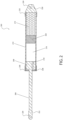
- Figure 1 is a diagram of a shock absorber belonging to an aircraft system in accordance with an aspect of the disclosure
- Figure 2 is a diagram of a shock absorber belonging to an aircraft system in accordance with another aspect of the disclosure.
- Figures 1 and 2 illustrate a cross-sectional view of a shock absorber 200.
- the shock absorber 200 may include a first end 220 and a second end 222.
- the first end 220 may be configured as a clevis having a fastener reception portion 224 that may be configured to be mechanically fastened to another structure.
- the second end 222 may be configured as a clevis having a fastener reception portion 226 that may be configured to may be mechanically fastened to another structure.
- the first end 220 is mechanically fastened to a first attachment 202 that is mechanically fastened to a cockpit door 30.
- the first end 220 is be mechanically fastened to the cockpit door 30.
- the first end 220 may be mechanically fastened to the cockpit door 30 through other intervening structures.
- the first end 220 may be mechanically fastened to the second attachment 204, which is mechanically fastened to the door post, the door frame, a wall, a divider, a bulkhead, the partition 20, or the like (hereinafter the partition 20).
- the first end 220 may be mechanically fastened directly to a partition 20.
- the first end 220 may be mechanically fastened to the partition 20 through other intervening structures.
- the second end 222 is mechanically fastened directly and/or indirectly to a fixed or movable structure.
- the second end 222 may be mechanically fastened to the first attachment 202 that may be mechanically fastened to the cockpit door 30. In one aspect, the second end 222 may be mechanically fastened to the cockpit door 30. In one aspect, the second end 222 may be mechanically fastened to the cockpit door 30 through other intervening structures. In one aspect, the second end 222 may be mechanically fastened to the second attachment 204, which be mechanically fastened to a door post, a door frame, a wall, a divider, a bulkhead, the partition 20, or the like (hereinafter the partition 20). In one aspect, the second end 222 may be mechanically fastened directly to the partition 20. In one aspect, the second end 222 may be mechanically fastened to the partition 20 through other intervening structures.
- the shock absorber 200 includes a main body 214 that is directly or indirectly connected to the first end 220.
- the main body 214 may have a cylindrical, square, polygonal or other shape cross section.
- the main body 214 may be made from a metallic material, a synthetic material, or the like.
- the main body 214 may be integral with the first end 220.
- the main body 214 may be mechanically fastened to the first end 220 through an attachment portion 232.
- the shock absorber 200 includes a main shaft 206.
- the main shaft 206 may have a cylindrical, square, polygonal or other shape cross section.
- the main shaft 206 may be made from a metallic material, a synthetic material, or the like.
- the main shaft 206 may be integral with the second end 222.
- the main shaft 206 may be mechanically fastened to the second end 222.
- the main shaft 206 may be partially located in the main body 214 and may be partially located extending from the main body 214. In one aspect, the main shaft 206 may extend through an end cap 230 that is mechanically fastened or integral with the main body 214.
- the shock absorber 200 includes a primary piston 208.
- the primary piston 208 may have a cylindrical, square, polygonal or other shape cross section.
- the primary piston 208 may be made from a metallic material, a synthetic material, or the like.
- the primary piston 208 may be integral with the main shaft 206.
- the primary piston 208 may be mechanically fastened to the main shaft 206.
- the primary piston 208 is located within the main body 214.
- the main body 214 may further be configured to include a partially closed portion defining a first fluid volume 216 and may be further configured to include a partially closed portion defining a second fluid volume 228.
- the first fluid volume 216 and the second fluid volume 228 may be configured to contain a fluid.
- the fluid may be a liquid such as an oil, hydraulic oil, a gas such as nitrogen, or the like.
- the primary piston 208 may be configured with an orifice 218 extending along a longitudinal length of the primary piston 208.
- the primary piston 208 may be positioned in the main body 214 between the first fluid volume 216 and the second fluid volume 228.
- the orifice 218 may fluidly connect the first fluid volume 216 and the second fluid volume 228.
- the distance between the first end 220 and the second end 222 may vary by movement of the main shaft 206 and the primary piston 208 into the main body 214.
- the main shaft 206 may be forced into the main body 214 and move the primary piston 208 toward the first end 220.
- the main shaft 206 will be forced into the main body 214 and move the primary piston 208 toward the first end 220.
- the primary piston 208 will reduce the volume of the first fluid volume 216 and the fluid in the first fluid volume 216 may travel through the orifice 218 into the second fluid volume 228. Accordingly, the volume of the second fluid volume 228 will increase.
- the main shaft 206 will be retracted from the main body 214 and move the primary piston 208 away from the first end 220.
- the main shaft 206 will be retracted from the main body 214 and move the primary piston 208 away from the first end 220.
- the primary piston 208 will decrease the volume of the second fluid volume 228 and the fluid in the second fluid volume 228 may travel through the orifice 218 into the first fluid volume 216. Accordingly, the volume of the first fluid volume 216 will increase.
- the above-noted operation during the first operational mode provides a damped movement of the movable structure or the cockpit door 30 by operation of the movement of the fluid between the first fluid volume 216 and the second fluid volume 228 through the orifice 218. Accordingly, movement of the movable structure or the cockpit door 30 may be slowed during the first operational mode. Moreover, the movement of the movable structure or the cockpit door 30 may be limited by the size of the first fluid volume 216 and the second fluid volume 228.
- movement of the primary piston 208 decreases a volume of the first fluid volume 216 or the second fluid volume 228 to zero, near zero, or the pressure of the fluid exceeds a set value, movement of the movable structure or the cockpit door 30 may be impeded with the exception of the second operational mode described in further detail below.
- the main body 214 further includes a deformable material 212.
- the deformable material 212 is arranged within the main body 214 between the first end 220 and the first fluid volume 216.
- the deformable material 212 is a solid material.
- the deformable material 212 may include a honeycomb shaped structure.
- the deformable material 212 may be implemented using other materials that may provide a resilience or crushing for damping movement of the primary piston 208 or absorbing energy of the movement of the primary piston 208 consistent with the disclosure.
- the honeycomb shaped structure may have an array of hollow cells formed between thin vertical walls.
- the hollow cells may have a columnar and hexagonal shape.
- the honeycomb shaped structure may implement the deformable material 212 with minimal density and relative high out-of-plane compression properties and out-of-plane shear properties.
- the honeycomb shaped structure may be constructed of a synthetic material, composite material, metallic material, a natural material, or the like.
- the honeycomb shaped material may be a PLASCORE TM crushable material (available from PLASCORE TM , Zeeland, Michigan, U.S.A.) such as AltuCore.
- a longitudinal length of the columns of the honeycomb structure may be arranged perpendicular to the longitudinal axis that extends between the first end 220 and the second end 222. In another aspect, a longitudinal length of the columns of the honeycomb structure may be arranged parallel to the longitudinal axis that extends between the first end 220 and the second end 222.
- a sensor system 100 may actuate an actuator 306 associated with a door latch 60 and open the cockpit door 30.
- the pressure differential between the cockpit 40 and the passenger compartment 50 may be large enough such that a force is realized on the cockpit door 30 causing the cockpit door 30 to swing violently open at a high velocity.
- the shock absorber 200 may be arranged as described herein with the cockpit door 30 to reduce the velocity of the movement of the cockpit door 30.
- the shock absorber 200 may operate in the first operational mode to provide a damped movement of the movable structure or the cockpit door 30 by operation of the movement of the fluid between the first fluid volume 216 and the second fluid volume 228 through the orifice 218. Thereafter, if the pressure realized on the movable structure or the cockpit door 30 results in continued movement of the movable structure or the cockpit door 30, the shock absorber 200 may operate in the second operational mode.
- the main shaft 206 as well as the primary piston 208 continue move toward the first end 220.
- the continued movement of the main shaft 206 as well as the primary piston 208 may start to crush the deformable material 212.
- the deformable material 212 will absorb the energy of the continued movement of the main shaft 206 as well as the primary piston 208 and reduce the rotational velocity of the cockpit door 30. This reduces the possibility of damage, injury, and the like from the movement of the cockpit door 30 during a decompression event.
- the shock absorber 200 is designed to transmit the energy in a direct or indirect manner to the deformable material 212.
- the first fluid volume 216, the primary piston 208, and the second fluid volume 228 may all be further housed within a cylinder body 210.
- the cylinder body 210 may have a cylindrical, square, polygonal or other shape cross section.
- the cylinder body 210 may be made from a metallic material, a synthetic material, or the like.
- the main shaft 206 as well as the primary piston 208 continue move toward the first end 220.
- the continued movement of the main shaft 206 as well as the primary piston 208 along with the cylinder body 210 may start to crush the deformable material 212.
- the deformable material 212 will absorb the energy of the continued movement of the main shaft 206, the primary piston 208, and the cylinder body 210 and reduce the rotational velocity of the cockpit door 30.
- first fluid volume 216, the primary piston 208, the second fluid volume 228, and the cylinder body 210 may be further housed in a housing 234 which may surround each of these components.
- the housing 234 may simply be a wall between the first fluid volume 216 and the deformable material 212.
- the first fluid volume 216, the primary piston 208, and the second fluid volume 228 may all be arranged adjacent a secondary piston 302.
- the secondary piston 302 may have a cylindrical, square, polygonal or other shape cross section.
- the secondary piston 302 may be made from a metallic material, a synthetic material, or the like.
- the main shaft 206 as well as the primary piston 208 may continue to move toward the first end 220.
- the continued movement of the main shaft 206 as well as the primary piston 208 may force the secondary piston 302 to move, which may start to crush the deformable material 212.
- the deformable material 212 will absorb the energy of the continued movement of the main shaft 206, the primary piston 208, and the secondary piston 302 and reduce the rotational velocity of the cockpit door 30.
- the shock absorber 200 may be configured for operation in the first operational mode and the second operational mode as defined herein.
- the shock absorber 200 may operate in the first operational mode by operating the shock absorber 200 based on a fluid damping structure that is implemented at least by the primary piston 208, the first fluid volume 216, the second fluid volume 228, the orifice 218 and the fluid associated therewith.
- the shock absorber 200 may operate in the second operational mode by operating the shock absorber 200 based on a solid deformable energy absorbing material that is implemented at least by the primary piston 208 and the deformable material 212.
- shock absorber 200 that provides an extreme range of shock absorption to an application to limit damage and injury.
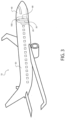
- Figure 3 is a diagram of an aircraft showing both internal components and external components in accordance with an aspect of the disclosure.
- a sensor system 100 may be mounted in an aircraft 10 within the cockpit 40 to monitor the pressure within the cockpit 40. Additionally, the pressure within an adjacent compartment, such as passenger compartment 50, a cargo compartment, or the like may also be monitored by the sensor system 100. If a large enough pressure drop, or change in pressure ⁇ P, is detected in the cockpit 40 (or, in some aspects, passenger compartment 50), the sensor system 100 sends a notification signal to another device, system, actuator, etc.
- a typical response to the notification signal provided by sensor system 100 may be, for example, activating a door latch 60 to open a cockpit door 30 to allow pressure equalization between the cockpit 40 and the passenger compartment 50.
- the sensor system 100 may be further configured to distinguish between percussive events such as a gunshot, small explosion, and the like and actual decompression events.
- Figure 4 is a diagram of an expanded section of the airplane of Figure 3 .
- Figure 4 is a diagram of the sensor system 100 that may include a system controller 103, that may be installed within the cockpit 40 or otherwise located within the aircraft 10.
- the system controller 103 may be coupled or responsive to a pressure sensor 110.
- the pressure sensor 110 may be an electronic absolute pressure sensitive device.
- the pressure sensor 110 senses the pressure within either the cockpit 40 or the passenger compartment 50.
- the pressure sensor 110 may be installed within cockpit 40, and a pressure sensor 112 may be remotely installed within the passenger compartment 50. If the pressure drop sensed by the pressure sensor 110 or the pressure sensor 112 is large enough, i.e., meets a predetermined pressure drop target, the system controller 103 may provide a notification signal to another device, system, apparatus, etc. The notification may include informing the pilot of a decompression event via a visual or an auditory indication. Additionally, the system controller 103 may activate the door latch 60 to open the cockpit door 30 to allow pressure equalization between the cockpit 40 and the passenger compartment 50.
- the pressure sensor 110 may be installed generally within the cockpit 40, such as, for example, on the partition 20, etc.; alternatively the pressure sensor 110 may be located within the system controller 103 and ported to the cockpit 40. Additionally, the various aspects the system controller 103, the pressure sensors 110 and 112, and the attendant cables, connectors, etc., may be shielded from tampering.
- the cockpit door 30 may be attached to the partition 20 by at least one hinge 42.
- the at least one hinge 42 being configured to hold the cockpit door 30 as well as to easily allow the cockpit door 30 to rotate between a closed position and an open position as indicated by arrow 44.
- the at least one hinge 42 may be mechanically fastened to the cockpit door 30 as well as mechanically fastened directly or indirectly to the partition 20, an intermediate structure such as a doorjamb to the partition 20, or the like.
- the at least one hinge 42 may be implemented utilizing any known hinge technology including spring hinge, barrel hinge, pivot hinges, butt/mortise hinges, case hinges, continuous hinges, or piano hinges, concealed hinges, butterfly hinges orInstitut hinges, flag hinges, strap hinges, H hinges, HL hinges, or the like.
- the cockpit door 30 further includes the shock absorber 200.
- the shock absorber 200 may be attached to the cockpit door 30 at one end; and the shock absorber 200 may be attached to an adjacent structure at another end.
- the adjacent structure may be a wall, a divider, a bulkhead, the partition 20, or the like.
- the shock absorber 200 may be configured to have at least two operational modes.
- the first operational mode being defined as a normal operational mode; and the second operational mode being defined as a decompression event mode.
- the first operational mode including scenarios where the pilot opens the cockpit door 30 to gain entry to the cockpit.
- the first operational mode being such that the cockpit door 30 is rotationally opened at a rate of door tip speed less than 10 ft./s.
- the first operational mode being such that the cockpit door 30 is rotationally opened at a rate of door tip speed less than 40 ft./s.
- the first operational mode being such that the cockpit door 30 is rotationally opened at a rate of door tip speed less than 67 ft./s
- the second operational mode being such that the cockpit door 30 is rotationally opened at a rate of door tip speed greater than the first operational mode.
- the second operational mode being a mode of operation during a decompression event.
- the cockpit door 30 may be formed of a synthetic material, a metallic material, or a combination thereof.
- the cockpit door 30 may include a substantially rectangular panel structure.
- the cockpit door 30 may include a lightweight armored panel.
- the cockpit door 30 and/or the associated panel may be adapted for ballistic resistance and structural integrity.
- the cockpit door 30 and/or associated panel may be configured to meet the FAA mandated requirements applied to aircraft interior doors and bulkheads for resistance to forcible intrusion by unauthorized persons and resistance to penetration by small arms fire and fragmentation devices.
- Various aspects of the cockpit door 30 and associated panel are described by Applicant's United States patent number 9,279,641 issued March 8, 2016 .
- Figure 5 is a diagram of an aircraft cockpit door and a cockpit door shock absorber in accordance with an aspect of the disclosure.
- Figure 5 illustrates a more detailed illustration of an exemplary installation of the shock absorber 200 with the cockpit door 30.
- the shock absorber 200 may be located vertically along any position of the cockpit door 30. In one aspect, the shock absorber 200 may be located close to a top of the cockpit door 30. Other locations are contemplated as well. Additionally, the shock absorber 200 is shown located on the cockpit door 30 inside the cockpit 40. Alternatively, the shock absorber 200 may be located on the cockpit door 30 inside the passenger compartment 50. In a further aspect, a first one of the shock absorber 200 may be located on the cockpit door 30 inside the cockpit 40 and a second one of the shock absorber 200 may be located on the cockpit door 30 inside the passenger compartment 50.
- the shock absorber 200 may be mechanically fastened to a first attachment 202.
- the first attachment 202 may be mechanically fastened to the cockpit door 30.
- the shock absorber 200 may be directly connected to the cockpit door 30.
- the shock absorber 200 may be connected to the cockpit door 30 through other intervening structures.
- the shock absorber 200 may be mechanically fastened to a second attachment 204.
- the second attachment 204 may be mechanically fastened to a wall, a divider, a bulkhead, the partition 20, or the like (hereinafter the partition 20).
- the shock absorber 200 may be directly connected to the partition 20.
- the shock absorber 200 may be connected to the partition 20 through other intervening structures.
- mechanically fastened as described herein is meant to include utilization of one or more of bolts, nuts, screws, rivets, adhesive, welding, crimping, pins, anchors, and the like.
- FIG. 5 further illustrates the door latch 60 that in some aspects may be implemented as a deadbolt.
- the door latch 60 may include a latch housing that is attached to a cockpit door 30 or is structured and arranged inside the cockpit door 30.
- the latch housing may include one or more mechanical fasteners to secure the latch housing to the cockpit door 30.
- the latch housing may include a latch bolt as well as supporting structure to allow the latch bolt to extend into a strike plate that is attached to a doorjamb.
- the door latch 60 may further include an actuator 306.
- the actuator 306 may be an electromechanical actuator, a pyrotechnic actuator, a mechanical actuator, or the like.
- the actuator 306 may be directly connected to the latch bolt and movement of the actuator 306 will likewise move the latch bolt to place the door latch 60 in a locked configuration such that the cockpit door 30 may remain closed.
- reverse movement of the actuator 306 will likewise move the latch bolt in a reverse direction to place the door latch 60 in an unlocked configuration such that the cockpit door 30 may open.
- the actuator 306 may include intervening mechanical components such that the movement noted above is mechanically applied to the latch bolt in a similar manner.
- the actuator 306 is responsive to a signal from the sensor system 100.
- the signal from the sensor system 100 being generated in response to a decompression event as described herein.
- the actuator 306 may be actuated such that it moves the latch bolt to place the cockpit door 30 in the unlocked and opened configuration. In this unlocked and opened configuration, air is able to travel between the passenger compartment 50 and the cockpit 40 and there is no or little pressure differential between the passenger compartment 50 in the cockpit 40 thus preventing or reducing any possible damage.
- Figure 6 is a block diagram of a system for monitoring pressure in at least one compartment of an aircraft in accordance with an aspect of the disclosure.
- the sensor system 100 generally includes at least one pressure sensor 110 coupled to the system controller 103.
- the system controller 103 may include at least a primary monitoring channel 105 and an output driver 150.
- the output driver 150 provides a driver signal associated with the decompression event to the door latch 60 to initiate the actuator 306 and open the cockpit door 30.
- the output driver 150 provides a driver signal associated with the decompression event to the at least one wire 356 and/or at least one wire 364 to initiate the actuator 306 and open the cockpit door 30.
- the system controller 103 may be implemented a number of different ways. In one aspect, the system controller 103 may be implemented by a dedicated analog circuit. In one aspect, the system controller 103 may be implemented by a dedicated computer processor. In one aspect, the system controller 103 may be implemented by an application specific integrated circuit (ASIC). In one aspect, the system controller 103 may be implemented by a field programmable gate array (FPGA). In one aspect, the system controller 103 may be implemented by the flight warning system. In one aspect, the system controller 103 may be implemented by an avionics system. In one aspect, the system controller 103 may be implemented by the central maintenance system.
- ASIC application specific integrated circuit
- FPGA field programmable gate array
- the system controller 103 may be implemented by any of the above noted systems and may be configured to provide one or more of the following described processes and/or functions.
- the system controller 103 may be configured such that the primary monitoring channel 105 may include a band pass filtering functionality, a pressure change determination functionality, and a pressure threshold determination functionality.
- the system controller 103 may implement digital signal processing capability and/or software for band pass filtering functionality, pressure change determination functionality, and pressure threshold determination functionality.
- the system controller 103 may be configured such that the primary monitoring channel 105 may include a band pass filter 120, a pressure change signal circuit 130, and a threshold logic circuit 140.
- the system controller 103 may include multiple monitoring channels 105 to 105-N, each of the N channels coupled to a respective pressure sensor 110-N.
- the pressure sensor 110 may provide a pressure signal corresponding to a pressure P 1 within the compartment of the aircraft 10, and the band pass filter 120 may receive and filter the pressure sensor signals.
- the band pass filter 120 may advantageously reduce the operational noise floor and provide sensitivity only to regions of interest.
- the pressure change signal circuit 130 receives the filtered pressure signal, determines a change in pressure ⁇ P 1 , and provides a pressure change output signal corresponding to the change in pressure ⁇ P 1 . This value may then be provided to the threshold logic circuit 140.
- the threshold logic circuit 140 determines whether the pressure change output signal meets a predetermined threshold and provides a threshold output signal, indicating that a decompression event has occurred, to the output driver 150 if the pressure change output meets the predetermined threshold.
- the output driver 150 provides a notification signal associated with the decompression event to the door latch 60 to initiate the actuator 306 and open the cockpit door 30.
- the output driver 150 provides a notification signal associated with the decompression event to another device, system, actuator, etc.
- the system controller 103 includes N monitoring channels 105 to 105-N, each of which is coupled to a respective pressure sensor 110-N.
- Each of the N monitoring channels is coupled to the output driver 150, which provides the notification signal if any N monitoring channel's threshold logic indicates a decompression event has occurred.
- the output driver 150 may operate based on a more advanced paradigm, such as a voting system in response to one or more N monitoring channel's threshold logic indicating a decompression event has occurred.
- the multiple monitoring channels may be used in a compartment to provide redundancy.
- Figure 7 is a flow chart of an exemplary method of the system controller monitoring pressure in a compartment of an aircraft system as described herein according .
- Figure 7 illustrates a process 900 for monitoring a primary monitoring channel 105.
- the process 900 may be implemented in hardware or software by the system controller 103 and/or the sensor system 100.
- the process 900 for the primary monitoring channel 105 may include receiving a pressure signal 902 corresponding to a pressure P 1 within a compartment of an aircraft 10 (such as, for example, cockpit 40).
- signals are filtered that are outside of a predetermined frequency band.
- the signals may be filtered by a filter or filter software implemented by the system controller 103 and/or the sensor system 100.
- a change in pressure ⁇ P 1 is determined 906 by the system controller 103 and/or the sensor system 100.
- the output driver 150 may transmit a signal over at least one wire 356 and/or at least one wire 364 to the door latch 60 to initiate the actuator 306.
- the output driver 150 provides a notification signal associated with the decompression event to the door latch 60 to initiate the actuator 306 and open the cockpit door 30.
- aspects of the disclosure may additionally include means for performing any of the above-described actions and/or steps.
- the disclosure has disclosed a mechanism that limits movement of the cockpit door 30 during episodes of decompression to limit damage and injury.
- the methods described herein are intended for operation with dedicated hardware implementations including, but not limited to, PCs, semiconductors, application specific integrated circuits (ASIC), programmable logic arrays, cloud computing devices, field programmable gate array (FPGA), and other hardware devices constructed to implement the methods described herein.
- dedicated hardware implementations including, but not limited to, PCs, semiconductors, application specific integrated circuits (ASIC), programmable logic arrays, cloud computing devices, field programmable gate array (FPGA), and other hardware devices constructed to implement the methods described herein.
- any software implementations of the disclosure as described herein are optionally stored on a tangible storage medium, such as: a magnetic medium such as a disk or tape; a magneto-optical or optical medium such as a disk; or a solid state medium such as a memory card or other package that houses one or more read-only (non-volatile) memories, random access memories, or other re-writable (volatile) memories.
- a digital file attachment to email or other self-contained information archive or set of archives is considered a distribution medium equivalent to a tangible storage medium. Accordingly, the disclosure is considered to include a tangible storage medium or distribution medium, as listed herein and including art-recognized equivalents and successor media, in which the software implementations herein are stored.
- the various aspects of the disclosure may be implemented in a non-generic computer implementation.
- the system controller 103 may be implemented as a decompression and door actuation controller; the sensor system 100 may be implemented as a decompression and door actuation system.
- the various aspects of the disclosure set forth herein improve the functioning of the system as is apparent from the disclosure hereof.
- the various aspects of the disclosure involve computer hardware that it specifically programmed to solve the complex problem addressed by the disclosure. Accordingly, the various aspects of the disclosure improve the functioning of the system overall in its specific implementation to perform the process set forth by the disclosure and as defined by the claims.
Landscapes
- Engineering & Computer Science (AREA)
- General Engineering & Computer Science (AREA)
- Mechanical Engineering (AREA)
- Aviation & Aerospace Engineering (AREA)
- Fluid-Damping Devices (AREA)
- Vibration Dampers (AREA)
Description
- This application claims the benefit of
U.S. Provisional Patent Application No. 62/618,546 filed January 17, 2018 - One aspect the disclosure relates to a cockpit door shock absorber configured with a deformable energy absorbing member. More specifically, one aspect of the disclosure relates to a cockpit door shock absorber configured for operation during decompression events.
- A shock absorber is typically a mechanical or hydraulic device designed to absorb and damp shock impulses. The shock absorber does this by converting the kinetic energy of the shock into another form of energy. This energy may typically be in the form of heat. Subsequently, the energy is then dissipated. Most shock absorbers are a form of dashpot (a damper which resists motion via viscous friction).
- However, a typical shock absorber has a limited operational envelope and cannot shock impulses or forces at extreme ends of an operational envelope needed in some specific applications. Failure to provide shock absorption in the specific applications that may be subject to an extreme range of forces may result in damage to the application to which the shock absorber is implemented or injury to individuals proximate to the application.
- Accordingly, what is needed is a shock absorber that provides an extreme range of shock absorption to an application to limit damage and injury.
- One such application is in aircraft. Aircraft are generally equipped with at least one cockpit door. The aircraft often has a separating partition that includes the at least one cockpit door that is located between a pilot, copilot, and/or flight crew (hereinafter referred to as "pilot") and passengers. The cockpit door provides security and privacy to the cockpit for the pilot. In this regard, the term "cockpit" refers to a location of the aircraft where the pilot is located during operation of the aircraft. The cockpit may also be known as the "flight deck." This is distinguished from the cabin, which refers to a portion of the aircraft where passengers are typically located.
- In many aircraft, it is required that the ambient air pressure in the cockpit be generally the same as the ambient air pressure in the passenger cabin of the aircraft. A dangerous situation may arise if there is a sufficiently great pressure difference between opposite sides of the cockpit door or any compartments separated by the partition within the aircraft. One cause of a pressure difference may be a loss of cockpit pressurization. Loss of cockpit pressurization is a potentially serious emergency in an aircraft flying at normal cruising altitude. Loss of cockpit pressure, or depressurization, is typically classified as explosive, rapid, or gradual, based on the time interval over which cockpit pressure is lost. A pressure difference caused by a loss of pressurization, depressurization, or decompression (hereinafter generally referred to as decompression) can cause structural deformation, structural damage, and possibly lead to the loss of the aircraft.
- Typically, the cockpit door may be locked or unlocked by operation of a door latch. The door latch may be a fully mechanical component, an electromechanical component, or the like. There exists some systems where the cockpit door may be opened by automatic operation of the door latch in response to a decompression event to limit damage. However, during such decompression, especially during explosive or rapid decompression, the cockpit door once automatically unlocked can be subjected to a great deal of force due to the pressure differential. This pressure differential and/or force results in the door opening at a very high rotational velocity about the associated hinges that results in possible structural deformation and/or structural damage to the door as well as the cockpit and other portions of the aircraft. Moreover, this scenario could also result in possible debris and flying parts within the cockpit that may damage critical aircraft controls and/or injure the pilot that could possibly lead to the loss of the aircraft.
-
DE202012100619U discloses a hydro-pneumatic adjustment element, which has a fluid-filled cylinder with an extendable piston rod and a piston, characterized in that the adjustment element has a crash element which in the event of an overload absorbs external forces and protects the other components of the adjusting element, in particular the piston rod. -
DE3836724 presents a deflection-type absorber for the fastening, in a yielding fashion, of a bumper to the frame side member of a vehicle body has a regenerating hydraulic, gas or solid shock absorber and a non-regenerating deformation element, which is arranged downstream of the latter, to take up energy. The deformation element and the operating cylinder of the shock absorber are arranged in a casing which is fastened to the frame side member. In order to allow the deflection-type absorber to be of simple design and be easy to disassemble, the casing takes the form of a guiding container which tightly encloses the operating cylinder and the deformation element takes the form of an energy absorber which fills the guiding container, while resting against the container floor, in the container section situated immediately in front of the container floor. To enable to deflection-type absorber to be fastened, there is fixedly connected to the guiding container a coaxially fastening plate in the vicinity of the edge of the container, the dimensions of the said fastening plate being such that it is supported by the end face of the hollow frame side member. - Accordingly, what is further needed is a mechanism that limits movement of the cockpit door during episodes of decompression to limit damage and injury.
- In accordance with the present invention there is provided an aircraft system comprising a combination of an aircraft cockpit door pivotally mounted within a partition for separating an aircraft cockpit from an aircraft passenger cabin and a shock absorber fastened thereto as defined in the appended
independent claim 1, and a process of implementing an aircraft system comprising an aircraft cockpit door pivotally mounted within a partition for separating an aircraft cockpit from an aircraft passenger cabin and a shock absorber, as defined in the appendedindependent claim 10. Preferred embodiments are defined in the dependent claims. -
-
Figure 1 is a diagram of a shock absorber in accordance with an aspect of the disclosure. -
Figure 2 is a diagram of a shock absorber in accordance with another aspect of the disclosure. -
Figure 3 is a diagram of an aircraft showing both internal components and external components in accordance with an aspect of the disclosure. -
Figure 4 is a diagram of an expanded section of the airplane ofFigure 3 . -
Figure 5 is a diagram of an aircraft cockpit door and a cockpit door shock absorber in accordance with an aspect of the disclosure. -
Figure 6 is a block diagram of a system for monitoring pressure in an aircraft in accordance with an aspect of the disclosure. -
Figure 7 is a flow chart of a method of monitoring pressure in an aircraft according to an aspect of the disclosure. - Aspects of the disclosure are directed to an aircraft system comprising an aircraft cockpit door pivotally mounted within a partition for separating an aircraft cockpit from an aircraft passenger cabin and a shock absorber with a crushable or deformable energy absorber or dissipater member. In particular, the disclosure discloses a shock absorber with two added members (secondary piston and crushable foam/honeycomb) that is designed to crush if the force or energy applied to the shock absorber exceeds a set limit. In this regard, if the primary piston is moved very fast and a fluid cannot exit an orifice fast enough, the fluid is compressed and its pressure is increased, which causes the secondary piston to move and start crushing the crushable member. This functionality thus dissipating or absorbing the energy by deforming the crushable member permanently or temporarily. In various aspects, the shock absorber is designed to transmit the energy in a direct or indirect manner to the crushable member. The disclosure sets forth at least two different aspects, but other geometries are possible to direct the energy that needs to be dissipated to the deformable member.
- Further aspects of the disclosure advantageously provide a cockpit door shock absorber configured for operation during decompression events to limit damage and/or injuries.
- One general aspect of the system as claimed includes a shock absorber, including: a first end configured to be mechanically fastened to a first component. The shock absorber also includes a second end configured to be mechanically fastened to a second component. The shock absorber also includes a main body that is attached to the first end. The shock absorber also includes a main shaft that is attached to the second end. The shock absorber also includes a primary piston configured to be received in the main body. The shock absorber also includes the primary piston being attached to the main shaft and the primary piston being further configured to be movable with the main shaft. The shock absorber also includes the primary piston configured to move within the main body and further configured to provide a first damping force by movement of a fluid through the primary piston while the main shaft moves a first distance. The shock absorber also includes a deformable solid material arranged in the main body. The shock absorber also includes the primary piston configured to further move within the main body and further configured to provide a second damping force by deforming the deformable solid material after the main shaft moves the first distance. The shock absorber also includes where one of the first component and the second component includes a fixed structure. The shock absorber also includes where another one of the first component and the second component includes a movable structure.
- One aspect includes a process of implementing an aircraft system comprising an aircraft cockpit door pivotally mounted within a partition for separating an aircraft cockpit from an aircraft passenger cabin and a shock absorber, including: configuring a first end to be mechanically fastened to a first component. The process of implementing also includes configuring a second end to be mechanically fastened to a second component. The process of implementing also includes configuring a main body to be attached to the first end. The process of implementing also includes configuring a main shaft to be attached to the second end. The process of implementing also includes configuring a primary piston to be received in the main body. The process of implementing also includes configuring the primary piston to be attached to the main shaft and the primary piston being further configured to be movable with the main shaft. The process of implementing also includes configuring the primary piston to move within the main body to provide a first damping force by movement of a fluid through the primary piston while the main shaft moves a first distance. The process of implementing also includes configuring a deformable solid material in the main body. The process of implementing also includes configuring the primary piston to further move within the main body to provide a second damping force by deforming the deformable solid material after the main shaft moves the first distance. The process of implementing also includes where one of the first component and the second component includes a fixed structure. The process of implementing also includes where another one of the first component and the second component includes a movable structure.
- There has thus been outlined, rather broadly, certain aspects of the disclosure in order that the detailed description thereof herein may be better understood, and in order that the present contribution to the art may be better appreciated. There are, of course, additional aspects of the disclosure that will be described below and which will form the subject matter of the claims appended hereto.
- In this respect, before explaining at least one aspect of the disclosure in detail, it is to be understood that the disclosure is not limited in its application to the details of construction and to the arrangements of the components set forth in the following description or illustrated in the drawings. The disclosure is capable of aspects in addition to those described and of being practiced and carried out in various ways. Also, it is to be understood that the phraseology and terminology employed herein, as well as the abstract, are for the purpose of description and should not be regarded as limiting.
- As such, those skilled in the art will appreciate that the conception upon which this disclosure is based may readily be utilized as a basis for the designing of other structures, methods and systems for carrying out the several purposes of the disclosure. The full scope of protection is therefore only defined by the wording of the appended claims.
- The disclosure will now be described with reference to the drawing figures, in which like reference numerals refer to like parts throughout.
-
Figure 1 is a diagram of a shock absorber belonging to an aircraft system in accordance with an aspect of the disclosure; andFigure 2 is a diagram of a shock absorber belonging to an aircraft system in accordance with another aspect of the disclosure. - In particular,
Figures 1 and2 illustrate a cross-sectional view of ashock absorber 200. Theshock absorber 200 may include afirst end 220 and asecond end 222. In one aspect, thefirst end 220 may be configured as a clevis having afastener reception portion 224 that may be configured to be mechanically fastened to another structure. In one aspect, thesecond end 222 may be configured as a clevis having afastener reception portion 226 that may be configured to may be mechanically fastened to another structure. As illustrated inFigure 5 , thefirst end 220 is mechanically fastened to afirst attachment 202 that is mechanically fastened to acockpit door 30. Thefirst end 220 is be mechanically fastened to thecockpit door 30. In one aspect, thefirst end 220 may be mechanically fastened to thecockpit door 30 through other intervening structures. In one aspect, thefirst end 220 may be mechanically fastened to thesecond attachment 204, which is mechanically fastened to the door post, the door frame, a wall, a divider, a bulkhead, thepartition 20, or the like (hereinafter the partition 20). In one aspect, thefirst end 220 may be mechanically fastened directly to apartition 20. In one aspect, thefirst end 220 may be mechanically fastened to thepartition 20 through other intervening structures. In one aspect, thesecond end 222 is mechanically fastened directly and/or indirectly to a fixed or movable structure. - In one aspect relating to the aircraft implementation described herein and illustrated in
Figure 5 , thesecond end 222 may be mechanically fastened to thefirst attachment 202 that may be mechanically fastened to thecockpit door 30. In one aspect, thesecond end 222 may be mechanically fastened to thecockpit door 30. In one aspect, thesecond end 222 may be mechanically fastened to thecockpit door 30 through other intervening structures. In one aspect, thesecond end 222 may be mechanically fastened to thesecond attachment 204, which be mechanically fastened to a door post, a door frame, a wall, a divider, a bulkhead, thepartition 20, or the like (hereinafter the partition 20). In one aspect, thesecond end 222 may be mechanically fastened directly to thepartition 20. In one aspect, thesecond end 222 may be mechanically fastened to thepartition 20 through other intervening structures. - The
shock absorber 200 includes amain body 214 that is directly or indirectly connected to thefirst end 220. Themain body 214 may have a cylindrical, square, polygonal or other shape cross section. Themain body 214 may be made from a metallic material, a synthetic material, or the like. In one aspect, themain body 214 may be integral with thefirst end 220. In one aspect, themain body 214 may be mechanically fastened to thefirst end 220 through anattachment portion 232. - The
shock absorber 200 includes amain shaft 206. Themain shaft 206 may have a cylindrical, square, polygonal or other shape cross section. Themain shaft 206 may be made from a metallic material, a synthetic material, or the like. In one aspect, themain shaft 206 may be integral with thesecond end 222. In one aspect, themain shaft 206 may be mechanically fastened to thesecond end 222. - The
main shaft 206 may be partially located in themain body 214 and may be partially located extending from themain body 214. In one aspect, themain shaft 206 may extend through anend cap 230 that is mechanically fastened or integral with themain body 214. - The
shock absorber 200 includes aprimary piston 208. Theprimary piston 208 may have a cylindrical, square, polygonal or other shape cross section. Theprimary piston 208 may be made from a metallic material, a synthetic material, or the like. In one aspect, theprimary piston 208 may be integral with themain shaft 206. In one aspect, theprimary piston 208 may be mechanically fastened to themain shaft 206. Theprimary piston 208 is located within themain body 214. - The
main body 214 may further be configured to include a partially closed portion defining afirst fluid volume 216 and may be further configured to include a partially closed portion defining asecond fluid volume 228. Thefirst fluid volume 216 and thesecond fluid volume 228 may be configured to contain a fluid. The fluid may be a liquid such as an oil, hydraulic oil, a gas such as nitrogen, or the like. - The
primary piston 208 may be configured with anorifice 218 extending along a longitudinal length of theprimary piston 208. Theprimary piston 208 may be positioned in themain body 214 between thefirst fluid volume 216 and thesecond fluid volume 228. Theorifice 218 may fluidly connect thefirst fluid volume 216 and thesecond fluid volume 228. - During the first operational mode as defined herein, the distance between the
first end 220 and thesecond end 222 may vary by movement of themain shaft 206 and theprimary piston 208 into themain body 214. In particular, during movement of the movable structure, themain shaft 206 may be forced into themain body 214 and move theprimary piston 208 toward thefirst end 220. For example, during opening of thecockpit door 30, themain shaft 206 will be forced into themain body 214 and move theprimary piston 208 toward thefirst end 220. During this movement, theprimary piston 208 will reduce the volume of thefirst fluid volume 216 and the fluid in thefirst fluid volume 216 may travel through theorifice 218 into thesecond fluid volume 228. Accordingly, the volume of thesecond fluid volume 228 will increase. - Further during the first operational mode as defined herein, during reverse movement of the movable structure, the
main shaft 206 will be retracted from themain body 214 and move theprimary piston 208 away from thefirst end 220. For example, during closing of thecockpit door 30, themain shaft 206 will be retracted from themain body 214 and move theprimary piston 208 away from thefirst end 220. During this movement, theprimary piston 208 will decrease the volume of thesecond fluid volume 228 and the fluid in thesecond fluid volume 228 may travel through theorifice 218 into thefirst fluid volume 216. Accordingly, the volume of thefirst fluid volume 216 will increase. - The above-noted operation during the first operational mode provides a damped movement of the movable structure or the
cockpit door 30 by operation of the movement of the fluid between thefirst fluid volume 216 and thesecond fluid volume 228 through theorifice 218. Accordingly, movement of the movable structure or thecockpit door 30 may be slowed during the first operational mode. Moreover, the movement of the movable structure or thecockpit door 30 may be limited by the size of thefirst fluid volume 216 and thesecond fluid volume 228. Once movement of theprimary piston 208 decreases a volume of thefirst fluid volume 216 or thesecond fluid volume 228 to zero, near zero, or the pressure of the fluid exceeds a set value, movement of the movable structure or thecockpit door 30 may be impeded with the exception of the second operational mode described in further detail below. - The
main body 214 further includes adeformable material 212. Thedeformable material 212 is arranged within themain body 214 between thefirst end 220 and thefirst fluid volume 216. Thedeformable material 212 is a solid material. In one aspect, thedeformable material 212 may include a honeycomb shaped structure. In other aspects, thedeformable material 212 may be implemented using other materials that may provide a resilience or crushing for damping movement of theprimary piston 208 or absorbing energy of the movement of theprimary piston 208 consistent with the disclosure. - In one aspect, the honeycomb shaped structure may have an array of hollow cells formed between thin vertical walls. The hollow cells may have a columnar and hexagonal shape. The honeycomb shaped structure may implement the
deformable material 212 with minimal density and relative high out-of-plane compression properties and out-of-plane shear properties. The honeycomb shaped structure may be constructed of a synthetic material, composite material, metallic material, a natural material, or the like. In one aspect, the honeycomb shaped material may be a PLASCORE™ crushable material (available from PLASCORE™, Zeeland, Michigan, U.S.A.) such as AltuCore. In one aspect, a longitudinal length of the columns of the honeycomb structure may be arranged perpendicular to the longitudinal axis that extends between thefirst end 220 and thesecond end 222. In another aspect, a longitudinal length of the columns of the honeycomb structure may be arranged parallel to the longitudinal axis that extends between thefirst end 220 and thesecond end 222. - As described in further detail below, during a decompression event, a
sensor system 100 may actuate anactuator 306 associated with adoor latch 60 and open thecockpit door 30. In certain scenarios, the pressure differential between thecockpit 40 and thepassenger compartment 50 may be large enough such that a force is realized on thecockpit door 30 causing thecockpit door 30 to swing violently open at a high velocity. A velocity that is greater than the first operational mode velocity as defined herein. Theshock absorber 200 may be arranged as described herein with thecockpit door 30 to reduce the velocity of the movement of thecockpit door 30. - Initially, the
shock absorber 200 may operate in the first operational mode to provide a damped movement of the movable structure or thecockpit door 30 by operation of the movement of the fluid between thefirst fluid volume 216 and thesecond fluid volume 228 through theorifice 218. Thereafter, if the pressure realized on the movable structure or thecockpit door 30 results in continued movement of the movable structure or thecockpit door 30, theshock absorber 200 may operate in the second operational mode. - In the second operational mode, the
main shaft 206 as well as theprimary piston 208 continue move toward thefirst end 220. In this regard, the continued movement of themain shaft 206 as well as theprimary piston 208 may start to crush thedeformable material 212. Thedeformable material 212 will absorb the energy of the continued movement of themain shaft 206 as well as theprimary piston 208 and reduce the rotational velocity of thecockpit door 30. This reduces the possibility of damage, injury, and the like from the movement of thecockpit door 30 during a decompression event. In one aspect, if theprimary piston 208 is moved very fast and the fluid cannot exit theorifice 218 fast enough, the fluid is compressed and its pressure is increased, which causes crushing of thedeformable material 212. This functionality thus dissipating or absorbing the energy by deforming thedeformable material 212 permanently or temporarily. In various aspects, theshock absorber 200 is designed to transmit the energy in a direct or indirect manner to thedeformable material 212. - In a particular aspect of
Figure 1 , thefirst fluid volume 216, theprimary piston 208, and thesecond fluid volume 228 may all be further housed within acylinder body 210. Thecylinder body 210 may have a cylindrical, square, polygonal or other shape cross section. Thecylinder body 210 may be made from a metallic material, a synthetic material, or the like. In this aspect, during the second operational mode, themain shaft 206 as well as theprimary piston 208 continue move toward thefirst end 220. In this regard, the continued movement of themain shaft 206 as well as theprimary piston 208 along with thecylinder body 210 may start to crush thedeformable material 212. Thedeformable material 212 will absorb the energy of the continued movement of themain shaft 206, theprimary piston 208, and thecylinder body 210 and reduce the rotational velocity of thecockpit door 30. - In some aspects, the
first fluid volume 216, theprimary piston 208, thesecond fluid volume 228, and thecylinder body 210 may be further housed in ahousing 234 which may surround each of these components. In other aspects, thehousing 234 may simply be a wall between thefirst fluid volume 216 and thedeformable material 212. - In a particular aspect of
Figure 2 , thefirst fluid volume 216, theprimary piston 208, and thesecond fluid volume 228 may all be arranged adjacent asecondary piston 302. Thesecondary piston 302 may have a cylindrical, square, polygonal or other shape cross section. Thesecondary piston 302 may be made from a metallic material, a synthetic material, or the like. In this aspect, during the second operational mode, themain shaft 206 as well as theprimary piston 208 may continue to move toward thefirst end 220. In this regard, the continued movement of themain shaft 206 as well as theprimary piston 208 may force thesecondary piston 302 to move, which may start to crush thedeformable material 212. Thedeformable material 212 will absorb the energy of the continued movement of themain shaft 206, theprimary piston 208, and thesecondary piston 302 and reduce the rotational velocity of thecockpit door 30. - Accordingly, the
shock absorber 200 may be configured for operation in the first operational mode and the second operational mode as defined herein. Theshock absorber 200 may operate in the first operational mode by operating theshock absorber 200 based on a fluid damping structure that is implemented at least by theprimary piston 208, thefirst fluid volume 216, thesecond fluid volume 228, theorifice 218 and the fluid associated therewith. Theshock absorber 200 may operate in the second operational mode by operating theshock absorber 200 based on a solid deformable energy absorbing material that is implemented at least by theprimary piston 208 and thedeformable material 212. - Accordingly, the disclosure has described a
shock absorber 200 that provides an extreme range of shock absorption to an application to limit damage and injury. -
Figure 3 is a diagram of an aircraft showing both internal components and external components in accordance with an aspect of the disclosure. - As depicted in
Figure 3 , asensor system 100 may be mounted in anaircraft 10 within thecockpit 40 to monitor the pressure within thecockpit 40. Additionally, the pressure within an adjacent compartment, such aspassenger compartment 50, a cargo compartment, or the like may also be monitored by thesensor system 100. If a large enough pressure drop, or change in pressure ΔP, is detected in the cockpit 40 (or, in some aspects, passenger compartment 50), thesensor system 100 sends a notification signal to another device, system, actuator, etc. - For those aspects in which both the
cockpit 40 and thepassenger compartment 50 are monitored, a typical response to the notification signal provided bysensor system 100 may be, for example, activating adoor latch 60 to open acockpit door 30 to allow pressure equalization between thecockpit 40 and thepassenger compartment 50. Thesensor system 100 may be further configured to distinguish between percussive events such as a gunshot, small explosion, and the like and actual decompression events. -
Figure 4 is a diagram of an expanded section of the airplane ofFigure 3 . - In particular,
Figure 4 is a diagram of thesensor system 100 that may include asystem controller 103, that may be installed within thecockpit 40 or otherwise located within theaircraft 10. Thesystem controller 103 may be coupled or responsive to apressure sensor 110. In one aspect, thepressure sensor 110 may be an electronic absolute pressure sensitive device. - In one aspect, the
pressure sensor 110 senses the pressure within either thecockpit 40 or thepassenger compartment 50. In one aspect, thepressure sensor 110 may be installed withincockpit 40, and a pressure sensor 112 may be remotely installed within thepassenger compartment 50. If the pressure drop sensed by thepressure sensor 110 or the pressure sensor 112 is large enough, i.e., meets a predetermined pressure drop target, thesystem controller 103 may provide a notification signal to another device, system, apparatus, etc. The notification may include informing the pilot of a decompression event via a visual or an auditory indication. Additionally, thesystem controller 103 may activate thedoor latch 60 to open thecockpit door 30 to allow pressure equalization between thecockpit 40 and thepassenger compartment 50. - The
pressure sensor 110 may be installed generally within thecockpit 40, such as, for example, on thepartition 20, etc.; alternatively thepressure sensor 110 may be located within thesystem controller 103 and ported to thecockpit 40. Additionally, the various aspects thesystem controller 103, thepressure sensors 110 and 112, and the attendant cables, connectors, etc., may be shielded from tampering. - The
cockpit door 30 may be attached to thepartition 20 by at least onehinge 42. The at least onehinge 42 being configured to hold thecockpit door 30 as well as to easily allow thecockpit door 30 to rotate between a closed position and an open position as indicated byarrow 44. In particular, the at least onehinge 42 may be mechanically fastened to thecockpit door 30 as well as mechanically fastened directly or indirectly to thepartition 20, an intermediate structure such as a doorjamb to thepartition 20, or the like. The at least onehinge 42 may be implemented utilizing any known hinge technology including spring hinge, barrel hinge, pivot hinges, butt/mortise hinges, case hinges, continuous hinges, or piano hinges, concealed hinges, butterfly hinges or parliament hinges, flag hinges, strap hinges, H hinges, HL hinges, or the like. - The
cockpit door 30 further includes theshock absorber 200. Theshock absorber 200 may be attached to thecockpit door 30 at one end; and theshock absorber 200 may be attached to an adjacent structure at another end. The adjacent structure may be a wall, a divider, a bulkhead, thepartition 20, or the like. - The
shock absorber 200 may be configured to have at least two operational modes. The first operational mode being defined as a normal operational mode; and the second operational mode being defined as a decompression event mode. The first operational mode including scenarios where the pilot opens thecockpit door 30 to gain entry to the cockpit. In one aspect, the first operational mode being such that thecockpit door 30 is rotationally opened at a rate of door tip speed less than 10 ft./s. In one aspect, the first operational mode being such that thecockpit door 30 is rotationally opened at a rate of door tip speed less than 40 ft./s. In one aspect, the first operational mode being such that thecockpit door 30 is rotationally opened at a rate of door tip speed less than 67 ft./s - The second operational mode being such that the
cockpit door 30 is rotationally opened at a rate of door tip speed greater than the first operational mode. The second operational mode being a mode of operation during a decompression event. - The
cockpit door 30 may be formed of a synthetic material, a metallic material, or a combination thereof. Thecockpit door 30 may include a substantially rectangular panel structure. In one aspect, thecockpit door 30 may include a lightweight armored panel. Thecockpit door 30 and/or the associated panel may be adapted for ballistic resistance and structural integrity. In one particular aspect, thecockpit door 30 and/or associated panel may be configured to meet the FAA mandated requirements applied to aircraft interior doors and bulkheads for resistance to forcible intrusion by unauthorized persons and resistance to penetration by small arms fire and fragmentation devices. Various aspects of thecockpit door 30 and associated panel are described by Applicant'sUnited States patent number 9,279,641 issued March 8, 2016 -
Figure 5 is a diagram of an aircraft cockpit door and a cockpit door shock absorber in accordance with an aspect of the disclosure. - In particular,
Figure 5 illustrates a more detailed illustration of an exemplary installation of theshock absorber 200 with thecockpit door 30. Theshock absorber 200 may be located vertically along any position of thecockpit door 30. In one aspect, theshock absorber 200 may be located close to a top of thecockpit door 30. Other locations are contemplated as well. Additionally, theshock absorber 200 is shown located on thecockpit door 30 inside thecockpit 40. Alternatively, theshock absorber 200 may be located on thecockpit door 30 inside thepassenger compartment 50. In a further aspect, a first one of theshock absorber 200 may be located on thecockpit door 30 inside thecockpit 40 and a second one of theshock absorber 200 may be located on thecockpit door 30 inside thepassenger compartment 50. - In one aspect, the
shock absorber 200 may be mechanically fastened to afirst attachment 202. Thefirst attachment 202 may be mechanically fastened to thecockpit door 30. In other aspects, theshock absorber 200 may be directly connected to thecockpit door 30. In other aspects, theshock absorber 200 may be connected to thecockpit door 30 through other intervening structures. - In one aspect, the
shock absorber 200 may be mechanically fastened to asecond attachment 204. Thesecond attachment 204 may be mechanically fastened to a wall, a divider, a bulkhead, thepartition 20, or the like (hereinafter the partition 20). In other aspects, theshock absorber 200 may be directly connected to thepartition 20. In other aspects, theshock absorber 200 may be connected to thepartition 20 through other intervening structures. - In various aspects, mechanically fastened as described herein is meant to include utilization of one or more of bolts, nuts, screws, rivets, adhesive, welding, crimping, pins, anchors, and the like.
-
Figure 5 further illustrates thedoor latch 60 that in some aspects may be implemented as a deadbolt. Thedoor latch 60 may include a latch housing that is attached to acockpit door 30 or is structured and arranged inside thecockpit door 30. The latch housing may include one or more mechanical fasteners to secure the latch housing to thecockpit door 30. The latch housing may include a latch bolt as well as supporting structure to allow the latch bolt to extend into a strike plate that is attached to a doorjamb. - The
door latch 60 may further include anactuator 306. Theactuator 306 may be an electromechanical actuator, a pyrotechnic actuator, a mechanical actuator, or the like. Theactuator 306 may be directly connected to the latch bolt and movement of theactuator 306 will likewise move the latch bolt to place thedoor latch 60 in a locked configuration such that thecockpit door 30 may remain closed. In a similar manner, reverse movement of theactuator 306 will likewise move the latch bolt in a reverse direction to place thedoor latch 60 in an unlocked configuration such that thecockpit door 30 may open. In other aspects, theactuator 306 may include intervening mechanical components such that the movement noted above is mechanically applied to the latch bolt in a similar manner. - The
actuator 306 is responsive to a signal from thesensor system 100. The signal from thesensor system 100 being generated in response to a decompression event as described herein. After receiving the signal from thesensor system 100, theactuator 306 may be actuated such that it moves the latch bolt to place thecockpit door 30 in the unlocked and opened configuration. In this unlocked and opened configuration, air is able to travel between thepassenger compartment 50 and thecockpit 40 and there is no or little pressure differential between thepassenger compartment 50 in thecockpit 40 thus preventing or reducing any possible damage. -
Figure 6 is a block diagram of a system for monitoring pressure in at least one compartment of an aircraft in accordance with an aspect of the disclosure. - The
sensor system 100 generally includes at least onepressure sensor 110 coupled to thesystem controller 103. Thesystem controller 103 may include at least aprimary monitoring channel 105 and anoutput driver 150. In one aspect, theoutput driver 150 provides a driver signal associated with the decompression event to thedoor latch 60 to initiate theactuator 306 and open thecockpit door 30. In particular, theoutput driver 150 provides a driver signal associated with the decompression event to the at least one wire 356 and/or at least one wire 364 to initiate theactuator 306 and open thecockpit door 30. - The
system controller 103 may be implemented a number of different ways. In one aspect, thesystem controller 103 may be implemented by a dedicated analog circuit. In one aspect, thesystem controller 103 may be implemented by a dedicated computer processor. In one aspect, thesystem controller 103 may be implemented by an application specific integrated circuit (ASIC). In one aspect, thesystem controller 103 may be implemented by a field programmable gate array (FPGA). In one aspect, thesystem controller 103 may be implemented by the flight warning system. In one aspect, thesystem controller 103 may be implemented by an avionics system. In one aspect, thesystem controller 103 may be implemented by the central maintenance system. - The
system controller 103 may be implemented by any of the above noted systems and may be configured to provide one or more of the following described processes and/or functions. In one aspect, thesystem controller 103 may be configured such that theprimary monitoring channel 105 may include a band pass filtering functionality, a pressure change determination functionality, and a pressure threshold determination functionality. In one aspect, thesystem controller 103 may implement digital signal processing capability and/or software for band pass filtering functionality, pressure change determination functionality, and pressure threshold determination functionality. In one aspect, thesystem controller 103 may be configured such that theprimary monitoring channel 105 may include aband pass filter 120, a pressurechange signal circuit 130, and athreshold logic circuit 140. In other aspects, thesystem controller 103 may includemultiple monitoring channels 105 to 105-N, each of the N channels coupled to a respective pressure sensor 110-N. - The
pressure sensor 110 may provide a pressure signal corresponding to a pressure P1 within the compartment of theaircraft 10, and theband pass filter 120 may receive and filter the pressure sensor signals. Theband pass filter 120 may advantageously reduce the operational noise floor and provide sensitivity only to regions of interest. - The pressure
change signal circuit 130 receives the filtered pressure signal, determines a change in pressure ΔP1, and provides a pressure change output signal corresponding to the change in pressure ΔP1. This value may then be provided to thethreshold logic circuit 140. Thethreshold logic circuit 140 determines whether the pressure change output signal meets a predetermined threshold and provides a threshold output signal, indicating that a decompression event has occurred, to theoutput driver 150 if the pressure change output meets the predetermined threshold. - In one aspect, the
output driver 150 provides a notification signal associated with the decompression event to thedoor latch 60 to initiate theactuator 306 and open thecockpit door 30. - In additional aspects, the
output driver 150 provides a notification signal associated with the decompression event to another device, system, actuator, etc. - In an aspect that include
N pressure sensors 110 to 110-N, thesystem controller 103 includesN monitoring channels 105 to 105-N, each of which is coupled to a respective pressure sensor 110-N. Each of the N monitoring channels is coupled to theoutput driver 150, which provides the notification signal if any N monitoring channel's threshold logic indicates a decompression event has occurred. Alternatively, theoutput driver 150 may operate based on a more advanced paradigm, such as a voting system in response to one or more N monitoring channel's threshold logic indicating a decompression event has occurred. In addition, the multiple monitoring channels may be used in a compartment to provide redundancy. -
Figure 7 is a flow chart of an exemplary method of the system controller monitoring pressure in a compartment of an aircraft system as described herein according . - In particular,
Figure 7 illustrates aprocess 900 for monitoring aprimary monitoring channel 105. It should be appreciated that, if additional monitoring channels are used, there would be a similar process associated with each monitoring channel. Theprocess 900 may be implemented in hardware or software by thesystem controller 103 and/or thesensor system 100. Theprocess 900 for theprimary monitoring channel 105 may include receiving apressure signal 902 corresponding to a pressure P1 within a compartment of an aircraft 10 (such as, for example, cockpit 40). - In one aspect, at
step 904, signals are filtered that are outside of a predetermined frequency band. In particular, the signals may be filtered by a filter or filter software implemented by thesystem controller 103 and/or thesensor system 100. - Next, a change in pressure ΔP1 is determined 906 by the
system controller 103 and/or thesensor system 100. - At
step 908, a determination is made as to whether the pressure change ΔP1 meets a predetermined threshold. In theillustrated step 908, a greater than or equal to comparison is made, although the disclosure is not intended to be so limited. If the determination is NO, then theprocess 900 returns to step 902. If the determination is YES, then a notification signal is provided indicating that a decompression event has occurred 910, which is generated by thesystem controller 103 and/or thesensor system 100. - At
step 912, theoutput driver 150 may transmit a signal over at least one wire 356 and/or at least one wire 364 to thedoor latch 60 to initiate theactuator 306. In one aspect, theoutput driver 150 provides a notification signal associated with the decompression event to thedoor latch 60 to initiate theactuator 306 and open thecockpit door 30. - Aspects of the disclosure may additionally include means for performing any of the above-described actions and/or steps.
- Accordingly, the disclosure has disclosed a mechanism that limits movement of the
cockpit door 30 during episodes of decompression to limit damage and injury. - Further in accordance with various aspects of the disclosure, the methods described herein are intended for operation with dedicated hardware implementations including, but not limited to, PCs, semiconductors, application specific integrated circuits (ASIC), programmable logic arrays, cloud computing devices, field programmable gate array (FPGA), and other hardware devices constructed to implement the methods described herein.
- It should also be noted that any software implementations of the disclosure as described herein are optionally stored on a tangible storage medium, such as: a magnetic medium such as a disk or tape; a magneto-optical or optical medium such as a disk; or a solid state medium such as a memory card or other package that houses one or more read-only (non-volatile) memories, random access memories, or other re-writable (volatile) memories. A digital file attachment to email or other self-contained information archive or set of archives is considered a distribution medium equivalent to a tangible storage medium. Accordingly, the disclosure is considered to include a tangible storage medium or distribution medium, as listed herein and including art-recognized equivalents and successor media, in which the software implementations herein are stored.
- Additionally, the various aspects of the disclosure may be implemented in a non-generic computer implementation. For example, the
system controller 103 may be implemented as a decompression and door actuation controller; thesensor system 100 may be implemented as a decompression and door actuation system. Moreover, the various aspects of the disclosure set forth herein improve the functioning of the system as is apparent from the disclosure hereof. Furthermore, the various aspects of the disclosure involve computer hardware that it specifically programmed to solve the complex problem addressed by the disclosure. Accordingly, the various aspects of the disclosure improve the functioning of the system overall in its specific implementation to perform the process set forth by the disclosure and as defined by the claims. - The many features and advantages of the disclosure are apparent from the detailed specification, and, thus, it is intended by the appended claims to cover all such features and advantages of the disclosure which fall within the true scope of the claims.
Claims (13)
- An aircraft system comprising a combination of an aircraft cockpit door (30) pivotally mounted within a partition (20) for separating an aircraft cockpit from an aircraft passenger cabin and a shock absorber (200) fastened thereto, the shock absorber (200), comprising:a first end (220) configured to be mechanically fastened to a first component;a second end (222) configured to be mechanically fastened to a second component;a main body (214) that is attached to the first end (220);a main shaft (206) that is attached to the second end (222);a primary piston (208) configured to be received in the main body (214);the primary piston (208) being attached to the main shaft (206) and the primary piston (208) being further configured to be movable with the main shaft (206);the primary piston (208) configured to move within the main body (214) and further configured to provide a first damping force by movement of a fluid through the primary piston (208) while the main shaft (206) moves a first distance;a deformable solid material (212) arranged in the main body (214); andthe primary piston (208) configured to further move within the main body (214) and further configured to provide a second damping force by deforming the deformable solid material (212) after the main shaft (206) moves the first distance,wherein one of the first component and the second component comprises a fixed structure;wherein the other one of the first component and the second component comprises a movable structure; andwherein the movable structure is the aircraft cockpit door (30), pivotally mounted within the partition (20) separating the aircraft cockpit from the aircraft passenger cabin.
- The aircraft system of claim 1, wherein the shock absorber (200) further comprises:a secondary cylinder body (210) configured to receive the primary piston (208); andthe secondary cylinder body (210) configured to be received in the main body (214),wherein the secondary cylinder body (210) is configured to further move within the main body (214) and further configured to provide the second damping force by deforming the deformable solid material (212) after the main shaft (206) moves the first distance.
- The aircraft system of claim 1, wherein the shock absorber (200) further comprises:a secondary piston body (302) configured to be received in the main body (214); andthe secondary piston body (302) configured to be moved in the main body (214) by movement of the primary piston (208),wherein the secondary piston body (302) is configured to further move within the main body (214) and further configured to provide the second damping force by deforming the deformable solid material (212) after the main shaft (206) moves the first distance.
- The aircraft system of claim 1, wherein the shock absorber (200) further comprises:
an orifice arranged in the primary piston (208) configured to transfer the fluid through the primary piston (208). - The aircraft system of claim 1, The shock absorber of claim 1,
wherein the deformable solid material (212) comprises a honeycomb structure. - The aircraft system of claim 1, wherein the shock absorber (200) further comprises:a first fluid volume arranged on one side of the primary piston (208) within the main body (214); anda second fluid volume arranged on another side of the primary piston (208) within the main body (214).
- The aircraft system of claim 1, wherein the shock absorber (200) further comprises:a first fluid volume arranged on one side of the primary piston (208) within the main body (214);a second fluid volume arranged on another side of the primary piston (208) within the main body (214); andan orifice arranged in the primary piston (208) configured to transfer the fluid through the primary piston (208) between the first fluid volume and the second fluid volume.
- The aircraft system of claim 1, wherein the shock absorber (200) further comprises:a first fluid volume arranged on one side of the primary piston (208) within the main body (214);a second fluid volume arranged on another side of the primary piston (208) within the main body (214); andan orifice arranged in the primary piston (208) configured to transfer the fluid through the primary piston (208) between the first fluid volume and the second fluid volume,wherein the deformable solid material (212) comprises a honeycomb structure.
- The aircraft system of claim 1, further comprising:a door latch (60) structured arranged in the aircraft cockpit door (30) that comprises an actuator and a latch bolt;the actuator configured to move the latch bolt when the actuator is actuated;a pressure sensor (110) configured to provide a pressure signal corresponding to a pressure within a compartment of an aircraft;a controller (103) responsive to the pressure signal corresponding to the pressure within a compartment of an aircraft from the pressure sensor (110);the controller (103) further configured to determine a decompression event based on the pressure signal corresponding to the pressure within a compartment of an aircraft from the pressure sensor (110); andan output driver (150) configured to generate an output a driver signal to actuate the actuator when the controller (103) determines the decompression event based on the pressure signal corresponding to the pressure within the compartment of the aircraft from the pressure sensor (110).
- A process (900) of implementing an aircraft system comprising an aircraft cockpit door (30) pivotally mounted within a partition (20) for separating an aircraft cockpit from an aircraft passenger cabin and a shock absorber (200), the process (900) comprising:configuring a first end (220) to be mechanically fastened to a first component;configuring a second end (222) to be mechanically fastened to a second component;configuring a main body (214) to be attached to the first end (220);configuring a main shaft (206) to be attached to the second end (222);configuring a primary piston (208) to be received in the main body (214);configuring the primary piston (208) to be attached to the main shaft (206) and the primary piston (208) being further configured to be movable with the main shaft (206);configuring the primary piston (208) to move within the main body (214) to provide a first damping force by movement of a fluid through the primary piston (208) while the main shaft (206) moves a first distance;configuring a deformable solid material (212) in the main body (214); andconfiguring the primary piston (208) to further move within the main body (214) to provide a second damping force by deforming the deformable solid material (212) after the main shaft (206) moves the first distance,wherein one of the first component and the second component comprises a fixed structure;wherein another one of the first component and the second component comprises a movable structure; andwherein the movable structure is the aircraft cockpit door (30), pivotally mounted within the partition (20) separating the aircraft cockpit from the aircraft passenger cabin.
- The process of claim 10, further comprising:a secondary cylinder body (210) configured to receive the primary piston (208); andthe secondary cylinder body (210) configured to be received in the main body (214),wherein the secondary cylinder body (210) is configured to further move within the main body (214) and further configured to provide the second damping force by deforming the deformable solid material (212) after the main shaft (206) moves the first distance.
- The process of claim 10, further comprising:a secondary piston body (302) configured to be received in the main body (214); andthe secondary piston body (302) configured to be moved in the main body (214) by movement of the primary piston (208),wherein the secondary piston body (302) is configured to further move within the main body (214) and further configured to provide the second damping force by deforming the deformable solid material (212) after the main shaft (206) moves the first distance; andwherein the deformable solid material (212) comprises a honeycomb structure.
- The process of claim 10, further comprising:arranging a door latch (60) in the aircraft cockpit door (30) that comprises an actuator (306) and a latch bolt;configuring the actuator (306) to move the latch bolt when the actuator (306) is actuated;generating a pressure signal corresponding to a pressure within a compartment of an aircraft with a pressure sensor (110);receiving the pressure signal corresponding to the pressure within a compartment of an aircraft from the pressure sensor (110) with a controller (103);determining with the controller (103) a decompression event based on the pressure signal corresponding to the pressure within a compartment of an aircraft from the pressure sensor (110); andgenerating a driver signal with an output driver (150) to actuate the actuator (306) when the controller (103) determines the decompression event based on the pressure signal corresponding to the pressure within the compartment of the aircraft from the pressure sensor (110).
Applications Claiming Priority (2)
| Application Number | Priority Date | Filing Date | Title |
|---|---|---|---|
| US201862618546P | 2018-01-17 | 2018-01-17 | |
| PCT/US2019/013929 WO2019143764A1 (en) | 2018-01-17 | 2019-01-17 | Shock absorber configured with a deformable energy absorbing member |
Publications (4)
| Publication Number | Publication Date |
|---|---|
| EP3740426A1 EP3740426A1 (en) | 2020-11-25 |
| EP3740426A4 EP3740426A4 (en) | 2021-09-22 |
| EP3740426C0 EP3740426C0 (en) | 2024-08-07 |
| EP3740426B1 true EP3740426B1 (en) | 2024-08-07 |
Family
ID=67212758
Family Applications (1)
| Application Number | Title | Priority Date | Filing Date |
|---|---|---|---|
| EP19741293.5A Active EP3740426B1 (en) | 2018-01-17 | 2019-01-17 | Shock absorber configured with a deformable energy absorbing member |
Country Status (4)
| Country | Link |
|---|---|
| US (2) | US11384585B2 (en) |
| EP (1) | EP3740426B1 (en) |
| CN (1) | CN112074455B (en) |
| WO (1) | WO2019143764A1 (en) |
Families Citing this family (4)
| Publication number | Priority date | Publication date | Assignee | Title |
|---|---|---|---|---|
| CN112074455B (en) * | 2018-01-17 | 2024-11-15 | 亚当斯瑞特航空航天公司 | Shock absorber equipped with a deformable energy absorbing member |
| EP4450740B1 (en) | 2018-05-17 | 2026-03-11 | Adams Rite Aerospace Inc. | Pyrotechnic latch actuator responsive to a decompression detection system and method |
| CN119460109B (en) * | 2024-12-04 | 2025-10-21 | 中国航空工业集团公司西安飞机设计研究所 | A digital pressurization control system for aircraft double airtight cabins |
| CN120426349B (en) * | 2025-07-07 | 2025-11-04 | 湖南省神六机械制造有限公司 | Impact buffering device for shield machine trolley |
Family Cites Families (38)
| Publication number | Priority date | Publication date | Assignee | Title |
|---|---|---|---|---|
| GB748469A (en) * | 1952-11-12 | 1956-05-02 | Applic Mach Motrices | An improved hydraulic shock absorber |
| US3179398A (en) * | 1962-12-07 | 1965-04-20 | Richfield Oil Corp | Variable shock absorber |
| US3231255A (en) * | 1963-10-02 | 1966-01-25 | Dike O Seal Inc | Friction devices including shock absorbing dampers and the like |
| FR1372781A (en) * | 1963-10-23 | 1964-09-18 | Stabilus | Improvements to elastic gas devices with gradual operation |
| US3265163A (en) * | 1964-03-05 | 1966-08-09 | Bendix Corp | Shock absorber |
| US3682463A (en) * | 1969-08-16 | 1972-08-08 | Dornier System Gmbh | Progressively-acting shock absorber element |
| US3801087A (en) * | 1970-08-04 | 1974-04-02 | Nissan Motor | Hydropneumatic impact absorptive device |
| FR2194267A6 (en) * | 1972-07-27 | 1974-02-22 | Federspiel Jean | Vehicle shock absorbers with variable damping - utilising elastomeric by pass sleeves and foam bodies, to control fluid transfer plates |
| US3888531A (en) * | 1973-03-21 | 1975-06-10 | Straza Enterprises Ltd | Frangible shock absorbing bumper |
| DE2744301C2 (en) * | 1977-10-01 | 1982-06-24 | Boge Gmbh, 5208 Eitorf | Hydraulic single-tube telescopic vibration damper, in particular for motor vehicles |
| DE3836724A1 (en) * | 1988-10-28 | 1990-05-03 | Daimler Benz Ag | Deflection-type absorber |
| FR2653870B1 (en) * | 1989-10-30 | 1994-06-03 | Lacroix E Tous Artifices | IMPROVED WEAPON SYSTEM PROVIDED WITH A DAMPING DEVICE. |
| AU5167396A (en) * | 1995-09-14 | 1997-04-01 | Sikorsky Aircraft Corporation | Energy absorbing landing gear/tail skid including means for indicating the magnitude of impact loads |
| KR100254850B1 (en) * | 1996-09-13 | 2000-08-01 | 정몽규 | Roll stopper of mounting for engine |
| FR2829546B1 (en) * | 2001-09-11 | 2004-02-20 | Eurocopter France | ENERGY ABSORPTION CONNECTION BAR, AND ITS APPLICATION AS A TRANSMISSION BOX SUSPENSION BAR FOR AIRCRAFT |
| FR2830564B1 (en) * | 2001-10-05 | 2003-12-26 | Airbus France | DEVICE AND METHOD FOR CONTROLLING THE EMERGENCY OPENING OF AN AIRCRAFT EXHAUST DOOR |
| DE10162061C1 (en) * | 2001-12-17 | 2003-03-13 | Zf Boge Gmbh | Impact damper, for vehicle hitting obstacle, has second fluid cavity connected to annular cavity by flow connection including valve |
| US8091692B2 (en) * | 2003-03-03 | 2012-01-10 | Massachusetts Institute Of Technology | Fluid-filled cellular solids for controlled |
| JP5449779B2 (en) * | 2005-12-15 | 2014-03-19 | コーナーストーン リサーチ グループ,インコーポレーテッド | Shape memory epoxy copolymer |
| DE202006003197U1 (en) * | 2006-03-01 | 2007-07-12 | Hettich-Oni Gmbh & Co. Kg | Damper for furniture |
| US7712705B2 (en) * | 2006-03-08 | 2010-05-11 | Airbus Deutschland Gmbh | Deceleration device |
| US7891607B2 (en) * | 2006-10-18 | 2011-02-22 | The Boeing Company | Pressure sensor device |
| JP4263208B2 (en) | 2006-11-13 | 2009-05-13 | 株式会社ジャムコ | Aircraft cockpit door latching device |
| WO2009111776A1 (en) * | 2008-03-07 | 2009-09-11 | Adams Rite Aerospace | Rapid decompression detection system and method |
| US8839920B2 (en) * | 2008-04-17 | 2014-09-23 | Levant Power Corporation | Hydraulic energy transfer |
| KR101382346B1 (en) * | 2008-05-23 | 2014-04-08 | 현대자동차 주식회사 | Shock absorber for vehicle |
| KR101121307B1 (en) * | 2008-09-04 | 2012-03-23 | 최철규 | Shock Absorber Filled with Bead |
| DE102009012515B4 (en) * | 2009-03-10 | 2018-11-22 | Man Truck & Bus Ag | vibration |
| FR2957646B1 (en) * | 2010-03-16 | 2012-08-10 | Ratier Figeac Soc | DAMPING DEVICE AT THE END OF THE TRAVEL OF A BODY |
| US9279641B1 (en) | 2011-06-03 | 2016-03-08 | Adams Rite Aerospace, Inc. | Lightweight penetration resistant structure |
| CN102829129A (en) * | 2011-06-14 | 2012-12-19 | 安路普(北京)汽车技术有限公司 | Diaphragm type air suspension |
| DE202012100619U1 (en) * | 2012-02-24 | 2013-06-05 | Al-Ko Kober Ag | fluidic adjustment |
| CN102644688B (en) * | 2012-04-24 | 2014-08-13 | 北京航空航天大学 | Landing mechanism-based legged mechanical cushioning device |
| WO2013165586A1 (en) * | 2012-04-30 | 2013-11-07 | Eaton Corporation | Combined hydraulic/pneumatic actuation system with internal pneumatic piston |
| US9004466B2 (en) * | 2013-02-04 | 2015-04-14 | Bell Helicopter Textron Inc. | Pneumatically augmented elastomeric damper for improved spring rate tuning |
| US9662951B1 (en) * | 2016-01-06 | 2017-05-30 | Caterpillar Inc. | Truck strut fail-safe |
| DE102016108149A1 (en) * | 2016-05-02 | 2017-11-02 | Stabilus Gmbh | Locking device |
| CN112074455B (en) * | 2018-01-17 | 2024-11-15 | 亚当斯瑞特航空航天公司 | Shock absorber equipped with a deformable energy absorbing member |
-
2019
- 2019-01-17 CN CN201980018802.6A patent/CN112074455B/en active Active
- 2019-01-17 WO PCT/US2019/013929 patent/WO2019143764A1/en not_active Ceased
- 2019-01-17 US US16/250,135 patent/US11384585B2/en active Active
- 2019-01-17 EP EP19741293.5A patent/EP3740426B1/en active Active
-
2022
- 2022-07-11 US US17/862,106 patent/US12110732B2/en active Active
Also Published As
| Publication number | Publication date |
|---|---|
| CN112074455B (en) | 2024-11-15 |
| US20190218843A1 (en) | 2019-07-18 |
| US11384585B2 (en) | 2022-07-12 |
| EP3740426A1 (en) | 2020-11-25 |
| EP3740426C0 (en) | 2024-08-07 |
| US12110732B2 (en) | 2024-10-08 |
| CN112074455A (en) | 2020-12-11 |
| WO2019143764A1 (en) | 2019-07-25 |
| US20220341236A1 (en) | 2022-10-27 |
| EP3740426A4 (en) | 2021-09-22 |
Similar Documents
| Publication | Publication Date | Title |
|---|---|---|
| US12110732B2 (en) | Shock absorber configured with a deformable energy absorbing member | |
| CA2524372C (en) | Crashworthiness structure and method | |
| US20030052227A1 (en) | Protective shield for aircraft cockpit crew | |
| US20030066930A1 (en) | Pressure responsive blowout latch | |
| US9114869B1 (en) | Decompression panel and latch | |
| EP3814216B1 (en) | Pyrotechnic latch actuator responsive to a decompression detection system and method | |
| US11274484B2 (en) | Door system with a deceleration mechanism | |
| EP3309080B1 (en) | Vehicle load-limiting suspension apparatus and control methods therefor | |
| US8061656B1 (en) | Hinge apparatus with an actuatable assembly | |
| US6964451B1 (en) | Shock absorbing apparatus | |
| US10940933B2 (en) | Door opening system with a deceleration mechanism | |
| US11208837B2 (en) | Door system with a deceleration mechanism | |
| US20190071187A1 (en) | Expandable energy absorbing fluid bladder systems and methods | |
| US7712705B2 (en) | Deceleration device | |
| US7891607B2 (en) | Pressure sensor device | |
| US11292572B2 (en) | Aircraft door with sliding decompression panel | |
| RU2616323C2 (en) | Device and method to preserve integrity of the aircraft on-board recorders | |
| US20250002149A1 (en) | Venting systems and methods for an internal cabin of an aircraft | |
| Veldman | Enhancing commerical aircraft explosion survivability via active venting | |
| Fox | Lateral Rollover Protection Concepts. |
Legal Events
| Date | Code | Title | Description |
|---|---|---|---|
| STAA | Information on the status of an ep patent application or granted ep patent |
Free format text: STATUS: THE INTERNATIONAL PUBLICATION HAS BEEN MADE |
|
| PUAI | Public reference made under article 153(3) epc to a published international application that has entered the european phase |
Free format text: ORIGINAL CODE: 0009012 |
|
| STAA | Information on the status of an ep patent application or granted ep patent |
Free format text: STATUS: REQUEST FOR EXAMINATION WAS MADE |
|
| 17P | Request for examination filed |
Effective date: 20200811 |
|
| AK | Designated contracting states |
Kind code of ref document: A1 Designated state(s): AL AT BE BG CH CY CZ DE DK EE ES FI FR GB GR HR HU IE IS IT LI LT LU LV MC MK MT NL NO PL PT RO RS SE SI SK SM TR |
|
| AX | Request for extension of the european patent |
Extension state: BA ME |
|
| DAV | Request for validation of the european patent (deleted) | ||
| DAX | Request for extension of the european patent (deleted) | ||
| A4 | Supplementary search report drawn up and despatched |
Effective date: 20210823 |
|
| RIC1 | Information provided on ipc code assigned before grant |
Ipc: E05F 3/00 20060101ALI20210817BHEP Ipc: F16F 9/58 20060101ALI20210817BHEP Ipc: F16F 9/48 20060101ALI20210817BHEP Ipc: F16F 9/16 20060101ALI20210817BHEP Ipc: F16F 9/00 20060101ALI20210817BHEP Ipc: F16F 7/12 20060101ALI20210817BHEP Ipc: B64C 1/14 20060101AFI20210817BHEP |
|
| STAA | Information on the status of an ep patent application or granted ep patent |
Free format text: STATUS: EXAMINATION IS IN PROGRESS |
|
| 17Q | First examination report despatched |
Effective date: 20230113 |
|
| GRAP | Despatch of communication of intention to grant a patent |
Free format text: ORIGINAL CODE: EPIDOSNIGR1 |
|
| STAA | Information on the status of an ep patent application or granted ep patent |
Free format text: STATUS: GRANT OF PATENT IS INTENDED |
|
| INTG | Intention to grant announced |
Effective date: 20240228 |
|
| GRAS | Grant fee paid |
Free format text: ORIGINAL CODE: EPIDOSNIGR3 |
|
| GRAA | (expected) grant |
Free format text: ORIGINAL CODE: 0009210 |
|
| STAA | Information on the status of an ep patent application or granted ep patent |
Free format text: STATUS: THE PATENT HAS BEEN GRANTED |
|
| AK | Designated contracting states |
Kind code of ref document: B1 Designated state(s): AL AT BE BG CH CY CZ DE DK EE ES FI FR GB GR HR HU IE IS IT LI LT LU LV MC MK MT NL NO PL PT RO RS SE SI SK SM TR |
|
| REG | Reference to a national code |
Ref country code: GB Ref legal event code: FG4D |
|
| REG | Reference to a national code |
Ref country code: CH Ref legal event code: EP |
|
| REG | Reference to a national code |
Ref country code: IE Ref legal event code: FG4D |
|
| REG | Reference to a national code |
Ref country code: DE Ref legal event code: R096 Ref document number: 602019056584 Country of ref document: DE |
|
| U01 | Request for unitary effect filed |
Effective date: 20240903 |
|
| U07 | Unitary effect registered |
Designated state(s): AT BE BG DE DK EE FI FR IT LT LU LV MT NL PT RO SE SI Effective date: 20240925 |
|
| PG25 | Lapsed in a contracting state [announced via postgrant information from national office to epo] |
Ref country code: NO Free format text: LAPSE BECAUSE OF FAILURE TO SUBMIT A TRANSLATION OF THE DESCRIPTION OR TO PAY THE FEE WITHIN THE PRESCRIBED TIME-LIMIT Effective date: 20241107 |
|
| PG25 | Lapsed in a contracting state [announced via postgrant information from national office to epo] |
Ref country code: PL Free format text: LAPSE BECAUSE OF FAILURE TO SUBMIT A TRANSLATION OF THE DESCRIPTION OR TO PAY THE FEE WITHIN THE PRESCRIBED TIME-LIMIT Effective date: 20240807 Ref country code: GR Free format text: LAPSE BECAUSE OF FAILURE TO SUBMIT A TRANSLATION OF THE DESCRIPTION OR TO PAY THE FEE WITHIN THE PRESCRIBED TIME-LIMIT Effective date: 20241108 |
|
| PG25 | Lapsed in a contracting state [announced via postgrant information from national office to epo] |
Ref country code: IS Free format text: LAPSE BECAUSE OF FAILURE TO SUBMIT A TRANSLATION OF THE DESCRIPTION OR TO PAY THE FEE WITHIN THE PRESCRIBED TIME-LIMIT Effective date: 20241207 |
|
| PG25 | Lapsed in a contracting state [announced via postgrant information from national office to epo] |
Ref country code: HR Free format text: LAPSE BECAUSE OF FAILURE TO SUBMIT A TRANSLATION OF THE DESCRIPTION OR TO PAY THE FEE WITHIN THE PRESCRIBED TIME-LIMIT Effective date: 20240807 |
|
| PG25 | Lapsed in a contracting state [announced via postgrant information from national office to epo] |
Ref country code: RS Free format text: LAPSE BECAUSE OF FAILURE TO SUBMIT A TRANSLATION OF THE DESCRIPTION OR TO PAY THE FEE WITHIN THE PRESCRIBED TIME-LIMIT Effective date: 20241107 Ref country code: ES Free format text: LAPSE BECAUSE OF FAILURE TO SUBMIT A TRANSLATION OF THE DESCRIPTION OR TO PAY THE FEE WITHIN THE PRESCRIBED TIME-LIMIT Effective date: 20240807 |
|
| PG25 | Lapsed in a contracting state [announced via postgrant information from national office to epo] |
Ref country code: RS Free format text: LAPSE BECAUSE OF FAILURE TO SUBMIT A TRANSLATION OF THE DESCRIPTION OR TO PAY THE FEE WITHIN THE PRESCRIBED TIME-LIMIT Effective date: 20241107 Ref country code: PL Free format text: LAPSE BECAUSE OF FAILURE TO SUBMIT A TRANSLATION OF THE DESCRIPTION OR TO PAY THE FEE WITHIN THE PRESCRIBED TIME-LIMIT Effective date: 20240807 Ref country code: NO Free format text: LAPSE BECAUSE OF FAILURE TO SUBMIT A TRANSLATION OF THE DESCRIPTION OR TO PAY THE FEE WITHIN THE PRESCRIBED TIME-LIMIT Effective date: 20241107 Ref country code: IS Free format text: LAPSE BECAUSE OF FAILURE TO SUBMIT A TRANSLATION OF THE DESCRIPTION OR TO PAY THE FEE WITHIN THE PRESCRIBED TIME-LIMIT Effective date: 20241207 Ref country code: HR Free format text: LAPSE BECAUSE OF FAILURE TO SUBMIT A TRANSLATION OF THE DESCRIPTION OR TO PAY THE FEE WITHIN THE PRESCRIBED TIME-LIMIT Effective date: 20240807 Ref country code: GR Free format text: LAPSE BECAUSE OF FAILURE TO SUBMIT A TRANSLATION OF THE DESCRIPTION OR TO PAY THE FEE WITHIN THE PRESCRIBED TIME-LIMIT Effective date: 20241108 Ref country code: ES Free format text: LAPSE BECAUSE OF FAILURE TO SUBMIT A TRANSLATION OF THE DESCRIPTION OR TO PAY THE FEE WITHIN THE PRESCRIBED TIME-LIMIT Effective date: 20240807 |
|
| U20 | Renewal fee for the european patent with unitary effect paid |
Year of fee payment: 7 Effective date: 20250127 |
|
| PG25 | Lapsed in a contracting state [announced via postgrant information from national office to epo] |
Ref country code: SM Free format text: LAPSE BECAUSE OF FAILURE TO SUBMIT A TRANSLATION OF THE DESCRIPTION OR TO PAY THE FEE WITHIN THE PRESCRIBED TIME-LIMIT Effective date: 20240807 |
|
| PG25 | Lapsed in a contracting state [announced via postgrant information from national office to epo] |
Ref country code: CZ Free format text: LAPSE BECAUSE OF FAILURE TO SUBMIT A TRANSLATION OF THE DESCRIPTION OR TO PAY THE FEE WITHIN THE PRESCRIBED TIME-LIMIT Effective date: 20240807 |
|
| PG25 | Lapsed in a contracting state [announced via postgrant information from national office to epo] |
Ref country code: SK Free format text: LAPSE BECAUSE OF FAILURE TO SUBMIT A TRANSLATION OF THE DESCRIPTION OR TO PAY THE FEE WITHIN THE PRESCRIBED TIME-LIMIT Effective date: 20240807 |
|
| PLBE | No opposition filed within time limit |
Free format text: ORIGINAL CODE: 0009261 |
|
| STAA | Information on the status of an ep patent application or granted ep patent |
Free format text: STATUS: NO OPPOSITION FILED WITHIN TIME LIMIT |
|
| 26N | No opposition filed |
Effective date: 20250508 |
|
| REG | Reference to a national code |
Ref country code: CH Ref legal event code: PL |
|
| PG25 | Lapsed in a contracting state [announced via postgrant information from national office to epo] |
Ref country code: MC Free format text: LAPSE BECAUSE OF FAILURE TO SUBMIT A TRANSLATION OF THE DESCRIPTION OR TO PAY THE FEE WITHIN THE PRESCRIBED TIME-LIMIT Effective date: 20240807 |
|
| PG25 | Lapsed in a contracting state [announced via postgrant information from national office to epo] |
Ref country code: CH Free format text: LAPSE BECAUSE OF NON-PAYMENT OF DUE FEES Effective date: 20250131 |
|
| PG25 | Lapsed in a contracting state [announced via postgrant information from national office to epo] |
Ref country code: IE Free format text: LAPSE BECAUSE OF NON-PAYMENT OF DUE FEES Effective date: 20250117 |
|
| U20 | Renewal fee for the european patent with unitary effect paid |
Year of fee payment: 8 Effective date: 20260127 |
|
| PGFP | Annual fee paid to national office [announced via postgrant information from national office to epo] |
Ref country code: GB Payment date: 20260127 Year of fee payment: 8 |