EP3740407B1 - Underfloor device carrier for a rail vehicle - Google Patents
Underfloor device carrier for a rail vehicle Download PDFInfo
- Publication number
- EP3740407B1 EP3740407B1 EP19710351.8A EP19710351A EP3740407B1 EP 3740407 B1 EP3740407 B1 EP 3740407B1 EP 19710351 A EP19710351 A EP 19710351A EP 3740407 B1 EP3740407 B1 EP 3740407B1
- Authority
- EP
- European Patent Office
- Prior art keywords
- air
- underfloor
- guiding device
- rail vehicle
- equipment carrier
- Prior art date
- Legal status (The legal status is an assumption and is not a legal conclusion. Google has not performed a legal analysis and makes no representation as to the accuracy of the status listed.)
- Active
Links
Images

Classifications
-
- B—PERFORMING OPERATIONS; TRANSPORTING
- B61—RAILWAYS
- B61D—BODY DETAILS OR KINDS OF RAILWAY VEHICLES
- B61D27/00—Heating, cooling, ventilating, or air-conditioning
- B61D27/0072—Means for cooling only
-
- B—PERFORMING OPERATIONS; TRANSPORTING
- B61—RAILWAYS
- B61C—LOCOMOTIVES; MOTOR RAILCARS
- B61C17/00—Arrangement or disposition of parts; Details or accessories not otherwise provided for; Use of control gear and control systems
-
- B—PERFORMING OPERATIONS; TRANSPORTING
- B61—RAILWAYS
- B61C—LOCOMOTIVES; MOTOR RAILCARS
- B61C17/00—Arrangement or disposition of parts; Details or accessories not otherwise provided for; Use of control gear and control systems
- B61C17/04—Arrangement or disposition of driving cabins, footplates or engine rooms; Ventilation thereof
-
- B—PERFORMING OPERATIONS; TRANSPORTING
- B61—RAILWAYS
- B61F—RAIL VEHICLE SUSPENSIONS, e.g. UNDERFRAMES, BOGIES OR ARRANGEMENTS OF WHEEL AXLES; RAIL VEHICLES FOR USE ON TRACKS OF DIFFERENT WIDTH; PREVENTING DERAILING OF RAIL VEHICLES; WHEEL GUARDS, OBSTRUCTION REMOVERS OR THE LIKE FOR RAIL VEHICLES
- B61F1/00—Underframes
- B61F1/08—Details
Definitions
- the invention relates to an underfloor device carrier for a rail vehicle.
- Underfloor equipment carriers also known as underfloor containers, are very often used in rail vehicles and are used to accommodate electrical equipment, preferably equipment with a high energy requirement. They offer the advantage of being able to set up and test these electrical devices separately from the car body of the rail vehicle, and they are installed under the car body during final assembly of the vehicle.
- a certain electrical power loss occurs, which is typically dissipated by means of forced air cooling. Ambient air is sucked in at one point of the underfloor device carrier via an air filter, conducted inside the device carrier over heat-dissipating surfaces and released back into the environment at another point. Depending on the device to be cooled, the discharged air can have different temperatures.
- Underfloor devices with braking resistors represent an extreme case, which can reach up to 700 degrees Celsius and cause a very hot exhaust air flow. If this is not a problem even when driving on the open road, this exhaust air can lead to problems in bus stops, especially in tunnels. Exhaust air escaping through the platform gap in the door area represents a loss of comfort for the passengers and can, in extreme cases, lead to injuries.
- the warm exhaust air penetrating into the passenger compartment may also have to be cooled down again by the air conditioning system. Turning off the ventilation of the devices to be cooled while stopped in a station is not an acceptable option, since braking resistors, for example, have the highest cooling requirements at this time.
- the document DE 42 23 647 A1 discloses an underfloor device carrier for a rail vehicle, comprising forced ventilation.
- the document DE 10 2015 202815 A1 discloses a rooftop cooling system with adjustable guide vanes.
- the invention is therefore based on the object of specifying an underfloor device carrier for a rail vehicle which avoids the disadvantages of the prior art and at the same time offers the maximum intended cooling capacity or cooling air flow at any time during operation.
- an underfloor device carrier for a rail vehicle which comprises forced ventilation with at least one supply air intake point and at least one exhaust air outlet opening, with an air guiding device being provided which can be switched between at least two positions, with the exhaust air being released in a first position of the air guiding device flows out in a first outflow direction and in a second position of the air guiding device, the exhaust air flows out in a second outflow direction.
- the advantage can be achieved of being able to discharge the exhaust air in a specific direction, so that it can be steered in that direction which is advantageous at the respective point in time.
- an underfloor device carrier is equipped with an air cooling system, wherein ambient air can be sucked in via at least one air intake point, and the cooling air is blown out either in a first or a second outflow direction.
- an air guiding device is to be provided, which effects the corresponding steering of the air flow.
- This air guiding device can include flaps, for example, which are controlled in such a way that they open or close specific paths for the cooling air.
- the outflow directions are oriented in such a way that they blow out the exhaust air in opposite directions.
- the exhaust air In the installed position of the device carrier, it is thus possible to let the exhaust air flow out transversely to the longitudinal direction of the rail vehicle, with the exhaust air being blown out only in the opposite direction to the platform when it is stopped. In this way, passenger comfort can be prevented from being impaired by hot air escaping from the platform gap, which is particularly important in tunnels.
- the cooling air is typically sucked in either on both sides (related to the longitudinal sides of a rail vehicle) or from below, from the direction of the track bed. In In the first case, the exhaust air is blown out downwards, in the second case to both sides.
- air baffles can be provided, which are pivotably arranged in the air flow and thus allow the air flow to exit in a directed manner.
- outlet opening to be designed in such a way that it has two types of outlet channels, each of which directs the exhaust air in one direction, and to close one type of outlet channel in each case depending on the desired outlet direction.
- the air guiding device is preferably controlled automatically and by means of an electric drive.
- a controller must be provided which receives information from vehicle-mounted devices (e.g. door controller or vehicle controller) about the exhaust side to be selected, which is required at the stop currently being approached.
- vehicle-mounted devices e.g. door controller or vehicle controller
- This controller includes the power electronics required to drive the air guiding device and optionally means for detecting the operating state of the associated drives and for detecting errors in these components. It is particularly advantageous to provide a bidirectional data interface via which commands from on-board devices can be transmitted to the control device and status or error messages can be transmitted to the on-board devices.
- the other embodiment of the invention provides that the air guiding device is directly actuated mechanically by a door drive or a drive for bridging a gap.
- a door or gap bridging drive can also drive the air deflector of an underfloor device carrier at the same time as the door or the gap bridging. It is particularly advantageous to use the drive of a gap bridging, since this acts before opening the door and after closing the door, so that the In any case, the air guiding device is placed in the correct position before the door is opened.
- the drive force can be transmitted to the air guiding device, for example, by means of a Bowden cable.
- variable cooling air blow-out of an underfloor device carrier can also be implemented, but with reduced efficiency and higher production costs.
- separate fans and associated air paths to a respective exhaust air outlet opening can be provided for each blow-out direction, which does not require a variable air guide device, but increases the manufacturing cost.
- cooling air fan is designed to be reversible, so that the supply air intake point and the exhaust air outlet opening can exchange their function as desired.
- this is not advantageous since conventional fans only have a high level of efficiency in one air conveying direction, and this is usually extremely low in the opposite direction. This could only be solved by using expensive fans with blade adjustment.
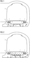
- FIG.1 shows an example and a schematic of an underfloor device carrier with a downward discharge.
- a conventional underfloor device carrier 1 is shown, which is arranged on the underside of a rail vehicle 2 which is located at a station in a tunnel.
- the underfloor device carrier 1 has two laterally arranged supply air intake points 3 through which supply air 7 is sucked into the interior of the underfloor device carrier 1 .
- the subsequently heated exhaust air 6 is blown out on the underside of the underfloor device carrier 1 via an exhaust air outlet opening 4 and is distributed below the rail vehicle 2, with part of the exhaust air 6 flowing into the space between the rail vehicle 2 and the tunnel wall and another part of the exhaust air 6 through the platform gap 8 towards the platform.
- Fig.2 shows an example and schematically an underfloor device carrier according to the invention with a blow-out downwards on a left-hand platform. It is an identical situation as in Fig.1 shown, where however an underfloor device carrier 1 according to the invention is arranged below the rail vehicle 2 . Like the underfloor device carrier according to the prior art, this includes two laterally arranged supply air intake points 3. The exhaust air 6 is discharged via an exhaust air outlet opening 4 on the underside of the underfloor device carrier 1, with an air guiding device 5 being provided, via which the exit direction of the exhaust air 6 can be specified .
- This air guiding device 5 can be implemented in the form of a plurality of air guiding plates, which can each assume at least two positions in relation to the air flow and can thus steer it in certain directions.
- the air baffles of the air guiding device 5 are positioned in such a way that the exhaust air 6 flows in the direction of the tunnel wall, i.e. opposite to the platform, and thus practically no part of the exhaust air 6 passes through the platform gap in the direction of the platform.
- a drive for example an electric motor, a stepper motor or an electromagnet, is provided for moving the air guide plates of the air guide device 5 . Such a drive is not shown to simplify the schematic diagram.
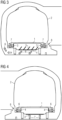
- Fig.3 shows an example and schematically an underfloor device carrier according to the invention with a blow-out downwards on a right-hand platform. It is the embodiment of an underfloor device carrier 1 from Fig.2 shown, with the rail vehicle 2 stopping at a stop with a platform on the right-hand side of the vehicle.
- the air guide plates of the air guide device 5 are positioned in such a way that the exhaust air 6 is blown out on the left-hand side of the vehicle longitudinal axis and thus cannot pass through the platform gap 8 .
- the air baffles of the air guiding device 5 can therefore already be brought into the position required for the next stop while driving or remain in the last position until the next stop.
- the air guide plates of the air guide device 5 can be brought into a neutral central position. This can be particularly advantageous if the lowest flow resistance of the air guiding device 5 occurs in this neutral middle position and the exhaust air 6 thus achieves the greatest possible volume flow while driving.
- FIG.4 shows an example and schematic of an underfloor device carrier with a lateral air outlet.
- a conventional underfloor device carrier 1 is shown, which is arranged on the underside of a rail vehicle 2 which is located at a station in a tunnel.
- the underfloor device carrier 1 has a supply air intake point 3 arranged below, through which supply air 7 is sucked into the interior of the underfloor device carrier 1 .
- the subsequently heated exhaust air 6 is blown out on the sides of the underfloor device carrier 1 via two exhaust air outlet openings 4 .
- a part of the exhaust air 6 flows into the space between the rail vehicle 2 and the tunnel wall, but other part of the exhaust air 6 is blown out directly below the platform gap 8 in the direction of the platform, which is particularly disadvantageous.
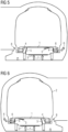
- Fig.5 shows an example and schematically an underfloor device carrier according to the invention with a lateral Blowout on a left-hand platform. It is an identical situation as in Fig.4 shown, but an underfloor device carrier 1 according to the invention is arranged below the rail vehicle 2 . Like the underfloor device carrier according to the prior art, this includes two laterally arranged exhaust air outlet openings 4.
- An air guiding device 5 is provided which includes two flaps, one flap each being assigned to an exhaust air outlet opening 4 and being set up in such a way that they close the respective exhaust air outlet opening 4 can.
- the flaps of the air guiding device 5 can preferably be adjusted independently of one another into an open and a closed position with the aid of a force.
- the outlet direction of the exhaust air 6 can be specified, so that, as in the exemplary embodiment shown, the exhaust air outlet opening 4 on the platform side can be closed and the entire exhaust air 6 exits through the exhaust air outlet opening 4 on the tunnel side.
- a drive for example an electric motor, a stepping motor or an electromagnet, is provided for moving the flaps of the air guiding device 5 . Such a drive is not shown to simplify the schematic diagram.
- Fig.6 shows an example and schematically an underfloor device carrier according to the invention with a lateral blow-out on a right-hand platform. It is the embodiment from Fig.5 shown, wherein during a stop at a platform on the right-hand side, the flaps of the air-guiding device 5 on the right-hand side of the vehicle are closed, so that the exhaust air 6 is blown out at the exhaust-air outlet opening 4 on the tunnel side. It is advisable to close all flaps of the air guiding device 5 while driving open, as this achieves the best cooling effect for the components to be cooled in the underfloor device carrier 1.
- Fig.7 shows, by way of example and schematically, the electrical block diagram of an underfloor device carrier 1 according to the invention.
- the underfloor device carrier 1 comprises a control device 9 which is set up to operate an electric drive 12 .
- This drive 12 acts on an air guiding device 5, so that it is able to place its means for controlling the air flow (flaps or air baffles) in the required position.
- Function monitoring of the air guiding device 5 is provided, in which a position feedback signal 13 is sent from the air guiding device 5 to the control device 9 .
- a malfunction of the drive 12 or of the air guiding device 5 can be detected.
- the control device 9 is connected to a vehicle-side controller 10 by means of a data interface, so that data 11 can be transmitted in both directions between the control device 9 and the vehicle-side controller 10 . Commands can be transmitted to the control device 9 and feedback to the on-board controller 10 via this data interface.
- Fig.8 shows an example and diagrammatically of an underfloor device carrier with a mechanically driven air guiding device.
- a section through an underfloor device carrier 1 is shown, which is arranged on the underside of a rail vehicle 2 .
- the rail vehicle 2 is equipped with a gap bridging in the form of a sliding step 14 which can be actuated by means of a sliding step drive 15 .
- the Underfloor device carrier 1 is after in the Figures 5 and 6 principle shown, according to which alternatively one of two exhaust air outlet openings 4 can be closed.
- the air guiding device 5 is therefore equipped with flaps.
- the sliding step drive 15 acts on the movably mounted step plate and via a power transmission 16 also on the air guiding device 5 and thus moves the flaps.
- This power transmission 16 can be designed, for example, as a Bowden cable, as a hydraulic power transmission, or as a rod drive.
- 8 only one half of the underfloor device carrier 1 is shown, the other half is a mirror image of the first half.
- the other preferred design of an underfloor device carrier 1 with air baffles arranged in the exhaust air flow can also be used with the principle shown.
Landscapes
- Engineering & Computer Science (AREA)
- Mechanical Engineering (AREA)
- Automation & Control Theory (AREA)
- Transportation (AREA)
- Air-Conditioning For Vehicles (AREA)
- Ventilation (AREA)
- Cooling Or The Like Of Electrical Apparatus (AREA)
Description
Die Erfindung betrifft einen Unterflurgeräteträger für ein Schienenfahrzeug.The invention relates to an underfloor device carrier for a rail vehicle.
Unterflurgeräteträger, auch Unterflurcontainer genannt, werden sehr häufig bei Schienenfahrzeugen eingesetzt und dienen der Unterbringung elektrischer Einrichtungen, vorzugsweise von Einrichtungen mit hohem Energiebedarf. Sie bieten den Vorteil, diese elektrischen Einrichtungen getrennt vom Wagenkasten des Schienenfahrzeugs aufbauen und prüfen zu können und sie werden bei der Endmontage des Fahrzeugs unter dem Wagenkasten montiert. Je nach Art der in einem Unterflurcontainer angeordneten elektrischen Einrichtung entsteht eine bestimmte elektrische Verlustleistung, welche typischerweise mittels zwangsbelüfteter Luftkühlung abgeführt wird. Dabei wird an einer Stelle des Unterflurgeräteträgers über einen Luftfilter Umgebungsluft angesaugt, im Inneren des Geräteträgers über wärmeabgebende Oberflächen geleitet und an anderer Stelle wieder an die Umgebung abgegeben. In Abhängigkeit von der zu kühlenden Einrichtung kann die abgegebene Luft jeweils unterschiedlich hohe Temperaturen aufweisen. Einen Extremfall stellen Unterflurgeräte mit Bremswiderständen dar, welche bis zu 700 Grad Celsius erreichen können und einen sehr heißen Abluftstrom bewirken. Ist dies auch bei Fahrt auf freier Strecke unproblematisch, so kann diese Abluft in Haltestellen, insbesondere in Tunneln durchaus zu Problemen führen. Durch den Bahnsteigspalt im Türbereich dringende Abluft stellt für die Passagiere einen Verlust an Komfort dar und kann im extremen Fällen zu Verletzungen führen. Auch muß die in den Passagierraum eindringende warme Abluft gegebenenfalls durch die Klimaanlage in wieder abgekühlt werden. Die Belüftung der zu kühlenden Geräte während des Halts in einer Station abzustellen ist keine akzeptable Option, da beispielsweise Bremswiderstände zu diesem Zeitpunkt den höchsten Kühlbedarf aufweisen. Das Dokument
Das Dokument
Der Erfindung liegt daher die Aufgabe zugrunde, einen Unterflurgeräteträger für ein Schienenfahrzeug anzugeben, welcher die Nachteile des Standes der Technik vermeidet und dabei zu jedem Betriebszeitpunkt die maximal vorgesehene Kühlleistung bzw. Kühlluftstrom bietet.The invention is therefore based on the object of specifying an underfloor device carrier for a rail vehicle which avoids the disadvantages of the prior art and at the same time offers the maximum intended cooling capacity or cooling air flow at any time during operation.
Die Aufgabe wird durch einen Unterflurgeräteträger für ein Schienenfahrzeug mit den Merkmalen des Anspruchs 1 gelöst. Vorteilhafte Ausgestaltungen sind Gegenstand untergeordneter Ansprüche.The object is achieved by an underfloor device carrier for a rail vehicle with the features of
Dem Grundgedanken der Erfindung nach wird ein Unterflurgeräteträger für ein Schienenfahrzeug aufgebaut, welcher eine Zwangsbelüftung mit mindestens einer Zuluftansaugstelle und mindestens einer Abluftauslaßöffnung, umfasst, wobei eine Luftleiteinrichtung vorgesehen ist, welche zwischen mindestens zwei Positionen umschaltbar ist, wobei in einer ersten Position der Luftleiteinrichtung die Abluft in einer ersten Ausströmrichtung ausströmt und in einer zweiten Position der Luftleiteinrichtung die Abluft in einer zweiten Ausströmrichtung ausströmt.According to the basic idea of the invention, an underfloor device carrier for a rail vehicle is constructed, which comprises forced ventilation with at least one supply air intake point and at least one exhaust air outlet opening, with an air guiding device being provided which can be switched between at least two positions, with the exhaust air being released in a first position of the air guiding device flows out in a first outflow direction and in a second position of the air guiding device, the exhaust air flows out in a second outflow direction.
Dadurch ist der Vorteil erzielbar, die Abluft in eine bestimmte Richtung abführen zu können, sodass sie in jene Richtung lenkbar ist, welche zum jeweiligen Zeitpunkt vorteilhaft ist.As a result, the advantage can be achieved of being able to discharge the exhaust air in a specific direction, so that it can be steered in that direction which is advantageous at the respective point in time.
Erfindungsgemäß wird ein Unterflurgeräteträger mit einer Luftkühlung ausgestattet, wobei über mindestens eine Zuluftansaugstelle Umgebungsluft ansaugbar ist, und ein Ausblasen der Kühlluft entweder in einer ersten oder einer zweiten Ausströmrichtung erfolgt. Dazu ist eine Luftleiteinrichtung vorzusehen, welche die entsprechenden Lenkungen des Luftstromes bewirkt. Diese Luftleiteinrichtung kann beispielsweise Klappen umfassen, welche so gesteuert werden, dass sie bestimmte Wege für die Kühlluft freigeben oder verschließen.According to the invention, an underfloor device carrier is equipped with an air cooling system, wherein ambient air can be sucked in via at least one air intake point, and the cooling air is blown out either in a first or a second outflow direction. For this purpose, an air guiding device is to be provided, which effects the corresponding steering of the air flow. This air guiding device can include flaps, for example, which are controlled in such a way that they open or close specific paths for the cooling air.
Die Ausströmrichtungen sind so orientiert, dass sie jeweils in entgegengesetzte Richtungen die Abluft ausblasen. In eingebauter Position des Geräteträgers ist es dadurch möglich, die Abluft quer zur Längsrichtung des Schienenfahrzeugs ausströmen zu lassen, wobei bei einem Halt die Abluft nur an der dem Bahnsteig entgegengesetzten Richtung ausgeblasen wird. Solcherart kann eine Beeinträchtigung des Passagierkomfort durch aus dem Bahnsteigspalt austretende Warmluft verhindert werden, das insbesondere in Tunnels wesentlich ist.The outflow directions are oriented in such a way that they blow out the exhaust air in opposite directions. In the installed position of the device carrier, it is thus possible to let the exhaust air flow out transversely to the longitudinal direction of the rail vehicle, with the exhaust air being blown out only in the opposite direction to the platform when it is stopped. In this way, passenger comfort can be prevented from being impaired by hot air escaping from the platform gap, which is particularly important in tunnels.
Die Ansaugung der Kühlluft erfolgt typischerweise entweder beidseitig (auf die Längsseiten eines Schienenfahrzeugs bezogen) oder von unten, aus Richtung des Gleisbetts. In ersterem Fall erfolgt dabei die Ausblasung der Abluft nach unten, in zweiterem Fall nach beiden Seiten.The cooling air is typically sucked in either on both sides (related to the longitudinal sides of a rail vehicle) or from below, from the direction of the track bed. In In the first case, the exhaust air is blown out downwards, in the second case to both sides.
Diese beiden typischen Ausführungsformen bekannter Unterflurgeräteträger weisen jeweils besonders vorteilhafte Ausprägungen einer Luftleiteinrichtung auf.These two typical embodiments of known underfloor equipment carriers each have particularly advantageous characteristics of an air guiding device.
Ist die Zuluftansaugstelle an der Unterseite des Unterflurgeräteträgers vorgesehen und erfolgt die Ausblasung somit über zwei jeweils seitlich angeordnete Auslaßöffnungen, so empfiehlt es sich Klappen vorzusehen, welche alternativ je eine der Auslaßöffnungen verschließen und den Kühlluftstrom somit nur durch eine der Auslaßöffnungen abzuführen. Bei einem Halt an einem Bahnsteig wird dabei jeweils die bahnsteigseitige Klappe verschlossen, bei Fahrt auf freier Strecke sind beide Klappen zu öffnen und die Abluft somit über beide Auslaßöffnungen abzuführen.If the supply air intake point is on the underside of the underfloor device support and the air is blown out through two laterally arranged outlet openings, it is advisable to provide flaps which alternatively close one of the outlet openings and thus only discharge the cooling air flow through one of the outlet openings. When stopping at a platform, the platform-side flap is closed in each case, when driving on the open route both flaps are to be opened and the exhaust air is thus discharged via both outlet openings.
Bei Unterflurgeräteträgern mit seitlichen Zuluftansaugstellen und nach unten gerichteter Auslaßöffnung ist es empfehlenswert, die ausströmende Luft mit einer Querkomponente der Geschwindigkeit zu versehen, d.h. sie gerichtet auf eine Seite (bezogen auf das Schienenfahrzeug) ausströmen zu lassen. Dazu können beispielsweise Luftleitbleche vorgesehen werden, welche schwenkbar in dem Luftstrom angeordnet werden und den Luftstrom somit gerichtet austreten lassen.In the case of underfloor equipment carriers with lateral air intake points and outlet openings pointing downwards, it is advisable to provide the outflowing air with a transverse velocity component, i.e. let it flow out directed to one side (relative to the rail vehicle). For this purpose, for example, air baffles can be provided, which are pivotably arranged in the air flow and thus allow the air flow to exit in a directed manner.
Eine andere Ausführungsform sieht vor, die Auslaßöffnung so zu gestalten, dass sie zwei Arten von Auslaßkanälen aufweist, welche jeweils die Abluft in eine Richtung leiten, und in Abhängigkeit von der gewünschten Auslaßrichtung jeweils eine Art der Auslaßkanäle zu verschließen.Another embodiment provides for the outlet opening to be designed in such a way that it has two types of outlet channels, each of which directs the exhaust air in one direction, and to close one type of outlet channel in each case depending on the desired outlet direction.
In weiterer Fortbildung der Erfindung ist es vorteilhaft, die Luftleiteinrichtung während der Fahrt in eine solche Position zu stellen, welche den geringsten Strömungswiderstand für die Kühlluft bildet und somit die Kühlwirkung maximiert.In a further development of the invention, it is advantageous to place the air guiding device in such a position while driving that forms the lowest flow resistance for the cooling air and thus maximizes the cooling effect.
Die eine Ausführungsform der Erfindung sieht vor, dass die Steuerung der Luftleiteinrichtung vorzugsweise automatisch und mittels eines elektrischen Antriebs erfolgt. Es ist dafür beispielsweise eine Steuerung vorzusehen, welche von fahrzeugseitigen Einrichtungen (z.B. Türsteuerung oder Fahrzeugsteuerung) Informationen über die zu wählende Ausblasseite erhält, welche an der aktuell angefahrenen Haltestelle erforderlich ist. Diese Steuerung umfasst die zum Antrieb der Luftleiteinrichtung erforderliche Leistungselektronik und optional Mittel zur Erfassung des Betriebszustandes der zugeordneten Antriebe sowie zur Erfassung von Fehlern in diesen Komponenten. Es ist besonders vorteilhaft, eine bidirektionale Datenschnittstelle vorzusehen, über welche Befehle von fahrzeugseitigen Einrichtungen an die Steuereinrichtung und Status- bzw. Fehlermeldungen an die fahrzeugseitigen Einrichtungen übermittelbar sind.One embodiment of the invention provides that the air guiding device is preferably controlled automatically and by means of an electric drive. For this purpose, for example, a controller must be provided which receives information from vehicle-mounted devices (e.g. door controller or vehicle controller) about the exhaust side to be selected, which is required at the stop currently being approached. This controller includes the power electronics required to drive the air guiding device and optionally means for detecting the operating state of the associated drives and for detecting errors in these components. It is particularly advantageous to provide a bidirectional data interface via which commands from on-board devices can be transmitted to the control device and status or error messages can be transmitted to the on-board devices.
Die andere Ausführungsform der Erfindung sieht vor, dass die Luftleiteinrichtung unmittelbar mechanisch von einem Türantrieb oder einem Antrieb einer Spaltüberbrückung betätigt wird.The other embodiment of the invention provides that the air guiding device is directly actuated mechanically by a door drive or a drive for bridging a gap.
Da an einer Haltestelle in den überwiegenden Fällen nur die Türen einer Fahrzeugseite geöffnet werden, kann ein Tür- oder Spaltüberbrückungsantrieb gleichzeitig mit der Tür oder der Spaltüberbrückung auch die Luftleiteinrichtung eines Unterflurgeräteträgers antreiben. Es ist besonders vorteilhaft, dabei den Antrieb einer Spaltüberbrückung zu verwenden, da dieser vor dem Öffnen der Tür und nach dem Schließen der Tür wirkt, sodass die Luftleiteinrichtung vor dem Öffnen der Tür jedenfalls in die jeweils richtige Position gestellt wird. Die Übertragung der Antriebskraft auf die Luftleiteinrichtung kann dabei beispielsweise mittels eines Bowdenzuges erfolgen.Since in most cases only the doors on one side of the vehicle are opened at a stop, a door or gap bridging drive can also drive the air deflector of an underfloor device carrier at the same time as the door or the gap bridging. It is particularly advantageous to use the drive of a gap bridging, since this acts before opening the door and after closing the door, so that the In any case, the air guiding device is placed in the correct position before the door is opened. The drive force can be transmitted to the air guiding device, for example, by means of a Bowden cable.
Andere Ausprägungen einer variablen Kühlluftausblasung eines Unterflurgeräteträgers sind, jedoch mit verminderter Effizienz und höheren Herstellkosten, auch realisierbar. Beispielsweise können für jede Ausblasrichtung eigene Ventilatoren und zugehörige Luftwege zu einer jeweiligen Abluftauslaßöffnung vorgesehen werden, was zwar keine variable Luftleiteinrichtung erforderlich macht, den Herstellaufwand jedoch erhöht.Other forms of variable cooling air blow-out of an underfloor device carrier can also be implemented, but with reduced efficiency and higher production costs. For example, separate fans and associated air paths to a respective exhaust air outlet opening can be provided for each blow-out direction, which does not require a variable air guide device, but increases the manufacturing cost.
Eine andere Möglichkeit sieht vor, den Kühlluftventilator umsteuerbar auszuführen, sodass die Zuluftansaugstelle und die Abluftauslaßöffnung ihre Funktion beliebig tauschen können. Dies ist jedoch nicht vorteilhaft, da herkömmliche Ventilatoren nur in eine Luftförderrichtung eine hohe Effizienz besitzen, in der entgegensetzen Richtung ist diese meist äußerst gering. Dies wäre nur durch den Einsatz von aufwendigen Ventilatoren mit Schaufelverstellung lösbar.Another possibility provides for the cooling air fan to be designed to be reversible, so that the supply air intake point and the exhaust air outlet opening can exchange their function as desired. However, this is not advantageous since conventional fans only have a high level of efficiency in one air conveying direction, and this is usually extremely low in the opposite direction. This could only be solved by using expensive fans with blade adjustment.
Es zeigen beispielhaft:
-
Fig.1 Unterflurgeräteträger, Ausblasung nach unten. -
Fig.2 Unterflurgeräteträger, Ausblasung nach unten, Bahnsteig links. -
Fig.3 Unterflurgeräteträger, Ausblasung nach unten, Bahnsteig rechts. -
Fig.4 Unterflurgeräteträger, Ausblasung seitlich. -
Fig.5 Unterflurgeräteträger, Ausblasung seitlich, Bahnsteig links. -
Fig.5 Unterflurgeräteträger, Ausblasung seitlich, Bahnsteig rechts. -
Fig.7 Unterflurgeräteträger, elektrisches Blockschaltbild. -
Fig.8 Unterflurgeräteträger, mechanisch angetriebene Luftleiteinrichtung.
-
Fig.1 Underfloor device carrier, air discharge downwards. -
Fig.2 Underfloor equipment carrier, air discharge downwards, platform on the left. -
Fig.3 Underfloor equipment carrier, air discharge downwards, platform on the right. -
Fig.4 Underfloor device carrier, lateral air discharge. -
Fig.5 Underfloor equipment carrier, lateral blow-out, platform on the left. -
Fig.5 Underfloor equipment carrier, side discharge, platform on the right. -
Fig.7 Underfloor device carrier, electrical block diagram. -
Fig.8 Underfloor equipment carrier, mechanically driven air deflector.
- 11
- Unterflurgeräteträgerunderfloor equipment carrier
- 22
- Schienenfahrzeugrail vehicle
- 33
- Zuluftansaugstellesupply air intake point
- 44
- Abluftauslaßöffnungexhaust outlet opening
- 55
- Luftleiteinrichtungair deflector
- 66
- Abluftexhaust air
- 77
- Zuluftsupply air
- 88th
- Bahnsteigspaltplatform gap
- 99
- Steuereinrichtungcontrol device
- 1010
- Fahrzeugseitige SteuerungVehicle control
- 1111
- DatenData
- 1212
- Antriebdrive
- 1313
- Stellungsrückmeldesignalposition feedback signal
- 1414
- Schiebetrittsliding step
- 1515
- Schiebetrittantriebsliding step drive
- 1616
- Kraftübertragungpower transmission
Claims (4)
- Underfloor equipment carrier (1) for a rail vehicle (2), comprising a forced-ventilation system with at least one supply-air intake point (3) and at least one discharge-air outlet opening (4), and an air-guiding device (5) which is switchable between at least two positions, wherein, in a first position of the air-guiding device (5), the discharge air (6) flows out in a first outflow direction and, in a second position of the air-guiding device (5), the discharge air (6) flows out in a second outflow direction, wherein the first outflow direction and the second outflow direction are oriented oppositely in relation to one another, wherein, in the installation position of the underfloor equipment carrier (1), the first outflow direction and the second outflow direction are in each case oriented transversely to the longitudinal direction of a rail vehicle, wherein provision is made of an electric drive (12) for actuating the air-guiding device (5), or the actuation of the air-guiding device (5) is realized by a means for transmission of force (16) guided into the underfloor equipment carrier (1) from the outside.
- Underfloor equipment carrier (1) for a rail vehicle (2) according to Claim 1,
characterized in that the air-guiding device (5) comprises two flaps which, in a manner dependent on the respective outflow direction, in each case open up or close off an associated discharge-air outlet opening (4). - Underfloor equipment carrier (1) for a rail vehicle (2) according to Claim 1,
characterized in that the air-guiding device (5) comprises at least one air-guiding plate which, in a manner dependent on the respective required outflow direction, is moved into a specific position. - Underfloor equipment carrier (1) for a rail vehicle (2) according to one of Claims 1 to 3,
characterized in that the underfloor equipment carrier (1) comprises a control device (9) which is configured for transfer of data (11) with a vehicle-side controller (10) arranged outside the underfloor equipment carrier (1) and which comprises means for controlling the drive (12) .
Applications Claiming Priority (2)
| Application Number | Priority Date | Filing Date | Title |
|---|---|---|---|
| ATA50188/2018A AT521090B1 (en) | 2018-03-07 | 2018-03-07 | Underfloor device carrier for a rail vehicle |
| PCT/EP2019/055318 WO2019170602A1 (en) | 2018-03-07 | 2019-03-04 | Underfloor device carrier for a rail vehicle |
Publications (2)
| Publication Number | Publication Date |
|---|---|
| EP3740407A1 EP3740407A1 (en) | 2020-11-25 |
| EP3740407B1 true EP3740407B1 (en) | 2023-04-26 |
Family
ID=65729324
Family Applications (1)
| Application Number | Title | Priority Date | Filing Date |
|---|---|---|---|
| EP19710351.8A Active EP3740407B1 (en) | 2018-03-07 | 2019-03-04 | Underfloor device carrier for a rail vehicle |
Country Status (4)
| Country | Link |
|---|---|
| EP (1) | EP3740407B1 (en) |
| CN (1) | CN111867913B (en) |
| AT (1) | AT521090B1 (en) |
| WO (1) | WO2019170602A1 (en) |
Families Citing this family (3)
| Publication number | Priority date | Publication date | Assignee | Title |
|---|---|---|---|---|
| DE102019216838B3 (en) * | 2019-10-31 | 2021-02-18 | Siemens Mobility GmbH | Vehicle with an air outlet opening |
| CN111762217A (en) * | 2020-05-29 | 2020-10-13 | 中车青岛四方机车车辆股份有限公司 | Undercarriage Layout Structure and Rail Vehicle |
| CN111762218A (en) * | 2020-05-29 | 2020-10-13 | 中车青岛四方机车车辆股份有限公司 | rail vehicle |
Family Cites Families (7)
| Publication number | Priority date | Publication date | Assignee | Title |
|---|---|---|---|---|
| CN2055455U (en) * | 1989-11-06 | 1990-04-04 | 陈白光 | Strong exhauster for carriage |
| DE4223647C2 (en) * | 1992-07-17 | 1995-04-13 | Siemens Ag | Device for cooling electronic units of a power supply system for passenger cars |
| DE19632053C2 (en) * | 1996-08-08 | 2000-10-05 | Voith Turbo Beteiligungs Gmbh | Underfloor cooling system and method for cooling electrical power components in rail vehicles |
| DE19824461A1 (en) * | 1998-05-30 | 1999-12-02 | Behr Industrietech Gmbh & Co | Ready-to-install air conditioning module, especially for rail vehicles |
| CN203111186U (en) * | 2012-09-30 | 2013-08-07 | 成都飞机工业(集团)有限责任公司 | Ventilating grill for high-speed vehicle system equipment area |
| DE102013210053B3 (en) * | 2013-05-29 | 2014-09-11 | Faurecia Innenraum Systeme Gmbh | air vents |
| DE102015202815A1 (en) * | 2015-02-17 | 2016-08-18 | Mahle International Gmbh | Rail vehicle with cooling system |
-
2018
- 2018-03-07 AT ATA50188/2018A patent/AT521090B1/en not_active IP Right Cessation
-
2019
- 2019-03-04 WO PCT/EP2019/055318 patent/WO2019170602A1/en not_active Ceased
- 2019-03-04 CN CN201980017729.0A patent/CN111867913B/en active Active
- 2019-03-04 EP EP19710351.8A patent/EP3740407B1/en active Active
Also Published As
| Publication number | Publication date |
|---|---|
| AT521090A1 (en) | 2019-10-15 |
| WO2019170602A1 (en) | 2019-09-12 |
| EP3740407A1 (en) | 2020-11-25 |
| AT521090B1 (en) | 2020-04-15 |
| CN111867913B (en) | 2024-03-22 |
| CN111867913A (en) | 2020-10-30 |
Similar Documents
| Publication | Publication Date | Title |
|---|---|---|
| EP3740407B1 (en) | Underfloor device carrier for a rail vehicle | |
| EP2987670B1 (en) | Apparatus for tuning an air flow | |
| EP3041696B1 (en) | System having a control unit | |
| EP3530505B1 (en) | Air vent | |
| DE102013214335A1 (en) | Railway vehicle | |
| EP0354163B1 (en) | Heating device for automobile vehicle | |
| DE102013214310A1 (en) | Railway vehicle | |
| EP1457371B1 (en) | Air outlet, in particular for vehicles | |
| DE102015207442A1 (en) | Vehicle with a vehicle component to be cooled | |
| WO2005068231A1 (en) | Actuating device and heating or air conditioning unit | |
| DE102013108655B3 (en) | Air nozzle for guiding air flow from air feed chute or air supply line to e.g. heater, in passenger compartment of motor car, has electromotors coupled with slats of slat blocks through drive units | |
| DE102016013353A1 (en) | Outlets for a motor vehicle and associated motor vehicle | |
| DE102021127707A1 (en) | Air conditioning with focused air supply | |
| EP3953212B1 (en) | Air-conditioning arrangement for a vehicle, and vehicle | |
| DE202018104362U1 (en) | Closing device with lamellae for intake or outlet openings of the process air of air conditioning and ventilation devices for rail vehicles | |
| WO2016041549A1 (en) | Device for combined pressure-protection and air-flow control in the interior of high-speed rail vehicles | |
| EP3986765B1 (en) | System for cooling technical units in a rail vehicle | |
| EP1502782B1 (en) | Device for regulating the flow rate of a fluid in a conduit | |
| DE102016218456A1 (en) | Air outlet device for directionally controlled supply of air in a vehicle interior | |
| EP0444551A2 (en) | Housing for a ventilator in a vehicle heating or air conditioning system | |
| EP4281302B1 (en) | Air discharge device for supplying temperature-controlled air for an interior of a motor vehicle | |
| EP1002677A1 (en) | Heating and/or air conditioning unit for a vehicle | |
| EP1555148B1 (en) | Air conditioning device, in particular for a vehicle | |
| DE1530055C3 (en) | ||
| DE2352479A1 (en) | EQUIPMENT SWITCHABLE TO HEATING, VENTILATION OR AIR CONDITIONING OPERATION |
Legal Events
| Date | Code | Title | Description |
|---|---|---|---|
| STAA | Information on the status of an ep patent application or granted ep patent |
Free format text: STATUS: UNKNOWN |
|
| STAA | Information on the status of an ep patent application or granted ep patent |
Free format text: STATUS: THE INTERNATIONAL PUBLICATION HAS BEEN MADE |
|
| PUAI | Public reference made under article 153(3) epc to a published international application that has entered the european phase |
Free format text: ORIGINAL CODE: 0009012 |
|
| STAA | Information on the status of an ep patent application or granted ep patent |
Free format text: STATUS: REQUEST FOR EXAMINATION WAS MADE |
|
| 17P | Request for examination filed |
Effective date: 20200819 |
|
| AK | Designated contracting states |
Kind code of ref document: A1 Designated state(s): AL AT BE BG CH CY CZ DE DK EE ES FI FR GB GR HR HU IE IS IT LI LT LU LV MC MK MT NL NO PL PT RO RS SE SI SK SM TR |
|
| AX | Request for extension of the european patent |
Extension state: BA ME |
|
| DAV | Request for validation of the european patent (deleted) | ||
| DAX | Request for extension of the european patent (deleted) | ||
| STAA | Information on the status of an ep patent application or granted ep patent |
Free format text: STATUS: EXAMINATION IS IN PROGRESS |
|
| 17Q | First examination report despatched |
Effective date: 20210920 |
|
| GRAP | Despatch of communication of intention to grant a patent |
Free format text: ORIGINAL CODE: EPIDOSNIGR1 |
|
| STAA | Information on the status of an ep patent application or granted ep patent |
Free format text: STATUS: GRANT OF PATENT IS INTENDED |
|
| INTG | Intention to grant announced |
Effective date: 20221028 |
|
| GRAS | Grant fee paid |
Free format text: ORIGINAL CODE: EPIDOSNIGR3 |
|
| GRAA | (expected) grant |
Free format text: ORIGINAL CODE: 0009210 |
|
| STAA | Information on the status of an ep patent application or granted ep patent |
Free format text: STATUS: THE PATENT HAS BEEN GRANTED |
|
| AK | Designated contracting states |
Kind code of ref document: B1 Designated state(s): AL AT BE BG CH CY CZ DE DK EE ES FI FR GB GR HR HU IE IS IT LI LT LU LV MC MK MT NL NO PL PT RO RS SE SI SK SM TR |
|
| REG | Reference to a national code |
Ref country code: GB Ref legal event code: FG4D Free format text: NOT ENGLISH |
|
| REG | Reference to a national code |
Ref country code: CH Ref legal event code: EP |
|
| REG | Reference to a national code |
Ref country code: DE Ref legal event code: R096 Ref document number: 502019007559 Country of ref document: DE |
|
| REG | Reference to a national code |
Ref country code: AT Ref legal event code: REF Ref document number: 1562628 Country of ref document: AT Kind code of ref document: T Effective date: 20230515 |
|
| REG | Reference to a national code |
Ref country code: IE Ref legal event code: FG4D Free format text: LANGUAGE OF EP DOCUMENT: GERMAN |
|
| REG | Reference to a national code |
Ref country code: SE Ref legal event code: TRGR |
|
| REG | Reference to a national code |
Ref country code: LT Ref legal event code: MG9D |
|
| REG | Reference to a national code |
Ref country code: NL Ref legal event code: MP Effective date: 20230426 |
|
| PG25 | Lapsed in a contracting state [announced via postgrant information from national office to epo] |
Ref country code: NL Free format text: LAPSE BECAUSE OF FAILURE TO SUBMIT A TRANSLATION OF THE DESCRIPTION OR TO PAY THE FEE WITHIN THE PRESCRIBED TIME-LIMIT Effective date: 20230426 |
|
| PG25 | Lapsed in a contracting state [announced via postgrant information from national office to epo] |
Ref country code: PT Free format text: LAPSE BECAUSE OF FAILURE TO SUBMIT A TRANSLATION OF THE DESCRIPTION OR TO PAY THE FEE WITHIN THE PRESCRIBED TIME-LIMIT Effective date: 20230828 Ref country code: NO Free format text: LAPSE BECAUSE OF FAILURE TO SUBMIT A TRANSLATION OF THE DESCRIPTION OR TO PAY THE FEE WITHIN THE PRESCRIBED TIME-LIMIT Effective date: 20230726 Ref country code: ES Free format text: LAPSE BECAUSE OF FAILURE TO SUBMIT A TRANSLATION OF THE DESCRIPTION OR TO PAY THE FEE WITHIN THE PRESCRIBED TIME-LIMIT Effective date: 20230426 |
|
| PG25 | Lapsed in a contracting state [announced via postgrant information from national office to epo] |
Ref country code: RS Free format text: LAPSE BECAUSE OF FAILURE TO SUBMIT A TRANSLATION OF THE DESCRIPTION OR TO PAY THE FEE WITHIN THE PRESCRIBED TIME-LIMIT Effective date: 20230426 Ref country code: PL Free format text: LAPSE BECAUSE OF FAILURE TO SUBMIT A TRANSLATION OF THE DESCRIPTION OR TO PAY THE FEE WITHIN THE PRESCRIBED TIME-LIMIT Effective date: 20230426 Ref country code: LV Free format text: LAPSE BECAUSE OF FAILURE TO SUBMIT A TRANSLATION OF THE DESCRIPTION OR TO PAY THE FEE WITHIN THE PRESCRIBED TIME-LIMIT Effective date: 20230426 Ref country code: LT Free format text: LAPSE BECAUSE OF FAILURE TO SUBMIT A TRANSLATION OF THE DESCRIPTION OR TO PAY THE FEE WITHIN THE PRESCRIBED TIME-LIMIT Effective date: 20230426 Ref country code: IS Free format text: LAPSE BECAUSE OF FAILURE TO SUBMIT A TRANSLATION OF THE DESCRIPTION OR TO PAY THE FEE WITHIN THE PRESCRIBED TIME-LIMIT Effective date: 20230826 Ref country code: HR Free format text: LAPSE BECAUSE OF FAILURE TO SUBMIT A TRANSLATION OF THE DESCRIPTION OR TO PAY THE FEE WITHIN THE PRESCRIBED TIME-LIMIT Effective date: 20230426 Ref country code: GR Free format text: LAPSE BECAUSE OF FAILURE TO SUBMIT A TRANSLATION OF THE DESCRIPTION OR TO PAY THE FEE WITHIN THE PRESCRIBED TIME-LIMIT Effective date: 20230727 |
|
| PG25 | Lapsed in a contracting state [announced via postgrant information from national office to epo] |
Ref country code: FI Free format text: LAPSE BECAUSE OF FAILURE TO SUBMIT A TRANSLATION OF THE DESCRIPTION OR TO PAY THE FEE WITHIN THE PRESCRIBED TIME-LIMIT Effective date: 20230426 |
|
| PG25 | Lapsed in a contracting state [announced via postgrant information from national office to epo] |
Ref country code: SK Free format text: LAPSE BECAUSE OF FAILURE TO SUBMIT A TRANSLATION OF THE DESCRIPTION OR TO PAY THE FEE WITHIN THE PRESCRIBED TIME-LIMIT Effective date: 20230426 |
|
| REG | Reference to a national code |
Ref country code: DE Ref legal event code: R097 Ref document number: 502019007559 Country of ref document: DE |
|
| PG25 | Lapsed in a contracting state [announced via postgrant information from national office to epo] |
Ref country code: SM Free format text: LAPSE BECAUSE OF FAILURE TO SUBMIT A TRANSLATION OF THE DESCRIPTION OR TO PAY THE FEE WITHIN THE PRESCRIBED TIME-LIMIT Effective date: 20230426 Ref country code: SK Free format text: LAPSE BECAUSE OF FAILURE TO SUBMIT A TRANSLATION OF THE DESCRIPTION OR TO PAY THE FEE WITHIN THE PRESCRIBED TIME-LIMIT Effective date: 20230426 Ref country code: RO Free format text: LAPSE BECAUSE OF FAILURE TO SUBMIT A TRANSLATION OF THE DESCRIPTION OR TO PAY THE FEE WITHIN THE PRESCRIBED TIME-LIMIT Effective date: 20230426 Ref country code: EE Free format text: LAPSE BECAUSE OF FAILURE TO SUBMIT A TRANSLATION OF THE DESCRIPTION OR TO PAY THE FEE WITHIN THE PRESCRIBED TIME-LIMIT Effective date: 20230426 Ref country code: DK Free format text: LAPSE BECAUSE OF FAILURE TO SUBMIT A TRANSLATION OF THE DESCRIPTION OR TO PAY THE FEE WITHIN THE PRESCRIBED TIME-LIMIT Effective date: 20230426 |
|
| PLBE | No opposition filed within time limit |
Free format text: ORIGINAL CODE: 0009261 |
|
| STAA | Information on the status of an ep patent application or granted ep patent |
Free format text: STATUS: NO OPPOSITION FILED WITHIN TIME LIMIT |
|
| 26N | No opposition filed |
Effective date: 20240129 |
|
| PG25 | Lapsed in a contracting state [announced via postgrant information from national office to epo] |
Ref country code: SI Free format text: LAPSE BECAUSE OF FAILURE TO SUBMIT A TRANSLATION OF THE DESCRIPTION OR TO PAY THE FEE WITHIN THE PRESCRIBED TIME-LIMIT Effective date: 20230426 |
|
| PG25 | Lapsed in a contracting state [announced via postgrant information from national office to epo] |
Ref country code: SI Free format text: LAPSE BECAUSE OF FAILURE TO SUBMIT A TRANSLATION OF THE DESCRIPTION OR TO PAY THE FEE WITHIN THE PRESCRIBED TIME-LIMIT Effective date: 20230426 Ref country code: IT Free format text: LAPSE BECAUSE OF FAILURE TO SUBMIT A TRANSLATION OF THE DESCRIPTION OR TO PAY THE FEE WITHIN THE PRESCRIBED TIME-LIMIT Effective date: 20230426 |
|
| PG25 | Lapsed in a contracting state [announced via postgrant information from national office to epo] |
Ref country code: BG Free format text: LAPSE BECAUSE OF FAILURE TO SUBMIT A TRANSLATION OF THE DESCRIPTION OR TO PAY THE FEE WITHIN THE PRESCRIBED TIME-LIMIT Effective date: 20230426 |
|
| PG25 | Lapsed in a contracting state [announced via postgrant information from national office to epo] |
Ref country code: LU Free format text: LAPSE BECAUSE OF NON-PAYMENT OF DUE FEES Effective date: 20240304 |
|
| PG25 | Lapsed in a contracting state [announced via postgrant information from national office to epo] |
Ref country code: MC Free format text: LAPSE BECAUSE OF FAILURE TO SUBMIT A TRANSLATION OF THE DESCRIPTION OR TO PAY THE FEE WITHIN THE PRESCRIBED TIME-LIMIT Effective date: 20230426 |
|
| PG25 | Lapsed in a contracting state [announced via postgrant information from national office to epo] |
Ref country code: MC Free format text: LAPSE BECAUSE OF FAILURE TO SUBMIT A TRANSLATION OF THE DESCRIPTION OR TO PAY THE FEE WITHIN THE PRESCRIBED TIME-LIMIT Effective date: 20230426 Ref country code: LU Free format text: LAPSE BECAUSE OF NON-PAYMENT OF DUE FEES Effective date: 20240304 Ref country code: BG Free format text: LAPSE BECAUSE OF FAILURE TO SUBMIT A TRANSLATION OF THE DESCRIPTION OR TO PAY THE FEE WITHIN THE PRESCRIBED TIME-LIMIT Effective date: 20230426 |
|
| REG | Reference to a national code |
Ref country code: BE Ref legal event code: MM Effective date: 20240331 |
|
| PG25 | Lapsed in a contracting state [announced via postgrant information from national office to epo] |
Ref country code: BE Free format text: LAPSE BECAUSE OF NON-PAYMENT OF DUE FEES Effective date: 20240331 |
|
| PG25 | Lapsed in a contracting state [announced via postgrant information from national office to epo] |
Ref country code: IE Free format text: LAPSE BECAUSE OF NON-PAYMENT OF DUE FEES Effective date: 20240304 |
|
| PG25 | Lapsed in a contracting state [announced via postgrant information from national office to epo] |
Ref country code: IE Free format text: LAPSE BECAUSE OF NON-PAYMENT OF DUE FEES Effective date: 20240304 Ref country code: BE Free format text: LAPSE BECAUSE OF NON-PAYMENT OF DUE FEES Effective date: 20240331 |
|
| PGFP | Annual fee paid to national office [announced via postgrant information from national office to epo] |
Ref country code: DE Payment date: 20250520 Year of fee payment: 7 |
|
| PGFP | Annual fee paid to national office [announced via postgrant information from national office to epo] |
Ref country code: GB Payment date: 20250403 Year of fee payment: 7 |
|
| PGFP | Annual fee paid to national office [announced via postgrant information from national office to epo] |
Ref country code: CH Payment date: 20250611 Year of fee payment: 7 |
|
| PG25 | Lapsed in a contracting state [announced via postgrant information from national office to epo] |
Ref country code: CY Free format text: LAPSE BECAUSE OF FAILURE TO SUBMIT A TRANSLATION OF THE DESCRIPTION OR TO PAY THE FEE WITHIN THE PRESCRIBED TIME-LIMIT; INVALID AB INITIO Effective date: 20190304 |
|
| PG25 | Lapsed in a contracting state [announced via postgrant information from national office to epo] |
Ref country code: HU Free format text: LAPSE BECAUSE OF FAILURE TO SUBMIT A TRANSLATION OF THE DESCRIPTION OR TO PAY THE FEE WITHIN THE PRESCRIBED TIME-LIMIT; INVALID AB INITIO Effective date: 20190304 |
|
| PG25 | Lapsed in a contracting state [announced via postgrant information from national office to epo] |
Ref country code: TR Free format text: LAPSE BECAUSE OF FAILURE TO SUBMIT A TRANSLATION OF THE DESCRIPTION OR TO PAY THE FEE WITHIN THE PRESCRIBED TIME-LIMIT Effective date: 20230426 |
|
| PGFP | Annual fee paid to national office [announced via postgrant information from national office to epo] |
Ref country code: SE Payment date: 20260305 Year of fee payment: 8 |
|
| PGFP | Annual fee paid to national office [announced via postgrant information from national office to epo] |
Ref country code: AT Payment date: 20260206 Year of fee payment: 8 |
|
| PGFP | Annual fee paid to national office [announced via postgrant information from national office to epo] |
Ref country code: FR Payment date: 20260316 Year of fee payment: 8 |
|
| PGFP | Annual fee paid to national office [announced via postgrant information from national office to epo] |
Ref country code: CZ Payment date: 20260225 Year of fee payment: 8 |