EP3740342B1 - Conveyor belt assembly - Google Patents
Conveyor belt assembly Download PDFInfo
- Publication number
- EP3740342B1 EP3740342B1 EP19700443.5A EP19700443A EP3740342B1 EP 3740342 B1 EP3740342 B1 EP 3740342B1 EP 19700443 A EP19700443 A EP 19700443A EP 3740342 B1 EP3740342 B1 EP 3740342B1
- Authority
- EP
- European Patent Office
- Prior art keywords
- conveyor belt
- section
- conveying
- belt assembly
- support devices
- Prior art date
- Legal status (The legal status is an assumption and is not a legal conclusion. Google has not performed a legal analysis and makes no representation as to the accuracy of the status listed.)
- Active
Links
Images




Classifications
-
- B—PERFORMING OPERATIONS; TRANSPORTING
- B65—CONVEYING; PACKING; STORING; HANDLING THIN OR FILAMENTARY MATERIAL
- B65G—TRANSPORT OR STORAGE DEVICES, e.g. CONVEYORS FOR LOADING OR TIPPING, SHOP CONVEYOR SYSTEMS OR PNEUMATIC TUBE CONVEYORS
- B65G17/00—Conveyors having an endless traction element, e.g. a chain, transmitting movement to a continuous or substantially-continuous load-carrying surface or to a series of individual load-carriers; Endless-chain conveyors in which the chains form the load-carrying surface
- B65G17/06—Conveyors having an endless traction element, e.g. a chain, transmitting movement to a continuous or substantially-continuous load-carrying surface or to a series of individual load-carriers; Endless-chain conveyors in which the chains form the load-carrying surface having a load-carrying surface formed by a series of interconnected, e.g. longitudinal, links, plates, or platforms
- B65G17/065—Conveyors having an endless traction element, e.g. a chain, transmitting movement to a continuous or substantially-continuous load-carrying surface or to a series of individual load-carriers; Endless-chain conveyors in which the chains form the load-carrying surface having a load-carrying surface formed by a series of interconnected, e.g. longitudinal, links, plates, or platforms the load carrying surface being formed by plates or platforms attached to a single traction element
-
- B—PERFORMING OPERATIONS; TRANSPORTING
- B23—MACHINE TOOLS; METAL-WORKING NOT OTHERWISE PROVIDED FOR
- B23K—SOLDERING OR UNSOLDERING; WELDING; CLADDING OR PLATING BY SOLDERING OR WELDING; CUTTING BY APPLYING HEAT LOCALLY, e.g. FLAME CUTTING; WORKING BY LASER BEAM
- B23K26/00—Working by laser beam, e.g. welding, cutting or boring
- B23K26/08—Devices involving relative movement between laser beam and workpiece
- B23K26/083—Devices involving movement of the workpiece in at least one axial direction
- B23K26/0838—Devices involving movement of the workpiece in at least one axial direction by using an endless conveyor belt
-
- B—PERFORMING OPERATIONS; TRANSPORTING
- B23—MACHINE TOOLS; METAL-WORKING NOT OTHERWISE PROVIDED FOR
- B23K—SOLDERING OR UNSOLDERING; WELDING; CLADDING OR PLATING BY SOLDERING OR WELDING; CUTTING BY APPLYING HEAT LOCALLY, e.g. FLAME CUTTING; WORKING BY LASER BEAM
- B23K26/00—Working by laser beam, e.g. welding, cutting or boring
- B23K26/36—Removing material
- B23K26/38—Removing material by boring or cutting
-
- B—PERFORMING OPERATIONS; TRANSPORTING
- B23—MACHINE TOOLS; METAL-WORKING NOT OTHERWISE PROVIDED FOR
- B23K—SOLDERING OR UNSOLDERING; WELDING; CLADDING OR PLATING BY SOLDERING OR WELDING; CUTTING BY APPLYING HEAT LOCALLY, e.g. FLAME CUTTING; WORKING BY LASER BEAM
- B23K37/00—Auxiliary devices or processes, not specially adapted for a procedure covered by only one of the other main groups of this subclass
- B23K37/04—Auxiliary devices or processes, not specially adapted for a procedure covered by only one of the other main groups of this subclass for holding or positioning work
- B23K37/0408—Auxiliary devices or processes, not specially adapted for a procedure covered by only one of the other main groups of this subclass for holding or positioning work for planar work
-
- B—PERFORMING OPERATIONS; TRANSPORTING
- B65—CONVEYING; PACKING; STORING; HANDLING THIN OR FILAMENTARY MATERIAL
- B65G—TRANSPORT OR STORAGE DEVICES, e.g. CONVEYORS FOR LOADING OR TIPPING, SHOP CONVEYOR SYSTEMS OR PNEUMATIC TUBE CONVEYORS
- B65G15/00—Conveyors having endless load-conveying surfaces, i.e. belts and like continuous members, to which tractive effort is transmitted by means other than endless driving elements of similar configuration
- B65G15/10—Conveyors having endless load-conveying surfaces, i.e. belts and like continuous members, to which tractive effort is transmitted by means other than endless driving elements of similar configuration comprising two or more co-operating endless surfaces with parallel longitudinal axes, or a multiplicity of parallel elements, e.g. ropes defining an endless surface
- B65G15/12—Conveyors having endless load-conveying surfaces, i.e. belts and like continuous members, to which tractive effort is transmitted by means other than endless driving elements of similar configuration comprising two or more co-operating endless surfaces with parallel longitudinal axes, or a multiplicity of parallel elements, e.g. ropes defining an endless surface with two or more endless belts
-
- B—PERFORMING OPERATIONS; TRANSPORTING
- B65—CONVEYING; PACKING; STORING; HANDLING THIN OR FILAMENTARY MATERIAL
- B65G—TRANSPORT OR STORAGE DEVICES, e.g. CONVEYORS FOR LOADING OR TIPPING, SHOP CONVEYOR SYSTEMS OR PNEUMATIC TUBE CONVEYORS
- B65G15/00—Conveyors having endless load-conveying surfaces, i.e. belts and like continuous members, to which tractive effort is transmitted by means other than endless driving elements of similar configuration
- B65G15/30—Belts or like endless load-carriers
- B65G15/50—Endless load-carriers consisting of a series of parallel ropes or belt strips
- B65G15/52—Endless load-carriers consisting of a series of parallel ropes or belt strips interconnected by transverse slats
-
- B—PERFORMING OPERATIONS; TRANSPORTING
- B65—CONVEYING; PACKING; STORING; HANDLING THIN OR FILAMENTARY MATERIAL
- B65G—TRANSPORT OR STORAGE DEVICES, e.g. CONVEYORS FOR LOADING OR TIPPING, SHOP CONVEYOR SYSTEMS OR PNEUMATIC TUBE CONVEYORS
- B65G15/00—Conveyors having endless load-conveying surfaces, i.e. belts and like continuous members, to which tractive effort is transmitted by means other than endless driving elements of similar configuration
- B65G15/60—Arrangements for supporting or guiding belts, e.g. by fluid jets
- B65G15/62—Guides for sliding belts
-
- B—PERFORMING OPERATIONS; TRANSPORTING
- B65—CONVEYING; PACKING; STORING; HANDLING THIN OR FILAMENTARY MATERIAL
- B65G—TRANSPORT OR STORAGE DEVICES, e.g. CONVEYORS FOR LOADING OR TIPPING, SHOP CONVEYOR SYSTEMS OR PNEUMATIC TUBE CONVEYORS
- B65G17/00—Conveyors having an endless traction element, e.g. a chain, transmitting movement to a continuous or substantially-continuous load-carrying surface or to a series of individual load-carriers; Endless-chain conveyors in which the chains form the load-carrying surface
- B65G17/002—Conveyors having an endless traction element, e.g. a chain, transmitting movement to a continuous or substantially-continuous load-carrying surface or to a series of individual load-carriers; Endless-chain conveyors in which the chains form the load-carrying surface comprising load carriers resting on the traction element
-
- B—PERFORMING OPERATIONS; TRANSPORTING
- B65—CONVEYING; PACKING; STORING; HANDLING THIN OR FILAMENTARY MATERIAL
- B65G—TRANSPORT OR STORAGE DEVICES, e.g. CONVEYORS FOR LOADING OR TIPPING, SHOP CONVEYOR SYSTEMS OR PNEUMATIC TUBE CONVEYORS
- B65G17/00—Conveyors having an endless traction element, e.g. a chain, transmitting movement to a continuous or substantially-continuous load-carrying surface or to a series of individual load-carriers; Endless-chain conveyors in which the chains form the load-carrying surface
- B65G17/06—Conveyors having an endless traction element, e.g. a chain, transmitting movement to a continuous or substantially-continuous load-carrying surface or to a series of individual load-carriers; Endless-chain conveyors in which the chains form the load-carrying surface having a load-carrying surface formed by a series of interconnected, e.g. longitudinal, links, plates, or platforms
- B65G17/063—Conveyors having an endless traction element, e.g. a chain, transmitting movement to a continuous or substantially-continuous load-carrying surface or to a series of individual load-carriers; Endless-chain conveyors in which the chains form the load-carrying surface having a load-carrying surface formed by a series of interconnected, e.g. longitudinal, links, plates, or platforms the load carrying surface being formed by profiles, rods, bars, rollers or the like attached to more than one traction element
-
- B—PERFORMING OPERATIONS; TRANSPORTING
- B65—CONVEYING; PACKING; STORING; HANDLING THIN OR FILAMENTARY MATERIAL
- B65G—TRANSPORT OR STORAGE DEVICES, e.g. CONVEYORS FOR LOADING OR TIPPING, SHOP CONVEYOR SYSTEMS OR PNEUMATIC TUBE CONVEYORS
- B65G21/00—Supporting or protective framework or housings for endless load-carriers or traction elements of belt or chain conveyors
- B65G21/20—Means incorporated in, or attached to, framework or housings for guiding load-carriers, traction elements or loads supported on moving surfaces
- B65G21/2045—Mechanical means for guiding or retaining the load on the load-carrying surface
- B65G21/2063—Mechanical means for guiding or retaining the load on the load-carrying surface comprising elements not movable in the direction of load-transport
-
- B—PERFORMING OPERATIONS; TRANSPORTING
- B65—CONVEYING; PACKING; STORING; HANDLING THIN OR FILAMENTARY MATERIAL
- B65G—TRANSPORT OR STORAGE DEVICES, e.g. CONVEYORS FOR LOADING OR TIPPING, SHOP CONVEYOR SYSTEMS OR PNEUMATIC TUBE CONVEYORS
- B65G21/00—Supporting or protective framework or housings for endless load-carriers or traction elements of belt or chain conveyors
- B65G21/20—Means incorporated in, or attached to, framework or housings for guiding load-carriers, traction elements or loads supported on moving surfaces
- B65G21/22—Rails or the like engaging sliding elements or rollers attached to load-carriers or traction elements
-
- B—PERFORMING OPERATIONS; TRANSPORTING
- B65—CONVEYING; PACKING; STORING; HANDLING THIN OR FILAMENTARY MATERIAL
- B65H—HANDLING THIN OR FILAMENTARY MATERIAL, e.g. SHEETS, WEBS, CABLES
- B65H5/00—Feeding articles separated from piles; Feeding articles to machines
- B65H5/02—Feeding articles separated from piles; Feeding articles to machines by belts or chains, e.g. between belts or chains
- B65H5/021—Feeding articles separated from piles; Feeding articles to machines by belts or chains, e.g. between belts or chains by belts
-
- B—PERFORMING OPERATIONS; TRANSPORTING
- B65—CONVEYING; PACKING; STORING; HANDLING THIN OR FILAMENTARY MATERIAL
- B65G—TRANSPORT OR STORAGE DEVICES, e.g. CONVEYORS FOR LOADING OR TIPPING, SHOP CONVEYOR SYSTEMS OR PNEUMATIC TUBE CONVEYORS
- B65G2249/00—Aspects relating to conveying systems for the manufacture of fragile sheets
- B65G2249/04—Arrangements of vacuum systems or suction cups
-
- B—PERFORMING OPERATIONS; TRANSPORTING
- B65—CONVEYING; PACKING; STORING; HANDLING THIN OR FILAMENTARY MATERIAL
- B65G—TRANSPORT OR STORAGE DEVICES, e.g. CONVEYORS FOR LOADING OR TIPPING, SHOP CONVEYOR SYSTEMS OR PNEUMATIC TUBE CONVEYORS
- B65G2812/00—Indexing codes relating to the kind or type of conveyors
- B65G2812/02—Belt or chain conveyors
- B65G2812/02267—Conveyors having endless traction elements
- B65G2812/02415—Conveyors having endless traction elements with load-carrying surfaces supported by traction means
- B65G2812/02425—Continuous or uninterrupted load-carrying surfaces
-
- B—PERFORMING OPERATIONS; TRANSPORTING
- B65—CONVEYING; PACKING; STORING; HANDLING THIN OR FILAMENTARY MATERIAL
- B65H—HANDLING THIN OR FILAMENTARY MATERIAL, e.g. SHEETS, WEBS, CABLES
- B65H2404/00—Parts for transporting or guiding the handled material
- B65H2404/20—Belts
- B65H2404/23—Belts with auxiliary handling means
- B65H2404/232—Blade, plate, finger
-
- B—PERFORMING OPERATIONS; TRANSPORTING
- B65—CONVEYING; PACKING; STORING; HANDLING THIN OR FILAMENTARY MATERIAL
- B65H—HANDLING THIN OR FILAMENTARY MATERIAL, e.g. SHEETS, WEBS, CABLES
- B65H2404/00—Parts for transporting or guiding the handled material
- B65H2404/20—Belts
- B65H2404/26—Particular arrangement of belt, or belts
- B65H2404/264—Arrangement of side-by-side belts
Definitions
- the invention relates to a conveyor belt assembly for transporting single sheets or stacks of a packaging material.
- a stack of a packaging material is to be understood as a plurality of sheets made of the packaging material and being arranged one above the other in a well-defined manner.
- Such conveyor belt assemblies are known in the art, for example in the packaging industry.
- conveyor belt assemblies are used in packaging material cutting or creasing machines, in which the cutting or creasing is performed on-the-fly, i.e. the packaging material is cut or creased while being transported through the machine.
- a vacuum source e. g. vacuum pump
- a conveying section of the conveyor belt assembly cooperating with vacuum exhausters holding the packaging material tightly to the conveying section.
- document US 2005/0116396 discloses a conveyor belt assembly with all the features defined in the preamble of claim 1, and in a cutting machine using a laser beam.
- the conveyor belt is made of a plurality of inserts made of a set of parallel thin metal plates.
- the conveyor has a flat section surrounded by two pulleys.
- packaging material For economical reasons cutting or creasing of packaging material has to be done as fast as possible. As a result thereof, the conveying of the packaging material also has to be done at high speed. At the same time, packaging materials can be delicate materials and care has to be taken not to damage the packaging material in any sense, e.g. by scratches, bends or kinks. Generally speaking, the higher the conveying speed, the higher the risk of damaging the packaging material.
- the conveyor belt assembly of the present invention shall allow high speed conveying of packaging material without risking to damage the packaging material.
- a conveyor belt assembly as defined in claim 1, comprising at least one conveyor belt being arranged over at least two pulleys, wherein at least one of the pulleys is adapted to drive the conveyor belt in a conveying direction, the conveyor belt assembly comprising a conveying section adapted for transporting the sheets or stacks and a return section adapted to return the conveyor belt from an end of the conveying section to a beginning of the conveying section, wherein the conveying section comprises a middle section, in which the conveyor belt is arranged in a substantially flat manner, and at least one transition section arranged between the middle section and the respective pulley, with the conveyor belt being arranged in the transition section in a retracted position with respect to a plane defined by the middle section.
- the transition section When imagining the plane defined by the middle section as being infinite, the transition section is arranged within a distance of this plane. In the assembled state of the conveyor belt assembly the transition section is always located below this plane.
- the transition section preferably is arranged in an area where the return section neighbors the conveying section. In usual arrangements, in this area also one of the pulleys is positioned and the conveyor belt covers the pulley by a certain angle.
- rigid support devices are arranged, which are in contact with the packaging material. Each of these support devices comprises a multitude of teeth whose tips form a substantially flat support surface. When these support devices are in the area of one of the pulleys, it is possible that one or more edges thereof protrude from a general conveying surface. These edges present a risk of damaging the packaging material, which increases with higher conveying speed.
- the retracted position of the transition section produces a gap between the general conveying surface, i.e. the surface where the packaging material is located, and the support devices being mounted on the conveyor belt. Therefore, the risk of damaging the packaging material is effectively eliminated.
- the transition section can be formed by a radius of 3 m to 6 m, especially of about 4 m. Then the conveyor belt moves along this radius, when in the transition section. Thereby a gap separating the support devices of the conveyor belt assembly from the delicate packaging material is created.
- transition section can be at an angle with respect to the middle section. Also in this configuration, the risk of damaging the packaging material is eliminated.
- the packaging material can be paper, cardboard or a plastic material. Also sheets made of a plurality of materials are possible. Such packaging material sheets for example comprise a layer of paper or cardboard covered with a layer of plastic, which also can be called a coating.
- the transition section is arranged at a beginning of the conveying section or at an end of the conveying section when seen in the conveying direction or the conveying section comprises two transition sections, wherein one is arranged at the beginning of the conveying section and one is arranged at the end of the conveying section. Consequently, the transition section is arranged in the area of the pulleys, where the conveyor belt changes its direction of movement. As explained above, also support devices being mounted on the conveyor belt change their direction of movement in this location. In these areas, the risk of damaging the packaging material is high in known conveyor belt assemblies.
- the transition section according to the invention eliminates or at least reduces the risk of damaging the packaging material. As a consequence thereof, higher conveying speeds are possible.
- the transition section has a length which is more than the radius of the pulleys, thereby merging with the middle section at a point which is in a distance from the axis of rotation of the pulley by more than the radius of the pulley and preferably by more than the diameter of the pulley.
- the significant length of the transition section ensures the smooth approach of the conveyor belt towards the level of the middle section and the smooth depart from this level, respectively,
- the pulleys have a diameter of 100 mm to 300 mm, preferably approximately 150 mm. It has been found that these diameters combine high potential conveying speed, low risk of damaging the packaging material and low required space. Of course the invention is not limited to these diameters and deviations therefrom are perfectly possible.
- the conveyor belt assembly comprises four pulleys, wherein the respective axis of rotation of the pulleys are substantially parallel and the pulleys are arranged in a substantially trapezoidal manner when seen in the direction of the axis of rotation.
- a vacuum system or other technical devices can be arranged inside the space being defined by the four axis of rotation and the respective lateral surfaces of the conveyor belt.
- the conveying section can comprise a guide rail being adapted to define the form of the conveying section, preferably wherein the guide rail is made from a low friction material.
- a guide rail is used to precisely define the location of the conveyor belt or a support device mounted thereon, even at high conveying speeds. Consequently, the task of positioning the conveying surface including the transition region is performed by the guide rail.
- the task of moving the conveyor belt is performed by a different device. As a result thereof, the form of the conveying section, especially the transition section is defined in an easy and reliable manner.
- one or more support devices are mounted on the conveyor belt, wherein each of the support devices provides a support surface configured to support the single sheets or stacks of packaging material. Consequently, a conveying surface is formed by a plurality of adjacent support devices. They can be made from metal material.
- the support devices can be in sliding connection with the guide rail when located in the conveying section. This means that the support devices closely follow the contour defined by the guide rail. This means that the support devices are arranged on a flat plane in the middle section and for example on a radius of 3 m to 6 m in the transition section.
- two or more guide rails are provided, each being in sliding connection with the support devices.
- the contour to be followed by the conveyor belt and/or the support devices mounted thereon is defined in a more reliable manner. Especially undesired tilting, twisting and turning of the conveyor belt and the support devices connected therewith is prevented. As a consequence the conveyor belt and the support devices precisely follow the contour of the guide rails. Therefore, damaging the packaging material is prevented.
- the conveyor belt assembly can comprise two conveyor belts, which are arranged in a substantially parallel manner. Even though theoretically one conveyor belt is enough, by using two conveyor belts, a more uniform movement of the support devices and thus the packaging material can be achieved. Furthermore, such a conveyor belt assembly can bear higher loads and higher conveying speeds.
- a first end of each of the one or more support devices is attached to a first conveyor belt and a second end of each of the one or more support devices is attached to a second conveyor belt.
- the support devices are screwed to the conveyor belts. This arrangement allows for a uniform conveying movement.
- the support devices can extend substantially perpendicular to the conveying direction.
- the support devices are substantially rigid.
- the support devices are made from metal or plastics.
- the transition section is 50 mm to 600 mm long, when measured in the conveying direction. This size of the transition zone guarantees an effective damage prevention concerning the packaging material to be conveyed.
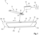
- Figure 1 shows a conveyor belt assembly 10 for transporting single sheets or stacks of packaging material.
- It comprises two conveyor belts 12a, 12b which are arranged in a substantially parallel manner (cf. Figure 2 ).
- first end 14a of each of the support devices 14 is attached to a first conveyor belt 12a and a second end 14b of each of the support devices 14 is attached to a second conveyor belt 12b.
- the support devices 14 extend substantially perpendicular to the conveyor belts 12a, 12b and a conveying direction 15.
- the support devices 14 are rigid and each of them provides a support surface 16 configured to support the single sheets or stacks of packaging material.
- the conveyor belts 12a, 12b are arranged over pulleys 20a, 20b, 20c, 20d (cf. Figures 4 to 7 ).
- At least one of the pulleys 20a to 20d is adapted to drive the corresponding conveyor belt 12a, 12b in the conveying direction 15.
- the pulleys 20a to 20d have diameters of 100 mm to 300 mm.
- the conveyor belt assembly 10 comprises four pulleys 20a to 20d, wherein the respective axis of rotation of the pulleys 20a to 20d are substantially parallel.
- the pulleys 20a to 20d are arranged in a substantially trapezoidal manner, when seen in the direction of the axis of rotation.
- the area of movement of the conveyor belts 12a, 12b and the support devices 14 mounted thereon can be subdivided into different sections.
- a conveying section 22 is adapted for transporting the sheets 18 or stacks of packaging material.
- a return section 24 is adapted to return the conveyor belts 12a, 12b from an end 22b of the conveying section 22 to a beginning 22a of the conveying section 22.
- the return section 24 comprises return section elements 24a, 24b and 24c, wherein return section element 24c is arranged adjacent to the beginning 22a of the conveying section 22 and return section element 24a is neighboring the end 22b of the conveying section 22.
- the conveying section 22 is subdivided into a middle section 26 in which the conveyor belts 12a, 12b are arranged in a substantially flat manner and a transition section 28.
- the conveyor belts 12a, 12b are arranged in a retracted position with respect to a plane 26a defined by the middle section 26.
- the conveyor belt assembly 10 comprises two transition sections 28, wherein one is arranged at the beginning 22a of the conveying section 22 and one is arranged at the end 22b of the conveying section 22.
- the transition section 28 has a curved shape with a radius of approximately 4 m. This means that between the middle section 26 and the area, where the conveyor belts 12a, 12b are in contact with the pulley 20a, the conveyor belts 12a, 12b and the support devices 14 mounted thereon move on a portion of a circle line.
- transition section 28 is plane, but inclined with respect to the middle section 26.
- transition section 28 comprises a curved section with a radius and a plane, but inclined section.
- the transition section 28 has a length l, which is between 50 mm and 600 mm when measured in the conveying direction 15.
- length I of the transition section 28 is larger than the radius (and in these embodiments also than the diameter) of the pulleys 20. Accordingly, the transition section 28 merges into the middle section 26 at a point which is inwardly (meaning: arranged closer to the center of the belt assembly) of the innermost position of the circumference of the respective pulley 20. In other words: if one draws a vertical tangent to the inner side of the pulley (the side which is not covered by belt 12), this tangent runs through the transition section 28.
- the significant length of the transition section 28 ensures that the conveyor belt is smoothly guided from the pulley to the level of the middle section 26, and is smoothly guided from the level of the middle section 26 towards the next pulley.
- a curved section with a radius of about 4 m and a length of about 200 mm is interposed between two straight sections.
- guide rails 30a, 30b, 30c are provided in the conveying section 22.
- the guide rails 30a, 30b, 30c are made of a low friction material and the support devices 14 are in sliding connection with the guide rails 30a, 30b, 30c, when located in the conveying section 22.
- the support devices 14, more precisely the leading edges of the support devices 14, will make contact with the sheet 18 of packaging material, when being tilted in order to arrive in the conveying section 22.
- the contact between the leading edges of the support devices 14 and the sheet 18 of packaging material is due to the radius of the pulley 20d.
- the support devices 14 are rigid and therefore cannot be bent by the radius of the pulley. Consequently, they are arranged in a tangential manner.
- a transition section 28 is provided, wherein the conveyor belt 12a is arranged in a retracted position with respect to the plane 26a defined by the middle section 26.
- Figures 8 and 9 show a detailed view of two embodiments of support devices 14.
- one or more support devices 14 are mounted on the conveyor belts 12a, 12b in order to transport single sheets or stacks of packaging material.
- All support devices 14 of the conveyor assembly 10 can be generally identical, e. g. of the type shown in Figure 8 or Figure 9 .
- different groups of support devices 14 can be mounted on the conveyor belts 12a, 12b, wherein the support devices 14 belonging to the same group are generally identical and the support devices of different groups are generally different.
- five support devices 14 according to Figure 8 can form a first group and five support devices according to Figure 9 can form a second group.
- First groups and second groups can be mounted in an alternating manner on the conveyor belts 12a, 12b.
- each support device 14 comprises a multitude of slats 32 being arranged on a basic component 34.
- the slats 32 are arranged in an upright position and spaced from each other such that respective side contour contact sections 36 of the slats 32 form the substantially flat support surface 16 configured to support the single sheets 18 or stacks of packaging material (see also Figures 10 and 11 ).
- the slats 32 extend obliquely with respect to a direction 34a of general extension of the basic component 34.
- auxiliary lines 38 are oriented perpendicular to the direction 34a of general extension of the basic component 34.
- the slats 32 extend neither perpendicular nor parallel to the direction 34a.
- the conveying direction 15 is generally perpendicular to the direction 34a. Therefore, the slats are also oriented obliquely with respect to the conveying direction 15.
- the angle of rotation of the slats 32 with respect to the direction 34a is exaggerated. In reality this angle is about 0.5° to 15°. In an especially preferred embodiment it is 0.5° to 5°.
- the slats 32 of this embodiment are crescent-shaped, the radius of curvature being substantially equal for all slats 32.
- the slats 32 are crescent-shaped but not oriented obliquely with respect to the conveying direction 15.
- the basic component 34 is a U-shaped profile, wherein the slats 32 generally extend from a first leg 40 to a second leg 42 of the U-shaped profile being opposed to the first leg 40.
- connection area 44 on the first leg 40 is offset from a connection area 46 on the second leg 42, when measured with respect to the direction 34a of general extension of the basic component 34.
- the slats 32 are preloaded with respect to the basic component 34.
- a compressive preload force is applied to the slats 32 by the legs 40, 42 of the basic component 34.
- the slats 32 are preferably made from a steel material, especially from a stainless steel material.
- the tips 50 of the teeth 48 form the substantially flat support surface 16.
- a first embodiment thereof is shown in figure 10 .
- connection tongues 52 which are arranged on opposite ends of the slat 32.
- connection tongues 52 engage corresponding connection slots 54, whereas only some of the slots 54 are equipped with a reference sign.
- the basic component 34 is a U-shaped profile and the connection slots 54 are provided on the legs 40, 42 of the U-shaped profile.
- the slats 32 generally extend from the first leg 40 to the second leg 42 of the U-shaped profile.
- the slots 54 are openings, which means that they are closed on all lateral sides.
- the slats 32 are slightly bent and introduced in the middle section of the U-shaped profile.
- a bending force is released and the slats 32 return elastically to their straight original form.
- the tongues 52 move into the corresponding slots 54.
- each connection tongue 52 is associated with a vertical positioning surface 56, which is arranged on the corresponding slat 32.
- the vertical positioning surface 56 abuts against an end of the corresponding leg 40, 42 of the basic component 34.
- a lower surface 58 of the slats 32 can act as a vertical positioning surface, which then abuts against a ground surface of the basic component 34 in an assembled state.
- vertical positioning surfaces 60 can be provided on the tongues 52. Such vertical positioning surfaces 60 are adapted to cooperate with a ground surface of a corresponding connection slots 54.
- the slats 32 also need to be positioned in a horizontal direction.
- connection tongue 52 is associated with a horizontal positioning surface 62, which is arranged on the corresponding slat 32.
- the horizontal positioning surface 62 comprises a first section 62a which is arranged above the corresponding connection tongue 52 and a second section 62b which is arranged under the corresponding connection tongue 52.
- two types of slots 54 are provided on the basic component 34 wherein the first type of slot is arranged closer to a basic surface of the basic component 34 than a second type of slot.
- the two types of slots 54 are arranged in an alternating manner, when seen in the direction 34a.
- the different types of slots 54 are adapted to cooperate with different types of connection tongues 52.
- connection tongue 52 shown on the right side of the slat 32 is arranged closer to the lower surface 58 than the connection tongue 52 shown on the left side of the slat 32. Consequently, two different types of connection tongues 52 are arranged on one slat 32. In other words, the slat 32 is asymmetrical.
- the slat 32 always cooperates with two slots 54 of different types.
- a first orientation is for example the orientation shown in Figure 10 .
- teeth 48 provided on neighboring slats 32 can be arranged in an offset manner (only represented for the embodiment of Figure 11 ).
- two different types of slats 32 can be used (not shown). Then, a first type of slats 32 is engageable with a first type of slots 54, but not with the second type of slots 54 and a second type of slats 32 is only engageable with a second type of slots 54, but not with the first type of slots 54.
- the first type of slats 32 and the second type of slats 32 can for example differ in the relative position of the teeth 48 on the slats.
- teeth 48 provided on neighboring slats 32 can be arranged in an offset manner (only represented for the embodiment of Figure 11 ).
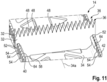
- Figure 11 shows a different embodiment, in which the connection slots 54 are open towards an end of the respective leg 40, 42.
- connection slots 54 In order to mount the slats 32 in the connection slots 54, they are moved in a vertical direction.
- the slats 32 can be fixed to the basic component 34 by gluing.
- a gluing connection 64 is provided on both the first leg 40 and the second leg 42 of the basic component 34.
- each of the slats 32 comprises one connection tongue 52 of the first type and one of the second type.
- the two slats 32 represented in Figure 11 are mounted on the basic component 34 in opposed orientations (see especially half tooth).
- the horizontal positioning surfaces 62 and vertical positioning surfaces 56 of the embodiment according to Figure 11 correspond to the surfaces explained in relation to the embodiment of Figure 10 .
- each support device 14 comprises a multitude of teeth 48. More precisely, on each slat 32 a plurality or group of teeth 48 is formed, wherein the tips 50 of the teeth 48 form the substantially flat support surface 16 configured to support the single sheets or stacks of packaging material.
- All teeth 48 have a substantially triangular shape and extent substantially orthogonal to the support surface 16, wherein the extension of a tooth 48 is defined from a tooth base to the tooth tip 50.
- the teeth 48 are substantially 0,5 mm to 10 mm wide, 0,2 mm to 1,0 mm thick and 1 mm to 15 mm high.
- the teeth are 2 mm to 8 mm wide and 3 mm to 15 mm high.
- the thickness of the teeth 48 corresponds to the thickness of the slat 32 on which the teeth 48 are formed e.g. by cutting, embossing or stamping.
- the tooth tip 50 is rounded by a radius 66 of approximately 0.15 mm.
- Neighboring teeth 48 are separated by a gap 68.
- a recess 70 is arranged on a side of the gap 68, which opposes the tooth tip 50.
- This recess 70 is at least partly rounded, wherein the rounded portion has a radius of about 0.3 mm.
- the recess 70 forms an undercut with respect to the neighboring teeth 48.
- a transition zone 72 between the recess and the rest of the tooth 48 can be rounded, e.g. by a radius of about 0.15 mm.
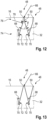
- the tooth 48 shown in Figure 12 comprises a base section 74 and a tip section 76.
- an angle ⁇ between corresponding tooth flanks is smaller than an angle ⁇ between corresponding tooth flanks in the base section 74.
- the angle ⁇ is approximately 10° and the angle ⁇ is approximately 40°.
- the height of the base section 74 is about 2 to 5 times the height of the tip sections 76.
- the flanks of the teeth 48 are generally planar.
- flank sections comprised in the base section 74 and the flank sections comprised in the tip section 76 are substantially planar.
- the transition from the base section 74 to the tip section 76 comprises a radius 78, which is approximately 0.6 mm in the example shown.
- Figure 13 shows a tooth 48 according to a second embodiment.
- the structure of this tooth 48 is simplified with respect to the embodiment of Figure 12 in that it does not show a distinct base section and tip section.
- the teeth 48 on one slat 32 are shaped identically.
- the teeth 48 on one support device 14 are all shaped identically.
Landscapes
- Engineering & Computer Science (AREA)
- Mechanical Engineering (AREA)
- Physics & Mathematics (AREA)
- Optics & Photonics (AREA)
- Plasma & Fusion (AREA)
- Auxiliary Devices For And Details Of Packaging Control (AREA)
- Delivering By Means Of Belts And Rollers (AREA)
- Chain Conveyers (AREA)
- Belt Conveyors (AREA)
- Structure Of Belt Conveyors (AREA)
Description
- The invention relates to a conveyor belt assembly for transporting single sheets or stacks of a packaging material.
- In this context, a stack of a packaging material is to be understood as a plurality of sheets made of the packaging material and being arranged one above the other in a well-defined manner.
- Such conveyor belt assemblies are known in the art, for example in the packaging industry.
- More specifically, such conveyor belt assemblies are used in packaging material cutting or creasing machines, in which the cutting or creasing is performed on-the-fly, i.e. the packaging material is cut or creased while being transported through the machine.
- Usually the packaging material to be cut is held on the conveyor belt assembly by vacuum. In known configurations, a vacuum source, e. g. vacuum pump, is arranged under a conveying section of the conveyor belt assembly, cooperating with vacuum exhausters holding the packaging material tightly to the conveying section.
- For example, document
US 2005/0116396 discloses a conveyor belt assembly with all the features defined in the preamble of claim 1, and in a cutting machine using a laser beam. The conveyor belt is made of a plurality of inserts made of a set of parallel thin metal plates. The conveyor has a flat section surrounded by two pulleys. - For economical reasons cutting or creasing of packaging material has to be done as fast as possible. As a result thereof, the conveying of the packaging material also has to be done at high speed. At the same time, packaging materials can be delicate materials and care has to be taken not to damage the packaging material in any sense, e.g. by scratches, bends or kinks. Generally speaking, the higher the conveying speed, the higher the risk of damaging the packaging material.
- Consequently, it is an object of the present invention to define a conveyor belt assembly of the type mentioned above, which solves the conflict mentioned above. Especially, the conveyor belt assembly of the present invention shall allow high speed conveying of packaging material without risking to damage the packaging material.
- This problem is solved by a conveyor belt assembly as defined in claim 1, comprising at least one conveyor belt being arranged over at least two pulleys, wherein at least one of the pulleys is adapted to drive the conveyor belt in a conveying direction, the conveyor belt assembly comprising a conveying section adapted for transporting the sheets or stacks and a return section adapted to return the conveyor belt from an end of the conveying section to a beginning of the conveying section, wherein the conveying section comprises a middle section, in which the conveyor belt is arranged in a substantially flat manner, and at least one transition section arranged between the middle section and the respective pulley, with the conveyor belt being arranged in the transition section in a retracted position with respect to a plane defined by the middle section. When imagining the plane defined by the middle section as being infinite, the transition section is arranged within a distance of this plane. In the assembled state of the conveyor belt assembly the transition section is always located below this plane. The transition section preferably is arranged in an area where the return section neighbors the conveying section. In usual arrangements, in this area also one of the pulleys is positioned and the conveyor belt covers the pulley by a certain angle. On the conveyor belt rigid support devices are arranged, which are in contact with the packaging material. Each of these support devices comprises a multitude of teeth whose tips form a substantially flat support surface. When these support devices are in the area of one of the pulleys, it is possible that one or more edges thereof protrude from a general conveying surface. These edges present a risk of damaging the packaging material, which increases with higher conveying speed.
- According to the present invention, the retracted position of the transition section produces a gap between the general conveying surface, i.e. the surface where the packaging material is located, and the support devices being mounted on the conveyor belt. Therefore, the risk of damaging the packaging material is effectively eliminated.
- The transition section can be formed by a radius of 3 m to 6 m, especially of about 4 m. Then the conveyor belt moves along this radius, when in the transition section. Thereby a gap separating the support devices of the conveyor belt assembly from the delicate packaging material is created.
- Alternatively, the transition section can be at an angle with respect to the middle section. Also in this configuration, the risk of damaging the packaging material is eliminated.
- The packaging material can be paper, cardboard or a plastic material. Also sheets made of a plurality of materials are possible. Such packaging material sheets for example comprise a layer of paper or cardboard covered with a layer of plastic, which also can be called a coating.
- Preferably, the transition section is arranged at a beginning of the conveying section or at an end of the conveying section when seen in the conveying direction or the conveying section comprises two transition sections, wherein one is arranged at the beginning of the conveying section and one is arranged at the end of the conveying section. Consequently, the transition section is arranged in the area of the pulleys, where the conveyor belt changes its direction of movement. As explained above, also support devices being mounted on the conveyor belt change their direction of movement in this location. In these areas, the risk of damaging the packaging material is high in known conveyor belt assemblies. The transition section according to the invention eliminates or at least reduces the risk of damaging the packaging material. As a consequence thereof, higher conveying speeds are possible.
- The transition section has a length which is more than the radius of the pulleys, thereby merging with the middle section at a point which is in a distance from the axis of rotation of the pulley by more than the radius of the pulley and preferably by more than the diameter of the pulley. The significant length of the transition section ensures the smooth approach of the conveyor belt towards the level of the middle section and the smooth depart from this level, respectively,
- In an embodiment the pulleys have a diameter of 100 mm to 300 mm, preferably approximately 150 mm. It has been found that these diameters combine high potential conveying speed, low risk of damaging the packaging material and low required space. Of course the invention is not limited to these diameters and deviations therefrom are perfectly possible.
- It is preferred that the conveyor belt assembly comprises four pulleys, wherein the respective axis of rotation of the pulleys are substantially parallel and the pulleys are arranged in a substantially trapezoidal manner when seen in the direction of the axis of rotation. In this configuration a vacuum system or other technical devices can be arranged inside the space being defined by the four axis of rotation and the respective lateral surfaces of the conveyor belt. Such a conveyor belt assembly is compact with respect to space requirements. Therefore, it is especially suitable for being integrated in a packaging material cutting or creasing machine.
- The conveying section can comprise a guide rail being adapted to define the form of the conveying section, preferably wherein the guide rail is made from a low friction material. Such a guide rail is used to precisely define the location of the conveyor belt or a support device mounted thereon, even at high conveying speeds. Consequently, the task of positioning the conveying surface including the transition region is performed by the guide rail. The task of moving the conveyor belt is performed by a different device. As a result thereof, the form of the conveying section, especially the transition section is defined in an easy and reliable manner.
- According to the present invention, one or more support devices are mounted on the conveyor belt, wherein each of the support devices provides a support surface configured to support the single sheets or stacks of packaging material. Consequently, a conveying surface is formed by a plurality of adjacent support devices. They can be made from metal material.
- The support devices can be in sliding connection with the guide rail when located in the conveying section. This means that the support devices closely follow the contour defined by the guide rail. This means that the support devices are arranged on a flat plane in the middle section and for example on a radius of 3 m to 6 m in the transition section.
- In a preferred variant two or more guide rails, especially three guide rails, are provided, each being in sliding connection with the support devices. With more than one guide rail the contour to be followed by the conveyor belt and/or the support devices mounted thereon is defined in a more reliable manner. Especially undesired tilting, twisting and turning of the conveyor belt and the support devices connected therewith is prevented. As a consequence the conveyor belt and the support devices precisely follow the contour of the guide rails. Therefore, damaging the packaging material is prevented.
- The conveyor belt assembly can comprise two conveyor belts, which are arranged in a substantially parallel manner. Even though theoretically one conveyor belt is enough, by using two conveyor belts, a more uniform movement of the support devices and thus the packaging material can be achieved. Furthermore, such a conveyor belt assembly can bear higher loads and higher conveying speeds.
- In an embodiment a first end of each of the one or more support devices is attached to a first conveyor belt and a second end of each of the one or more support devices is attached to a second conveyor belt. Preferably, the support devices are screwed to the conveyor belts. This arrangement allows for a uniform conveying movement.
- The support devices can extend substantially perpendicular to the conveying direction.
- According to the present invention, the support devices are substantially rigid. Preferably, the support devices are made from metal or plastics.
- In a variant the transition section is 50 mm to 600 mm long, when measured in the conveying direction. This size of the transition zone guarantees an effective damage prevention concerning the packaging material to be conveyed.
- The invention will now be explained with reference to several embodiments which are shown in the attached drawings. In the drawings,
-
Figure 1 shows a schematic overview of a conveyor belt assembly according to the invention in an exploded view, -
Figure 2 shows a detail of the conveyor belt assembly according toFigure 1 , -
Figure 3 shows the functional principle of a known conveyor belt assembly, -
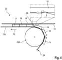
Figure 4 shows an alternative functional principle of another known conveyor belt assembly, -
Figure 5 shows the geometry of a transition section of a conveyor belt assembly according to the invention, -
Figure 6 shows an alternative geometry of a transition section of a conveyor belt assembly according to the invention, -
Figure 7 shows a detailed overview of a conveyor belt assembly according to the invention, -
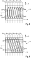
Figure 8 shows an embodiment of a support device according to the invention, -
Figure 9 shows an alternative embodiment of a support device according to the invention, -
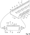
Figure 10 shows an exploded view of a support device according to the invention, wherein only one exemplary slat is shown, -
Figure 11 shows an alternative embodiment of a support device according to the invention, wherein two exemplary slats are shown, -
Figure 12 shows a detailed view of a tooth of a support device according to the invention, and -
Figure 13 shows a detailed view of an alternative tooth of a support device according to the invention. -
Figure 1 shows aconveyor belt assembly 10 for transporting single sheets or stacks of packaging material. - It comprises two
conveyor belts Figure 2 ). - On the
conveyor belts support devices 14 are mounted. - More precisely, a
first end 14a of each of thesupport devices 14 is attached to afirst conveyor belt 12a and asecond end 14b of each of thesupport devices 14 is attached to asecond conveyor belt 12b. - The
support devices 14 extend substantially perpendicular to theconveyor belts direction 15. - The
support devices 14 are rigid and each of them provides asupport surface 16 configured to support the single sheets or stacks of packaging material. - In the figures a
single sheet 18 of packaging material can be seen. It is also representative of stacks of packaging material. - In order to convey the sheets or stacks of packaging material, the
conveyor belts pulleys Figures 4 to 7 ). - For each conveyor belt at least one of the
pulleys 20a to 20d is adapted to drive the correspondingconveyor belt direction 15. - The
pulleys 20a to 20d have diameters of 100 mm to 300 mm. - In the example shown, the
conveyor belt assembly 10 comprises fourpulleys 20a to 20d, wherein the respective axis of rotation of thepulleys 20a to 20d are substantially parallel. - As can especially be seen from
Figures 5 and6 , thepulleys 20a to 20d are arranged in a substantially trapezoidal manner, when seen in the direction of the axis of rotation. - The area of movement of the
conveyor belts support devices 14 mounted thereon can be subdivided into different sections. - A conveying
section 22 is adapted for transporting thesheets 18 or stacks of packaging material. - A
return section 24 is adapted to return theconveyor belts end 22b of the conveyingsection 22 to abeginning 22a of the conveyingsection 22. - In the example the
return section 24 comprisesreturn section elements return section element 24c is arranged adjacent to thebeginning 22a of the conveyingsection 22 andreturn section element 24a is neighboring theend 22b of the conveyingsection 22. - The conveying
section 22 is subdivided into amiddle section 26 in which theconveyor belts transition section 28. - In the
transition section 28 theconveyor belts plane 26a defined by themiddle section 26. - As shown, the
conveyor belt assembly 10 comprises twotransition sections 28, wherein one is arranged at thebeginning 22a of the conveyingsection 22 and one is arranged at theend 22b of the conveyingsection 22. - It is noted that in
Figure 1 only an enveloping geometry is shown, in which theconveyor belts support devices 14 are movable. - In the embodiment according to
Figure 5 thetransition section 28 has a curved shape with a radius of approximately 4 m. This means that between themiddle section 26 and the area, where theconveyor belts pulley 20a, theconveyor belts support devices 14 mounted thereon move on a portion of a circle line. - In the alternative embodiment shown in
Figure 6 thetransition section 28 is plane, but inclined with respect to themiddle section 26. - Also a combination of the embodiments shown in
Figures 5 and6 is possible, i. e. thetransition section 28 comprises a curved section with a radius and a plane, but inclined section. - The
transition section 28 has a length l, which is between 50 mm and 600 mm when measured in the conveyingdirection 15. - As can be seen in
Figure 5 and6 , length I of thetransition section 28 is larger than the radius (and in these embodiments also than the diameter) of the pulleys 20. Accordingly, thetransition section 28 merges into themiddle section 26 at a point which is inwardly (meaning: arranged closer to the center of the belt assembly) of the innermost position of the circumference of the respective pulley 20. In other words: if one draws a vertical tangent to the inner side of the pulley (the side which is not covered by belt 12), this tangent runs through thetransition section 28. - The significant length of the
transition section 28 ensures that the conveyor belt is smoothly guided from the pulley to the level of themiddle section 26, and is smoothly guided from the level of themiddle section 26 towards the next pulley. - In a preferred embodiment, a curved section with a radius of about 4 m and a length of about 200 mm is interposed between two straight sections.
- In order to move the
conveyor belts support devices 14 mounted thereon on the geometry described above,guide rails section 22. - The
guide rails support devices 14 are in sliding connection with theguide rails section 22. - The effect produced by the
conveyor belt assembly 10 can best be understood fromFigures 3 ,4 and7 . - All three figures show
conveyor belt 12a and a selection ofsupport devices 14 mounted thereon, which are about to move from thereturn section 24 to the conveyingsection 22. - In the prior art solution shown in
Figure 3 , thesupport devices 14, more precisely the leading edges of thesupport devices 14, will make contact with thesheet 18 of packaging material, when being tilted in order to arrive in the conveyingsection 22. - The contact between the leading edges of the
support devices 14 and thesheet 18 of packaging material is due to the radius of thepulley 20d. Thesupport devices 14 are rigid and therefore cannot be bent by the radius of the pulley. Consequently, they are arranged in a tangential manner. - In the prior art solution shown in
Figure 4 thesupport devices 14 are attached to theconveyor belt 12a in a different manner. This leads to the fact that in the area where thesupport devices 14 are being tilted in order to arrive in the conveyingsection 22 neighboring trailing edges and leading edges move at different speeds. At the same time, both edges are in contact with thesheet 18 of packaging material. - In the cases shown in
Figures 3 and4 thesheet 18 of packaging material risks to be damaged. - As can be seen from
Figure 7 , atransition section 28 is provided, wherein theconveyor belt 12a is arranged in a retracted position with respect to theplane 26a defined by themiddle section 26. - Therefore, in the area where the
support devices 14 are tilted into the conveyingsection 22 and leave contact with thepulley 20d at the same time, a gap between thesheet 18 of packaging material and thesupport devices 14, especially their leading edge is provided. - As a consequence thereof, damage of the
sheet 18 of packaging material can effectively be prevented. -
Figures 8 and 9 show a detailed view of two embodiments ofsupport devices 14. - As already has been explained, one or
more support devices 14 are mounted on theconveyor belts - All
support devices 14 of theconveyor assembly 10 can be generally identical, e. g. of the type shown inFigure 8 or Figure 9 . - Alternatively, different groups of
support devices 14 can be mounted on theconveyor belts support devices 14 belonging to the same group are generally identical and the support devices of different groups are generally different. - For example, five
support devices 14 according toFigure 8 can form a first group and five support devices according toFigure 9 can form a second group. First groups and second groups can be mounted in an alternating manner on theconveyor belts - Generally speaking, each
support device 14 comprises a multitude ofslats 32 being arranged on abasic component 34. - On this
basic component 34 theslats 32 are arranged in an upright position and spaced from each other such that respective sidecontour contact sections 36 of theslats 32 form the substantiallyflat support surface 16 configured to support thesingle sheets 18 or stacks of packaging material (see alsoFigures 10 and11 ). - As can be seen from
Figures 8 and 9 allslats 32 are arranged in a substantially parallel manner on thebasic component 34. In this context parallel means that a distance between two neighboringslats 32 is constant. - At the same time the
slats 32 extend obliquely with respect to adirection 34a of general extension of thebasic component 34. - In
Figures 8 and 9 auxiliary lines 38 are oriented perpendicular to thedirection 34a of general extension of thebasic component 34. - Consequently, the
slats 32 extend neither perpendicular nor parallel to thedirection 34a. - As has already been explained, the conveying
direction 15 is generally perpendicular to thedirection 34a. Therefore, the slats are also oriented obliquely with respect to the conveyingdirection 15. - In the embodiment of
Figure 9 the slats are substantially straight. - The angle of rotation of the
slats 32 with respect to thedirection 34a is exaggerated. In reality this angle is about 0.5° to 15°. In an especially preferred embodiment it is 0.5° to 5°. - For the embodiment of
Figure 8 the same angle of rotation applies, but the representation is not exaggerated in this case. - The
slats 32 of this embodiment are crescent-shaped, the radius of curvature being substantially equal for allslats 32. - In a further alternative the
slats 32 are crescent-shaped but not oriented obliquely with respect to the conveyingdirection 15. - As can best be seen from
figure 10 thebasic component 34 is a U-shaped profile, wherein theslats 32 generally extend from afirst leg 40 to asecond leg 42 of the U-shaped profile being opposed to thefirst leg 40. - In order to achieve the oblique positions of the
slats 32, aconnection area 44 on thefirst leg 40 is offset from aconnection area 46 on thesecond leg 42, when measured with respect to thedirection 34a of general extension of thebasic component 34. - Furthermore, the
slats 32 are preloaded with respect to thebasic component 34. In this context a compressive preload force is applied to theslats 32 by thelegs basic component 34. - The
slats 32 are preferably made from a steel material, especially from a stainless steel material. - The
tips 50 of theteeth 48 form the substantiallyflat support surface 16. - In the following the assembly of the
slats 32 to the respectivebasic component 34 will be explained in detail. - A first embodiment thereof is shown in
figure 10 . - Each
slat 32 is mounted to thebasic component 34 by twoconnection tongues 52, which are arranged on opposite ends of theslat 32. In the assembled state, theconnection tongues 52 engage correspondingconnection slots 54, whereas only some of theslots 54 are equipped with a reference sign. - As already explained above, the
basic component 34 is a U-shaped profile and theconnection slots 54 are provided on thelegs - Consequently, the
slats 32 generally extend from thefirst leg 40 to thesecond leg 42 of the U-shaped profile. - In the embodiment according to
Figure 10 theslots 54 are openings, which means that they are closed on all lateral sides. - During assembly the
slats 32 are slightly bent and introduced in the middle section of the U-shaped profile. When thetongues 52 are in the proximity of acorresponding slot 54, a bending force is released and theslats 32 return elastically to their straight original form. At the same time thetongues 52 move into the correspondingslots 54. - In order to vertically position the
slats 32 with respect to thebasic component 34 eachconnection tongue 52 is associated with a vertical positioning surface 56, which is arranged on the correspondingslat 32. - In the example shown the vertical positioning surface 56 abuts against an end of the
corresponding leg basic component 34. - Alternatively, a
lower surface 58 of theslats 32 can act as a vertical positioning surface, which then abuts against a ground surface of thebasic component 34 in an assembled state. - In a further alternative, vertical positioning surfaces 60 can be provided on the
tongues 52. Such vertical positioning surfaces 60 are adapted to cooperate with a ground surface of acorresponding connection slots 54. - The
slats 32 also need to be positioned in a horizontal direction. - To this end each
connection tongue 52 is associated with a horizontal positioning surface 62, which is arranged on the correspondingslat 32. - In the example shown in
Figure 10 the horizontal positioning surface 62 comprises a first section 62a which is arranged above thecorresponding connection tongue 52 and a second section 62b which is arranged under thecorresponding connection tongue 52. - As can best be seen from
figure 10 , two types ofslots 54 are provided on thebasic component 34 wherein the first type of slot is arranged closer to a basic surface of thebasic component 34 than a second type of slot. - The two types of
slots 54 are arranged in an alternating manner, when seen in thedirection 34a. - The different types of
slots 54 are adapted to cooperate with different types ofconnection tongues 52. - In the example shown in
Figure 10 theconnection tongue 52 shown on the right side of theslat 32 is arranged closer to thelower surface 58 than theconnection tongue 52 shown on the left side of theslat 32. Consequently, two different types ofconnection tongues 52 are arranged on oneslat 32. In other words, theslat 32 is asymmetrical. - Consequently, the
slat 32 always cooperates with twoslots 54 of different types. - As the types of
slots 54 are arranged in an alternating manner, theslats 32 are mounted in alternating orientations. Thereby, a first orientation is for example the orientation shown inFigure 10 . - To change the orientation of the
slat 32 it is turned by 180° with respect to a vertical axis. - Thereby, the
teeth 48 provided on neighboringslats 32 can be arranged in an offset manner (only represented for the embodiment ofFigure 11 ). - Alternatively, two different types of
slats 32 can be used (not shown). Then, a first type ofslats 32 is engageable with a first type ofslots 54, but not with the second type ofslots 54 and a second type ofslats 32 is only engageable with a second type ofslots 54, but not with the first type ofslots 54. - The first type of
slats 32 and the second type ofslats 32 can for example differ in the relative position of theteeth 48 on the slats. - Also by this means the
teeth 48 provided on neighboringslats 32 can be arranged in an offset manner (only represented for the embodiment ofFigure 11 ). -
Figure 11 shows a different embodiment, in which theconnection slots 54 are open towards an end of therespective leg - In order to mount the
slats 32 in theconnection slots 54, they are moved in a vertical direction. - Additionally, the
slats 32 can be fixed to thebasic component 34 by gluing. In the example shown, agluing connection 64 is provided on both thefirst leg 40 and thesecond leg 42 of thebasic component 34. - As already explained in connection with the embodiment of
Figure 10 also the embodiment ofFigure 11 comprises two types ofslots 54 being able to cooperate with two different types ofconnection tongues 52 respectively. As in the embodiment ofFigure 10 each of theslats 32 comprises oneconnection tongue 52 of the first type and one of the second type. - The two
slats 32 represented inFigure 11 are mounted on thebasic component 34 in opposed orientations (see especially half tooth). - The horizontal positioning surfaces 62 and vertical positioning surfaces 56 of the embodiment according to
Figure 11 correspond to the surfaces explained in relation to the embodiment ofFigure 10 . - As can be seen from the above and according to the present invention, each
support device 14 comprises a multitude ofteeth 48. More precisely, on each slat 32 a plurality or group ofteeth 48 is formed, wherein thetips 50 of theteeth 48 form the substantiallyflat support surface 16 configured to support the single sheets or stacks of packaging material. - In
Figure 12 , a first embodiment of thetooth 48 is shown in detail. - All
teeth 48 have a substantially triangular shape and extent substantially orthogonal to thesupport surface 16, wherein the extension of atooth 48 is defined from a tooth base to thetooth tip 50. - The
teeth 48 are substantially 0,5 mm to 10 mm wide, 0,2 mm to 1,0 mm thick and 1 mm to 15 mm high. Preferably, the teeth are 2 mm to 8 mm wide and 3 mm to 15 mm high. - The thickness of the
teeth 48 corresponds to the thickness of theslat 32 on which theteeth 48 are formed e.g. by cutting, embossing or stamping. - The
tooth tip 50 is rounded by aradius 66 of approximately 0.15 mm. - Neighboring
teeth 48 are separated by agap 68. In the examples shown, on a side of thegap 68, which opposes thetooth tip 50, arecess 70 is arranged. - This
recess 70 is at least partly rounded, wherein the rounded portion has a radius of about 0.3 mm. - Furthermore, the
recess 70 forms an undercut with respect to the neighboringteeth 48. - Also a
transition zone 72 between the recess and the rest of thetooth 48 can be rounded, e.g. by a radius of about 0.15 mm. - The
tooth 48 shown inFigure 12 comprises abase section 74 and atip section 76. In thetip section 76 an angle α between corresponding tooth flanks is smaller than an angle β between corresponding tooth flanks in thebase section 74. - In the example shown, the angle α is approximately 10° and the angle β is approximately 40°.
- In terms of proportions the height of the
base section 74 is about 2 to 5 times the height of thetip sections 76. - The flanks of the
teeth 48 are generally planar. - In the embodiment of
Figure 12 , the flank sections comprised in thebase section 74 and the flank sections comprised in thetip section 76 are substantially planar. - The transition from the
base section 74 to thetip section 76 comprises aradius 78, which is approximately 0.6 mm in the example shown. -
Figure 13 shows atooth 48 according to a second embodiment. The structure of thistooth 48 is simplified with respect to the embodiment ofFigure 12 in that it does not show a distinct base section and tip section. - Preferably, the
teeth 48 on oneslat 32 are shaped identically. - Furthermore, it is preferred that the
teeth 48 on onesupport device 14 are all shaped identically.
Claims (11)
- Conveyor belt assembly (10) for transporting single sheets (18) or stacks of a packaging material, comprising at least one conveyor belt (12a, 12b) being arranged over at least two pulleys (20a - 20d), wherein at least one of the pulleys (20a - 20d) is adapted to drive the conveyor belt (12a, 12b) in a conveying direction (15), wherein one or more rigid support devices (14) are mounted on the conveyor belt (12a, 12b), the conveyor belt assembly (10) comprising a conveying section (22) adapted for transporting the sheets (18) or stacks and a return section (24) adapted to return the conveyor belt (12a, 12b) from an end (22b) of the conveying section (22) to a beginning (22a) of the conveying section (22), wherein the conveying section (22) comprises a middle section (26), in which the conveyor belt (12a, 12b) is arranged in a substantially flat manner,characterised in that the conveying section (22) comprises at least one transition section (28) arranged between the middle section (26) and the respective pulley (20a - 20d), with the conveyor belt (12a, 12b) being arranged in the transition section (28) in a retracted position with respect to a plane (26a) defined by the middle section (26) to produce a gap between said transition section (28) and said plane (26a),and in that each of the support devices (14) comprises a multitude of teeth (48) whose tips (50) form a substantially flat support surface (16), configured to support the single sheets (18) or stacks of packaging material.
- Conveyor belt assembly (10) according to claim 1, characterized in that the transition section (28) is arranged at a beginning (22a) of the conveying section (22) or at an end (22b) of the conveying section (22) when seen in the conveying direction (15) or wherein the conveying section (22) comprises two transition sections (28), wherein one is arranged at the beginning (22a) of the conveying section (22) and one is arranged at the end (22b) of the conveying section (22).
- Conveyor belt assembly (10) according to any of the preceding claims, characterized in that it comprises four pulleys (20a - 20d), wherein the respective axis of rotation of the pulleys (20a - 20d) are substantially parallel and the pulleys (20a - 20d) are arranged in a substantially trapezoidal manner, when seen in the direction of the axis of rotation.
- Conveyor belt assembly (10) according to any of the preceding claims, characterized in that the conveying section (22) comprises a guide rail (30a - 30c) being adapted to define the form of the conveying section (22), preferably wherein the guide rail (30a - 30c) is made from a low friction material.
- Conveyor belt assembly (10) according to claim 4, characterized in that the support devices (14) are in sliding connection with the guide rail (30a - 30c), when located in the conveying section (22).
- Conveyor belt assembly (10) according to claim 5, characterized in that two or more guide rails (30a - 30c), especially three guide rails (30a - 30c), are provided, each being in sliding connection with the support devices (14).
- Conveyor belt assembly (10) according to any of the preceding claims, characterized in that the conveyor belt assembly (10) comprises two conveyor belts (12a, 12b), which are arranged in a substantially parallel manner.
- Conveyor belt assembly (10) according to claim 7 and one of claims 5 or 6, characterized in that a first end (14a) of each of the one or more support devices (14) is attached to a first conveyor belt (12a) and a second end (14b) of each of the one or more support devices (14) is attached to a second conveyor belt (12b).
- Conveyor belt assembly (10) according to claim 1, characterized in that the support devices (14) extend substantially perpendicular to the conveying direction (15).
- Conveyor belt assembly (10) of any of the preceding claims wherein the transition section (28) has a length which is more than the radius of the pulleys (20).
- Conveyor belt assembly (10) according to any of the preceding claims, characterized in that the transition section (28) is 50 mm to 600 mm long, when measured in the conveying direction (15).
Applications Claiming Priority (2)
| Application Number | Priority Date | Filing Date | Title |
|---|---|---|---|
| EP18020022 | 2018-01-15 | ||
| PCT/EP2019/025008 WO2019137829A1 (en) | 2018-01-15 | 2019-01-09 | Conveyor belt assembly |
Publications (2)
| Publication Number | Publication Date |
|---|---|
| EP3740342A1 EP3740342A1 (en) | 2020-11-25 |
| EP3740342B1 true EP3740342B1 (en) | 2023-04-12 |
Family
ID=60990620
Family Applications (1)
| Application Number | Title | Priority Date | Filing Date |
|---|---|---|---|
| EP19700443.5A Active EP3740342B1 (en) | 2018-01-15 | 2019-01-09 | Conveyor belt assembly |
Country Status (6)
| Country | Link |
|---|---|
| US (1) | US11332314B2 (en) |
| EP (1) | EP3740342B1 (en) |
| CN (1) | CN111615493B (en) |
| ES (1) | ES2943467T3 (en) |
| TW (1) | TWI802632B (en) |
| WO (1) | WO2019137829A1 (en) |
Families Citing this family (4)
| Publication number | Priority date | Publication date | Assignee | Title |
|---|---|---|---|---|
| ES2909525T3 (en) * | 2018-01-15 | 2022-05-06 | Bobst Mex Sa | Support device with slats mounted on a basic component for storing or transporting single sheets or stacks of a packaging material |
| WO2020081241A1 (en) * | 2018-10-17 | 2020-04-23 | WCCO Belting, Inc. | Universal belted chain |
| AU2021206819A1 (en) * | 2021-07-20 | 2023-02-09 | Apap and Grima Pty Ltd | Improved Conveyor System |
| CN113734863B (en) * | 2021-09-14 | 2023-04-11 | 湖南华菱线缆股份有限公司 | Rubber belt feeding and conveying system for cable sheath extrusion feeding |
Citations (1)
| Publication number | Priority date | Publication date | Assignee | Title |
|---|---|---|---|---|
| US20060096243A1 (en) * | 2004-11-05 | 2006-05-11 | Weaver J M | Case packer with a segmented drivable riding strip and segmented drivable riding strip therefore |
Family Cites Families (26)
| Publication number | Priority date | Publication date | Assignee | Title |
|---|---|---|---|---|
| US1030479A (en) * | 1911-06-21 | 1912-06-25 | Nicholas J Ofstad | Fruit-grader. |
| US1779381A (en) * | 1927-04-27 | 1930-10-21 | United Eng Foundry Co | Coil conveyer |
| US2851146A (en) * | 1955-11-10 | 1958-09-09 | Reynolds Tobacco Co R | Apparatus for distributing cartons or the like |
| US3147848A (en) | 1963-03-25 | 1964-09-08 | Grace W R & Co | Conveyor and transfer apparatus |
| JPS5111583U (en) * | 1974-07-15 | 1976-01-28 | ||
| DE3542198A1 (en) * | 1985-11-29 | 1987-06-04 | Elastogran Masch Bau | Double plate belt for the continuous production of laminated foam blocks |
| US4759433A (en) * | 1986-09-15 | 1988-07-26 | Doboy Packaging Machinery, Inc. | Continuous motion, in-line product stacking apparatus |
| DE59207053D1 (en) * | 1992-02-05 | 1996-10-10 | Ferag Ag | Chain deflection |
| FR2849794B1 (en) | 2003-01-09 | 2006-05-05 | S M T C | LATTE FOR LASER DECOUPLE MACHINE TABLE |
| DE10359014A1 (en) | 2003-12-15 | 2005-08-04 | Hans-Joachim Lortz | Object transport decelerating rail, has receptacles arranged on belt conveyor at definite intervals and attached to conveyor through magnetic force in detachable manner, and drive units displacing and leading receptacles to conveyor |
| WO2009024163A1 (en) | 2007-08-20 | 2009-02-26 | Trumpf Werkzeugmaschinen Gmbh + Co.Kg | Workpiece support for receiving an especially plate-shaped workpiece, in a machining installation |
| CN101402276A (en) * | 2007-10-29 | 2009-04-08 | 陆新田 | Transmission structure for conveyer belt for screen decorating machine |
| EP2133290B1 (en) * | 2008-06-13 | 2011-11-16 | Advanced Nuclear Fuels GmbH | Conveying and isolating device |
| DE102010030417B3 (en) | 2010-06-23 | 2011-12-15 | Trumpf Sachsen Gmbh | Display device for displaying setting positions of workpiece support elements at support structure of support of laser processing machine for machining sheet metal parts, has display parts controlled depending upon positions |
| DE102011106469A1 (en) | 2011-06-14 | 2012-12-20 | Mtu Friedrichshafen Gmbh | Strip-shaped workpiece support element useful for forming a workpiece support for thermally cutting material processing device, comprises two longitudinal sides extending two-dimensionally for forming a respective workpiece support area |
| CN102390679B (en) | 2011-07-13 | 2013-05-01 | 江阴纳尔捷机器人有限公司 | One-rail two-speed material conveying system |
| CN203245128U (en) | 2013-03-11 | 2013-10-23 | 章志涛 | Fruit and vegetable multilevel sorting machine |
| WO2015027346A1 (en) * | 2013-08-27 | 2015-03-05 | Andritz Soutec Ag | Method for continuously conveying and butt-welding sheet metal parts, and use of said method |
| CN103754567B (en) | 2013-12-31 | 2016-05-04 | 广州奥迪通用照明有限公司 | A kind of conveyer line with guide rail |
| US9227432B2 (en) * | 2014-03-03 | 2016-01-05 | Kyocera Document Solutions Inc. | Conveyor device and inkjet recording device including conveyor device |
| JP6319656B2 (en) * | 2014-05-02 | 2018-05-09 | 株式会社リコー | Belt device and image forming apparatus having the same |
| KR20150137354A (en) | 2014-05-29 | 2015-12-09 | 주식회사 에이치케이 | Laser cutting apparatus |
| DE102014109157A1 (en) * | 2014-06-30 | 2015-12-31 | Sig Technology Ag | Device for transporting objects |
| CN104176429B (en) * | 2014-09-11 | 2017-02-15 | 衡阳师范学院 | Conveying belt type feeding device |
| CN205414712U (en) | 2016-03-14 | 2016-08-03 | 南京新华人防设备有限公司 | Steel sheet laser cutting device |
| EP3248451B1 (en) * | 2016-05-25 | 2019-04-03 | AGCO Corporation | Chain and slat conveyor and method of assembly |
-
2019
- 2019-01-09 US US16/962,156 patent/US11332314B2/en active Active
- 2019-01-09 ES ES19700443T patent/ES2943467T3/en active Active
- 2019-01-09 CN CN201980008522.7A patent/CN111615493B/en active Active
- 2019-01-09 EP EP19700443.5A patent/EP3740342B1/en active Active
- 2019-01-09 WO PCT/EP2019/025008 patent/WO2019137829A1/en not_active Ceased
- 2019-01-14 TW TW108101338A patent/TWI802632B/en active
Patent Citations (1)
| Publication number | Priority date | Publication date | Assignee | Title |
|---|---|---|---|---|
| US20060096243A1 (en) * | 2004-11-05 | 2006-05-11 | Weaver J M | Case packer with a segmented drivable riding strip and segmented drivable riding strip therefore |
Also Published As
| Publication number | Publication date |
|---|---|
| EP3740342A1 (en) | 2020-11-25 |
| TW201932387A (en) | 2019-08-16 |
| CN111615493B (en) | 2023-02-03 |
| ES2943467T3 (en) | 2023-06-13 |
| WO2019137829A1 (en) | 2019-07-18 |
| CN111615493A (en) | 2020-09-01 |
| US11332314B2 (en) | 2022-05-17 |
| TWI802632B (en) | 2023-05-21 |
| US20200407167A1 (en) | 2020-12-31 |
Similar Documents
| Publication | Publication Date | Title |
|---|---|---|
| US11332314B2 (en) | Conveyor belt assembly | |
| US7963389B2 (en) | Conveyor | |
| US20240367911A1 (en) | Roller conveyor gap blocker | |
| EP3740341B1 (en) | Support device with slats mounted on a basic components, for storing or transporting single sheets or stacks of a packaging material | |
| US10556745B2 (en) | Drive system for conveyors | |
| US20120103762A1 (en) | Conveyor with parallel conveyor members defining a helical path | |
| JP6140309B2 (en) | Device for transporting planar objects | |
| EP2648998B1 (en) | A transfer conveyor and a conveying system | |
| US11261048B2 (en) | Layboy having at least one diverted belt section | |
| AU2018294386B2 (en) | Conveying device having two conveying carts and cover for covering a space between the two conveying carts | |
| US20030047423A1 (en) | Skewed-roller belt drive for belt-driven roller conveyor | |
| JP2023535525A (en) | Direct drive drum for modular conveyor belts | |
| US20240375903A1 (en) | Conveyor having opposed upper and lower decks and laterally shiftable lower deck | |
| JPH08225177A (en) | Paper transport device | |
| US12208983B2 (en) | Stacking device and transport block for a stacking device | |
| JP5976587B2 (en) | Container assembly device |
Legal Events
| Date | Code | Title | Description |
|---|---|---|---|
| STAA | Information on the status of an ep patent application or granted ep patent |
Free format text: STATUS: UNKNOWN |
|
| STAA | Information on the status of an ep patent application or granted ep patent |
Free format text: STATUS: THE INTERNATIONAL PUBLICATION HAS BEEN MADE |
|
| PUAI | Public reference made under article 153(3) epc to a published international application that has entered the european phase |
Free format text: ORIGINAL CODE: 0009012 |
|
| STAA | Information on the status of an ep patent application or granted ep patent |
Free format text: STATUS: REQUEST FOR EXAMINATION WAS MADE |
|
| 17P | Request for examination filed |
Effective date: 20200713 |
|
| AK | Designated contracting states |
Kind code of ref document: A1 Designated state(s): AL AT BE BG CH CY CZ DE DK EE ES FI FR GB GR HR HU IE IS IT LI LT LU LV MC MK MT NL NO PL PT RO RS SE SI SK SM TR |
|
| AX | Request for extension of the european patent |
Extension state: BA ME |
|
| DAV | Request for validation of the european patent (deleted) | ||
| DAX | Request for extension of the european patent (deleted) | ||
| STAA | Information on the status of an ep patent application or granted ep patent |
Free format text: STATUS: EXAMINATION IS IN PROGRESS |
|
| 17Q | First examination report despatched |
Effective date: 20210901 |
|
| GRAP | Despatch of communication of intention to grant a patent |
Free format text: ORIGINAL CODE: EPIDOSNIGR1 |
|
| STAA | Information on the status of an ep patent application or granted ep patent |
Free format text: STATUS: GRANT OF PATENT IS INTENDED |
|
| INTG | Intention to grant announced |
Effective date: 20230125 |
|
| GRAS | Grant fee paid |
Free format text: ORIGINAL CODE: EPIDOSNIGR3 |
|
| GRAA | (expected) grant |
Free format text: ORIGINAL CODE: 0009210 |
|
| STAA | Information on the status of an ep patent application or granted ep patent |
Free format text: STATUS: THE PATENT HAS BEEN GRANTED |
|
| AK | Designated contracting states |
Kind code of ref document: B1 Designated state(s): AL AT BE BG CH CY CZ DE DK EE ES FI FR GB GR HR HU IE IS IT LI LT LU LV MC MK MT NL NO PL PT RO RS SE SI SK SM TR |
|
| REG | Reference to a national code |
Ref country code: GB Ref legal event code: FG4D |
|
| REG | Reference to a national code |
Ref country code: CH Ref legal event code: EP |
|
| REG | Reference to a national code |
Ref country code: DE Ref legal event code: R096 Ref document number: 602019027438 Country of ref document: DE |
|
| REG | Reference to a national code |
Ref country code: IE Ref legal event code: FG4D |
|
| REG | Reference to a national code |
Ref country code: AT Ref legal event code: REF Ref document number: 1559502 Country of ref document: AT Kind code of ref document: T Effective date: 20230515 |
|
| REG | Reference to a national code |
Ref country code: ES Ref legal event code: FG2A Ref document number: 2943467 Country of ref document: ES Kind code of ref document: T3 Effective date: 20230613 |
|
| P01 | Opt-out of the competence of the unified patent court (upc) registered |
Effective date: 20230519 |
|
| REG | Reference to a national code |
Ref country code: LT Ref legal event code: MG9D |
|
| REG | Reference to a national code |
Ref country code: NL Ref legal event code: MP Effective date: 20230412 |
|
| REG | Reference to a national code |
Ref country code: AT Ref legal event code: MK05 Ref document number: 1559502 Country of ref document: AT Kind code of ref document: T Effective date: 20230412 |
|
| PG25 | Lapsed in a contracting state [announced via postgrant information from national office to epo] |
Ref country code: NL Free format text: LAPSE BECAUSE OF FAILURE TO SUBMIT A TRANSLATION OF THE DESCRIPTION OR TO PAY THE FEE WITHIN THE PRESCRIBED TIME-LIMIT Effective date: 20230412 |
|
| PG25 | Lapsed in a contracting state [announced via postgrant information from national office to epo] |
Ref country code: SE Free format text: LAPSE BECAUSE OF FAILURE TO SUBMIT A TRANSLATION OF THE DESCRIPTION OR TO PAY THE FEE WITHIN THE PRESCRIBED TIME-LIMIT Effective date: 20230412 Ref country code: PT Free format text: LAPSE BECAUSE OF FAILURE TO SUBMIT A TRANSLATION OF THE DESCRIPTION OR TO PAY THE FEE WITHIN THE PRESCRIBED TIME-LIMIT Effective date: 20230814 Ref country code: NO Free format text: LAPSE BECAUSE OF FAILURE TO SUBMIT A TRANSLATION OF THE DESCRIPTION OR TO PAY THE FEE WITHIN THE PRESCRIBED TIME-LIMIT Effective date: 20230712 Ref country code: AT Free format text: LAPSE BECAUSE OF FAILURE TO SUBMIT A TRANSLATION OF THE DESCRIPTION OR TO PAY THE FEE WITHIN THE PRESCRIBED TIME-LIMIT Effective date: 20230412 |
|
| PG25 | Lapsed in a contracting state [announced via postgrant information from national office to epo] |
Ref country code: RS Free format text: LAPSE BECAUSE OF FAILURE TO SUBMIT A TRANSLATION OF THE DESCRIPTION OR TO PAY THE FEE WITHIN THE PRESCRIBED TIME-LIMIT Effective date: 20230412 Ref country code: PL Free format text: LAPSE BECAUSE OF FAILURE TO SUBMIT A TRANSLATION OF THE DESCRIPTION OR TO PAY THE FEE WITHIN THE PRESCRIBED TIME-LIMIT Effective date: 20230412 Ref country code: LV Free format text: LAPSE BECAUSE OF FAILURE TO SUBMIT A TRANSLATION OF THE DESCRIPTION OR TO PAY THE FEE WITHIN THE PRESCRIBED TIME-LIMIT Effective date: 20230412 Ref country code: LT Free format text: LAPSE BECAUSE OF FAILURE TO SUBMIT A TRANSLATION OF THE DESCRIPTION OR TO PAY THE FEE WITHIN THE PRESCRIBED TIME-LIMIT Effective date: 20230412 Ref country code: IS Free format text: LAPSE BECAUSE OF FAILURE TO SUBMIT A TRANSLATION OF THE DESCRIPTION OR TO PAY THE FEE WITHIN THE PRESCRIBED TIME-LIMIT Effective date: 20230812 Ref country code: HR Free format text: LAPSE BECAUSE OF FAILURE TO SUBMIT A TRANSLATION OF THE DESCRIPTION OR TO PAY THE FEE WITHIN THE PRESCRIBED TIME-LIMIT Effective date: 20230412 Ref country code: GR Free format text: LAPSE BECAUSE OF FAILURE TO SUBMIT A TRANSLATION OF THE DESCRIPTION OR TO PAY THE FEE WITHIN THE PRESCRIBED TIME-LIMIT Effective date: 20230713 Ref country code: AL Free format text: LAPSE BECAUSE OF FAILURE TO SUBMIT A TRANSLATION OF THE DESCRIPTION OR TO PAY THE FEE WITHIN THE PRESCRIBED TIME-LIMIT Effective date: 20230412 |
|
| PG25 | Lapsed in a contracting state [announced via postgrant information from national office to epo] |
Ref country code: FI Free format text: LAPSE BECAUSE OF FAILURE TO SUBMIT A TRANSLATION OF THE DESCRIPTION OR TO PAY THE FEE WITHIN THE PRESCRIBED TIME-LIMIT Effective date: 20230412 |
|
| REG | Reference to a national code |
Ref country code: DE Ref legal event code: R097 Ref document number: 602019027438 Country of ref document: DE |
|
| PG25 | Lapsed in a contracting state [announced via postgrant information from national office to epo] |
Ref country code: SK Free format text: LAPSE BECAUSE OF FAILURE TO SUBMIT A TRANSLATION OF THE DESCRIPTION OR TO PAY THE FEE WITHIN THE PRESCRIBED TIME-LIMIT Effective date: 20230412 |
|
| PG25 | Lapsed in a contracting state [announced via postgrant information from national office to epo] |
Ref country code: SM Free format text: LAPSE BECAUSE OF FAILURE TO SUBMIT A TRANSLATION OF THE DESCRIPTION OR TO PAY THE FEE WITHIN THE PRESCRIBED TIME-LIMIT Effective date: 20230412 Ref country code: SK Free format text: LAPSE BECAUSE OF FAILURE TO SUBMIT A TRANSLATION OF THE DESCRIPTION OR TO PAY THE FEE WITHIN THE PRESCRIBED TIME-LIMIT Effective date: 20230412 Ref country code: RO Free format text: LAPSE BECAUSE OF FAILURE TO SUBMIT A TRANSLATION OF THE DESCRIPTION OR TO PAY THE FEE WITHIN THE PRESCRIBED TIME-LIMIT Effective date: 20230412 Ref country code: EE Free format text: LAPSE BECAUSE OF FAILURE TO SUBMIT A TRANSLATION OF THE DESCRIPTION OR TO PAY THE FEE WITHIN THE PRESCRIBED TIME-LIMIT Effective date: 20230412 Ref country code: DK Free format text: LAPSE BECAUSE OF FAILURE TO SUBMIT A TRANSLATION OF THE DESCRIPTION OR TO PAY THE FEE WITHIN THE PRESCRIBED TIME-LIMIT Effective date: 20230412 Ref country code: CZ Free format text: LAPSE BECAUSE OF FAILURE TO SUBMIT A TRANSLATION OF THE DESCRIPTION OR TO PAY THE FEE WITHIN THE PRESCRIBED TIME-LIMIT Effective date: 20230412 |
|
| PLBE | No opposition filed within time limit |
Free format text: ORIGINAL CODE: 0009261 |
|
| STAA | Information on the status of an ep patent application or granted ep patent |
Free format text: STATUS: NO OPPOSITION FILED WITHIN TIME LIMIT |
|
| 26N | No opposition filed |
Effective date: 20240115 |
|
| PG25 | Lapsed in a contracting state [announced via postgrant information from national office to epo] |
Ref country code: SI Free format text: LAPSE BECAUSE OF FAILURE TO SUBMIT A TRANSLATION OF THE DESCRIPTION OR TO PAY THE FEE WITHIN THE PRESCRIBED TIME-LIMIT Effective date: 20230412 |
|
| PG25 | Lapsed in a contracting state [announced via postgrant information from national office to epo] |
Ref country code: SI Free format text: LAPSE BECAUSE OF FAILURE TO SUBMIT A TRANSLATION OF THE DESCRIPTION OR TO PAY THE FEE WITHIN THE PRESCRIBED TIME-LIMIT Effective date: 20230412 |
|
| PG25 | Lapsed in a contracting state [announced via postgrant information from national office to epo] |
Ref country code: MC Free format text: LAPSE BECAUSE OF FAILURE TO SUBMIT A TRANSLATION OF THE DESCRIPTION OR TO PAY THE FEE WITHIN THE PRESCRIBED TIME-LIMIT Effective date: 20230412 |
|
| PG25 | Lapsed in a contracting state [announced via postgrant information from national office to epo] |
Ref country code: MC Free format text: LAPSE BECAUSE OF FAILURE TO SUBMIT A TRANSLATION OF THE DESCRIPTION OR TO PAY THE FEE WITHIN THE PRESCRIBED TIME-LIMIT Effective date: 20230412 |
|
| PG25 | Lapsed in a contracting state [announced via postgrant information from national office to epo] |
Ref country code: LU Free format text: LAPSE BECAUSE OF NON-PAYMENT OF DUE FEES Effective date: 20240109 |
|
| PG25 | Lapsed in a contracting state [announced via postgrant information from national office to epo] |
Ref country code: LU Free format text: LAPSE BECAUSE OF NON-PAYMENT OF DUE FEES Effective date: 20240109 |
|
| PG25 | Lapsed in a contracting state [announced via postgrant information from national office to epo] |
Ref country code: BE Free format text: LAPSE BECAUSE OF NON-PAYMENT OF DUE FEES Effective date: 20240131 |
|
| PG25 | Lapsed in a contracting state [announced via postgrant information from national office to epo] |
Ref country code: BE Free format text: LAPSE BECAUSE OF NON-PAYMENT OF DUE FEES Effective date: 20240131 |
|
| REG | Reference to a national code |
Ref country code: BE Ref legal event code: MM Effective date: 20240131 |
|
| PG25 | Lapsed in a contracting state [announced via postgrant information from national office to epo] |
Ref country code: BG Free format text: LAPSE BECAUSE OF FAILURE TO SUBMIT A TRANSLATION OF THE DESCRIPTION OR TO PAY THE FEE WITHIN THE PRESCRIBED TIME-LIMIT Effective date: 20230412 |
|
| PG25 | Lapsed in a contracting state [announced via postgrant information from national office to epo] |
Ref country code: BG Free format text: LAPSE BECAUSE OF FAILURE TO SUBMIT A TRANSLATION OF THE DESCRIPTION OR TO PAY THE FEE WITHIN THE PRESCRIBED TIME-LIMIT Effective date: 20230412 |
|
| PG25 | Lapsed in a contracting state [announced via postgrant information from national office to epo] |
Ref country code: IE Free format text: LAPSE BECAUSE OF NON-PAYMENT OF DUE FEES Effective date: 20240109 |
|
| PG25 | Lapsed in a contracting state [announced via postgrant information from national office to epo] |
Ref country code: IE Free format text: LAPSE BECAUSE OF NON-PAYMENT OF DUE FEES Effective date: 20240109 |
|
| PG25 | Lapsed in a contracting state [announced via postgrant information from national office to epo] |
Ref country code: CY Free format text: LAPSE BECAUSE OF FAILURE TO SUBMIT A TRANSLATION OF THE DESCRIPTION OR TO PAY THE FEE WITHIN THE PRESCRIBED TIME-LIMIT; INVALID AB INITIO Effective date: 20190109 |
|
| PG25 | Lapsed in a contracting state [announced via postgrant information from national office to epo] |
Ref country code: HU Free format text: LAPSE BECAUSE OF FAILURE TO SUBMIT A TRANSLATION OF THE DESCRIPTION OR TO PAY THE FEE WITHIN THE PRESCRIBED TIME-LIMIT; INVALID AB INITIO Effective date: 20190109 |
|
| PG25 | Lapsed in a contracting state [announced via postgrant information from national office to epo] |
Ref country code: TR Free format text: LAPSE BECAUSE OF FAILURE TO SUBMIT A TRANSLATION OF THE DESCRIPTION OR TO PAY THE FEE WITHIN THE PRESCRIBED TIME-LIMIT Effective date: 20230412 |
|
| REG | Reference to a national code |
Ref country code: CH Ref legal event code: U11 Free format text: ST27 STATUS EVENT CODE: U-0-0-U10-U11 (AS PROVIDED BY THE NATIONAL OFFICE) Effective date: 20260201 |
|
| PGFP | Annual fee paid to national office [announced via postgrant information from national office to epo] |
Ref country code: GB Payment date: 20260123 Year of fee payment: 8 |
|
| PGFP | Annual fee paid to national office [announced via postgrant information from national office to epo] |
Ref country code: ES Payment date: 20260227 Year of fee payment: 8 |
|
| PGFP | Annual fee paid to national office [announced via postgrant information from national office to epo] |
Ref country code: DE Payment date: 20260121 Year of fee payment: 8 |
|
| PGFP | Annual fee paid to national office [announced via postgrant information from national office to epo] |
Ref country code: IT Payment date: 20260126 Year of fee payment: 8 |
|
| PGFP | Annual fee paid to national office [announced via postgrant information from national office to epo] |
Ref country code: FR Payment date: 20260123 Year of fee payment: 8 |
|
| PGFP | Annual fee paid to national office [announced via postgrant information from national office to epo] |
Ref country code: CH Payment date: 20260201 Year of fee payment: 8 |