EP3740329B1 - Verfahren zum entfernen von in den rohrleitungen zum transport von gas angesammelten ablagerungen - Google Patents
Verfahren zum entfernen von in den rohrleitungen zum transport von gas angesammelten ablagerungen Download PDFInfo
- Publication number
- EP3740329B1 EP3740329B1 EP19703190.9A EP19703190A EP3740329B1 EP 3740329 B1 EP3740329 B1 EP 3740329B1 EP 19703190 A EP19703190 A EP 19703190A EP 3740329 B1 EP3740329 B1 EP 3740329B1
- Authority
- EP
- European Patent Office
- Prior art keywords
- acid
- coco
- ampho
- pipeline
- foam
- Prior art date
- Legal status (The legal status is an assumption and is not a legal conclusion. Google has not performed a legal analysis and makes no representation as to the accuracy of the status listed.)
- Active
Links
Images


Classifications
-
- B—PERFORMING OPERATIONS; TRANSPORTING
- B08—CLEANING
- B08B—CLEANING IN GENERAL; PREVENTION OF FOULING IN GENERAL
- B08B9/00—Cleaning hollow articles by methods or apparatus specially adapted thereto
- B08B9/02—Cleaning pipes or tubes or systems of pipes or tubes
- B08B9/027—Cleaning the internal surfaces; Removal of blockages
- B08B9/04—Cleaning the internal surfaces; Removal of blockages using cleaning devices introduced into and moved along the pipes
- B08B9/053—Cleaning the internal surfaces; Removal of blockages using cleaning devices introduced into and moved along the pipes moved along the pipes by a fluid, e.g. by fluid pressure or by suction
- B08B9/055—Cleaning the internal surfaces; Removal of blockages using cleaning devices introduced into and moved along the pipes moved along the pipes by a fluid, e.g. by fluid pressure or by suction the cleaning devices conforming to, or being conformable to, substantially the same cross-section of the pipes, e.g. pigs or moles
- B08B9/0555—Gelled or degradable pigs
-
- C—CHEMISTRY; METALLURGY
- C09—DYES; PAINTS; POLISHES; NATURAL RESINS; ADHESIVES; COMPOSITIONS NOT OTHERWISE PROVIDED FOR; APPLICATIONS OF MATERIALS NOT OTHERWISE PROVIDED FOR
- C09K—MATERIALS FOR MISCELLANEOUS APPLICATIONS, NOT PROVIDED FOR ELSEWHERE
- C09K8/00—Compositions for drilling of boreholes or wells; Compositions for treating boreholes or wells, e.g. for completion or for remedial operations
- C09K8/52—Compositions for preventing, limiting or eliminating depositions, e.g. for cleaning
- C09K8/536—Compositions for preventing, limiting or eliminating depositions, e.g. for cleaning characterised by their form or by the form of their components, e.g. encapsulated material
-
- F—MECHANICAL ENGINEERING; LIGHTING; HEATING; WEAPONS; BLASTING
- F16—ENGINEERING ELEMENTS AND UNITS; GENERAL MEASURES FOR PRODUCING AND MAINTAINING EFFECTIVE FUNCTIONING OF MACHINES OR INSTALLATIONS; THERMAL INSULATION IN GENERAL
- F16L—PIPES; JOINTS OR FITTINGS FOR PIPES; SUPPORTS FOR PIPES, CABLES OR PROTECTIVE TUBING; MEANS FOR THERMAL INSULATION IN GENERAL
- F16L55/00—Devices or appurtenances for use in, or in connection with, pipes or pipe systems
- F16L55/26—Pigs or moles, i.e. devices movable in a pipe or conduit with or without self-contained propulsion means
- F16L55/28—Constructional aspects
- F16L55/30—Constructional aspects of the propulsion means, e.g. towed by cables
- F16L55/38—Constructional aspects of the propulsion means, e.g. towed by cables driven by fluid pressure
-
- F—MECHANICAL ENGINEERING; LIGHTING; HEATING; WEAPONS; BLASTING
- F16—ENGINEERING ELEMENTS AND UNITS; GENERAL MEASURES FOR PRODUCING AND MAINTAINING EFFECTIVE FUNCTIONING OF MACHINES OR INSTALLATIONS; THERMAL INSULATION IN GENERAL
- F16L—PIPES; JOINTS OR FITTINGS FOR PIPES; SUPPORTS FOR PIPES, CABLES OR PROTECTIVE TUBING; MEANS FOR THERMAL INSULATION IN GENERAL
- F16L55/00—Devices or appurtenances for use in, or in connection with, pipes or pipe systems
- F16L55/26—Pigs or moles, i.e. devices movable in a pipe or conduit with or without self-contained propulsion means
- F16L55/28—Constructional aspects
- F16L55/40—Constructional aspects of the body
- F16L55/42—Constructional aspects of the body gelled or degradable
-
- B—PERFORMING OPERATIONS; TRANSPORTING
- B08—CLEANING
- B08B—CLEANING IN GENERAL; PREVENTION OF FOULING IN GENERAL
- B08B2209/00—Details of machines or methods for cleaning hollow articles
- B08B2209/02—Details of apparatuses or methods for cleaning pipes or tubes
- B08B2209/027—Details of apparatuses or methods for cleaning pipes or tubes for cleaning the internal surfaces
- B08B2209/04—Details of apparatuses or methods for cleaning pipes or tubes for cleaning the internal surfaces using cleaning devices introduced into and moved along the pipes
- B08B2209/053—Details of apparatuses or methods for cleaning pipes or tubes for cleaning the internal surfaces using cleaning devices introduced into and moved along the pipes being moved along the pipes by a fluid, e.g. by fluid pressure or by suction
- B08B2209/055—Details of apparatuses or methods for cleaning pipes or tubes for cleaning the internal surfaces using cleaning devices introduced into and moved along the pipes being moved along the pipes by a fluid, e.g. by fluid pressure or by suction the cleaning devices conforming to, or being conformable to, substantially the same cross-section of the pipes, e.g. pigs or moles
-
- C—CHEMISTRY; METALLURGY
- C09—DYES; PAINTS; POLISHES; NATURAL RESINS; ADHESIVES; COMPOSITIONS NOT OTHERWISE PROVIDED FOR; APPLICATIONS OF MATERIALS NOT OTHERWISE PROVIDED FOR
- C09K—MATERIALS FOR MISCELLANEOUS APPLICATIONS, NOT PROVIDED FOR ELSEWHERE
- C09K2208/00—Aspects relating to compositions of drilling or well treatment fluids
- C09K2208/22—Hydrates inhibition by using well treatment fluids containing inhibitors of hydrate formers
-
- E—FIXED CONSTRUCTIONS
- E21—EARTH OR ROCK DRILLING; MINING
- E21B—EARTH OR ROCK DRILLING; OBTAINING OIL, GAS, WATER, SOLUBLE OR MELTABLE MATERIALS OR A SLURRY OF MINERALS FROM WELLS
- E21B37/00—Methods or apparatus for cleaning boreholes or wells
- E21B37/06—Methods or apparatus for cleaning boreholes or wells using chemical means for preventing or limiting, e.g. eliminating, the deposition of paraffins or like substances
-
- E—FIXED CONSTRUCTIONS
- E21—EARTH OR ROCK DRILLING; MINING
- E21B—EARTH OR ROCK DRILLING; OBTAINING OIL, GAS, WATER, SOLUBLE OR MELTABLE MATERIALS OR A SLURRY OF MINERALS FROM WELLS
- E21B41/00—Equipment or details not covered by groups E21B15/00 - E21B40/00
-
- F—MECHANICAL ENGINEERING; LIGHTING; HEATING; WEAPONS; BLASTING
- F16—ENGINEERING ELEMENTS AND UNITS; GENERAL MEASURES FOR PRODUCING AND MAINTAINING EFFECTIVE FUNCTIONING OF MACHINES OR INSTALLATIONS; THERMAL INSULATION IN GENERAL
- F16L—PIPES; JOINTS OR FITTINGS FOR PIPES; SUPPORTS FOR PIPES, CABLES OR PROTECTIVE TUBING; MEANS FOR THERMAL INSULATION IN GENERAL
- F16L2101/00—Uses or applications of pigs or moles
- F16L2101/10—Treating the inside of pipes
- F16L2101/12—Cleaning
Definitions
- the present invention relates to a new use of foaming products already known for the removal of the liquid column which lowers or cancels the production of gas wells ( Gas Well Deliquification).
- foaming products already known for the removal of the liquid column which lowers or cancels the production of gas wells ( Gas Well Deliquification).
- a foam cushion is formed, through the forced interaction of gas, water and product, capable of moving huge amounts of water and hydrocarbons accumulated in the pipelines for the production and/or transportation of gas.
- the removal of the deposits takes place in very quick time and allows an important decrease in the pressure drops and an effective cleaning of the line, with consequent quick increase in the produced and/or transported gas quantities.
- the production of the gas wells usually is limited by the accumulation of water and light hydrocarbons (usually called “condensates”) produced together with the gas, phenomenon which extends with ageing of the well itself.
- condensates water and light hydrocarbons
- the decrease in pressure of forming gas and speed of the gas itself causes the invasion of the well bottom due to the deposition of liquids called “loading”.
- the liquid loading of a gas-well takes place when the well bottom pressure is not sufficient to displace the produced liquids (condensate and above all water, which often is very saline and then at high density).
- the liquids by accumulating, obstruct the gas passage from the productive formation to the well by determining a progressive decrease in the production and a reduction in the duration of the well itself.
- the traditional foamers foamers
- the foam has the effect of reducing the required critical speed so that the gas transports the liquid as far as the well head.
- the decrease in surface tension and density of liquid head performed with the foaming determine a decrease in about 2/3 of the critical speed.
- the typical dosages are between 4,000 and 10,000 ppm referred to the volume of total produced liquid.
- the foam can be formed through the interaction of the chemical product (foamer) with a gas, which usually is the hydrocarbon gas produced by the well itself; however, when the well gas production is already very reduced and it would not be sufficient to form the required amount of foam, other gases can be added.
- the usable gases are nitrogen, carbon dioxide, methane, natural gas or other hydrocarbon gases.
- WO2008/094241 A1 discloses a method for the removal of deposits accumulated in a pipeline comprising the steps of blocking the flow of gas along the pipeline by a shut-off valve, providing a foam pig, wherein a reactivated flow of gas pushes the foam pig along the pipeline carrying the deposits.
- the three methods are based upon the use of similar chemistries, but solve different well situations. Although they are all usually applied, the third method is considered the best one since it allows a direct and controlled injection directly in the well bottom.
- the techniques described sofar can be used to free the lines which transport gas from accumulation of the associated liquids; in the same way as it happens in the well, the accumulation of water and condensate can increase considerably the pressure drops produced by the gas transportation in pipeline.
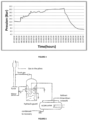
- One line can easily be filled up with liquids, if the segment which has to travel is uphill or at topographical valleys ( Figure 1 A ); the pressure drops ( pressure drops ) coming from this situation contrast with the production pressure at the well head. If a well is mature by now, the production pressure will be low and the pressure drop due to liquids in the line can cause a considerable production loss or, in the worst case, a well stop.
- the production liquids then can accumulate both at the well bottom (rising of the hydrostatic head) and in gas transportation lines, in absence of separators placed at the well head or, even if the latter are present, should they result to be however inadequate to the total removal of the liquids associated to the gas production.
- foamers foamers
- the traditional use of foamers provides the addition in batches or continuously of the product, which has to be capable of developing the foam after the flow of production gas and the turbulence caused thereby.
- the formed foam lowers the surface tension of the water existing in the pipeline which is then transported, still by the same gas, more easily than the water itself.
- the foam reaches the production field and the main separators where it has to be removed, before entering the separator, with a suitable defoaming additive, with the purpose of avoiding dragging of liquid in the produced gases.
- the pigs are mainly cleaning brushes.
- the materials thereof they are made can be plastics such as polyurethane foam or silicone rubber, or metals such as stainless steel. It seems that the first devices were made of steel and leather and when they slid they emitted strident and scratchy noises, as if inside the pipe there could be animals screeching, consequently the name "pig”.
- the pig is a device which is inserted in a pipeline and it moves along the whole length of the line, thanks to the push given by the production gas or by other propellants (air, water, nitrogen, ...) by cleaning and emptying the pipeline itself.
- the amount of accumulations of gas pollutants (sand, water, precipitated salts, liquid and solid hydrocarbons such as paraffin, etc.) on the inner walls of the pipelines starts to create occlusions, this cleaning device is launched.
- gas pollutants sand, water, precipitated salts, liquid and solid hydrocarbons such as paraffin, etc.
- the essential condition for using pigs then is the presence of a launch station, wherein the pig is inserted, and an arrival station (which in case of loop can coincide with the launch one) wherein the pig will wait for being re-used.
- an arrival station which in case of loop can coincide with the launch one
- the valves existing in the "piggable" lines have to allow the pig passage without creating inhomogeneities with the remaining portion of the line or representing an obstacle or a shrinkage which can be hardly overcome by the pad.
- the pig technology is very effective and little risky if it is applied on a new line and it is fitted to the correct use of the technology itself: however, some outdated lines, worn by time, even if at the beginning are "piggable", they have no more safety and sliding conditions required to apply this technique. Should the occlusions in some tracts be too consolidated, or should the line geometry have changed due to a series of mechanical operations over the system life, this mechanical treatment becomes risky and it cannot be used.
- the object of the present invention is to provide a new technology which overcomes the disadvantages of the known techniques and which is overall advantageous with respect thereto.
- the present invention which is defined by the appended claims, practically joins the technology of the foamers ( foamer ) with that of the launch of the pig, in which the new idea is represented by the formation of a pig formed by a foam cushion, arranged inside the pipeline and produced by using water, surfactant and the same production gas. Under pig foam a piston or pad of dense, compact and sufficiently consistent foam is meant.
- the foam which has formed in fact can have the consistency and the resistance of a real pig and it is capable of moving small accumulations of sediments, but, above all, all liquids accumulated and included in the pipeline by acting as a piston. Then, its cleaning and removing effect is obtained by means of a mechanical push rather than through the mechanisms underlying the techniques with foamers described in the prior art, that is decrease in the surface tension of accumulated water and integration of the same water in the foam then dragged towards the end of the pipeline.
- the present invention is defined in claim 1 and relates to: a method for the removal of deposits accumulated in the pipelines for the production and/or transportation of gas characterized by the following steps:
- the foam cushion is produced in situ in the pipeline or is produced externally to the pipeline and subsequently introduced in the pipeline.
- the foam cushion is produced by mixing in a solvent selected from water, aqueous solution or organic solution one or more surfactants and gas or air.
- the surfactant is selected from: oxyethylated surfactants, oxyethylated phenols, oxyethylated fatty acids, oxyethylated alkyl monoethanolamides, lauryl beta imino-propionates, oxy-ethylene oxy-propylene copolymers, anionic surfactants, acid surfactants, basic or amphoteric surfactants or solid soaps.
- the suitable means to produce the foam cushion is selected from: a mixer, a pump for the water/product mixture, having high flow rate and high operating pressures, an orifice or nozzle, a pressure reducer ( figure 3 ).
- the invention relates to a foaming agent comprising, or consisting of, a surfactant selected from oxyethylated surfactants, oxyethylated phenols, oxyethylated fatty acids, oxyethylated alkyl monoethanolamides, lauryl beta imino-propionates, oxy-ethylene oxy-propylene copolymers, anionic surfactants, acid surfactants, basic or amphoteric surfactants or solid soaps in a method according to anyone of claims 1 to 3 and 7 to 10, for the preparation of a foam cushion.
- a surfactant selected from oxyethylated surfactants, oxyethylated phenols, oxyethylated fatty acids, oxyethylated alkyl monoethanolamides, lauryl beta imino-propionates, oxy-ethylene oxy-propylene copolymers, anionic surfactants, acid surfactants, basic or amphoteric surfact
- the invention relates to the use of a foaming agent comprising, or consisting of, a surfactant selected from oxyethylated surfactants, oxyethylated phenols, oxyethylated fatty acids, oxyethylated alkyl monoethanolamides, lauryl beta imino-propionates, oxy-ethylene oxy-propylene copolymers, anionic surfactants, acid surfactants, basic or amphoteric surfactants or solid soaps in a method according to anyone of claims 1 to 3 and 7 to 10, for the preparation of a foam cushion.
- a surfactant selected from oxyethylated surfactants, oxyethylated phenols, oxyethylated fatty acids, oxyethylated alkyl monoethanolamides, lauryl beta imino-propionates, oxy-ethylene oxy-propylene copolymers, anionic surfactants, acid surfactants, basic or amphoter
- an industrial plant for the gas production and/or transportation comprising a pipeline for the gas transportation, equipped with means for generating a foam cushion inside the pipeline itself and suitable for the removal of deposits which impede the gas flow through the pipeline.
- the means for the production of the foam cushion is represented by at least one segment of the pipeline itself (segregable) isolable from the rest of the pipeline by a first upstream valve and a second downstream valve and provided with at least one external valve for opening to the atmosphere for venting the internal gases and for loading a foaming agent and at least one valve cut-off, that is a side tube having small section, for the insertion of an instrument (thermometer, pressure gauge, ...) or for gas sampling, said isolable segment being upstream of the pipeline area obstructed by deposits.
- the plant can be a refinery, comprising means for the production of the foam cushion described in the present invention for the drainage of the lines transporting gas inside said plant between an operating phase and the subsequent one.
- the present invention relates to the use of a foam cushion as described and defined in the present description and claims, for handling unwished gases which can accumulate in the tubes of industrial plants and/or for the drainage of said pipelines.
- the means for generating a foam cushion can be foam production means external and in parallel with respect to the pipeline itself comprising an instrument suitable for the foam production and a pipeline for introducing the foam in the main line.
- the unwished gases can be natural gases, a not limiting example thereof is represented by methane and/or propane, or they can be gases which develop in the plant after refining processes (herein defined even as "process gases") a not limiting example thereof is represented by propane, butane, hydrogen sulphide, mercaptans and other gases known to the person skilled in the art.
- the foam forming procedures are very simple: mainly a line section, which can be segregated from the remaining portion of the system, or an external foam production plant or apparatus can be used.
- This mechanism involves then long periods of time and the water arrives in the final station very diluted over time, in a period which can reach several days.
- the use of the "foam cushion” results to have several advantages with respect to the classical techniques.
- With respect to the continuous additivation of the foamer it has a much shorter duration in time, it reduces drastically the quantity of required surfactant and it is much more effective.
- With respect to the use of the mechanical pig it results to be less invasive, it can be performed on all ducts, even on the mechanically not piggable ones, in much shorter periods of time, by allowing a much more reduced production standstill, and it cancels any risk of mechanical damages caused by dragging of classical pig during the travel in pipeline.
- the advantages in terms of time and cost are very considerable, since it can be applied in few hours and by involving very few personnel.
- An additional advantage of the present invention is given by the use of the new technique of foam cushion provided in the present description even in the lines which transport gases inside a refinery.
- this technique is useful for draining the blow down (blow down) circuit and torch.
- This portion of the refinery plants is necessary as the pressure recipients of the refinery itself are constructed in order to withstand a prefixed inner pressure. Should the inner pressure overcome the pre-established value, the exceeding gas is evacuated through suitably calibrated safety valves; the discharge in atmosphere is not advisable since the vapours and gases can be toxic and impact with surrounding environment, then the discharge in torch allows to reduce quickly and safely the pressure of the plants in case of emergency.
- the torch or flame) burns the possible gas excess produced by the plants with respect to the requirements of furnaces, as well as the gas surplus produced during the not regular running of the plant (start, stop, malfunctions).
- the discharge circuit and torch including a series of very long lines, having great sizes, carrying indeed gases to the flame, is polluted by a series of by-products transported by the discharge gases, such as sulphurs, H 2 S, mercaptans, light hydrocarbon compounds and carbon residues.
- the fluids usually used for drainages are nitrogen and water vapour.
- the invention illustrated in this patent is new and particularly useful in case of drainage of the refinery discharge lines: the removal of the gases from the line often is low and little effective if performed with nitrogen or vapour, it involves the use of huge amounts of these fluids for very long periods of time (several days).
- a foam pig foam cushion formed with water, surfactant and gas which in this case will be nitrogen, allows the real removal of various gases and pollutants inside the lines, quickly and with maximum effectiveness.
- the preferably used gas for forming foam is nitrogen: the formed foam cushion could be pushed always by nitrogen as carrier or by high or medium pressure vapour.
- the surfactants used to form the foam will help even in cleaning the line, by favouring the removal of the liquid and solid pollutants.
- the foam can be used as transportation carrier for other substances compatible with the foam itself and useful in cleaning and decontamination, as solvents and oxidants (amines-oxide, various peroxides in particular persulphate and percarbonate).
- solvents and oxidants amines-oxide, various peroxides in particular persulphate and percarbonate.
- upstream and downstream are to be referred to the direction of the gas stream flowing from the well outlet or head towards a peripheral station.
- the two expressions identify a position preceding or following another position on the line, respectively.
- Suitable acid surfactants are: coco-carboxypropionic acid, acrylic acid/dimethyl-diallyl ammonium chloride copolymer, coconut trimethyl ammonium chloride, C9-11 alkyl (linear)-alcohol alkoxy sulphate, C6-10 alkyl (linear)-alcohol alkoxy sulphate, triethyleneglycol-monohexyl-ether sulfate, C14-16 alpha olefin sulfonate, ethylenediamine tetra acetic acid trisodium salt, oleic acid, dodecanoic acid, coconut acid, octadecanoic acid, lauryl acid, myristic acid, hexadecanoic acid, octanoic acid.
- Suitable basic surfactants are: coco-dimethylamine-oxide, cocot-amidopropyl sulfo betaine, coconut-amidopropyl betaine, coconut-amidopropyl amine oxide, tall oil bis-hydroxyethyl glycinate, coco-diethanolamide, oleic acid diethanolamide, coco-N,N-bis-hydroxyethyl amide, oxyethylated coco-amine, laurylamine oxide, dihydroxy ethyl C12-15 alkoxypropyl amine oxide.
- amphoteric surfactants suitable to the invention can be: coco-ampho-acetate, coco-ampho-propionate, coco-ampho-hydroxypropyl sulfonate, lauryl-ampho-acetate, lauryl-ampho-dipropionate, capryl-ampho-diacetate, sodium lauryl-imino propionate, disodium talloil iminodipropionate, stearyl ampho-propyl sulphonate.
- ampho means amphoteric that is a substance which can behave with acid or basic characteristics depending upon the substance therewith it can interact and it designates the presence of an additional ammonium or nitrogen group in the corresponding molecule or formula of the shown surfactant. For example ammonium, imino, imidazole or equivalents, conferring the amphotericity feature.
- coco-carboxypropionic acid acrylic acid/dimethyl-diallyl ammonium chloride copolymer, coconut trimethyl ammonium chloride, C9-11 alkyl (linear)-alcohol alkoxy sulphate, C6-10 alkyl (linear)-alcohol alkoxy sulphate, triethyleneglycol-monohexyl-ether sulfate, C14-16 alpha olefin sulfonate, ethylenediamine tetra acetic acid trisodium salt, oleic acid, dodecanoic acid, coconut acid, octadecanoic acid, lauryl acid, myristic acid, hexadecanoic acid, octanoic acid, coco-dimethylamine-oxide, cocot-amidopropyl sulfo betaine, coconut-amidopropyl betaine
- high-density foam having consistency suitable for preparing a foam cushion is performed under the following conditions: water/foamer ratio from 1:3 to 1:1; foam density ranging from 0.1 g/ml and 0.5 g/ml.
- the foam quantity required for each foam cushion launch depends upon the diameter of the pipeline and provides the use of few tens of litres (10, 20, 30) of water/foamer mixture to some hundreds of litres with the purpose of producing some cubic meters of foam (for example 1 to 20).
- the method of the invention provides two possible implementation modes.
- the pipeline line has at least a section of some tens of meters, for example 10, 15, 20, 30 meters, which could be isolated from the remaining portion, positioned in the initial portion, that is little next the well head or however upstream with respect to the areas which have to be cleaned, that is the areas which can accumulate liquids or obstruct with debris.
- the isolated segment then has to be equipped with one or more valves for closing the well head, which delimit it upstream and which determine the beginning of the segment and it must have a closing valve which delimits it downstream of the initial one, as said at the distance of 10-30 meters (also depending upon the line diameter).
- the isolated segment has to be provided with at least one external valve for opening to the atmosphere required for venting the gas remained trapped with consequent drainage of the segment itself.
- the segment will equally include at least one valve cut-off for the insertion of an instrument (thermometer, pressure gauge, etc) or for gas sampling and for inserting the foaming agent or the foam preformed according to the embodiment of the invention.
- the plant can provide two or more segments which can be isolated in series, as above described, for the sequential production of two or more foam cushions which will reach the line end separator independently.
- This type of plant provides the in-situ production of foams.
- the procedure for creating the foam can be schematized in few essential steps described by way of example:
- the monitored parameters were: Quantity, quality and persistence of the produced foam. All tests were performed the conditions being equal, except for the variability in the Water-Product ratio which reproduces the ratios which can be those used in the field.
- the following table shows the tests carried out upon varying the ratio Water/CH Phoenix 6163 (mixture of not ionic surfactants) with the related comments about quantity and quality of the produced foam.
- the foam pig effectiveness results to be maximum if the isolated pipeline section will be completely filled-up, without leaving empty spaces in the upper portion of the pipeline.
- the result will be the production of a very consistent foam, formed by the production gas trapped in bubbles in the water thanks to the presence of surfactant which increases the liquid surface tension.
- the foam will fill-up fully a quite extended line section, much more extended than the segment used for introducing the liquids.
- the so formed foam cushion behaves like a "chemical pig” or " foam pig” that is like a plunger and, pushed by the gas pressure, it will be able to move water and any debris accumulated along the pipeline line.
- the foam is produced externally with respect the line of pipes with means such as an autonomous apparatus, device or plant, placed parallelly with respect to the line and introduced in the line through a suitable shut-off, arranged for instruments or samplings.
- the external means for producing the foam can be any device suitable for the foam production such as: a mixer, a high rate and high operating pressure pump and an aperture or a nozzle or any other method suitable to the foam production.
- Said external means usually is inserted in a line in parallel as schematized by way of example in figures, but it could have even another geometry.
- the present description provides examples of the industrial plants suitable to implement the method of the invention.
- the industrial plant is a plant for the production and/or transportation of natural or process gases, as above defined, comprising a pipeline for the transportation of gas or pipeline, equipped with means for generating a foam cushion inside the pipeline itself and suitable for the removal of deposits which impede the gas flow through the pipeline.
- said plant is an oil-refining plant, equipped with the means for generating a foam cushion inside the pipeline of the discharge circuit of said plant and suitable to drainage of said pipeline which is performed between a refining operating cycle and the subsequent one as described above.
- drainage as said above, the removal of exceeding gaseous residues is meant which have accumulated in the discharge pipeline ahead of the torch combustion area as described above.
- the means for generating the foam cushion is represented at least by one segment of the pipeline itself (segregable) isolable from the rest of the pipeline and limited by an initial valve for closing the flow upstream and a final valve for closing downstream and provided with at least one external valve for opening to the atmosphere for venting the internal gases and for loading a foaming agent.
- the isolable pipeline segment has a length ranging from 5 and 40 meters, even depending upon the diameter of the pipeline itself, for example 10, 15, 20, 25, 30, 35 meters. Said segment is provided with one or more additional valve cut-offs for the insertion of an instrument (thermometer, pressure gauge, ...) or for gas sampling.
- an instrument thermometer, pressure gauge, ...) or for gas sampling.
- the plant can comprise two or more isolable segments as described above in subsequent series separated from one another by a closing valve.
- the pipeline does not require an isolable segment, but the means for generating the foam cushion is foam production means external and in parallel with respect to the pipeline itself.
- foam production means comprises an apparatus and device suitable for generating the foam and a pipeline for introducing the foam in the main line.
- the external means for generating the foam can be a mixer, a high-flow rate and high operating pressure pump and an aperture or a nozzle.
- the segregable segment as described above for the in-situ production or the plant in parallel for the external production of the foam are usually placed at the beginning of the pipeline near the well head therefrom the gas outflows.
- the shut-off valve well head valve
- the means for producing the foam cushion is placed upstream of the pipeline area obstructed by deposits.
- FIG. 2 Examples of plants according to the invention are illustrated in figure 2 , panel B and 3 panels A and B.
- the purpose of the application is the removal of the water accumulated in the 5 valleys of a line of 15 km: the consequence of the water accumulation in line is the limitation of the gas production due to the accumulated liquid which causes an additional pressure drop.
- the application result depends upon the selection of the suitable product.
- the used product was properly selected with (above-described) laboratory test, both as chemical composition, and for the volume/volume ratios to be kept between product and water additioned in the line, that is water/foamer ratio ranging from 1:3 to 1:1; foam density ranging from 0.1 g/ml and 0.5 g/ml.
- CHIMEC anti-foaming agent is required for controlling the possible negative effects of the foam and to protect the plant and in particular the separator inletting the central station, having limited volume.
- each batch consists of foaming agent and water in ratio 2:1.
- the total loaded liquids are about 120 litres of product Chimec Phoenix 6163 and about 60 litres of water.
- the foam cushion was generated by external means, described in the above-illustrated scheme ( Figure 3 , panels A and B).
- the used amounts of water and product are more or less the same of example 1, but clearly it was not necessary to open and drain the line stump.
- shut-off valve is required to stop the production (which is always present in any gas field) and a shut-off (for example an instrument socket) for introducing the foam.
- a refinery discharge line having sizes equal to 76.2 mm (three inches), was drained by using the foam cushion procedure.
- the line had a significant length (greater than 150 m) and had two valleys having big sizes. Then it was necessary to control the behaviour of the foam during the passage of the valleys (water hammer phenomenon, pressure drop, foam drop).
- the application was very positive, it showed that the line route is not an obstacle, no problem for the foam cushion to go along the two valleys, the foam was collected in the final container without difficulty. No excessive odour or heat, no hot effluent, complete removal of the pyrophoric risk.
- the line was cleaned perfectly and the drainage allowed to perform the maintenance work by performing even hot weldings, without additional cleaning. An antifoam was present in the final container to neutralize the foam.
Landscapes
- Engineering & Computer Science (AREA)
- Chemical & Material Sciences (AREA)
- General Engineering & Computer Science (AREA)
- Mechanical Engineering (AREA)
- Combustion & Propulsion (AREA)
- Dispersion Chemistry (AREA)
- Physics & Mathematics (AREA)
- Fluid Mechanics (AREA)
- Life Sciences & Earth Sciences (AREA)
- General Life Sciences & Earth Sciences (AREA)
- Materials Engineering (AREA)
- Organic Chemistry (AREA)
- Cleaning In General (AREA)
- Detergent Compositions (AREA)
- Pipeline Systems (AREA)
- Gas Separation By Absorption (AREA)
Claims (15)
- Verfahren für die Entfernung von Ablagerungen, die sich in den Rohrleitungen einer Produktion und/oder eines Transports von Erd- und/oder Prozessgasen angesammelt haben, umfassend die folgenden Schritte:a) der Gasstrom entlang der Rohrleitung wird durch ein Absperrventil blockiert;b) ein kompaktes Schaumkissen wird bereitgestellt, das einen Abschnitt der Rohrleitung stromabwärts des Absperrventils und stromaufwärts des Abschnitts, der die Ablagerungen enthält, vollständig ausfüllt;der Gasstrom, der das Schaumkissen entlang der Rohrleitung schiebt, das die Ablagerungen mit sich trägt, wird reaktiviert, wobei das Schaumkissen durch Mischen von einem oder mehreren Tensiden und Gas oder Luft in einem Lösungsmittel produziert wird, das aus Wasser, einer wässrigen Lösung oder einer organischen Lösung ausgewählt ist.
- Verfahren nach Anspruch 1, wobei die Ablagerungen Ablagerungen von Wasser und/oder Kondensatmaterialien sind.
- Verfahren nach Anspruch 1 oder 2, wobei das Schaumkissen in situ in der Pipeline produziert wird oder außerhalb der Pipeline produziert und anschließend in die Pipeline eingeführt wird.
- Verfahren nach Anspruch 3, wobei das Tensid ausgewählt ist aus:
oxyethylierten Tensiden, oxyethylierten Phenolen, oxyethylierten Fettsäuren, oxyethylierten Alkylmonoethanolamiden, Lauryl-beta-iminopropionaten, Oxyethylen-Oxypropylen-Copolymeren, anionischen Tensiden, sauren Tensiden, basischen oder amphoteren Tensiden oder festen Seifen. - Verfahren nach Anspruch 4, wobei die sauren Tenside ausgewählt sind aus: Kokoscarboxypropionsäure, Acrylsäure/Dimethyl-Diallyl-Ammoniumchlorid-Copolymer, Kokosnusstrimethylammoniumchlorid, C9-11-Alkyl-(linearer)-Alkohol-Alkoxysulfat, C6-10-Alkyl (linearer)-Alkohol-Alkoxysulfat, Triethylenglykolmonohexylethersulfat, C14-16-Alpha-Olefinsulfonat, Ethylendiamintetraessigsäuretrinatriumsalz, Olsäure, Dodecansäure, Kokosnusssäure, Octadecansäure, Laurylsäure, Myristinsäure, Hexadecansäure, Octansäure, Kokosdimethylaminoxid, Kokosamidopropylsulfobetain, Kokosnussamidopropylbetain, Kokosnussamidopropylaminoxid, Tallöl-bishydroxyethylglycinat, Kokosdiethanolamid, Ölsäurediethanolamid, Kokos-N,N-bis-hydroxyethylamid, oxyethyliertem Kokosamin, Laurylaminoxid, Dihydroxyethyl-C12-15-alkoxypropylaminoxid, Kokosamphoacetat, Kokosamphopropionat, Kokosamphohydroxypropylsulfonat, Laurylamphoacetat, Laurylamphodipropionat, Caprylamphodiacetat, Natriumlauryliminopropionat, Dinatriumtallöliminodipropionat, Stearylamphopropylsulfonat.
- Verfahren nach Anspruch 3, wobei das Schaumkissen in situ in der Pipeline produziert wird und das Verfahren die folgenden Schritte umfasst:- ein Abschnitt der Rohrleitung wird durch ein Anfangsventil und ein Endventil isoliert, das den stromabwärtigen Abschnitt begrenzt;- er wird in dem abgetrennten Bereich durch Vermindern seines Drucks auf Atmosphärendruck entlüftet;- der abgetrennte Leitungsabschnitt wird mit einer Mischung aus Wasser und Schaummittel gefüllt;- das Anfangsventil wird stromaufwärts des abgetrennten Abschnitts geöffnet;- das Endventil wird stromabwärts des abgetrennten Segments durch Erzeugen einer starken Turbulenz stromabwärts des Ventils geöffnet, die das Schubgas mit dem Wasser und dem Tensid in der Lösung innig mischt;- dem Gasdruck wird ermöglicht, das Schaumkissen entlang der Rohrleitung zu schieben und das Schaumkissen schiebt das Wasser und beliebige angesammelte Ablagerungen nach oben zu einer Sammelstation.
- Verfahren nach Anspruch 6, wobei die Abfolge aller Schritte zwei- oder mehrmals wiederholt wird.
- Verfahren nach Anspruch 3, wobei das Schaumkissen außerhalb der Rohrleitung produziert wird und das Verfahren die folgenden Schritte umfasst:- die Rohrleitung wird stromaufwärts des Abschnitts, der die Ablagerungen enthält, mittels eines Absperrventils verschlossen;- das Schaumkissen wird außerhalb der Rohrleitung durch ein geeignetes Mittel produziert;- das Schaumkissen wird über eine Seitenladeleitung stromabwärts des Absperrventils in die Rohrleitung eingeführt;- das Absperrventil wird wieder vollständig geöffnet;- dem Gasdruck wird ermöglicht, das Schaumkissen entlang der Rohrleitung zu schieben und das Schaumkissen schiebt das Wasser und beliebige angesammelte Ablagerungen nach oben zu einer Sammelstation.
- Verfahren nach Anspruch 8, wobei das geeignete Mittel, um das Schaumkissen zu produzieren, ausgewählt ist aus: einem Mischer, einer Pumpe mit hoher Liefermenge und hohem Betriebsdruck, einer Öffnung oder Düse, einem Druckminderer.
- Schaummittel, umfassend oder bestehend aus einem Tensid, das aus oxyethylierten Tensiden, oxyethylierten Phenolen, oxyethylierten Fettsäuren, oxyethylierten Alkylmonoethanolamiden, Lauryl-beta-iminopropionaten, Oxyethylen-Oxypropylen-Copolymeren, anionischen Tensiden, sauren Tensiden, basischen oder amphoteren Tensiden oder festen Seifen ausgewählt ist, in einem Verfahren nach einem der Ansprüche 1 bis 3 und 7 bis 9 zum Herstellen eines kompakten Schaumkissens.
- Schaummittel nach Anspruch 10, wobei das Tensid ausgewählt ist aus: Kokoscarboxypropionsäure, Acrylsäure/Dimethyl-Diallyl-Ammoniumchlorid-Copolymer, Kokosnusstrimethylammoniumchlorid, C9-11-Alkyl-(linearer)-Alkohol-Alkoxysulfat, C6-10-Alkyl (linearer)-Alkohol-Alkoxysulfat, Triethylenglykolmonohexylethersulfat, C14-16-Alpha-Olefinsulfonat, Ethylendiamintetraessigsäuretrinatriumsalz, Olsäure, Dodecansäure, Kokosnusssäure, Octadecansäure, Laurylsäure, Myristinsäure, Hexadecansäure, Octansäure, Kokosdimethylaminoxid, Kokosamidopropylsulfobetain, Kokosnussamidopropylbetain, Kokosnussamidopropylaminoxid, Tallöl-bishydroxyethylglycinat, Kokosdiethanolamid, Ölsäurediethanolamid, Kokos-N,N-bis-hydroxyethylamid, oxyethyliertem Kokosamin, Laurylaminoxid, Dihydroxyethyl-C12-15-alkoxypropylaminoxid, Kokosamphoacetat, Kokosamphopropionat, Kokosamphohydroxypropylsulfonat, Laurylamphoacetat, Laurylamphodipropionat, Caprylamphodiacetat, Natriumlauryliminopropionat, Dinatriumtallöliminodipropionat, Stearylamphopropylsulfonat.
- Schaummittel nach einem der Ansprüche 10 oder 11, umfassend Wasser und Tensid in Wasser/Tensid-Verhältnissen von 1 : 3 bis 1 : 1, wobei das Tensid ausgewählt ist aus Kokoscarboxypropionsäure, Acrylsäure/Dimethyl-Diallyl-Ammoniumchlorid-Copolymer, Kokosnusstrimethylammoniumchlorid, C9-11-Alkyl-(linearer)-Alkohol-Alkoxysulfat, C6-10-Alkyl (linearer)-Alkohol-Alkoxysulfat, Triethylenglykolmonohexylethersulfat, C14-16-Alpha-Olefinsulfonat, Ethylendiamintetraessigsäuretrinatriumsalz, Ölsäure, Dodecansäure, Kokosnusssäure, Octadecansäure, Laurylsäure, Myristinsäure, Hexadecansäure, Octansäure, Kokosdimethylaminoxid, Kokosamidopropylsulfobetain, Kokosnussamidopropylbetain, Kokosnussamidopropylaminoxid, Tallöl-bishydroxyethylglycinat, Kokosdiethanolamid, Ölsäurediethanolamid, Kokos-N,N-bis-hydroxyethylamid, oxyethyliertem Kokosamin, Laurylaminoxid, Dihydroxyethyl-C12-15-alkoxypropylaminoxid, Kokosamphoacetat, Kokosamphopropionat, Kokosamphohydroxypropylsulfonat, Laurylamphoacetat, Laurylamphodipropionat, Caprylamphodiacetat, Natriumlauryliminopropionat, Dinatriumtallöliminodipropionat, Stearylamphopropylsulfonat.
- Verwendung eines Schaummittels, umfassend oder bestehend aus einem Tensid, das aus oxyethylierten Tensiden, oxyethylierten Phenolen, oxyethylierten Fettsäuren, oxyethylierten Alkylmonoethanolamiden, Lauryl-beta-iminopropionaten, Oxyethylen-Oxypropylen-Copolymeren, anionischen Tensiden, sauren Tensiden, basischen oder amphoteren Tensiden oder festen Seifen ausgewählt ist, in einem Verfahren nach einem der Ansprüche 1 bis 3 und 7 bis 9 für die Herstellung eines Schaumkissens.
- Verwendung nach Anspruch 13, wobei das Tensid ausgewählt ist aus: Kokoscarboxypropionsäure, Acrylsäure/Dimethyl-Diallyl-Ammoniumchlorid-Copolymer, Kokosnusstrimethylammoniumchlorid, C9-11-Alkyl-(linearer)-Alkohol-Alkoxysulfat, C6-10-Alkyl (linearer)-Alkohol-Alkoxysulfat, Triethylenglykolmonohexylethersulfat, C14-16-Alpha-Olefinsulfonat, Ethylendiamintetraessigsäuretrinatriumsalz, Ölsäure, Dodecansäure, Kokosnusssäure, Octadecansäure, Laurylsäure, Myristinsäure, Hexadecansäure, Octansäure, Kokosdimethylaminoxid, Kokosamidopropylsulfobetain, Kokosnussamidopropylbetain, Kokosnussamidopropylaminoxid, Tallöl-bishydroxyethylglycinat, Kokosdiethanolamid, Ölsäurediethanolamid, Kokos-N,N-bis-hydroxyethylamid, oxyethyliertem Kokosamin, Laurylaminoxid, Dihydroxyethyl-C12-15-alkoxypropylaminoxid, Kokosamphoacetat, Kokosamphopropionat, Kokosamphohydroxypropylsulfonat, Laurylamphoacetat, Laurylamphodipropionat, Caprylamphodiacetat, Natriumlauryliminopropionat, Dinatriumtallöliminodipropionat, Stearylamphopropylsulfonat.
- Verwendung eines Schaumkissens, das wie in den Ansprüchen 1 bis 9 beschrieben produziert wird, für die Entfernung von unerwünschten Gasen, die in den Rohrleitungen von Industrieanlagen vorhanden sind, und/oder für die Drainage der Rohrleitungen.
Applications Claiming Priority (2)
| Application Number | Priority Date | Filing Date | Title |
|---|---|---|---|
| IT201800001388A IT201800001388A1 (it) | 2018-01-19 | 2018-01-19 | Metodo di rimozione di depositi accumulati nelle condotte di trasporto di gas naturali |
| PCT/IB2019/050259 WO2019142083A1 (en) | 2018-01-19 | 2019-01-14 | Method for the removal of deposits accumulated in the pipelines of transport of gas |
Publications (3)
| Publication Number | Publication Date |
|---|---|
| EP3740329A1 EP3740329A1 (de) | 2020-11-25 |
| EP3740329B1 true EP3740329B1 (de) | 2025-04-16 |
| EP3740329C0 EP3740329C0 (de) | 2025-04-16 |
Family
ID=62002264
Family Applications (1)
| Application Number | Title | Priority Date | Filing Date |
|---|---|---|---|
| EP19703190.9A Active EP3740329B1 (de) | 2018-01-19 | 2019-01-14 | Verfahren zum entfernen von in den rohrleitungen zum transport von gas angesammelten ablagerungen |
Country Status (6)
| Country | Link |
|---|---|
| US (1) | US20200368794A1 (de) |
| EP (1) | EP3740329B1 (de) |
| EA (1) | EA202091498A1 (de) |
| IT (1) | IT201800001388A1 (de) |
| SG (1) | SG11202005113UA (de) |
| WO (1) | WO2019142083A1 (de) |
Families Citing this family (5)
| Publication number | Priority date | Publication date | Assignee | Title |
|---|---|---|---|---|
| WO2022234551A1 (en) * | 2021-05-05 | 2022-11-10 | Almasi Pezhman | Draining and cleaning pig for oil, gas, and petrochemical pipelines |
| US20230105967A1 (en) * | 2021-10-01 | 2023-04-06 | Cnx Resources Corporation | Fluid purging system |
| CN113980663B (zh) * | 2021-11-10 | 2022-08-16 | 四川大学 | 一种耐高温自发泡膨胀硅橡胶堵漏材料及其制备方法 |
| EP4638638A1 (de) * | 2022-12-20 | 2025-10-29 | Chimec S.p.A. | Neues schäumungsmittel mit hoher thermischer stabilität und biokompatibilität |
| CN119926923B (zh) * | 2025-04-08 | 2025-06-17 | 浙江大学长三角智慧绿洲创新中心 | 一种双层环状改性冰浆清洗供水管道的方法 |
Family Cites Families (8)
| Publication number | Priority date | Publication date | Assignee | Title |
|---|---|---|---|---|
| US4968332A (en) * | 1989-05-08 | 1990-11-06 | Maher Thomas P | Separator unit |
| US5127961A (en) * | 1990-12-14 | 1992-07-07 | Naylor Industrial Services, Inc. | Method and apparatus for forming a frothed fluid slug for pipe cleaning |
| US5385206A (en) * | 1993-01-21 | 1995-01-31 | Clearwater, Inc. | Iterated foam process and composition for well treatment |
| US6802909B1 (en) * | 2003-04-24 | 2004-10-12 | Doyle J. Crenshaw | Method for improving the operation of a pipeline by employing soap pigs |
| US20080099946A1 (en) * | 2006-10-31 | 2008-05-01 | Chevron U.S.A. Inc. | Foam for mitigation of flow assurance issues in oil & gas systems |
| US20090321077A1 (en) * | 2007-01-30 | 2009-12-31 | Norman David A | Pigging Of Flowlines By In-Situ Generated Foam Pigs |
| US7422064B1 (en) * | 2007-03-05 | 2008-09-09 | Baker Hughes Incorporated | High performance foams for unloading gas wells |
| EP2504408A2 (de) * | 2009-11-25 | 2012-10-03 | DSM IP Assets B.V. | Polyesteramid-schaumbildner |
-
2018
- 2018-01-19 IT IT201800001388A patent/IT201800001388A1/it unknown
-
2019
- 2019-01-14 WO PCT/IB2019/050259 patent/WO2019142083A1/en not_active Ceased
- 2019-01-14 EA EA202091498A patent/EA202091498A1/ru unknown
- 2019-01-14 SG SG11202005113UA patent/SG11202005113UA/en unknown
- 2019-01-14 EP EP19703190.9A patent/EP3740329B1/de active Active
- 2019-01-14 US US16/961,199 patent/US20200368794A1/en not_active Abandoned
Also Published As
| Publication number | Publication date |
|---|---|
| IT201800001388A1 (it) | 2019-07-19 |
| SG11202005113UA (en) | 2020-06-29 |
| EA202091498A1 (ru) | 2020-10-09 |
| WO2019142083A1 (en) | 2019-07-25 |
| EP3740329A1 (de) | 2020-11-25 |
| US20200368794A1 (en) | 2020-11-26 |
| EP3740329C0 (de) | 2025-04-16 |
Similar Documents
| Publication | Publication Date | Title |
|---|---|---|
| EP3740329B1 (de) | Verfahren zum entfernen von in den rohrleitungen zum transport von gas angesammelten ablagerungen | |
| US6234183B1 (en) | Method for removing deposits comprising heavy hydrocarbonaceous materials and finely divided inorganic materials from a flow line using a surfactant composition | |
| US5977032A (en) | Acidic surfactant composition and method for cleaning wellbore and flowline surfaces using the surfactant composition | |
| DE602004006643T2 (de) | Verfahren und system zum spritzen von behandlungsfluid in ein bohrloch | |
| RU2169752C2 (ru) | Чистящая композиция, способ очистки нефтяных и газовых скважин, трубопроводов, обсадных труб и продуктивных пластов, способ выделения избыточной воды, осадка или их обоих из добытой сырой нефти и способ гидравлического разрыва пласта | |
| US3637021A (en) | Method and apparatus for removal of petroliferous adherent solids from an inaccessible surface | |
| CA2621125C (en) | A process for foaming a wet hydrocarbon composition | |
| ITMI20100695A1 (it) | Procedimento per la rimozione di depositi da un pozzo a olio o a gas, e/o dalle strutture di superficie, e/o dalle apparecchiature ad esso correlate, e/o da formazioni contenenti idrocarburi | |
| US3722594A (en) | Well methods using small diameter tubing | |
| SA112340046B1 (ar) | تركيبات وطرق لاستخلاص محسّن للهيدروكربون | |
| US20030217956A1 (en) | Methods and apparatus for separating fluids | |
| NO163340B (no) | Behandling av gassbaerende formasjoner under havoverflatenfor aa redusere vannproduksjonen. | |
| US20220177773A1 (en) | Reverse emulsion for hydraulic fracturing | |
| US8430161B2 (en) | Mitigation of elemental sulfur deposition during production of hydrocarbon gases | |
| US9605513B1 (en) | Method of gas, oil and mineral production using a clean processing system and method | |
| KR101994436B1 (ko) | 유류로 오염된 토양오염 정화방법 및 그 시스템 | |
| US2998066A (en) | Method of treating wells | |
| US9631134B2 (en) | Subterranean well treatment system | |
| JP4628412B2 (ja) | 井戸の洗浄方法および洗浄装置 | |
| NO302840B1 (no) | Fremgangsmåte ved behandling av sandstensformasjoner | |
| US3583489A (en) | Well cleaning method using foam containing abrasives | |
| EA041429B1 (ru) | Способ удаления отложений, накапливающихся в трубопроводе для транспортировки газа | |
| RU2531957C1 (ru) | Способ очистки скважины от асфальтосмолопарафиновых отложений | |
| CA2667975A1 (en) | Foam for mitigation of flow assurance issues in oil and gas systems | |
| NO872553L (no) | Fortrengning av frie fluidansamlinger i rledninger. |
Legal Events
| Date | Code | Title | Description |
|---|---|---|---|
| STAA | Information on the status of an ep patent application or granted ep patent |
Free format text: STATUS: UNKNOWN |
|
| STAA | Information on the status of an ep patent application or granted ep patent |
Free format text: STATUS: THE INTERNATIONAL PUBLICATION HAS BEEN MADE |
|
| PUAI | Public reference made under article 153(3) epc to a published international application that has entered the european phase |
Free format text: ORIGINAL CODE: 0009012 |
|
| STAA | Information on the status of an ep patent application or granted ep patent |
Free format text: STATUS: REQUEST FOR EXAMINATION WAS MADE |
|
| 17P | Request for examination filed |
Effective date: 20200804 |
|
| AK | Designated contracting states |
Kind code of ref document: A1 Designated state(s): AL AT BE BG CH CY CZ DE DK EE ES FI FR GB GR HR HU IE IS IT LI LT LU LV MC MK MT NL NO PL PT RO RS SE SI SK SM TR |
|
| AX | Request for extension of the european patent |
Extension state: BA ME |
|
| RIN1 | Information on inventor provided before grant (corrected) |
Inventor name: ALLEGRUCCI, ALESSANDRO Inventor name: QUARANTA, ANDREA Inventor name: BUCCOLINI, MARCO |
|
| DAV | Request for validation of the european patent (deleted) | ||
| DAX | Request for extension of the european patent (deleted) | ||
| STAA | Information on the status of an ep patent application or granted ep patent |
Free format text: STATUS: EXAMINATION IS IN PROGRESS |
|
| 17Q | First examination report despatched |
Effective date: 20221019 |
|
| GRAP | Despatch of communication of intention to grant a patent |
Free format text: ORIGINAL CODE: EPIDOSNIGR1 |
|
| STAA | Information on the status of an ep patent application or granted ep patent |
Free format text: STATUS: GRANT OF PATENT IS INTENDED |
|
| INTG | Intention to grant announced |
Effective date: 20241126 |
|
| GRAS | Grant fee paid |
Free format text: ORIGINAL CODE: EPIDOSNIGR3 |
|
| GRAA | (expected) grant |
Free format text: ORIGINAL CODE: 0009210 |
|
| STAA | Information on the status of an ep patent application or granted ep patent |
Free format text: STATUS: THE PATENT HAS BEEN GRANTED |
|
| AK | Designated contracting states |
Kind code of ref document: B1 Designated state(s): AL AT BE BG CH CY CZ DE DK EE ES FI FR GB GR HR HU IE IS IT LI LT LU LV MC MK MT NL NO PL PT RO RS SE SI SK SM TR |
|
| REG | Reference to a national code |
Ref country code: GB Ref legal event code: FG4D |
|
| REG | Reference to a national code |
Ref country code: CH Ref legal event code: EP Ref country code: DE Ref legal event code: R096 Ref document number: 602019068660 Country of ref document: DE |
|
| REG | Reference to a national code |
Ref country code: IE Ref legal event code: FG4D |
|
| U01 | Request for unitary effect filed |
Effective date: 20250424 |
|
| U07 | Unitary effect registered |
Designated state(s): AT BE BG DE DK EE FI FR IT LT LU LV MT NL PT RO SE SI Effective date: 20250430 |
|
| PG25 | Lapsed in a contracting state [announced via postgrant information from national office to epo] |
Ref country code: ES Free format text: LAPSE BECAUSE OF FAILURE TO SUBMIT A TRANSLATION OF THE DESCRIPTION OR TO PAY THE FEE WITHIN THE PRESCRIBED TIME-LIMIT Effective date: 20250416 |
|
| PG25 | Lapsed in a contracting state [announced via postgrant information from national office to epo] |
Ref country code: NO Free format text: LAPSE BECAUSE OF FAILURE TO SUBMIT A TRANSLATION OF THE DESCRIPTION OR TO PAY THE FEE WITHIN THE PRESCRIBED TIME-LIMIT Effective date: 20250716 Ref country code: GR Free format text: LAPSE BECAUSE OF FAILURE TO SUBMIT A TRANSLATION OF THE DESCRIPTION OR TO PAY THE FEE WITHIN THE PRESCRIBED TIME-LIMIT Effective date: 20250717 |
|
| PG25 | Lapsed in a contracting state [announced via postgrant information from national office to epo] |
Ref country code: PL Free format text: LAPSE BECAUSE OF FAILURE TO SUBMIT A TRANSLATION OF THE DESCRIPTION OR TO PAY THE FEE WITHIN THE PRESCRIBED TIME-LIMIT Effective date: 20250416 |
|
| PG25 | Lapsed in a contracting state [announced via postgrant information from national office to epo] |
Ref country code: HR Free format text: LAPSE BECAUSE OF FAILURE TO SUBMIT A TRANSLATION OF THE DESCRIPTION OR TO PAY THE FEE WITHIN THE PRESCRIBED TIME-LIMIT Effective date: 20250416 |
|
| PG25 | Lapsed in a contracting state [announced via postgrant information from national office to epo] |
Ref country code: RS Free format text: LAPSE BECAUSE OF FAILURE TO SUBMIT A TRANSLATION OF THE DESCRIPTION OR TO PAY THE FEE WITHIN THE PRESCRIBED TIME-LIMIT Effective date: 20250716 |
|
| PG25 | Lapsed in a contracting state [announced via postgrant information from national office to epo] |
Ref country code: IS Free format text: LAPSE BECAUSE OF FAILURE TO SUBMIT A TRANSLATION OF THE DESCRIPTION OR TO PAY THE FEE WITHIN THE PRESCRIBED TIME-LIMIT Effective date: 20250816 |