EP3740051A1 - Waterproof structure for vent hole in electronic equipment, housing, and electronic equipment - Google Patents
Waterproof structure for vent hole in electronic equipment, housing, and electronic equipment Download PDFInfo
- Publication number
- EP3740051A1 EP3740051A1 EP18900347.8A EP18900347A EP3740051A1 EP 3740051 A1 EP3740051 A1 EP 3740051A1 EP 18900347 A EP18900347 A EP 18900347A EP 3740051 A1 EP3740051 A1 EP 3740051A1
- Authority
- EP
- European Patent Office
- Prior art keywords
- filter
- electronic equipment
- housing
- ventilation opening
- waterproof structure
- Prior art date
- Legal status (The legal status is an assumption and is not a legal conclusion. Google has not performed a legal analysis and makes no representation as to the accuracy of the status listed.)
- Granted
Links
Images


Classifications
-
- H—ELECTRICITY
- H05—ELECTRIC TECHNIQUES NOT OTHERWISE PROVIDED FOR
- H05K—PRINTED CIRCUITS; CASINGS OR CONSTRUCTIONAL DETAILS OF ELECTRIC APPARATUS; MANUFACTURE OF ASSEMBLAGES OF ELECTRICAL COMPONENTS
- H05K5/00—Casings, cabinets or drawers for electric apparatus
- H05K5/02—Details
- H05K5/0213—Venting apertures; Constructional details thereof
- H05K5/0215—Venting apertures; Constructional details thereof with semi-permeable membranes attached to casings
-
- H—ELECTRICITY
- H05—ELECTRIC TECHNIQUES NOT OTHERWISE PROVIDED FOR
- H05K—PRINTED CIRCUITS; CASINGS OR CONSTRUCTIONAL DETAILS OF ELECTRIC APPARATUS; MANUFACTURE OF ASSEMBLAGES OF ELECTRICAL COMPONENTS
- H05K5/00—Casings, cabinets or drawers for electric apparatus
- H05K5/02—Details
- H05K5/03—Covers
-
- H—ELECTRICITY
- H05—ELECTRIC TECHNIQUES NOT OTHERWISE PROVIDED FOR
- H05K—PRINTED CIRCUITS; CASINGS OR CONSTRUCTIONAL DETAILS OF ELECTRIC APPARATUS; MANUFACTURE OF ASSEMBLAGES OF ELECTRICAL COMPONENTS
- H05K7/00—Constructional details common to different types of electric apparatus
- H05K7/20—Modifications to facilitate cooling, ventilating, or heating
- H05K7/20009—Modifications to facilitate cooling, ventilating, or heating using a gaseous coolant in electronic enclosures
- H05K7/20127—Natural convection
-
- B—PERFORMING OPERATIONS; TRANSPORTING
- B01—PHYSICAL OR CHEMICAL PROCESSES OR APPARATUS IN GENERAL
- B01D—SEPARATION
- B01D2279/00—Filters adapted for separating dispersed particles from gases or vapours specially modified for specific uses
- B01D2279/35—Filters adapted for separating dispersed particles from gases or vapours specially modified for specific uses for venting arrangements
Definitions
- the present invention relates to a waterproof structure for a ventilation opening of electronic equipment.
- the gate device is a device for determining admission or denial of entrance and exit based on a security code or personal authentication information inputted thereto and controlling the gate based on a result of determination.
- the gate device is a type of information processing device comprising a CPU (Central Processing Unit) for carrying out arithmetic processing of information in accordance with a program, an information storage unit for memorizing information, an input/output interface for a signal representative of information, and a housing accommodating those devices.
- a CPU Central Processing Unit
- the information processing device such as the gate device is often provided with cooling means because heat is generated following an operation.
- air-cooling means using air as a coolant includes those for forcibly circulating air by a fan and those for naturally circulating air by convection without using the fan.
- a housing is provided with a ventilation opening in order to discharge air heated to high temperature in response to heat conduction from a heat generating portion such as the CPU and, conversely, to suck outside air.
- the ventilation opening is preferably formed on a top surface of the housing so as to efficiently carry out ventilation.
- the ventilation opening of the housing allows communication between the inside and the outside of the housing and, therefore, is desirably provided with means for preventing intrusion of unnecessary moisture, dust, and foreign substances into the housing.
- the means for preventing intrusion of moisture or the like is essential.
- Patent Literatures 1 and 2 discloses electronic equipment having a waterproof structure for a ventilation opening.
- the waterproof structure for the ventilation opening disclosed in Patent Literature 1 has a hydrophobic porous material layer configured to cover the ventilation opening formed on a top surface of a housing.
- the waterproof structure for the ventilation opening disclosed in Patent Literature 2 has a roof member configured to cover the ventilation opening formed on a top surface of a housing, and filters formed at exhaust ports on opposite sides of the roof member.
- the hydrophobic porous material layer disclosed in Patent Literature 1 may also be called a waterproof moisture-permeable film and may not always be sufficient in breathability although waterproofness and moisture permeability are excellent.
- the waterproof structure disclosed in Patent Literature 2 may not always be sufficient in regard to breathability in a height direction of the housing because the ventilation opening is provided with the roof member which itself has no breathability at all.
- the waterproof structure for the ventilation housing of the electronic equipment according to the related art of the present invention has a room for improvement in view of breathability. Therefore, it is desired to provide a waterproof structure for a ventilation opening of electronic equipment excellent in both breathability and waterproofness.
- a waterproof structure provided at a ventilation opening formed on a top surface of a housing of electronic equipment, in which the water proof structure comprises a first filter mounted to the ventilation opening to be inclined in a depth direction or a width direction of the housing, in which the first filter comprises a hydromesh layer having a hydrophobic or a water-repellent property and breathability.
- a housing of electronic equipment comprising the above-mentioned waterproof structure for the ventilation opening of the electronic equipment.
- the waterproof structure for the ventilation housing of the electronic equipment according to the present invention is excellent in both breathability and waterproofness.
- a symbol W represents a width direction (including a leftward direction W1 and a rightward direction Wr) of a housing of the electronic equipment to which the waterproof structure for the ventilation opening is applicable
- a symbol H represents a height direction (including a downward direction Hl and an upward direction Hu) of the housing
- a symbol D represents a depth direction (including a frontward direction Df and a rearward direction Dr) of the housing.
- a waterproof structure 60 according to an embodiment of the present invention is applied to a ventilation opening 11 of a housing 10 of a gate device as electronic equipment.
- the gate device is arranged adjacent to an entrance/exit gate.
- the gate device comprises a circuit board 71, a CPU 72 which is mounted to the circuit board 71 and which is for carrying out arithmetic processing of information in accordance with a software program, an information storage unit (not shown) for memorizing information including the software program also, an input/output interface for a signal representative of information including personal authentication information also, and a housing 10 accommodating those devices.
- the input/output interface comprises a touch panel display 20, a touch pad 30 for contactless communication, a speaker microphone 50, and a power supply switch 40.
- the gate device determines admission or denial of entrance and exit based on a security code inputted from the touch panel display 20 or the personal authentication information inputted via the touch pad 30, and controls a gate based on a result of determination.
- the gate device is provided with cooling means because the CPU 72 or the like generates heat following an operation.
- the cooling means naturally circulates air without using a fan.
- the housing 10 In order to discharge air heated to high temperature in response to heat conduction from a heat generating portion such as the CPU 72 and, conversely, to suck outside air, the housing 10 is provided with the ventilation opening 11.
- the ventilation opening 11 is formed on a top surface of the housing 10 in a height direction H in order to perform efficient ventilation.
- the CPU 72 is accommodated in the housing 10 so that an upper part of the housing 10 in the height direction H faces the ventilation opening 11.
- the waterproof structure 60 comprises a first filter 61, a second filter 62, a frame member 63, a gutter portion 64, and a top cover 65.
- the first filter 61 is fitted to the ventilation opening 11 of the housing 10 to be inclined in a depth direction D of the housing 10.
- the first filter 61 comprises a hydromesh layer having a hydrophobic or a water-repellent property and breathability.
- the second filter 62 is mounted to the first filter 61 to be stacked thereon.
- the second filter 62 comprises a foam layer having water absorbability and breathability.
- a hydrophobic porous material layer waterproof moisture-permeable film
- Gore-Tex registered trademark
- the hydromesh layer used as the first filter 61 in the present invention is excellent in both waterproofness and breathability. However, water may possibly pass through when high water pressure is applied. On the other hand, the hydromesh layer has a performance of retaining moisture under surface tension. Therefore, in the present invention, the moisture retained on a surface of the first filter 61 under surface tension is slipped down to be discharged by arranging the first filter 61 with a slope.
- hydromesh layer forming the first filter 61 is, for example, meshed polyester fiber and may also be called a high-density mesh cloth.
- the second filter 62 comprising the foam layer is stacked as an upper layer on the hydromesh layer which may allow passage of water under high water pressure.
- water pressure is sufficiently reduced before the moisture reaches the first filter 61.
- the foam layer also prevents intrusion of dust.
- the foam layer forming the second filter 62 is, for example, urethane foam and has an open-cell foam structure in which air bubbles are interconnected.
- the foam layer allows a gas or a liquid to pass therethrough while meandering.
- the waterproof structure 60 simultaneously achieves excellent breathability of exhausting heat inside the housing by natural convection and excellent waterproofness of causing the incoming moisture to be reduced in pressure, to be repelled, to flow down, and to be discharged.
- the frame member 63 is fitted to the ventilation opening 11 of the housing 10 and supports the first filter 61 so that the first filter is inclined in the depth direction D of the housing 10.
- the gutter portion 64 extends below a downslope edge of the first filter 61 in parallel to the downslope edge.
- the gutter portion 64 receives the moisture flowing down from the surface of the first filter 61 and discharges the moisture in an extending direction (width direction W).
- the frame member 63 integrally has the gutter portion 64.
- the gutter portion 64 extends below the downslope edge of the first filter 61 along the downslope edge, i.e., extends in the width direction W of the housing 10.
- the gutter portion 64 receives the moisture flowing down from the surface of the first filter 61 and discharges the moisture in the extending direction (width direction W).
- a bottom surface of the gutter portion 64 is inclined downward towards opposite ends from a center in the extending direction (width direction W) as a peak 64p.
- the top cover 65 is fitted to the housing 10 to cover the first filter 61 and the second filter 62.
- the top cover 65 has a mesh-like or a grid-like shape having a plurality of holes formed at least on an upper surface thereof.
- the moisture WD permeating the second filter 62 and reduced in pressure or falling velocity reaches the surface of the first filter 61 comprising the hydromesh layer.
- the moisture WD is repelled under surface tension.
- the moisture WD in the shape of the water drops flows along the slope of the first filter 61 in a rearward direction Dr and a downward direction Hl of the housing 10.
- the moisture WD flowing down from the downslope edge of the first filter 61 is received by the gutter portion 64 and discharged along the extending direction of the gutter portion 64 (the width direction W of the housing 10).
- the gutter portion 64 may be inclined downward in the leftward direction W1 or the rightward direction Wr of the housing 10.
- the moisture WD is prevented from intruding into the housing 10.
- incoming dust or foreign substances are also prevented by the second filter comprising the foam layer from intruding into the housing 10.
- the waterproof structure for the ventilation opening of the electronic equipment according to the present invention is applicable is not limited to the gate device described above.
- the waterproof structure according to the present invention is applicable to various types of electronic equipment, such as an oil feeding device in a self-service oil station system, which requires the ventilation opening of the housing to have breathability and to have a waterproof measure or a dustproof measure.
Landscapes
- Engineering & Computer Science (AREA)
- Microelectronics & Electronic Packaging (AREA)
- Physics & Mathematics (AREA)
- Thermal Sciences (AREA)
- Casings For Electric Apparatus (AREA)
- Cooling Or The Like Of Electrical Apparatus (AREA)
- Filtering Of Dispersed Particles In Gases (AREA)
Abstract
Description
- The present invention relates to a waterproof structure for a ventilation opening of electronic equipment.
- As electronic equipment, there is known, for example, a gate device arranged adjacent to an entrance/exit gate. The gate device is a device for determining admission or denial of entrance and exit based on a security code or personal authentication information inputted thereto and controlling the gate based on a result of determination. The gate device is a type of information processing device comprising a CPU (Central Processing Unit) for carrying out arithmetic processing of information in accordance with a program, an information storage unit for memorizing information, an input/output interface for a signal representative of information, and a housing accommodating those devices.
- The information processing device such as the gate device is often provided with cooling means because heat is generated following an operation. Among the cooling means, air-cooling means using air as a coolant includes those for forcibly circulating air by a fan and those for naturally circulating air by convection without using the fan. In the latter air-cooling means, a housing is provided with a ventilation opening in order to discharge air heated to high temperature in response to heat conduction from a heat generating portion such as the CPU and, conversely, to suck outside air. The ventilation opening is preferably formed on a top surface of the housing so as to efficiently carry out ventilation.
- The ventilation opening of the housing allows communication between the inside and the outside of the housing and, therefore, is desirably provided with means for preventing intrusion of unnecessary moisture, dust, and foreign substances into the housing. In particular, in case of a gate device which may be used outdoors, the means for preventing intrusion of moisture or the like is essential.
- Each of Patent Literatures 1 and 2 discloses electronic equipment having a waterproof structure for a ventilation opening. The waterproof structure for the ventilation opening disclosed in Patent Literature 1 has a hydrophobic porous material layer configured to cover the ventilation opening formed on a top surface of a housing. The waterproof structure for the ventilation opening disclosed in Patent Literature 2 has a roof member configured to cover the ventilation opening formed on a top surface of a housing, and filters formed at exhaust ports on opposite sides of the roof member.
-
- Patent Literature 1:
JP 2006-231168 A - Patent Literature 2:
JP 2000-037006 A - The hydrophobic porous material layer disclosed in Patent Literature 1 may also be called a waterproof moisture-permeable film and may not always be sufficient in breathability although waterproofness and moisture permeability are excellent. The waterproof structure disclosed in Patent Literature 2 may not always be sufficient in regard to breathability in a height direction of the housing because the ventilation opening is provided with the roof member which itself has no breathability at all.
- Thus, including those disclosed in Patent Literatures 1 and 2, the waterproof structure for the ventilation housing of the electronic equipment according to the related art of the present invention has a room for improvement in view of breathability. Therefore, it is desired to provide a waterproof structure for a ventilation opening of electronic equipment excellent in both breathability and waterproofness.
- It is therefore an object of the present invention to provide a waterproof structure for a ventilation housing of electronic equipment excellent in both breathability and waterproofness.
- It is another object of the present invention to provide a housing having the above-mentioned waterproof structure for the ventilation opening of the electronic equipment.
- It is still another object of the present invention to provide electronic equipment having the above-mentioned housing.
- According to one aspect of this invention, there is provided a waterproof structure provided at a ventilation opening formed on a top surface of a housing of electronic equipment, in which the water proof structure comprises a first filter mounted to the ventilation opening to be inclined in a depth direction or a width direction of the housing, in which the first filter comprises a hydromesh layer having a hydrophobic or a water-repellent property and breathability.
- According to another aspect of this invention, there is provided a housing of electronic equipment, comprising the above-mentioned waterproof structure for the ventilation opening of the electronic equipment.
- According to still another aspect of this invention, there is provided electronic equipment having the above-mentioned housing.
- The waterproof structure for the ventilation housing of the electronic equipment according to the present invention is excellent in both breathability and waterproofness.
-
-
Fig. 1 is a perspective view of a gate device to which a waterproof structure for a ventilation opening of electronic equipment according to an embodiment of the present invention is applicable. -
Fig. 2 is a perspective view of a main part of the waterproof structure for the ventilation opening of the electronic equipment according to the embodiment of the present invention. -
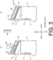
Fig. 3 (a) and (b) are schematic sectional views for describing an operation of the waterproof structure for the ventilation opening of the electronic equipment according to the embodiment of the present invention. - Hereinafter, a waterproof structure for a ventilation opening of electronic equipment according to the present invention will be described with reference to the drawings.
- In the figure, a symbol W represents a width direction (including a leftward direction W1 and a rightward direction Wr) of a housing of the electronic equipment to which the waterproof structure for the ventilation opening is applicable, a symbol H represents a height direction (including a downward direction Hl and an upward direction Hu) of the housing, and a symbol D represents a depth direction (including a frontward direction Df and a rearward direction Dr) of the housing.
- Referring to
Figs. 1 to 3 , awaterproof structure 60 according to an embodiment of the present invention is applied to a ventilation opening 11 of ahousing 10 of a gate device as electronic equipment. The gate device is arranged adjacent to an entrance/exit gate. - The gate device comprises a
circuit board 71, aCPU 72 which is mounted to thecircuit board 71 and which is for carrying out arithmetic processing of information in accordance with a software program, an information storage unit (not shown) for memorizing information including the software program also, an input/output interface for a signal representative of information including personal authentication information also, and ahousing 10 accommodating those devices. The input/output interface comprises atouch panel display 20, atouch pad 30 for contactless communication, aspeaker microphone 50, and apower supply switch 40. The gate device determines admission or denial of entrance and exit based on a security code inputted from thetouch panel display 20 or the personal authentication information inputted via thetouch pad 30, and controls a gate based on a result of determination. - The gate device is provided with cooling means because the
CPU 72 or the like generates heat following an operation. The cooling means naturally circulates air without using a fan. In order to discharge air heated to high temperature in response to heat conduction from a heat generating portion such as theCPU 72 and, conversely, to suck outside air, thehousing 10 is provided with the ventilation opening 11. Theventilation opening 11 is formed on a top surface of thehousing 10 in a height direction H in order to perform efficient ventilation. TheCPU 72 is accommodated in thehousing 10 so that an upper part of thehousing 10 in the height direction H faces the ventilation opening 11. - The
waterproof structure 60 according to the embodiment of the present invention comprises afirst filter 61, asecond filter 62, aframe member 63, agutter portion 64, and atop cover 65. - The
first filter 61 is fitted to the ventilation opening 11 of thehousing 10 to be inclined in a depth direction D of thehousing 10. Thefirst filter 61 comprises a hydromesh layer having a hydrophobic or a water-repellent property and breathability. - The
second filter 62 is mounted to thefirst filter 61 to be stacked thereon. Thesecond filter 62 comprises a foam layer having water absorbability and breathability. - As a comparative example, for instance, a hydrophobic porous material layer (waterproof moisture-permeable film) such as Gore-Tex (registered trademark), is a material preventing intrusion of water and allowing passage of inside air but is not always sufficient in breathability although waterproofness is excellent.
- In comparison, the hydromesh layer used as the
first filter 61 in the present invention is excellent in both waterproofness and breathability. However, water may possibly pass through when high water pressure is applied. On the other hand, the hydromesh layer has a performance of retaining moisture under surface tension. Therefore, in the present invention, the moisture retained on a surface of thefirst filter 61 under surface tension is slipped down to be discharged by arranging thefirst filter 61 with a slope. - It is noted that the hydromesh layer forming the
first filter 61 is, for example, meshed polyester fiber and may also be called a high-density mesh cloth. - Furthermore, the
second filter 62 comprising the foam layer is stacked as an upper layer on the hydromesh layer which may allow passage of water under high water pressure. Thus, water pressure is sufficiently reduced before the moisture reaches thefirst filter 61. In addition, as a side effect, the foam layer also prevents intrusion of dust. - The foam layer forming the
second filter 62 is, for example, urethane foam and has an open-cell foam structure in which air bubbles are interconnected. The foam layer allows a gas or a liquid to pass therethrough while meandering. - Therefore, the
waterproof structure 60 according to the embodiment of the present invention simultaneously achieves excellent breathability of exhausting heat inside the housing by natural convection and excellent waterproofness of causing the incoming moisture to be reduced in pressure, to be repelled, to flow down, and to be discharged. - The
frame member 63 is fitted to theventilation opening 11 of thehousing 10 and supports thefirst filter 61 so that the first filter is inclined in the depth direction D of thehousing 10. - The
gutter portion 64 extends below a downslope edge of thefirst filter 61 in parallel to the downslope edge. Thegutter portion 64 receives the moisture flowing down from the surface of thefirst filter 61 and discharges the moisture in an extending direction (width direction W). Theframe member 63 integrally has thegutter portion 64. - The
gutter portion 64 extends below the downslope edge of thefirst filter 61 along the downslope edge, i.e., extends in the width direction W of thehousing 10. Thegutter portion 64 receives the moisture flowing down from the surface of thefirst filter 61 and discharges the moisture in the extending direction (width direction W). In particular, in this embodiment, a bottom surface of thegutter portion 64 is inclined downward towards opposite ends from a center in the extending direction (width direction W) as apeak 64p. With the above-mentioned structure, the moisture is discharged from left and right side portions at a rear part of the housing so that the moisture is not retained on a rear surface of the housing. Accordingly, the housing of the electronic equipment can be fixed to a wall surface. - The
top cover 65 is fitted to thehousing 10 to cover thefirst filter 61 and thesecond filter 62. Thetop cover 65 has a mesh-like or a grid-like shape having a plurality of holes formed at least on an upper surface thereof. By providing thetop cover 65, thefirst filter 61 and thesecond filter 62 are prevented from sticking of a foreign substance or from being tampered. - Next, description will be made of an operation of the waterproof structure for the ventilating opening of the electronic equipment according to the embodiment of the present invention.
- As shown in
Fig. 3 (a) , when the moisture WD falls down onto the top surface of thehousing 10, the moisture WD is diffused inside the foam layer to become smaller water drops during passage through thesecond filter 62. The moisture WD is reduced in pressure or lowered in falling velocity. - Next, as shown in
Fig. 3 (b) , the moisture WD permeating thesecond filter 62 and reduced in pressure or falling velocity reaches the surface of thefirst filter 61 comprising the hydromesh layer. At the surface of thefirst filter 61, the moisture WD is repelled under surface tension. The moisture WD in the shape of the water drops flows along the slope of thefirst filter 61 in a rearward direction Dr and a downward direction Hl of thehousing 10. Then, the moisture WD flowing down from the downslope edge of thefirst filter 61 is received by thegutter portion 64 and discharged along the extending direction of the gutter portion 64 (the width direction W of the housing 10). Thegutter portion 64 may be inclined downward in the leftward direction W1 or the rightward direction Wr of thehousing 10. - As described above, the moisture WD is prevented from intruding into the
housing 10. In addition, incoming dust or foreign substances are also prevented by the second filter comprising the foam layer from intruding into thehousing 10. - On the other hand, air exposed to heat conduction from the
CPU 72 or the like generating heat in thehousing 10 is discharged through thefirst filter 61 and thesecond filter 62 to the outside of thehousing 10. Thus, heat release is achieved. - An object to which the waterproof structure for the ventilation opening of the electronic equipment according to the present invention is applicable is not limited to the gate device described above. For example, the waterproof structure according to the present invention is applicable to various types of electronic equipment, such as an oil feeding device in a self-service oil station system, which requires the ventilation opening of the housing to have breathability and to have a waterproof measure or a dustproof measure.
- The present invention is based upon and claims the benefit of priority from Japanese patent application No.
2018-002378, filed on January 11, 2018 -
- 10
- housing
- 11
- ventilation opening
- 20
- touch panel display
- 30
- touch pad
- 40
- power supply switch
- 50
- speaker microphone
- 60
- waterproof structure
- 61
- first filter
- 62
- second filter
- 63
- frame member
- 64
- gutter portion
- 64p
- peak
- 65
- top cover
- 71
- circuit board
- 72
- CPU (Central Processing Unit)
Claims (10)
- A waterproof structure provided at a ventilation opening formed on a top surface of a housing of electronic equipment, the water proof structure comprising:a first filter mounted to the ventilation opening to be inclined in a depth direction or a width direction of the housing;the first filter comprising a hydromesh layer having a hydrophobic or a water-repellent property and breathability.
- The waterproof structure for the ventilation opening of the electronic equipment according to claim 1, further comprising:a second filter mounted to the first filter to be stacked thereon,the second filter comprising a foam layer having water absorbability and breathability.
- The waterproof structure for the ventilation opening of the electronic equipment according to claim 2, further comprising:a top cover mounted to the housing to cover the first filter and the second filter,the top cover having a mesh-like or a grid-like shape with a plurality of holes formed at least on an upper surface thereof.
- The waterproof structure for the ventilation opening of the electronic equipment according to any one of claims 1 to 3, further comprising a frame member mounted to the ventilation opening to support the first filter so that the first filter is inclined in the depth direction or the width direction of the housing.
- The waterproof structure for the ventilation opening of the electronic equipment according to any one of claims 1 to 3, further comprising a gutter portion extending below a downslope edge of the first filter in parallel to the downslope edge,
the gutter portion being configured to receive moisture flowing down from a surface of the first filter and to discharge the moisture in an extending direction of the gutter portion. - The waterproof structure for the ventilation opening of the electronic equipment according to claim 4, further comprising a gutter portion formed below a downslope edge of the first filter along the downslope edge,
the gutter portion being configured to receive moisture flowing down from a surface of the first filter and to discharge the moisture in an extending direction of the gutter portion,
the frame member being integral with the gutter portion. - The waterproof structure for the ventilation opening of the electronic equipment according to claim 5 or 6, wherein:the first filter is inclined downward towards a rear part of the housing in the depth direction,the gutter portion being inclined downward towards opposite ends thereof with a center in the extending direction as a peak.
- A housing of electronic equipment, comprising the waterproof structure for the ventilation opening of the electronic equipment according to any one of claims 1 to 7.
- An electronic equipment having the housing according to claim 8.
- The electronic equipment according to claim 9, further comprising:at least one electronic component which generates heat following an operation of the electronic equipment,the electronic component being accommodated in the housing so that an upper part of the electronic component faces the ventilation opening.
Applications Claiming Priority (2)
| Application Number | Priority Date | Filing Date | Title |
|---|---|---|---|
| JP2018002378A JP6573336B2 (en) | 2018-01-11 | 2018-01-11 | Waterproof structure, casing and electronic device for ventilation opening of electronic device |
| PCT/JP2018/046476 WO2019138798A1 (en) | 2018-01-11 | 2018-12-18 | Waterproof structure for vent hole in electronic equipment, housing, and electronic equipment |
Publications (3)
| Publication Number | Publication Date |
|---|---|
| EP3740051A1 true EP3740051A1 (en) | 2020-11-18 |
| EP3740051A4 EP3740051A4 (en) | 2021-03-10 |
| EP3740051B1 EP3740051B1 (en) | 2023-04-26 |
Family
ID=67219003
Family Applications (1)
| Application Number | Title | Priority Date | Filing Date |
|---|---|---|---|
| EP18900347.8A Active EP3740051B1 (en) | 2018-01-11 | 2018-12-18 | Waterproof structure for vent hole in electronic equipment, housing, and electronic equipment |
Country Status (4)
| Country | Link |
|---|---|
| US (1) | US20200344904A1 (en) |
| EP (1) | EP3740051B1 (en) |
| JP (1) | JP6573336B2 (en) |
| WO (1) | WO2019138798A1 (en) |
Families Citing this family (2)
| Publication number | Priority date | Publication date | Assignee | Title |
|---|---|---|---|---|
| JP7652826B2 (en) * | 2023-03-27 | 2025-03-27 | 京セラ株式会社 | Electronics |
| US20250151225A1 (en) * | 2023-11-02 | 2025-05-08 | Channell Commercial Corporation | Vented pedestal housing |
Family Cites Families (15)
| Publication number | Priority date | Publication date | Assignee | Title |
|---|---|---|---|---|
| JPS5153038U (en) * | 1974-10-21 | 1976-04-22 | ||
| JPH0640350U (en) * | 1992-11-05 | 1994-05-27 | 三菱重工業株式会社 | Air cleaner |
| JPH0832248A (en) * | 1994-07-20 | 1996-02-02 | Fujitsu General Ltd | Filter mounting device |
| JP3704958B2 (en) | 1998-07-17 | 2005-10-12 | 日新電機株式会社 | Outdoor switchboard |
| JP4073764B2 (en) * | 2002-11-20 | 2008-04-09 | 東海興業株式会社 | Waterproof case body and waterproof case assembly |
| JP2004356524A (en) * | 2003-05-30 | 2004-12-16 | Keihin Corp | Electronic circuit board storage case |
| JP2006005162A (en) * | 2004-06-17 | 2006-01-05 | Denso Corp | Electronic device waterproof case |
| JP4702829B2 (en) | 2005-02-23 | 2011-06-15 | 日東電工株式会社 | Vent filter and casing provided with the same |
| EP2077145A1 (en) * | 2008-01-07 | 2009-07-08 | Nokia Siemens Networks Oy | Method, module and computer program product for monitoring a particle filter device |
| JP2010258263A (en) * | 2009-04-27 | 2010-11-11 | Funai Electric Co Ltd | Heat dissipation mechanism of electronic apparatus |
| JP6105887B2 (en) * | 2012-09-28 | 2017-03-29 | 日立オートモティブシステムズ株式会社 | Electronic control unit |
| JP2014209639A (en) * | 2014-06-12 | 2014-11-06 | 日立オートモティブシステムズ株式会社 | Electronic control device |
| JP2016158557A (en) * | 2015-03-02 | 2016-09-05 | セイコーエプソン株式会社 | Container, biological substance purification cartridge, and assembly kit for biological substance purification cartridge |
| JP6555117B2 (en) * | 2015-12-22 | 2019-08-07 | 株式会社デンソー | Electronic equipment |
| JP6735617B2 (en) | 2016-06-30 | 2020-08-05 | 株式会社エース電研 | Paper sheet collection and transport system Transport auxiliary body relay device |
-
2018
- 2018-01-11 JP JP2018002378A patent/JP6573336B2/en active Active
- 2018-12-18 WO PCT/JP2018/046476 patent/WO2019138798A1/en not_active Ceased
- 2018-12-18 EP EP18900347.8A patent/EP3740051B1/en active Active
- 2018-12-18 US US16/960,732 patent/US20200344904A1/en not_active Abandoned
Also Published As
| Publication number | Publication date |
|---|---|
| EP3740051A4 (en) | 2021-03-10 |
| JP2019121752A (en) | 2019-07-22 |
| JP6573336B2 (en) | 2019-09-11 |
| US20200344904A1 (en) | 2020-10-29 |
| EP3740051B1 (en) | 2023-04-26 |
| WO2019138798A1 (en) | 2019-07-18 |
Similar Documents
| Publication | Publication Date | Title |
|---|---|---|
| US7033267B2 (en) | Rack enclosure | |
| US20090231807A1 (en) | Waterproof Ventilated Display Enclosure | |
| US7604535B2 (en) | Assembly for extracting heat from a housing for electronic equipment | |
| US7872864B2 (en) | Dual chamber sealed portable computer | |
| KR101232761B1 (en) | The distributing board comprising porous water proofing member | |
| US20200344904A1 (en) | Waterproof structure for ventilation opening in electronic equipment, housing, and electronic equipment | |
| US6951513B1 (en) | Enclosure for the storage and operation of electronic components having increased airflow characteristics | |
| JP5494655B2 (en) | Electronic equipment, electronic equipment cooling structure, and electronic equipment cooling structure | |
| TW200820869A (en) | Electronic apparatus with water blocking and draining structure and manufacturing method thereof | |
| JP7111910B2 (en) | Imaging device | |
| EP3195082A1 (en) | Reduction of intake resistance for air flow enhancement | |
| US5915466A (en) | Heat dissipating structure for an electrical assembly | |
| JP5130960B2 (en) | Rack for mounting electronic equipment and cooling mechanism thereof | |
| CN113455113B (en) | Device and method for preventing water ingress in electronic components | |
| JP4919512B2 (en) | Air conditioning system for computer room and fan rack thereof | |
| JP4193676B2 (en) | Waterproof ventilation structure for electronic equipment | |
| JPH10198460A (en) | Dustproof system for electronic enclosure | |
| JP2010258263A (en) | Heat dissipation mechanism of electronic apparatus | |
| CN207820394U (en) | Electronic equipment | |
| JP4241454B2 (en) | Oil-proof structure of electronic equipment | |
| CN217133642U (en) | Case and electronic equipment | |
| JP2011135013A (en) | Electronic apparatus housing | |
| JP2015166659A (en) | Ventilation device for double floor | |
| RU2746065C1 (en) | Multi-service transportation platform casing | |
| JP2008159925A (en) | Electronics |
Legal Events
| Date | Code | Title | Description |
|---|---|---|---|
| STAA | Information on the status of an ep patent application or granted ep patent |
Free format text: STATUS: THE INTERNATIONAL PUBLICATION HAS BEEN MADE |
|
| PUAI | Public reference made under article 153(3) epc to a published international application that has entered the european phase |
Free format text: ORIGINAL CODE: 0009012 |
|
| STAA | Information on the status of an ep patent application or granted ep patent |
Free format text: STATUS: REQUEST FOR EXAMINATION WAS MADE |
|
| 17P | Request for examination filed |
Effective date: 20200811 |
|
| AK | Designated contracting states |
Kind code of ref document: A1 Designated state(s): AL AT BE BG CH CY CZ DE DK EE ES FI FR GB GR HR HU IE IS IT LI LT LU LV MC MK MT NL NO PL PT RO RS SE SI SK SM TR |
|
| AX | Request for extension of the european patent |
Extension state: BA ME |
|
| A4 | Supplementary search report drawn up and despatched |
Effective date: 20210208 |
|
| RIC1 | Information provided on ipc code assigned before grant |
Ipc: B01D 46/00 20060101ALI20210202BHEP Ipc: H05K 7/20 20060101ALI20210202BHEP Ipc: H05K 5/02 20060101AFI20210202BHEP Ipc: H05K 5/03 20060101ALI20210202BHEP |
|
| DAV | Request for validation of the european patent (deleted) | ||
| DAX | Request for extension of the european patent (deleted) | ||
| GRAP | Despatch of communication of intention to grant a patent |
Free format text: ORIGINAL CODE: EPIDOSNIGR1 |
|
| STAA | Information on the status of an ep patent application or granted ep patent |
Free format text: STATUS: GRANT OF PATENT IS INTENDED |
|
| INTG | Intention to grant announced |
Effective date: 20221115 |
|
| GRAS | Grant fee paid |
Free format text: ORIGINAL CODE: EPIDOSNIGR3 |
|
| GRAA | (expected) grant |
Free format text: ORIGINAL CODE: 0009210 |
|
| STAA | Information on the status of an ep patent application or granted ep patent |
Free format text: STATUS: THE PATENT HAS BEEN GRANTED |
|
| AK | Designated contracting states |
Kind code of ref document: B1 Designated state(s): AL AT BE BG CH CY CZ DE DK EE ES FI FR GB GR HR HU IE IS IT LI LT LU LV MC MK MT NL NO PL PT RO RS SE SI SK SM TR |
|
| REG | Reference to a national code |
Ref country code: GB Ref legal event code: FG4D |
|
| REG | Reference to a national code |
Ref country code: CH Ref legal event code: EP |
|
| REG | Reference to a national code |
Ref country code: DE Ref legal event code: R096 Ref document number: 602018049047 Country of ref document: DE |
|
| REG | Reference to a national code |
Ref country code: AT Ref legal event code: REF Ref document number: 1563791 Country of ref document: AT Kind code of ref document: T Effective date: 20230515 |
|
| REG | Reference to a national code |
Ref country code: IE Ref legal event code: FG4D |
|
| REG | Reference to a national code |
Ref country code: LT Ref legal event code: MG9D |
|
| REG | Reference to a national code |
Ref country code: NL Ref legal event code: MP Effective date: 20230426 |
|
| REG | Reference to a national code |
Ref country code: AT Ref legal event code: MK05 Ref document number: 1563791 Country of ref document: AT Kind code of ref document: T Effective date: 20230426 |
|
| PG25 | Lapsed in a contracting state [announced via postgrant information from national office to epo] |
Ref country code: NL Free format text: LAPSE BECAUSE OF FAILURE TO SUBMIT A TRANSLATION OF THE DESCRIPTION OR TO PAY THE FEE WITHIN THE PRESCRIBED TIME-LIMIT Effective date: 20230426 |
|
| PG25 | Lapsed in a contracting state [announced via postgrant information from national office to epo] |
Ref country code: SE Free format text: LAPSE BECAUSE OF FAILURE TO SUBMIT A TRANSLATION OF THE DESCRIPTION OR TO PAY THE FEE WITHIN THE PRESCRIBED TIME-LIMIT Effective date: 20230426 Ref country code: PT Free format text: LAPSE BECAUSE OF FAILURE TO SUBMIT A TRANSLATION OF THE DESCRIPTION OR TO PAY THE FEE WITHIN THE PRESCRIBED TIME-LIMIT Effective date: 20230828 Ref country code: NO Free format text: LAPSE BECAUSE OF FAILURE TO SUBMIT A TRANSLATION OF THE DESCRIPTION OR TO PAY THE FEE WITHIN THE PRESCRIBED TIME-LIMIT Effective date: 20230726 Ref country code: ES Free format text: LAPSE BECAUSE OF FAILURE TO SUBMIT A TRANSLATION OF THE DESCRIPTION OR TO PAY THE FEE WITHIN THE PRESCRIBED TIME-LIMIT Effective date: 20230426 Ref country code: AT Free format text: LAPSE BECAUSE OF FAILURE TO SUBMIT A TRANSLATION OF THE DESCRIPTION OR TO PAY THE FEE WITHIN THE PRESCRIBED TIME-LIMIT Effective date: 20230426 |
|
| PG25 | Lapsed in a contracting state [announced via postgrant information from national office to epo] |
Ref country code: RS Free format text: LAPSE BECAUSE OF FAILURE TO SUBMIT A TRANSLATION OF THE DESCRIPTION OR TO PAY THE FEE WITHIN THE PRESCRIBED TIME-LIMIT Effective date: 20230426 Ref country code: PL Free format text: LAPSE BECAUSE OF FAILURE TO SUBMIT A TRANSLATION OF THE DESCRIPTION OR TO PAY THE FEE WITHIN THE PRESCRIBED TIME-LIMIT Effective date: 20230426 Ref country code: LV Free format text: LAPSE BECAUSE OF FAILURE TO SUBMIT A TRANSLATION OF THE DESCRIPTION OR TO PAY THE FEE WITHIN THE PRESCRIBED TIME-LIMIT Effective date: 20230426 Ref country code: LT Free format text: LAPSE BECAUSE OF FAILURE TO SUBMIT A TRANSLATION OF THE DESCRIPTION OR TO PAY THE FEE WITHIN THE PRESCRIBED TIME-LIMIT Effective date: 20230426 Ref country code: IS Free format text: LAPSE BECAUSE OF FAILURE TO SUBMIT A TRANSLATION OF THE DESCRIPTION OR TO PAY THE FEE WITHIN THE PRESCRIBED TIME-LIMIT Effective date: 20230826 Ref country code: HR Free format text: LAPSE BECAUSE OF FAILURE TO SUBMIT A TRANSLATION OF THE DESCRIPTION OR TO PAY THE FEE WITHIN THE PRESCRIBED TIME-LIMIT Effective date: 20230426 Ref country code: GR Free format text: LAPSE BECAUSE OF FAILURE TO SUBMIT A TRANSLATION OF THE DESCRIPTION OR TO PAY THE FEE WITHIN THE PRESCRIBED TIME-LIMIT Effective date: 20230727 |
|
| PG25 | Lapsed in a contracting state [announced via postgrant information from national office to epo] |
Ref country code: FI Free format text: LAPSE BECAUSE OF FAILURE TO SUBMIT A TRANSLATION OF THE DESCRIPTION OR TO PAY THE FEE WITHIN THE PRESCRIBED TIME-LIMIT Effective date: 20230426 |
|
| PG25 | Lapsed in a contracting state [announced via postgrant information from national office to epo] |
Ref country code: SK Free format text: LAPSE BECAUSE OF FAILURE TO SUBMIT A TRANSLATION OF THE DESCRIPTION OR TO PAY THE FEE WITHIN THE PRESCRIBED TIME-LIMIT Effective date: 20230426 |
|
| REG | Reference to a national code |
Ref country code: DE Ref legal event code: R097 Ref document number: 602018049047 Country of ref document: DE |
|
| PG25 | Lapsed in a contracting state [announced via postgrant information from national office to epo] |
Ref country code: SM Free format text: LAPSE BECAUSE OF FAILURE TO SUBMIT A TRANSLATION OF THE DESCRIPTION OR TO PAY THE FEE WITHIN THE PRESCRIBED TIME-LIMIT Effective date: 20230426 Ref country code: SK Free format text: LAPSE BECAUSE OF FAILURE TO SUBMIT A TRANSLATION OF THE DESCRIPTION OR TO PAY THE FEE WITHIN THE PRESCRIBED TIME-LIMIT Effective date: 20230426 Ref country code: RO Free format text: LAPSE BECAUSE OF FAILURE TO SUBMIT A TRANSLATION OF THE DESCRIPTION OR TO PAY THE FEE WITHIN THE PRESCRIBED TIME-LIMIT Effective date: 20230426 Ref country code: EE Free format text: LAPSE BECAUSE OF FAILURE TO SUBMIT A TRANSLATION OF THE DESCRIPTION OR TO PAY THE FEE WITHIN THE PRESCRIBED TIME-LIMIT Effective date: 20230426 Ref country code: DK Free format text: LAPSE BECAUSE OF FAILURE TO SUBMIT A TRANSLATION OF THE DESCRIPTION OR TO PAY THE FEE WITHIN THE PRESCRIBED TIME-LIMIT Effective date: 20230426 Ref country code: CZ Free format text: LAPSE BECAUSE OF FAILURE TO SUBMIT A TRANSLATION OF THE DESCRIPTION OR TO PAY THE FEE WITHIN THE PRESCRIBED TIME-LIMIT Effective date: 20230426 |
|
| PLBE | No opposition filed within time limit |
Free format text: ORIGINAL CODE: 0009261 |
|
| STAA | Information on the status of an ep patent application or granted ep patent |
Free format text: STATUS: NO OPPOSITION FILED WITHIN TIME LIMIT |
|
| 26N | No opposition filed |
Effective date: 20240129 |
|
| PG25 | Lapsed in a contracting state [announced via postgrant information from national office to epo] |
Ref country code: SI Free format text: LAPSE BECAUSE OF FAILURE TO SUBMIT A TRANSLATION OF THE DESCRIPTION OR TO PAY THE FEE WITHIN THE PRESCRIBED TIME-LIMIT Effective date: 20230426 |
|
| PG25 | Lapsed in a contracting state [announced via postgrant information from national office to epo] |
Ref country code: SI Free format text: LAPSE BECAUSE OF FAILURE TO SUBMIT A TRANSLATION OF THE DESCRIPTION OR TO PAY THE FEE WITHIN THE PRESCRIBED TIME-LIMIT Effective date: 20230426 Ref country code: IT Free format text: LAPSE BECAUSE OF FAILURE TO SUBMIT A TRANSLATION OF THE DESCRIPTION OR TO PAY THE FEE WITHIN THE PRESCRIBED TIME-LIMIT Effective date: 20230426 |
|
| REG | Reference to a national code |
Ref country code: CH Ref legal event code: PL |
|
| PG25 | Lapsed in a contracting state [announced via postgrant information from national office to epo] |
Ref country code: LU Free format text: LAPSE BECAUSE OF NON-PAYMENT OF DUE FEES Effective date: 20231218 |
|
| PG25 | Lapsed in a contracting state [announced via postgrant information from national office to epo] |
Ref country code: MC Free format text: LAPSE BECAUSE OF FAILURE TO SUBMIT A TRANSLATION OF THE DESCRIPTION OR TO PAY THE FEE WITHIN THE PRESCRIBED TIME-LIMIT Effective date: 20230426 |
|
| REG | Reference to a national code |
Ref country code: BE Ref legal event code: MM Effective date: 20231231 |
|
| PG25 | Lapsed in a contracting state [announced via postgrant information from national office to epo] |
Ref country code: MC Free format text: LAPSE BECAUSE OF FAILURE TO SUBMIT A TRANSLATION OF THE DESCRIPTION OR TO PAY THE FEE WITHIN THE PRESCRIBED TIME-LIMIT Effective date: 20230426 Ref country code: LU Free format text: LAPSE BECAUSE OF NON-PAYMENT OF DUE FEES Effective date: 20231218 |
|
| REG | Reference to a national code |
Ref country code: IE Ref legal event code: MM4A |
|
| PG25 | Lapsed in a contracting state [announced via postgrant information from national office to epo] |
Ref country code: IE Free format text: LAPSE BECAUSE OF NON-PAYMENT OF DUE FEES Effective date: 20231218 |
|
| PG25 | Lapsed in a contracting state [announced via postgrant information from national office to epo] |
Ref country code: BE Free format text: LAPSE BECAUSE OF NON-PAYMENT OF DUE FEES Effective date: 20231231 |
|
| PG25 | Lapsed in a contracting state [announced via postgrant information from national office to epo] |
Ref country code: CH Free format text: LAPSE BECAUSE OF NON-PAYMENT OF DUE FEES Effective date: 20231231 |
|
| PG25 | Lapsed in a contracting state [announced via postgrant information from national office to epo] |
Ref country code: IE Free format text: LAPSE BECAUSE OF NON-PAYMENT OF DUE FEES Effective date: 20231218 Ref country code: CH Free format text: LAPSE BECAUSE OF NON-PAYMENT OF DUE FEES Effective date: 20231231 Ref country code: BE Free format text: LAPSE BECAUSE OF NON-PAYMENT OF DUE FEES Effective date: 20231231 |
|
| PG25 | Lapsed in a contracting state [announced via postgrant information from national office to epo] |
Ref country code: BG Free format text: LAPSE BECAUSE OF FAILURE TO SUBMIT A TRANSLATION OF THE DESCRIPTION OR TO PAY THE FEE WITHIN THE PRESCRIBED TIME-LIMIT Effective date: 20230426 |
|
| PG25 | Lapsed in a contracting state [announced via postgrant information from national office to epo] |
Ref country code: BG Free format text: LAPSE BECAUSE OF FAILURE TO SUBMIT A TRANSLATION OF THE DESCRIPTION OR TO PAY THE FEE WITHIN THE PRESCRIBED TIME-LIMIT Effective date: 20230426 |
|
| PGFP | Annual fee paid to national office [announced via postgrant information from national office to epo] |
Ref country code: DE Payment date: 20241210 Year of fee payment: 7 |
|
| PGFP | Annual fee paid to national office [announced via postgrant information from national office to epo] |
Ref country code: GB Payment date: 20241227 Year of fee payment: 7 |
|
| PGFP | Annual fee paid to national office [announced via postgrant information from national office to epo] |
Ref country code: FR Payment date: 20241224 Year of fee payment: 7 |
|
| PG25 | Lapsed in a contracting state [announced via postgrant information from national office to epo] |
Ref country code: CY Free format text: LAPSE BECAUSE OF FAILURE TO SUBMIT A TRANSLATION OF THE DESCRIPTION OR TO PAY THE FEE WITHIN THE PRESCRIBED TIME-LIMIT; INVALID AB INITIO Effective date: 20181218 |
|
| PG25 | Lapsed in a contracting state [announced via postgrant information from national office to epo] |
Ref country code: HU Free format text: LAPSE BECAUSE OF FAILURE TO SUBMIT A TRANSLATION OF THE DESCRIPTION OR TO PAY THE FEE WITHIN THE PRESCRIBED TIME-LIMIT; INVALID AB INITIO Effective date: 20181218 |
|
| PG25 | Lapsed in a contracting state [announced via postgrant information from national office to epo] |
Ref country code: TR Free format text: LAPSE BECAUSE OF FAILURE TO SUBMIT A TRANSLATION OF THE DESCRIPTION OR TO PAY THE FEE WITHIN THE PRESCRIBED TIME-LIMIT Effective date: 20230426 |
|
| REG | Reference to a national code |
Ref country code: DE Ref legal event code: R081 Ref document number: 602018049047 Country of ref document: DE Owner name: STEERETAIL CO., LTD., KAWASAKI-SHI, JP Free format text: FORMER OWNER: NEC PLATFORMS, LTD., KAWASAKI-SHI, KANAGAWA, JP Ref country code: DE Ref legal event code: R082 Ref document number: 602018049047 Country of ref document: DE Representative=s name: 2SPL PATENTANWAELTE PARTG MBB SCHULER SCHACHT , DE |