EP3739880A1 - Verfahren, vorrichtung und computerprogrammprodukt zur codierung eines verzerrten bildrahmens - Google Patents
Verfahren, vorrichtung und computerprogrammprodukt zur codierung eines verzerrten bildrahmens Download PDFInfo
- Publication number
- EP3739880A1 EP3739880A1 EP19174349.1A EP19174349A EP3739880A1 EP 3739880 A1 EP3739880 A1 EP 3739880A1 EP 19174349 A EP19174349 A EP 19174349A EP 3739880 A1 EP3739880 A1 EP 3739880A1
- Authority
- EP
- European Patent Office
- Prior art keywords
- distorted image
- image frames
- spatial resolution
- map
- pixel block
- Prior art date
- Legal status (The legal status is an assumption and is not a legal conclusion. Google has not performed a legal analysis and makes no representation as to the accuracy of the status listed.)
- Pending
Links
Images

Classifications
-
- H—ELECTRICITY
- H04—ELECTRIC COMMUNICATION TECHNIQUE
- H04N—PICTORIAL COMMUNICATION, e.g. TELEVISION
- H04N19/00—Methods or arrangements for coding, decoding, compressing or decompressing digital video signals
- H04N19/10—Methods or arrangements for coding, decoding, compressing or decompressing digital video signals using adaptive coding
- H04N19/102—Methods or arrangements for coding, decoding, compressing or decompressing digital video signals using adaptive coding characterised by the element, parameter or selection affected or controlled by the adaptive coding
- H04N19/119—Adaptive subdivision aspects, e.g. subdivision of a picture into rectangular or non-rectangular coding blocks
-
- H—ELECTRICITY
- H04—ELECTRIC COMMUNICATION TECHNIQUE
- H04N—PICTORIAL COMMUNICATION, e.g. TELEVISION
- H04N19/00—Methods or arrangements for coding, decoding, compressing or decompressing digital video signals
- H04N19/50—Methods or arrangements for coding, decoding, compressing or decompressing digital video signals using predictive coding
- H04N19/597—Methods or arrangements for coding, decoding, compressing or decompressing digital video signals using predictive coding specially adapted for multi-view video sequence encoding
-
- H—ELECTRICITY
- H04—ELECTRIC COMMUNICATION TECHNIQUE
- H04N—PICTORIAL COMMUNICATION, e.g. TELEVISION
- H04N19/00—Methods or arrangements for coding, decoding, compressing or decompressing digital video signals
- H04N19/10—Methods or arrangements for coding, decoding, compressing or decompressing digital video signals using adaptive coding
- H04N19/134—Methods or arrangements for coding, decoding, compressing or decompressing digital video signals using adaptive coding characterised by the element, parameter or criterion affecting or controlling the adaptive coding
- H04N19/146—Data rate or code amount at the encoder output
- H04N19/147—Data rate or code amount at the encoder output according to rate distortion criteria
-
- H—ELECTRICITY
- H04—ELECTRIC COMMUNICATION TECHNIQUE
- H04N—PICTORIAL COMMUNICATION, e.g. TELEVISION
- H04N19/00—Methods or arrangements for coding, decoding, compressing or decompressing digital video signals
- H04N19/10—Methods or arrangements for coding, decoding, compressing or decompressing digital video signals using adaptive coding
- H04N19/102—Methods or arrangements for coding, decoding, compressing or decompressing digital video signals using adaptive coding characterised by the element, parameter or selection affected or controlled by the adaptive coding
- H04N19/12—Selection from among a plurality of transforms or standards, e.g. selection between discrete cosine transform [DCT] and sub-band transform or selection between H.263 and H.264
-
- H—ELECTRICITY
- H04—ELECTRIC COMMUNICATION TECHNIQUE
- H04N—PICTORIAL COMMUNICATION, e.g. TELEVISION
- H04N19/00—Methods or arrangements for coding, decoding, compressing or decompressing digital video signals
- H04N19/10—Methods or arrangements for coding, decoding, compressing or decompressing digital video signals using adaptive coding
- H04N19/134—Methods or arrangements for coding, decoding, compressing or decompressing digital video signals using adaptive coding characterised by the element, parameter or criterion affecting or controlling the adaptive coding
- H04N19/154—Measured or subjectively estimated visual quality after decoding, e.g. measurement of distortion
-
- H—ELECTRICITY
- H04—ELECTRIC COMMUNICATION TECHNIQUE
- H04N—PICTORIAL COMMUNICATION, e.g. TELEVISION
- H04N19/00—Methods or arrangements for coding, decoding, compressing or decompressing digital video signals
- H04N19/10—Methods or arrangements for coding, decoding, compressing or decompressing digital video signals using adaptive coding
- H04N19/134—Methods or arrangements for coding, decoding, compressing or decompressing digital video signals using adaptive coding characterised by the element, parameter or criterion affecting or controlling the adaptive coding
- H04N19/157—Assigned coding mode, i.e. the coding mode being predefined or preselected to be further used for selection of another element or parameter
- H04N19/16—Assigned coding mode, i.e. the coding mode being predefined or preselected to be further used for selection of another element or parameter for a given display mode, e.g. for interlaced or progressive display mode
-
- H—ELECTRICITY
- H04—ELECTRIC COMMUNICATION TECHNIQUE
- H04N—PICTORIAL COMMUNICATION, e.g. TELEVISION
- H04N19/00—Methods or arrangements for coding, decoding, compressing or decompressing digital video signals
- H04N19/10—Methods or arrangements for coding, decoding, compressing or decompressing digital video signals using adaptive coding
- H04N19/169—Methods or arrangements for coding, decoding, compressing or decompressing digital video signals using adaptive coding characterised by the coding unit, i.e. the structural portion or semantic portion of the video signal being the object or the subject of the adaptive coding
- H04N19/17—Methods or arrangements for coding, decoding, compressing or decompressing digital video signals using adaptive coding characterised by the coding unit, i.e. the structural portion or semantic portion of the video signal being the object or the subject of the adaptive coding the unit being an image region, e.g. an object
- H04N19/176—Methods or arrangements for coding, decoding, compressing or decompressing digital video signals using adaptive coding characterised by the coding unit, i.e. the structural portion or semantic portion of the video signal being the object or the subject of the adaptive coding the unit being an image region, e.g. an object the region being a block, e.g. a macroblock
-
- H—ELECTRICITY
- H04—ELECTRIC COMMUNICATION TECHNIQUE
- H04N—PICTORIAL COMMUNICATION, e.g. TELEVISION
- H04N19/00—Methods or arrangements for coding, decoding, compressing or decompressing digital video signals
- H04N19/10—Methods or arrangements for coding, decoding, compressing or decompressing digital video signals using adaptive coding
- H04N19/169—Methods or arrangements for coding, decoding, compressing or decompressing digital video signals using adaptive coding characterised by the coding unit, i.e. the structural portion or semantic portion of the video signal being the object or the subject of the adaptive coding
- H04N19/182—Methods or arrangements for coding, decoding, compressing or decompressing digital video signals using adaptive coding characterised by the coding unit, i.e. the structural portion or semantic portion of the video signal being the object or the subject of the adaptive coding the unit being a pixel
-
- H—ELECTRICITY
- H04—ELECTRIC COMMUNICATION TECHNIQUE
- H04N—PICTORIAL COMMUNICATION, e.g. TELEVISION
- H04N19/00—Methods or arrangements for coding, decoding, compressing or decompressing digital video signals
- H04N19/44—Decoders specially adapted therefor, e.g. video decoders which are asymmetric with respect to the encoder
-
- H—ELECTRICITY
- H04—ELECTRIC COMMUNICATION TECHNIQUE
- H04N—PICTORIAL COMMUNICATION, e.g. TELEVISION
- H04N19/00—Methods or arrangements for coding, decoding, compressing or decompressing digital video signals
- H04N19/70—Methods or arrangements for coding, decoding, compressing or decompressing digital video signals characterised by syntax aspects related to video coding, e.g. related to compression standards
-
- H—ELECTRICITY
- H04—ELECTRIC COMMUNICATION TECHNIQUE
- H04N—PICTORIAL COMMUNICATION, e.g. TELEVISION
- H04N19/00—Methods or arrangements for coding, decoding, compressing or decompressing digital video signals
- H04N19/85—Methods or arrangements for coding, decoding, compressing or decompressing digital video signals using pre-processing or post-processing specially adapted for video compression
-
- H—ELECTRICITY
- H04—ELECTRIC COMMUNICATION TECHNIQUE
- H04N—PICTORIAL COMMUNICATION, e.g. TELEVISION
- H04N5/00—Details of television systems
- H04N5/222—Studio circuitry; Studio devices; Studio equipment
- H04N5/262—Studio circuits, e.g. for mixing, switching-over, change of character of image, other special effects ; Cameras specially adapted for the electronic generation of special effects
- H04N5/265—Mixing
Definitions
- the present invention relates to encoding, using a block-based video encoding algorithm, distorted image frames produced via at least one image sensor.
- An important field for camera applications is monitoring of a location.
- different camera configurations are used depending on the monitored location.
- a parking lot can be monitored using one or more cameras capable of producing wide-angle videos (e.g. by panoramic stitching or using wide-angle lenses) in order to retrieve an aerial overview of the parking lot.
- wide-angle videos the size of an objects varies over the frame, which is an effect of the uneven spatial resolution over the video frames.
- a size of a vehicle moving through the monitored scene will therefore change, as the size depends on the present position in the monitored scene.
- Videos of the monitored location are typically processed using a wide range of different image-processing algorithms. For instance, the videos are encoded, in order to reduce bandwidth requirements and file sizes associated with the encoded videos.
- a challenge for video encoding is to provide an adequate visual quality of moving objects in the encoded video due to uneven spatial resolution in the video frame.
- a method for encoding, using a block-based video encoding algorithm, distorted image frames produced via at least one image sensor comprises: determining a spatial resolution distribution for the distorted image frames; determining a map of maximum pixel block sizes corresponding to the distorted image frames, wherein the map of maximum pixel block sizes is determined based on the spatial resolution distribution such that for a first portion of the distorted image frames having a first spatial resolution, the maximum pixel block size corresponding to the first portion is set to a first value, and for a second portion of the distorted image frames having a second spatial resolution being lower than the first spatial resolution, the maximum pixel block size corresponding to the second portion is set to a second value being lower than the first value; and encoding, using the block-based video encoding algorithm, the distorted image frames, wherein the map of maximum pixel block sizes is used for defining maximum block sizes for encoding blocks of the block-based video encoding algorithm.
- distorted image frame should be construed as an image frame which has a distorted perspective.
- straight lines in the scene are typically curved to some degree.
- a perfectly rectilinear image frame has perfectly straight lines corresponding to straight lines in a depicted scene.
- two types of distortion sources are discussed: physical distortion sources and digital distortion sources.
- physical distortion sources are wide-angle lenses, including fish-eye lenses (e.g. f-theta lenses), optical domes and imperfectly rectilinear lenses. Imperfections in a lens may be caused by manufacturing imprecisions.
- Non-limiting examples of digital distortion sources are image stitching algorithms, for example for producing a panoramic image from a plurality of images.
- the distortion pattern can be irregular or regular (such as radial distortions).
- the distortion pattern of a captured image may be the result from one or a combination of distortion sources.
- spatial resolution should be understood as a spatial resolution for an image frame.
- a distorted image frame acquired through e.g. a wide-angle lens or stitched from multiple image frames
- different portions of the image have different spatial resolution.
- equally sized portions of the image frame cover differently sized angles of the camera's field of view (FOV).
- the spatial resolution may be specified on a pixel level for an image frame, or can be determined on a pixel sub-group level, e.g. on a macroblock level.
- Spatial resolution may be expressed as number of pixels per FOV angle, or as amount of FOV angle per pixel. The skilled person is familiar with how to interchange between these expressions depending on application.
- a spatial resolution distribution may be represented by, e.g., a table indicating the spatial resolution distribution for pixels or pixel sub-groups, e.g. for macroblocks.
- block-based video encoding algorithm should be construed as an algorithm for encoding video in which a set of neighboring pixels in an image frame are processed as an encoding block.
- the size of the encoding block may vary in between individual frames in a video stream for corresponding portions of pixels of the individual frames of the video stream.
- the size of different pixel blocks in a frame may vary.
- a large size of the encoding blocks results in a lower computational cost associated with encoding, which is why the block-based video encoding algorithm typically is programmed to use as large size as possible of the encoding blocks.
- a large size of encoding blocks also leads to a reduced visual quality of the encoded video.
- the block-based video encoding algorithm is therefore programmed to balance the size of the encoding blocks and the visual quality of the encoded video.
- encoding block should be construed as the basic processing unit of the block-based video encoding algorithm.
- the encoding block may be a coding unit (CU).
- the maximum block sizes for encoding blocks of the block-based video encoding algorithm are based on the spatial distribution for the distorted image frames, and thereby an improved visual quality of the encoded video is allowed. Since the spatial resolutions of the first and second portions are different, basing the maximum block sizes for encoding blocks of the block-based encoding algorithm on the spatial resolution, a more homogenous, and therefore improved, visual quality of the encoded video is allowed. Specifically, by setting a lower maximum pixel block size for areas in the distorted image with a lower spatial resolution, details in these areas of the distorted image frame may be better preserved in the encoded image frame.
- the block-based video encoding algorithm may be h.265 or AV1, and wherein the map of maximum pixel block sizes may be used for defining maximum sizes of coding units of the block-based video encoding algorithm.
- An advantage associated with the block-based video encoding algorithm being h.265 is that the maximum sizes of coding units of the block-based video encoding algorithm may be set by setting a size of a coding tree unit, CTU, of the block-based video encoding algorithm.
- An advantage associated with the block-based video encoding algorithm being AV1 is that the maximum sizes of coding units of the block-based video encoding algorithm may be set by setting a size of a superblock of the block-based video encoding algorithm.
- the present embodiment can thus advantageously be employed by standard encoders/decoders.
- the method may further comprise: determining a map of minimum pixel block sizes corresponding to the distorted image frames, wherein the map of minimum pixel block sizes comprises areas having different minimum pixel block sizes, and wherein the map of minimum pixel block sizes is determined based on the spatial resolution distribution such that for the first portion of the distorted image frames having the first spatial resolution, the minimum pixel block size corresponding to the first portion is set to a third value being lower than the first value, and for the second portion of the distorted image frames having the second spatial resolution, the minimum pixel block size corresponding to the second portion is set to a fourth value being lower than the second value and the third value; and wherein, in the step of encoding the distorted image frames, the map of minimum pixel block sizes may be used for defining minimum block sizes for encoding blocks of the block-based video encoding algorithm.
- An advantage associated with using the map of minimum pixel block sizes for defining minimum block sizes for encoding blocks of the block-based video encoding algorithm according to the present embodiment is that a computational cost, file size and/or a bandwidth associated with video encoding may be reduced and still allowing a homogenous, and therefore improved, visual quality of the encoded video.
- the encoder can advantageously choose to use a higher compression ratio for the first portion compared to the second portion.
- the block-based video encoding algorithm may be h.265, and wherein the map of minimum pixel block sizes may be used for defining the minimum sizes of prediction units, PU, and/or transform units, TU, of the block-based video encoding algorithm.
- the present embodiment allows for a low complexity implementation of the minimum block sizes using a standard h.265 encoder/decoder.
- the distorted image frames may be produced by capturing by one image sensor through a wide-angle lens, and wherein the spatial resolution distribution may be determined based on a lens polynomial of the wide-angle lens.
- lens polynomial should be construed as a lens-specific polynomial describing that represents the lens refraction for a lens or for an optical dome.
- the lens polynomial may be acquired by performing measurements, e.g. using an off-axis modular transfer function (MTF) measurement method, on the lens or on the optical dome.
- MTF modular transfer function
- a lens or optical dome manufacturer can typically provide the lens polynomial, or a table representing the distortion, for different types of lenses or optical domes in their assortment.
- An advantage associated with capturing the distorted image frames by one image sensor through a wide-angle lens is that a wide panoramic of a scene using one image sensor may be allowed and still allow for a homogenous, and therefore improved, visual quality of the encoded video. Consequently, a wide panoramic view with an improved visual quality may be achieved without a need for stitching together image frames captured by separate cameras.
- An advantage associated with the spatial resolution distribution being determined based on a lens polynomial of the wide-angle lens is that an easy and less complex determination of the spatial resolution distribution may be allowed.
- the wide-angle lens may be a fisheye lens.
- An advantage associated with the wide-angle lens being a fisheye lens is that a wide panoramic or hemispherical image frames of a scene using one image sensor may be allowed and still allow for a homogenous, and therefore improved, visual quality of the encoded video. Consequently, a wide panoramic or hemispherical view with an improved visual quality may be achieved without a need for stitching together image frames captured by separate cameras.
- the distorted image frames may be produced by capturing by one image sensor through an optical dome, and wherein the spatial resolution distribution may be determined based on a lens polynomial of the optical dome.
- An advantage associated with distorted image frames being produced by capturing by one image sensor through an optical dome is that a wide panoramic or hemispherical image frames of a scene using one image sensor may be allowed and still allow for a homogenous, and therefore improved, visual quality of the encoded video. Consequently, a wide panoramic or hemispherical view with an improved visual quality may be achieved without a need for stitching together image frames captured by separate cameras.
- An advantage associated with the spatial resolution distribution being determined based on a lens polynomial of the optical dome is that an easy and less complex determination of the spatial resolution distribution may be allowed.
- the first and second areas of the map of maximum pixel sizes may form elliptical patterns radially extending from a reference position of the motion detection sensitivity map; and wherein a radial distance between the reference position and the first area may be smaller than a radial distance between the reference position and the second area.
- An advantage associated with the first and second areas of the map of maximum pixel sizes forming elliptical patterns radially extending from a reference position of the motion detection sensitivity map is that an easy and less complex determination of the map of maximum pixel sizes may be allowed.
- Each distorted image frame may be produced by a stitching, based on a projection algorithm, of a plurality of primary image frames captured by one or more image sensors.
- projection algorithm should be construed as an algorithm that describes how multiple primary image frames are stitched/combined to form a stitched image frame.
- the projection algorithm may be designed with different purposes, e.g. for providing a smooth transition between the primary image frames or for minimizing distortions in the resulting image frame.
- An advantage of producing each distorted image frame by a stitching, based on a projection algorithm, of a plurality of primary image frames captured by one or more image sensors is that a stitched image frame having a larger number of pixels may be allowed.
- a further advantage of producing each distorted image frame by a stitching, based on a projection algorithm, of a plurality of primary image frames captured by one or more image sensors is that panoramic image frames without complex optical components, e.g. fisheye lenses or optical domes, may be allowed.
- the spatial resolution distribution may be determined based on the projection algorithm.
- An associated advantage is that the minimum and/or maximum block sizes for encoding blocks may be defined such that the visual quality of the stitched image frames or panoramic image frames is improved.
- a further associated advantage is that it may be an easy and less complex way to determine the spatial resolution distribution, e.g. by using an inverse of the projection algorithm.
- the computer program product comprises a computer-readable medium having computer code instructions stored thereon adapted to carry out the present method when executed by a device having processing capability.
- the computer-readable medium may be a non-transitory computer-readable medium.
- an encoder for encoding, using a block-based video encoding algorithm, distorted image frames produced via at least one image sensor comprises: a spatial resolution distribution component adapted to determine a spatial resolution distribution for the distorted image frames; a maximum pixel block sizes map component adapted to determine a map of maximum pixel block sizes corresponding to the distorted image frames, wherein the map of maximum pixel block sizes is determined based on the spatial resolution distribution such that for a first portion of the distorted image frames having a first spatial resolution, the maximum pixel block size corresponding to the first portion is set to a first value, and for a second portion for the distorted image frames having a second spatial resolution being lower than the first spatial resolution, the maximum pixel block size corresponding to the second portion is set to a second value being lower than the first value; and a video encoding component adapted to encode, using the block-based video encoding algorithm, the distorted image frames, wherein the map of maximum pixel block sizes is used by the block-
- the encoder may further comprise: a minimum pixel block sizes map component adapted to determine a map of minimum pixel block sizes corresponding to the distorted image frames, the map of minimum pixel block sizes comprising areas having different minimum pixel block sizes, and wherein the map of minimum pixel block sizes is determined based on the spatial resolution distribution such that for the first portion of the distorted image frames having the first spatial resolution, the minimum pixel block size corresponding to the first portion is set to a third value being lower than the first value, and for the second portion of the distorted image frames having the second spatial resolution, the minimum pixel block size corresponding to the second portion is set to a fourth value being lower than the second value and the third value; and wherein the map of minimum pixel block sizes may be used by the block-based video encoding algorithm for defining minimum block sizes for encoding blocks of the block-based video encoding algorithm.
- a camera comprises the encoder according to the third aspect.
- the camera may further comprise a wide-angle lens through which images are captured by one image sensor of the camera.
- the camera may further comprise a plurality of image sensors, and wherein the encoder further comprises a stitching component adapted to stitch image frames from a plurality of primary images captured by the plurality of image sensors.
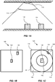
- Figure 1A illustrates a side view of a scene monitored from above by a camera 110.
- the scene comprises a first box 122, and a second box 124 having similar sizes.
- the camera 110 comprises at least one image sensor arranged to produce distorted image frames of the scene.
- the camera 110 in Fig. 1A may be the camera 210 described in relation to Fig. 2B or the camera 410 described in relation to Fig. 2C .
- An example of a distorted image frame 140 of the scene illustrated in Fig. 1A will be described in relation to Fig. 1C .
- the camera 110 has a wide field of view 112.
- the wide field of view 112 may be up to 180°.
- An associated solid angle of the wide field of view 112 may be up to 2 ⁇ sr.
- Figure 1B illustrates a rectilinear image frame 130 of a top view of the scene monitored in Fig. 1A .
- each of the boxes 122, 124 have similar sizes when seen from above in the rectilinear image frame 130.
- a spatial resolution in the rectilinear image frame 130 in Fig. 1B is substantially constant over the rectilinear image frame 130.
- Figure 1C illustrates a distorted image frame 140 of the top view in Fig. 1B .
- the distorted image frame 140 may be produced by capturing by one image sensor through a wide-angle lens.
- the distorted image frame 140 may be produced by capturing by one image sensor through an optical dome.
- the distorted image frame 140 may be produced by stitching, based on a projection algorithm, a plurality of primary images, as will be described in relation to Fig. 2C .
- the apparent sizes of the boxes 122, 124 varies depending on the position of each box 122, 124 in the distorted image frame 140.
- a spatial resolution in the distorted image frame 140 varies over the distorted image frame 140.
- the spatial distribution may be determined based on the distorted image frame 140 and the rectilinear image frame 130.
- the spatial distribution may be determined based on the wide-angle lens of the camera 110.
- the distorted image frame 140 may be produced by capturing by one image sensor through a wide-angle lens, and wherein the spatial resolution distribution is determined based on a lens polynomial of the wide-angle lens. In case the distorted image frame 140 is
- the spatial distribution may be based on the projection algorithm.
- the spatial distribution may be based on an inverse of the projection algorithm.
- the first box 122 is within a first portion 142 of the distorted image frame 140.
- the first portion 142 of the distorted image frame 140 is associated with a first spatial resolution.
- the second box 124 is within a second portion 144 of the distorted image frame 140.
- the second portion 142 of the distorted image frame 140 is associated with a second spatial resolution.
- the distorted image frame 140 may also comprise portions 148 without information related to the monitored scene due to the imaging optics and/or projection algorithm used when producing the distorted image frame 140.
- the first spatial resolution and the second spatial resolution are related such that objects (e.g.
- the boxes 122, 124) of equal sizes appear larger in the first portion 142 of the distorted image 140 than in the second portion 144 of the distorted image 140, as exemplified in Fig. 2C .
- the spatial resolution in the first portion 142 is higher than the spatial resolution in the second portion 144.
- the distorted image frame 140 illustrated in Fig. 2C is encoded using the same block size for encoding blocks of a block-based video encoding algorithm
- objects in the second portion 144 e.g. the second box 124 will be encoded using fewer encoding blocks than objects in the first portion 142, since the objects in the second portion 144 appear as smaller than the objects in the first portion 142.
- decreasing a maximum pixel block size for encoding blocks corresponding to the second portion 144 may increase the number of encoding blocks for encoding the objects (e.g. the second box 124) in the second portion 144.
- a visual quality of objects in the second portion 144 in the encoded distorted video frame will thereby be increased as discussed above.
- the block-based video encoding algorithm is usually instructed to choose pixel block sizes for encoding blocks based on a content of the distorted image frame.
- the block-based video encoding algorithm typically determines that contents in portions having a low spatial resolution (e.g. in the second portion 144 of the distorted image frame 140) is less important than contents in portions having a high spatial resolution (e.g. in the first portion 142 of the distorted image frame 140).
- a prior art encoder typically chooses a larger pixel block size for encoding blocks for portions having a lower spatial resolution (e.g. the second portion 144) than for portions having a higher spatial resolution (e.g. the first portion 142). Therefore, the block-based video encoding algorithm encodes distorted image frames such that the visual quality in portions of the distorted image having a low spatial resolution is reduced.
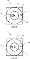
- a map of maximum pixel block sizes 150 is determined based on the spatial resolution distribution, such that for the first portion 142 of the distorted image frame 140 having the first spatial resolution, the maximum pixel block size is set to a first value 1502, and for the second portion 144 of the distorted image frame 140 having the second spatial resolution being lower than the first spatial resolution, the maximum pixel block size corresponding to the second portion 144 is set to a second value 1504 being lower than the first value 1502.
- An example of a map of maximum pixel block sizes 150 is illustrated in Fig. 1D .
- the distorted image frame 140 is encoded, using the block-based video encoding algorithm, wherein the map of maximum pixel block sizes 150 is used for defining maximum pixel block sizes for encoding blocks of the block-based video encoding algorithm.
- the map of maximum pixel block sizes 150 may be used for defining maximum sizes of coding units for the block-based video encoding algorithm. For instance, in case the block-based video encoding algorithm is h.265, the coding tree unit, CTU, size may set the maximum size of coding units. In case the block-based video encoding algorithm is AV1, the size of a superblock may set the maximum size of coding units.
- the block-based video encoding algorithm may use a smaller pixel block size for encoding blocks than the maximum pixel block size.
- the block-based video encoding algorithm typically uses a smaller pixel block size for encoding blocks than the maximum pixel block size in case the block-based video encoding algorithm determines that it is beneficial to the visual quality of the encoded video.
- objects in the first portion 142 of the distorted image frame 140 may be encoded using a large number of encoding blocks, thereby resulting in an encoded video having a high bitrate.
- a minimum pixel block size for encoding blocks associated with encoding the first portion 142 of the distorted image frame 140 may be set.
- the visual quality of objects in the first portion 142 will thereby be decreased in order to reduce the bitrate of the encoded video.
- the minimum pixel block size for encoding blocks may be set by defining the minimum sizes of prediction units, PU, and/or transform units, TU, of the block-based video encoding algorithm.
- a map of minimum pixel block sizes 160 corresponding to the distorted image frame 140 may be determined.
- An example of a map of maximum pixel block sizes 160 is illustrated in Fig. 1E .
- the map of minimum pixel block sizes 160 may comprise areas 162, 164 having different minimum pixel block sizes, and wherein the map of minimum pixel block sizes 160 is determined based on the spatial resolution distribution such that for the first portion 142 of the distorted image frame 140 having the first spatial resolution, the minimum pixel block size corresponding to the first portion 142 is set to a third value 1602 being lower than the first value 1502, and for the second portion 144 of the distorted image frame 140 having the second spatial resolution, the minimum pixel block size corresponding to the second portion 144 is set to a fourth value 1604 being lower than the second value 1504 and the third value 1602.
- the distorted image frame 140 may be encoded further using the map of minimum pixel block sizes 160 for defining minimum block sizes for encoding blocks of the block-based video encoding algorithm.
- Using the map of minimum pixel block sizes 160 for defining minimum block sizes for encoding blocks of the block-based video encoding algorithm may reduce a computational cost, file size and/or bandwidth associated with video encoding, and still allow a homogenous, and therefore improved, visual quality of the encoded video.
- the block-based video encoding algorithm may advantageously choose to use a higher compression ratio for the first portion 142 compared to the second portion 144.
- the first portion 142 and the second portion 144 in the distorted image frame 140 may form elliptical patterns radially extending from a reference position of the distorted image frame 140.
- the reference position may be a central position of the distorted image frame 140, as exemplified in Fig. 1C , and a radial distance from the reference position to the first portion 142 is smaller than a radial distance from the reference position to the second portion 144.
- a first area 152 of the map of maximum pixel sizes 150 corresponding to the first portion 142 of the distorted image frame 140 and a second area 154 of the map of maximum pixel sizes 150 corresponding to the second portion 144 of the distorted image frame 140 may form elliptical patterns radially extending from a reference position 1500 of the map of maximum pixel sizes 150.
- a radial distance between the reference position 1500 and the first area 152 may be smaller than a radial distance between the reference position 1500 and the second area 154.
- a first area 162 of the map of minimum pixel sizes 160 corresponding to the first portion 142 of the distorted image frame 140 and a second area 164 of the map of minimum pixel sizes 150 corresponding to the second portion 144 of the distorted image frame 140 may form elliptical patterns radially extending from a reference position 1600 of the map of minimum pixel sizes 160.
- a radial distance between the reference position 1600 and the first area 162 may be smaller than a radial distance between the reference position 1600 and the second area 164.
- the reference position 1600 in the map of minimum pixel block sizes 160 may correspond to the reference position 1500 in the map of maximum pixel block sizes 150.
- the spatial resolution distribution of the distorted image frame 140 may vary continuously over the distorted image frame 140, and that the corresponding map of maximum pixel block sizes 150 may vary accordingly.
- the description in relation to Fig. 1A-1E relates to a first portion 142 and a second portion 144, but may equally well relate to a larger number of portions.
- a skilled person realizes how to adapt the above description to account for additional portions in the distorted image frame 140 and/or a continuously varying spatial resolution distribution over the distorted image frame 140.
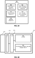
- Figure 2A illustrates an encoder 200.
- the encoder 200 is configured for encoding, using a block-based encoding algorithm, distorted image frames produced via at least one image sensor.
- the encoder 200 may be hardware and/or software implemented.
- the encoder 200 comprises a spatial resolution component 202 adapted to determine a spatial resolution distribution for the distorted image frames.
- the spatial resolution may be determined based on a lens polynomial of imaging optics used when capturing the distorted image frames 410.
- the imaging optics may be a wide-angle lens, e.g. a fisheye lens, or an optical dome.
- the encoder 200 further comprises a maximum pixel block sizes map component 204 adapted to determine a map of maximum pixel block sizes corresponding to the distorted image frames, wherein the map of maximum pixel block sizes is determined based on the spatial resolution distribution such that for a first portion of the distorted image frames having a first spatial resolution, the maximum pixel block size corresponding to the first portion is set to a first value, and for a second portion for the distorted image frames having a second spatial resolution being lower than the first spatial resolution, the maximum pixel block size corresponding to the second portion is set to a second value being lower than the first value.
- the encoder 200 further comprises a video encoding component 206 adapted to encode, using the block-based video encoding algorithm, the distorted image frames, wherein the map of maximum pixel block sizes is used by the block-based video encoding algorithm for defining maximum block sizes for encoding blocks of the block-based video encoding algorithm.
- the map of maximum pixel block sizes may be used for defining maximum block sizes of coding units of the block-based video encoding algorithm.
- the block-based encoding algorithm is h.265
- the coding tree unit, CTU size may define the maximum block sizes of the coding units.
- the block-based encoding algorithm is AV1
- the size of superblocks may define the maximum size of the coding units.
- the encoder 200 may further comprise a minimum pixel block sizes map component 208 adapted to determine a map of minimum pixel block sizes corresponding to the distorted image frames, the map of minimum pixel block sizes comprising areas having different minimum pixel block sizes, and wherein the map of minimum pixel block sizes is determined based on the spatial resolution distribution such that for the first portion of the distorted image frames having the first spatial resolution, the minimum pixel block size corresponding to the first portion is set to a third value being lower than the first value, and for the second portion of the distorted image frames having the second spatial resolution, the minimum pixel block size corresponding to the second portion is set to a fourth value being lower than the second value and the third value; and wherein the map of minimum pixel block sizes may be used by the block-based video encoding algorithm for defining minimum block sizes for encoding blocks of the block-based video encoding algorithm.
- the minimum block sizes of coding units may be defined by the minimum sizes of prediction units, PU, and/or transform units, TU, of the block-based video encoding algorithm.
- the encoder 200 may further comprise a stitching component 412 adapted to stitch image frames from a plurality of primary images, thereby producing the distorted image frames.
- the stitching component is separate from the encoder 200, wherein the distorted image frame comprises a plurality of captured images being stitched together before being received at the encoder 200.
- the encoder 200 may be comprised in a camera 210, as exemplified in Fig. 2B .
- the camera 210 further comprises at least one image sensor 212.
- the at least one image sensor 212 and the encoder 200 may communicate via a data bus 214.
- the camera 212 may further comprise imaging optics 216 through which images are captured by the at least one image sensor 212 of the camera 210.
- the imaging optics 214 may be a wide-angle lens.
- the wide-angle lens may be a fisheye lens.
- the wide-angle lens may be an optical dome.
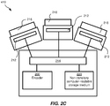
- the camera 410 may comprise a plurality of image sensors 212.
- the camera 410 may comprise a stitching component 412 (not shown in figure 2C since it is included in the encoder 200) adapted to stitch image frames from a plurality of primary images captured by the plurality of image sensors 212.
- Each of the plurality of image sensors 212 may, as exemplified in Fig. 2C , be associated with imaging optics 216.
- the imaging optics 216 may be similar to the imaging optics as described in relation to Fig. 2B .
- the imaging optics 216 in Fig. 2C may be traditional camera objectives adapted to reduce distortions in the primary images, i.e. the camera objective may be adapted to produce substantially rectilinear images as primary images.
- the plurality of image sensors 212 and the encoder 200 may communicate via a data bus 214.
- the camera 210, 410 may further comprise a non-transitory computer-readable storage medium 220 configured to store settings of the encoder, the map of maximum pixel block sizes, the map of minimum pixel block sizes, the distorted image frames, and/or the encoded video.
- the at least one image sensor 212, the encoder 220, and the non-transitory computer-readable storage medium 220 may communicate via the data bus 214.
- the encoder 200 may be comprised in an external computer and/or server configured to receive distorted image frames from the camera 210, 410.
- Figure 3 is a block scheme of a method 300 for encoding, using a block-based video encoding algorithm, distorted image frames 140 produced via at least one image sensor 212.
- the method 300 comprises determining 302 a spatial resolution distribution for the distorted image frames 140.
- the distorted image frames 140 may be produced by capturing 312 by one image sensor 212 through a wide-angle lens, and the spatial resolution distribution may be determined based on a lens polynomial of the wide-angle lens.
- the wide-angle lens may be a fisheye lens.
- the distorted image frames 140 may be produced by capturing 314 by one image sensor 212 through an optical dome, and the spatial resolution distribution may be determined based on a lens polynomial of the optical dome.
- Each distorted image frame 140 may be produced by a stitching 316, based on a projection algorithm, of a plurality of primary image frames captured by one or more image sensors 212.
- the spatial resolution distribution may be determined based on the projection algorithm.
- the method further comprises determining 304 a map of maximum pixel block sizes 150 corresponding to the distorted image frames 140.
- the map of maximum pixel block sizes 150 is determined based on the spatial resolution distribution such that for a first portion 142 of the distorted image frames 140 having a first spatial resolution, the maximum pixel block size corresponding to the first portion 142 is set to a first value 1502, and for a second portion 144 of the distorted image frames 140 having a second spatial resolution being lower than the first spatial resolution, the maximum pixel block size corresponding to the second portion 144 is set to a second value 1504 being lower than the first value 1502.
- the map of maximum pixel block sizes 150 may comprise areas having different maximum pixel block sizes.
- the first portion 142 may be a central portion of the distorted image frames 140.
- the second portion 144 may be an outer portion of the distorted image frames 140.
- the method 300 further comprises encoding 306, using the block-based video encoding algorithm, the distorted image frames 140, wherein the map of maximum pixel block sizes 150 is used for defining maximum block sizes for encoding blocks of the block-based video encoding algorithm.
- the block-based video encoding algorithm may be h.265 or AV1, and the map of maximum pixel block sizes 150 may be used for defining maximum sizes of coding units of the block-based video encoding algorithm.
- the method 300 may further comprise determining 308 a map of minimum pixel block sizes 160 corresponding to the distorted image frames 140, wherein the map of minimum pixel block sizes 160 comprises areas 162, 164 having different minimum pixel block sizes, and wherein the map of minimum pixel block sizes 160 is determined based on the spatial resolution distribution such that for the first portion 142 of the distorted image frames 140 having the first spatial resolution, the minimum pixel block size corresponding to the first portion 142 is set to a third value 1602 being lower than the first value 1502, and for a second portion 144 of the distorted image frames 140 having the second spatial resolution, the minimum pixel block size corresponding to the second portion 144 is set to a fourth value 1604 being lower than the second value 1504 and the third value 1602; and wherein, in the step of encoding 306 the distorted image frames 140, the map of minimum pixel block sizes 160 is used for defining minimum block sizes for encoding blocks of the block-based video encoding algorithm.
- the block-based video encoding algorithm may be h.265, and the map of minimum pixel block sizes 160 may be used for defining the minimum sizes of prediction units, PU, and/or transform units, TU, of the block-based video encoding algorithm.
- a first area 152 of the map of maximum pixel sizes 150 corresponding to the first portion 142 of the distorted image frame 140 and a second area 154 of the map of maximum pixel sizes 150 corresponding to the second portion 144 of the distorted image frame 140 may form elliptical patterns radially extending from a reference position 1500 of the map of maximum pixel sizes 150, and a radial distance between the reference position 1500 and the first area 152 may be smaller than a radial distance between the reference position 1500 and the second area 154.
- the method 300 have above been described and shown in Fig. 3 in a sequential manner, however the steps of the method 300 may be performed in other orders than described here.
- the map of minimum pixel block sizes 160 may be determined prior to, or simultaneously with, the map of maximum pixel block sizes 150.
- the distorted image frame 140 discussed in relation to Fig. 1C may alternatively be produced by a stitching, based on a projection algorithm, of a plurality of primary image frames captured by one or more image sensors.
- the spatial resolution distribution may, for a stitched image, be based on the projection algorithm.
- the third value 1602 is shown as being smaller than the second value 1504, however, it is to be understood that the second value 1504 may be smaller than the third value 1602.
Priority Applications (6)
| Application Number | Priority Date | Filing Date | Title |
|---|---|---|---|
| EP19174349.1A EP3739880A1 (de) | 2019-05-14 | 2019-05-14 | Verfahren, vorrichtung und computerprogrammprodukt zur codierung eines verzerrten bildrahmens |
| KR1020200024384A KR102396570B1 (ko) | 2019-05-14 | 2020-02-27 | 왜곡된 이미지 프레임을 인코딩하기 위한 방법, 장치 및 컴퓨터 프로그램 제품 |
| US16/807,208 US11146817B2 (en) | 2019-05-14 | 2020-03-03 | Method, device and computer program product for encoding a distorted image frame |
| TW109107355A TWI801724B (zh) | 2019-05-14 | 2020-03-06 | 用於編碼失真影像圖框的方法、裝置及電腦程式產品 |
| JP2020081613A JP7125446B2 (ja) | 2019-05-14 | 2020-05-02 | 歪み画像フレームをエンコードするための方法、デバイス、およびコンピュータプログラム製品 |
| CN202010387614.5A CN111953982B (zh) | 2019-05-14 | 2020-05-09 | 编码失真的图像帧的方法、设备和介质 |
Applications Claiming Priority (1)
| Application Number | Priority Date | Filing Date | Title |
|---|---|---|---|
| EP19174349.1A EP3739880A1 (de) | 2019-05-14 | 2019-05-14 | Verfahren, vorrichtung und computerprogrammprodukt zur codierung eines verzerrten bildrahmens |
Publications (1)
| Publication Number | Publication Date |
|---|---|
| EP3739880A1 true EP3739880A1 (de) | 2020-11-18 |
Family
ID=66542112
Family Applications (1)
| Application Number | Title | Priority Date | Filing Date |
|---|---|---|---|
| EP19174349.1A Pending EP3739880A1 (de) | 2019-05-14 | 2019-05-14 | Verfahren, vorrichtung und computerprogrammprodukt zur codierung eines verzerrten bildrahmens |
Country Status (6)
| Country | Link |
|---|---|
| US (1) | US11146817B2 (de) |
| EP (1) | EP3739880A1 (de) |
| JP (1) | JP7125446B2 (de) |
| KR (1) | KR102396570B1 (de) |
| CN (1) | CN111953982B (de) |
| TW (1) | TWI801724B (de) |
Families Citing this family (1)
| Publication number | Priority date | Publication date | Assignee | Title |
|---|---|---|---|---|
| US20230300338A1 (en) * | 2022-03-16 | 2023-09-21 | Apple Inc. | Resolution-based video encoding |
Citations (1)
| Publication number | Priority date | Publication date | Assignee | Title |
|---|---|---|---|---|
| EP3301920A1 (de) * | 2016-09-30 | 2018-04-04 | Thomson Licensing | Verfahren und vorrichtung zur codierung/decodierung eines omnidirektionalen videos |
Family Cites Families (23)
| Publication number | Priority date | Publication date | Assignee | Title |
|---|---|---|---|---|
| JP4404340B2 (ja) | 2003-09-22 | 2010-01-27 | Kddi株式会社 | 適応形状画像符号化装置および復号装置 |
| US20140254659A1 (en) | 2013-03-11 | 2014-09-11 | Mediatek Inc. | Video coding method using at least evaluated visual quality and related video coding apparatus |
| JP2015050661A (ja) * | 2013-09-02 | 2015-03-16 | キヤノン株式会社 | 符号化装置、符号化装置の制御方法、及び、コンピュータプログラム |
| JP2015115901A (ja) | 2013-12-13 | 2015-06-22 | キヤノン株式会社 | 符号化装置、符号化装置の制御方法、及び、コンピュータプログラム |
| GB2525851B (en) * | 2014-04-30 | 2017-03-29 | Canon Kk | Method and device for encoding a sub-aperture image of a set of sub-aperture images obtained from a plenoptic image |
| EP3021583B1 (de) | 2014-11-14 | 2019-10-23 | Axis AB | Verfahren zur Identifizierung relevanter Bereiche in Digitalbildern, Verfahren zur Codierung von Digitalbildern und Codierungssystem |
| WO2016168415A1 (en) | 2015-04-15 | 2016-10-20 | Lytro, Inc. | Light guided image plane tiled arrays with dense fiber optic bundles for light-field and high resolution image acquisition |
| US10225546B2 (en) * | 2016-02-26 | 2019-03-05 | Qualcomm Incorporated | Independent multi-resolution coding |
| US9721393B1 (en) * | 2016-04-29 | 2017-08-01 | Immersive Enterprises, LLC | Method for processing and delivering virtual reality content to a user |
| US11019257B2 (en) * | 2016-05-19 | 2021-05-25 | Avago Technologies International Sales Pte. Limited | 360 degree video capture and playback |
| US10979691B2 (en) | 2016-05-20 | 2021-04-13 | Qualcomm Incorporated | Circular fisheye video in virtual reality |
| US10887621B2 (en) * | 2016-07-08 | 2021-01-05 | Vid Scale, Inc. | 360-degree video coding using geometry projection |
| US20190238888A1 (en) * | 2017-07-17 | 2019-08-01 | Ki Baek Kim | Image data encoding/decoding method and apparatus |
| US10917564B2 (en) * | 2016-10-12 | 2021-02-09 | Qualcomm Incorporated | Systems and methods of generating and processing files for partial decoding and most interested regions |
| US10620441B2 (en) * | 2016-12-14 | 2020-04-14 | Qualcomm Incorporated | Viewport-aware quality metric for 360-degree video |
| JP6922215B2 (ja) | 2016-12-27 | 2021-08-18 | 富士通株式会社 | 動画像符号化装置 |
| US20190364261A1 (en) * | 2017-01-10 | 2019-11-28 | Lg Electronics Inc. | Method for transmitting 360-degree video, method for receiving 360-degree video, apparatus for transmitting 360-degree video and apparatus for receiving 360-degree video |
| US11172208B2 (en) * | 2017-02-28 | 2021-11-09 | Nokia Technologies Oy | Method and apparatus for improving the visual quality of viewport-based omnidirectional video streaming |
| CN110521207A (zh) * | 2017-03-13 | 2019-11-29 | 韩国电子通信研究院 | 用于视频编码/解码的基于非典型块的运动预测和补偿的方法及其装置 |
| US10904531B2 (en) | 2017-03-23 | 2021-01-26 | Qualcomm Incorporated | Adaptive parameters for coding of 360-degree video |
| WO2018206551A1 (en) * | 2017-05-09 | 2018-11-15 | Koninklijke Kpn N.V. | Coding spherical video data |
| CN107396081B (zh) | 2017-06-19 | 2019-04-12 | 深圳市铂岩科技有限公司 | 针对全景视频的优化编码方法及装置 |
| WO2019009667A1 (ko) * | 2017-07-06 | 2019-01-10 | 가온미디어 주식회사 | 동기화된 영상의 처리 방법 및 그 장치 |
-
2019
- 2019-05-14 EP EP19174349.1A patent/EP3739880A1/de active Pending
-
2020
- 2020-02-27 KR KR1020200024384A patent/KR102396570B1/ko active IP Right Grant
- 2020-03-03 US US16/807,208 patent/US11146817B2/en active Active
- 2020-03-06 TW TW109107355A patent/TWI801724B/zh active
- 2020-05-02 JP JP2020081613A patent/JP7125446B2/ja active Active
- 2020-05-09 CN CN202010387614.5A patent/CN111953982B/zh active Active
Patent Citations (1)
| Publication number | Priority date | Publication date | Assignee | Title |
|---|---|---|---|---|
| EP3301920A1 (de) * | 2016-09-30 | 2018-04-04 | Thomson Licensing | Verfahren und vorrichtung zur codierung/decodierung eines omnidirektionalen videos |
Non-Patent Citations (2)
| Title |
|---|
| "Emerging Topics in Computer Vision", 1 January 2014, PRENTICE HALL PROFESSIONAL TECHNICAL REFERENCE, ISBN: 978-0-387-31439-6, article DAVIDE SCARAMUZZA: "Omnidirectional Camera : A Reference Guide", pages: 552 - 560, XP055639434, DOI: 10.1007/978-0-387-31439-6_488 * |
| YU MATT ET AL: "A Framework to Evaluate Omnidirectional Video Coding Schemes", 2015 IEEE INTERNATIONAL SYMPOSIUM ON MIXED AND AUGMENTED REALITY, IEEE, 29 September 2015 (2015-09-29), pages 31 - 36, XP032809476, DOI: 10.1109/ISMAR.2015.12 * |
Also Published As
| Publication number | Publication date |
|---|---|
| TW202101966A (zh) | 2021-01-01 |
| KR102396570B1 (ko) | 2022-05-10 |
| JP2020205582A (ja) | 2020-12-24 |
| CN111953982B (zh) | 2023-06-16 |
| US11146817B2 (en) | 2021-10-12 |
| TWI801724B (zh) | 2023-05-11 |
| US20200366934A1 (en) | 2020-11-19 |
| CN111953982A (zh) | 2020-11-17 |
| KR20200131729A (ko) | 2020-11-24 |
| JP7125446B2 (ja) | 2022-08-24 |
Similar Documents
| Publication | Publication Date | Title |
|---|---|---|
| US9185271B2 (en) | Imaging device detecting motion vector | |
| US8208716B2 (en) | Stereo vision system and stereo vision processing method | |
| WO2013032769A1 (en) | Producing focused videos from single captured video | |
| US9253411B2 (en) | Image processing apparatus, image processing method and image communication system | |
| CN109688413B (zh) | 以支持辅助帧的视频编码格式编码视频流的方法和编码器 | |
| TW201812698A (zh) | 具有基於特徵的重影去除的陣列照相機影像組合 | |
| CN108495066B (zh) | 广角镜头的畸变矫正方法、装置及系统 | |
| US11146817B2 (en) | Method, device and computer program product for encoding a distorted image frame | |
| CN108156383B (zh) | 基于相机阵列的高动态十亿像素视频采集方法及装置 | |
| US20200267385A1 (en) | Method for processing synchronised image, and apparatus therefor | |
| Chao et al. | Pre-demosaic light field image compression using graph lifting transform | |
| US6285791B1 (en) | Transmission method for video or moving pictures by compressing block differences | |
| CN112543330A (zh) | 模糊隐私遮蔽 | |
| US8787689B2 (en) | Apparatus and method for correction of distortion in digital image data | |
| JP2011023885A (ja) | 映像符号化装置及び映像符号化方法 | |
| EP3131295A1 (de) | Videocodierungsverfahren und -system | |
| US7683935B2 (en) | Imaging device | |
| US11682190B2 (en) | Method, system, and device for detecting an object in a distorted image | |
| JP2006157432A (ja) | 立体画像撮影装置及び立体画像の撮影方法 | |
| KR20190127543A (ko) | 비디오 시퀀스에서 모션을 감지하기 위한 방법 | |
| JP2020205582A5 (de) | ||
| CN112637601B (zh) | 基于鱼眼全景视频的编码方法及装置 | |
| CN112203023A (zh) | 一种十亿像素视频生成方法及装置、设备、介质 | |
| EP3506633A1 (de) | Videocodierungsverfahren und -system | |
| EP4177823A1 (de) | Erzeugung eines ausgangsbildes einer szene aus mehreren quellenbildern, die von verschiedenen kameras aufgenommen werden |
Legal Events
| Date | Code | Title | Description |
|---|---|---|---|
| PUAI | Public reference made under article 153(3) epc to a published international application that has entered the european phase |
Free format text: ORIGINAL CODE: 0009012 |
|
| STAA | Information on the status of an ep patent application or granted ep patent |
Free format text: STATUS: REQUEST FOR EXAMINATION WAS MADE |
|
| 17P | Request for examination filed |
Effective date: 20200127 |
|
| AK | Designated contracting states |
Kind code of ref document: A1 Designated state(s): AL AT BE BG CH CY CZ DE DK EE ES FI FR GB GR HR HU IE IS IT LI LT LU LV MC MK MT NL NO PL PT RO RS SE SI SK SM TR |
|
| AX | Request for extension of the european patent |
Extension state: BA ME |
|
| RAP1 | Party data changed (applicant data changed or rights of an application transferred) |
Owner name: AXIS AB |
|
| STAA | Information on the status of an ep patent application or granted ep patent |
Free format text: STATUS: EXAMINATION IS IN PROGRESS |
|
| 17Q | First examination report despatched |
Effective date: 20210927 |