EP3739698A1 - Method and device for inserting terminals mounted on the end of wires twisted with one another - Google Patents
Method and device for inserting terminals mounted on the end of wires twisted with one another Download PDFInfo
- Publication number
- EP3739698A1 EP3739698A1 EP20174040.4A EP20174040A EP3739698A1 EP 3739698 A1 EP3739698 A1 EP 3739698A1 EP 20174040 A EP20174040 A EP 20174040A EP 3739698 A1 EP3739698 A1 EP 3739698A1
- Authority
- EP
- European Patent Office
- Prior art keywords
- terminal
- clamp
- robot
- wire
- socket
- Prior art date
- Legal status (The legal status is an assumption and is not a legal conclusion. Google has not performed a legal analysis and makes no representation as to the accuracy of the status listed.)
- Granted
Links
Images


Classifications
-
- H—ELECTRICITY
- H01—ELECTRIC ELEMENTS
- H01R—ELECTRICALLY-CONDUCTIVE CONNECTIONS; STRUCTURAL ASSOCIATIONS OF A PLURALITY OF MUTUALLY-INSULATED ELECTRICAL CONNECTING ELEMENTS; COUPLING DEVICES; CURRENT COLLECTORS
- H01R43/00—Apparatus or processes specially adapted for manufacturing, assembling, maintaining, or repairing of line connectors or current collectors or for joining electric conductors
- H01R43/28—Apparatus or processes specially adapted for manufacturing, assembling, maintaining, or repairing of line connectors or current collectors or for joining electric conductors for wire processing before connecting to contact members, not provided for in groups H01R43/02 - H01R43/26
-
- G—PHYSICS
- G01—MEASURING; TESTING
- G01B—MEASURING LENGTH, THICKNESS OR SIMILAR LINEAR DIMENSIONS; MEASURING ANGLES; MEASURING AREAS; MEASURING IRREGULARITIES OF SURFACES OR CONTOURS
- G01B11/00—Measuring arrangements characterised by the use of optical techniques
- G01B11/002—Measuring arrangements characterised by the use of optical techniques for measuring two or more coordinates
-
- H—ELECTRICITY
- H01—ELECTRIC ELEMENTS
- H01R—ELECTRICALLY-CONDUCTIVE CONNECTIONS; STRUCTURAL ASSOCIATIONS OF A PLURALITY OF MUTUALLY-INSULATED ELECTRICAL CONNECTING ELEMENTS; COUPLING DEVICES; CURRENT COLLECTORS
- H01R43/00—Apparatus or processes specially adapted for manufacturing, assembling, maintaining, or repairing of line connectors or current collectors or for joining electric conductors
- H01R43/20—Apparatus or processes specially adapted for manufacturing, assembling, maintaining, or repairing of line connectors or current collectors or for joining electric conductors for assembling or disassembling contact members with insulating base, case or sleeve
Definitions
- the invention relates to the field of manufacturing electrical harnesses formed from a plurality of wires, the ends of which are inserted into connectors.
- These machines include an upstream part in which a wire is cut to a desired length. Both ends of the wire are stripped and usually crimped with a terminal to form a termination for making electrical contact.
- threads are in the form of single threads or, in the case which concerns the invention, in the form of a pair of threads twisted together.
- Each pair of wires therefore includes two terminals at each of its ends.
- the object of the invention is to provide a method and a device making it possible to insert, according to an original sequence, two terminals crimped respectively at the end of two wires twisted together.
- This angular deviation allows movements of the insertion clamp which are reduced, but of sufficient magnitude, to carry out the operations of measuring the position of the terminals as well as the insertion of the latter into their respective cells without it being necessary to grasping the lugs and not releasing the wires until the lugs are in place in the cells.
- the method according to the invention can also comprise, alone, or in combination, the following characteristics:
- the angular difference between the first and the second wire is created by moving the first wire supporting the first terminal disposed longitudinally in front of the second terminal.
- the longitudinal offset between the first and the second terminal is between 3mm and 10mm.
- the angular difference between the first and the second wire is between 45 ° and 90 °.
- steps l 'and L' at the end of steps l and L respectively, when a terminal is completely inserted, a force of given amplitude is exerted using the robot in the direction opposite to the direction of insertion and an alert is emitted when the application of this force has the effect of making said terminal emerge from the socket.
- an insertion force is measured and an alert is issued when said insertion force is greater or less than predetermined thresholds as a function of the insertion depth.
- the position of the first retaining clip is adjusted relative to the position of the second retaining clip so that the distance between the longitudinal axis of the first terminal and the longitudinal axis of the second terminal is substantially equal to the distance between the axis of insertion of the first terminal in the first socket and the axis of insertion of the second terminal in the second socket.
- a step C ′ after having completed step C and prior to step D, using a centering device, the wires situated between the terminals and the insertion clamp are positioned substantially in a predetermined plane.
- the coordinates and the orientation of the insertion clamp supported by the six-axis robot are also known during and at the end of each movement of the robot.
- the axis OX or XX ′ represents the direction of insertion of the terminal in the socket of the connector into which it is desired to introduce said terminal.
- the direction OZ, or ZZ ' represents the vertical direction and the direction OY, or YY', represents the transverse direction.
- the directions OY and OZ are perpendicular to each other. It is observed here that, in the main frame of the insertion device, the OXYZ frame changes with each change of socket.
- one or more elements of the device can be arranged in a sub-frame of their own and whose coordinates are known with respect to the main frame of the machine and with respect to the OXYZ frame of the cell. to equip.
- the passage from a sub-frame to the main frame of the device or to the OXYZ frame of the cell is then done by a simple change of frame determined by calculation by the central unit.
- the crimping operations of the terminal considered to be rigid and non-deformable, on the end of the wire, considered to be susceptible to deformation, are carried out upstream of the device. insertion.
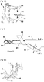
- step A which is the first step of the process itself, the son 21 and 22 are gripped by a first clamp and a second holding clamp, respectively 71 and 72. It will be observed that the son 21 and 22 are twisted in upstream of the retaining clamps 71 and 72 and that the latter grip each of the wires in the end part of the braid in which the two wires are free. Lugs, 11 and 12 respectively, are crimped at the end of the wires 21 and 22. The longitudinal axis of each of the lugs 11 and 12 is marked respectively by the lines L 1 L ' 1 and L 2 L' 2 . The axis of the holding clamps at the gripping points is predetermined in the reference OXYZ.
- Step A is generally preceded by a series of steps leading to the pre-positioning of the free parts of the two wires 21 and 22, so that they can be gripped separately from one another by the two holding clamps 71 and 72.
- the holding clamps 71 and 72 are arranged so that, at the point of gripping, the axis of the clamps is aligned with the insertion axis XX '.
- the first and the second holding clamp are able to rotate the wire around the axis of the wire.
- the terminal Prior to the step, the terminal is angularly pre-positioned around the direction of insertion so that, during the steps of aligning the terminals with the cells of the connector, the terminal is rotated around the axis d insertion according to a predetermined direction of rotation.
- the wires and the terminals are represented by convention in the horizontal plane XOY of the drawing sheet perpendicular to the direction ZZ '. It goes without saying, as will be explained later, that the wires and the terminals do not strictly belong to the same plane because of the deformations of the wires between the point of entry of the wire and the terminal and that the axes L 1 L ' 1 and L 2 L' 2 are therefore not strictly parallel to each other nor coplanar.
- the retaining clamps 71 and 72 are positioned so that, at the end of step A, the axes L 1 L ' 1 and L 2 L' 2 are substantially spaced from each other by a distance d, equal to the distance between the axes X 1 X ' 1 and X 2 X' 2 of the cells 31 and 32 (see figures 13 and following) in which the terminals 11 and 12 are intended to be inserted.
- the axes X 1 X ' 1 and X 2 X' 2 are generally parallel to each other.
- step B shown in figure 2 , the first retaining clip 71 is translated relative to the second retaining clip 72 in a direction parallel to the direction XX 'of insertion of the terminal in the cell, so as to create a longitudinal offset by a given value D between the end of the first terminal 11 and the end of the second terminal 12.
- This distance D can usefully be between 3mm and 10mm.
- step C using an insertion clamp 40, the first and the second thread, respectively 11 and 12, are simultaneously grasped at a grasping point 41 arranged between the holding clamps, respectively 71 and 72, and the terminals, respectively 11 and 12.
- the insertion clamp 40 is mounted on the head of a six-axis robot (not shown), capable of moving said insertion clamp 40 in translation in three independent directions XX ', YY', ZZ 'and in rotation. around each of these three directions.
- a jack (not shown) drives the insertion clamp 40 in translation in the transverse direction on the head of the robot. As will be seen below (step K), this sliding makes it possible to move the insertion clamp 40 without it being necessary to move the head of the robot.
- the control of the movements of the insertion clamp in the OXYZ frame is provided by a central unit, connected to the various organs of the insertion device, comprising coded instructions for analyzing the images coming from said cameras and controlling the movements of the first and the second retaining clamp, of the recovery clamp, of the separation means and of the robot head supporting the insertion clamp.
- the insertion clamp 40 comprises two jaws which simultaneously grip the threads 11 and 12 so that the threads do not undergo any displacement with respect to the insertion clip 40 during the execution of the subsequent steps of implementing the method according to l 'invention.
- the surface of the jaws can usefully be covered with a coating comprising roughness calibrated so as not to damage the insulation covering the electrically conductive part.
- step C ′ the deviations of the position of the terminals 11 and 12 with respect to a horizontal plane are reduced without however being brought back to zero.
- step D the robot head moves the insertion clamp to the right of a separation means 5.
- the object of this separation means 5 is to create an angular difference ⁇ , not zero, between the first and the second wire, respectively 11 and 12, as illustrated in figure 5 .
- the separation means is here formed of a rod 5 which is inserted between the two wires 21 and 22, between the insertion clamp 40 and the terminals 11 and 12, without coming into contact with one of them. .
- the rod 5 then presses on one of the two threads and exerts on the latter a pressure capable of creating a permanent angular deformation of said thread, so that the two threads form an angular difference of value ⁇ between them.
- This angular deviation can be created indiscriminately by moving the rod or by moving the head of the robot supporting the insertion clamp.
- the value of the angular deviation ⁇ can vary from one wire to another because of the elastic stresses which have for object to return the wire on which the pressure of the rod is exerted to its original position. Also, as will be seen below, it may prove useful to establish an average ⁇ m of this value. Knowing the characteristics of the wires to be inserted, the action of the rod is adjusted so that the average value ⁇ m of the residual angular difference between the two wires 11 and 12 is between 45 ° and 90 °.
- the angular difference between the wires is intended to allow the terminals of each of the wires to be introduced separately into the field of the cameras in order to determine the orientation in space of each of the terminals.
- This mean angular deviation ⁇ m is adjusted experimentally as a function of the size of the cameras and of the arrangement of the cells so that the space available between the wires is sufficient to carry out the steps E to L which follow.
- action will be taken on the wire supporting the first terminal 11, the end of which is disposed longitudinally in front of the second terminal 12.
- the figure 6 illustrates, in the orthonormal space OXYZ, the respective positions of the axis L 2 L ' 2 of the second terminal 12 defined by a vector V 2 , with respect to the direction of insertion X 2 X' 2 of the second terminal in the second socket 32, and to the angular orientation of the second terminal around the insertion axis X 2 X ' 2 .
- the second terminal 12 projects along a profile 12a.
- the projection V 21 of the vector V 2 in the plane P 1 makes an angle ⁇ 21 with a line X 21 X '21 belonging to the plane P 1 and parallel to the direction of insertion X 2 X' 2 of the second terminal 12 in the second cell 32.
- the second terminal 12 projects along a profile 12b.
- V 22 the projection of the vector V 2 in the plane P 2, makes an angle ⁇ with a straight line 22 X 22 X '22 in the plane P 2 parallel to the direction of insertion X 2 X' 2.
- the lines X 21 X '21 and X 22 X' 22 are respectively distant by a value t 1 and t 2 in the directions YY 'and ZZ' from the direction of insertion X 2 X ' 2 of the terminal in the second alveolus 32.
- the second terminal 12 makes an angle ⁇ 23 around its longitudinal axis L 2 L ' 2 relative to the angular position of the second terminal 12 around this same longitudinal axis when the latter is inserted into the second cell 32.
- Steps E and F illustrated in figures 7 to 12 , aim to determine the values of the angles ⁇ 21 , ⁇ 22 and ⁇ 23 , of the translations t 21 and t 22 , as well as the position the end of the second terminal, so as to make the angular corrections allowing the longitudinal axis L 2 L ' 2 of the second terminal 12 to be aligned with the insertion axis X 2 X' 2 of the second terminal 12 in the second socket 32.
- the values ⁇ 11 , ⁇ 12 , the translations t 11 and t 12 and the angular value ⁇ 13 are determined , making it possible to align the longitudinal axis L 1
- the 1 of the first terminal 11 with the insertion axis X 1 X ' 1 of the first terminal 11 in the first cell 31, are defined in the same way in the reference OXYZ.
- the figures 7, 8, 8a and 9 schematically illustrate step E leading to the determination of the positioning in the OXYZ frame of the axis L 2 L ' 2 of the second terminal 12.
- this determination provides for the use of a first linear camera 81 and of a second linear camera 82, arranged so that the fields of these cameras are oriented respectively in the directions YY 'and ZZ'.
- the cameras are fixed in the OXYZ frame.
- Line cameras include one or more lines of CCD or CMOS sensors, and provide a one-dimensional (one line) image of the section of an object in the direction of the camera field.
- a first light emitter 83 is arranged so as to create with the first line camera 81 a light curtain 87 forming a plane perpendicular to the direction of insertion X'X.
- a second light emitter 84 is arranged so as to create with the second line camera 82 a light curtain 88 forming a plane perpendicular to the direction of insertion X'X.
- the two light curtains 87 and 88 overlap to form a single light curtain.
- the second line camera 82 and the second light emitter 84 are shown in dotted lines in the same plane as the first line camera 81 and that the first light emitter 83. Also, for a good understanding of the following , the illustration of these two light devices should be subjected to an imaginary rotation of 90 ° around the insertion axis XX '.
- the robot head approaches the second terminal 12 in the light curtain 87/88 so as to present a rear section of the second terminal 12 in the light curtain, as shown in figure 8
- the image obtained by the first linear camera 81 makes it possible to determine the coordinates a z of the center a of this rear section on the axis ZZ '.
- the image obtained by the second linear camera 82 makes it possible to determine the coordinates a y of the center a of said rear section on the axis YY '.
- the center a of the rear section of the second terminal which is located on the longitudinal axis L 2 L ' 2 of the terminal, has for coordinates (a y , a z ) in a plane OYZ perpendicular to the direction X 2 X' 2 and passing through the rear section of the second terminal.
- the second terminal 12 is moved rearward in the direction X 2 X ' 2 by a predetermined value e, so as to position a front section of the second terminal 12, distinct from the rear section , in the light curtain, as shown in figure 8a .
- the image obtained by the first linear camera 81 makes it possible to determine the coordinates b z of the center b of this front section on the axis ZZ '.
- the image obtained by the second linear camera 82 makes it possible to determine the coordinates b y of the center b of said front section on the axis YY '.
- the center b of the front section which is also located on the longitudinal axis L 2 L ' 2 of the second terminal 12, has for coordinates (b y , b z ) in the plane OYZ perpendicular to the direction XX' and passing through the front section of the second terminal 12.
- the determination of the position of the front end of the second terminal 12 along the insertion axis X 2 X ' 2 is obtained when the latter crosses the light field 85 when the second terminal 12 is inserted or withdrawn from the field of the cameras.
- the angular orientation a 23 of the second terminal 12 is determined after having aligned the axis L 2 L ' 2 with the direction of introduction X 2 X' 2 by performing the angular corrections ⁇ 21 and ⁇ 22 .
- the second terminal 12 is maintained in the light curtain and said terminal 12 is rotated around the axis X 2 X ' 2 , coincident at this instant with the longitudinal axis L 2 L' 2 , until l 'one obtains a maximum or minimum value of the projections of the terminal in the directions OY and OZ representative of a known angular position of the terminal around the axis X 2 X' 2 .
- step E the values of the angles ⁇ 21 , ⁇ 22 , ⁇ 23 , of the translations t 21 , t 22 , as well as the position of the end of the central unit are recorded in the memory of the central unit.
- the second pod in the OXYZ space.
- Step F is then started , by rotating the insertion clamp 40 using the robot by the predetermined angle - ⁇ m substantially equal and opposite to the angular difference ⁇ imposed in step D between the first and the second wire, respectively 21 and 22, as illustrated in figure 10 .
- the first terminal 11 is presented in the field of the first camera 81 and of the second camera 82.
- step F the values of angles ⁇ 11 , ⁇ 12 , ⁇ 13 , translations t 11 , t 12 , as well as the position of the end of the first terminal 11 in the OXYZ space.
- step G and with reference to figure 13 the insertion clamp 40 is moved using the robot, performing the rotations of values - ⁇ 11 , - ⁇ 12 , and the translations of value t 11 and t 12 so as to confuse the longitudinal axis L 1 L ' 1 of the first terminal 11 with the insertion axis X 1 X' 1 of said first terminal 11 in the first cell 31.
- the angular position of the terminal is then adjusted around its longitudinal axis L 1 L ' 1 by the angular correction - ⁇ 13 .
- the first terminal 11 is preinserted into the first cell 31 to a given depth p 1 , as illustrated in figure 14 .
- the depth p 1 is less than the value of the shift D operated in step B.
- the first terminal 11 retains only one degree of freedom along the insertion axis X 1 X ' 1 and remains locked in rotation around this same axis X 1 X ' 1 as well as in translation and in rotation about the axes OY and OZ.
- step H the insertion clamp is rotated by an angle substantially equal to the angle - ⁇ m given in step D.
- the orientation in space since the second terminal is known (Step E), it suffices to orient the second terminal according to the direction of introduction. This movement has the effect of replacing the axis L 1 L ' 1 of the second terminal 12 substantially in the axis of introduction of the second terminal into the socket 32 as illustrated in figure 15
- the rotations of values - ⁇ 21 , - ⁇ 22 , and the translations of value t 21 and t 22 are carried out so as to confuse the longitudinal axis (L 2 L ' 2 ) of the second terminal 12 with the axis of insertion (X 2 X ' 2 ) of the second terminal 12 in the second socket 32.
- the angular position of the terminal is then adjusted around its longitudinal axis L 2 L' 2 of the angular correction - ⁇ 23 , and the angular position is pre-inserted the second terminal 12 in the second cell 32 to a given depth p 2 , while continuing the insertion of the first terminal 11, as illustrated in figure 16 .
- step A the distance d between the holding clamps 71 and 72 to a value close to the distance between the axes X 1 X ' 1 and X 2 X' 2 .
- step C the use of the centering device provided in step C 'makes it possible to reduce the value of the angular corrections ⁇ 11 , ⁇ 12 , ⁇ 21 and ⁇ 22 .
- step I using the robot, the insertion clamp 40 is moved in the direction of introduction XX 'and the first and the second terminal are simultaneously inserted into their respective cells 31 and 32 until that the first terminal 11 is fully inserted, as shown in figure 17 .
- an insertion force of the terminals is measured using a strain gauge (not shown) and an alert is issued when said force insertion is greater or less than predetermined thresholds depending on the insertion depth. Too high a value signifies the presence of a locking primer capable of causing the wires to buckle if the insertion pliers continue to advance. And a value that is too low may mean that the insertion of one of the wires is no longer done correctly under the effect of a buckling of the latter.
- step I at the end of step I, during a step I ' illustrated in figure 18 , using the robot, a force of given amplitude is exerted on the first wire 21 and reduced in the direction opposite to the direction of insertion to ensure that the first terminal 11 is properly inserted into its socket. An alert is issued when the application of this force has the effect of making said first terminal 11 emerge from the cell 31, allowing movement of the insertion clamp 40 in the direction of extraction.
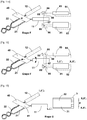
- step J illustrated in figure 19 the first 11 and the second wire 12 are simultaneously grasped using a recovery pliers 73 at the level of the twisted part upstream of the insertion pliers 40.
- the recovery pliers 73 is arranged on the head of the robot, downstream of the insertion clamp 40.
- step K illustrated in figure 20 while maintaining, using the recovery clamp 72, the wires 21 and 22 in the position obtained at the end of step I, the insertion clamp 40 is released and, without moving the head of the robot, said insertion clamp 40 is slid in order to grasp the single second wire 22 at a grasping point located between the recovery clamp 72 and the second terminal 12. Then the recovery clamp 73 is removed, as illustrated to the figure 21 .
- step L shown in figure 22 , the insertion clamp 40 is moved in the direction of insertion until the second terminal 12 is fully inserted.
- step L can be followed by a control step L ' illustrated in figure 23 , similar to step I 'previously described.
- the figure 24 marks the end of the introduction of the two pods 11 and 12 into their respective cells 31 and 32, making it possible to release the insertion clamp 40 and to replace the robot head for the execution of a following cycle.
- steps to calibrate the robot and the cameras are performed at regular intervals, so as to ensure that the positions in the OXYZ frame remain precise and faithful. .
- the method is largely based on the precision of the alignment of the axes of the terminals L 1 L ' 1 and L 2 L' 2 with the insertion axes X 1 X ' 1 and X 2 X' 2 , which allows minimal efforts to be exerted on the threads to introduce them into their respective cells and consequently, a reduced risk of buckling of the threads during these operations.
Abstract
Procédé d'insertion dans les alvéoles d'un connecteur, de deux cosses serties à l'extrémité de fils torsadés entre eux au cours duquel on saisit chacun des fils à l'aide d'une pince de maintien, on translate une pince de maintien par rapport à l'autre de manière à créer un décalage longitudinal entre les deux cosses. On saisit simultanément les deux fils à l'aide d'une pince d'insertion montée sur la tête d'un robot six axes et on crée un écart angulaire entre les fils. A l'aide du robot on déplace la pince d'insertion pour introduire chacune des cosses dans le champ de caméras et on détermine de manière séparée la position dans l'espace de chacune des cosses. Puis, on déplace la pince de maintien pour insérer successivement chacune des cosses dans leurs alvéoles respectives.Method of inserting into the cells of a connector, two lugs crimped at the end of wires twisted together during which each of the wires is grasped using a holding clamp, a holding clamp is translated. relative to the other so as to create a longitudinal offset between the two lugs. The two wires are simultaneously grasped using an insertion clamp mounted on the head of a six-axis robot and an angular gap is created between the wires. Using the robot, the insertion clamp is moved in order to introduce each of the terminals into the field of cameras and the position in space of each of the terminals is determined separately. Then, the retaining clamp is moved to successively insert each of the terminals into their respective cells.
Description
L'invention s'intéresse au domaine de la fabrication des faisceaux électriques formés d'une pluralité de fils dont les extrémités sont insérées dans des connecteurs.The invention relates to the field of manufacturing electrical harnesses formed from a plurality of wires, the ends of which are inserted into connectors.
Des machines spéciales, conçues à cet effet, sont largement utilisées pour fabriquer des faisceaux électriques à destination de l'industrie automobile, de l'industrie aéronautique ou encore de l'industrie de l'électroménager.Special machines, designed for this purpose, are widely used to manufacture electrical harnesses for the automotive industry, the aeronautical industry or even the household appliance industry.
Ces machines comprennent une partie amont dans laquelle un fil est coupé à une longueur désirée. Les deux extrémités du fil sont dénudées et généralement serties d'une cosse pour former une terminaison destinée à établir un contact électrique.These machines include an upstream part in which a wire is cut to a desired length. Both ends of the wire are stripped and usually crimped with a terminal to form a termination for making electrical contact.
Ces fils se présentent sous la forme de fils uniques ou, dans le cas qui intéresse l'invention sous la forme d'une paire de fils torsadés entre eux. Chaque paire de fils comprend donc deux cosses à chacune de ses extrémités.These threads are in the form of single threads or, in the case which concerns the invention, in the form of a pair of threads twisted together. Each pair of wires therefore includes two terminals at each of its ends.
On observe toutefois que la longueur de fil libre entre la partie torsadée et la cosse est alors réduite et n'autorise pas l'introduction d'une cosse dans une alvéole indépendamment de l'introduction de la deuxième cosse.However, it is observed that the length of free wire between the twisted part and the terminal is then reduced and does not allow the introduction of a terminal into a cell independently of the introduction of the second terminal.
Il en résulte une proximité entre les cosses rendant difficile une action sur une deux cosses sans subir l'interaction de l'autre cosse. En particulier lorsque, pour des raisons de qualité, on s'oblige à exécuter les opérations d'insertion en ne saisissant que les fils en s'interdisant tout contact des organes de manipulation avec les cosses elles-mêmes.This results in a proximity between the terminals making it difficult to act on one of the two terminals without undergoing the interaction of the other terminal. In particular when, for reasons of quality, one forces oneself to perform the insertion operations by only grasping the son while preventing any contact of the handling members with the terminals themselves.
L'invention a pour objet de proposer un procédé et un dispositif permettant d'insérer, selon une séquence originale, deux cosses serties respectivement à l'extrémité de deux fils torsadés entre eux.The object of the invention is to provide a method and a device making it possible to insert, according to an original sequence, two terminals crimped respectively at the end of two wires twisted together.
Au cours du procédé selon l'invention d'insertion dans une première et une deuxième alvéole d'un connecteur, on exécute les étapes suivantes :
- Etape A : on saisit, du côté de l'extrémité des fils proche de la cosse, le premier et le deuxième fil respectivement à l'aide d'une première et d'une deuxième pince de maintien,
- Etape B : on translate la première pince de maintien par rapport à la deuxième pince de maintien dans une direction parallèle à une direction d'insertion de la cosse dans l'alvéole, de manière à créer un décalage longitudinal d'une valeur donnée entre l'extrémité de la première cosse et l'extrémité de la deuxième cosse,
- Etape C : à l'aide d'une pince d'insertion montée sur la tête d'un robot apte à déplacer ladite pince d'insertion en translation dans trois directions indépendantes et en rotation autour de chacune de ces trois directions, on saisit simultanément le premier et le deuxième fil en un point de saisie disposé entre les pinces de maintien et les cosses, et on libère les pinces de maintien,
- Etape D : à l'aide d'un moyen de séparation on déplace le premier fil de manière à créer un écart angulaire entre le premier et le deuxième fil,
- .Etape E : à l'aide du robot, on fait avancer la pince d'insertion (41) selon la direction d'insertion (XX') de manière à présenter la deuxième cosse (11) dans le champ de vision d'une première caméra (81) et d'une deuxième caméra (82), lesdits champs de vision étant orientés selon deux axes orthogonaux (ZZ', YY') situés dans un plan perpendiculaire à la direction d'insertion (XX') et, à l'aide des images formées par chacune des caméras (81, 82), on détermine la position (α21, α22, t21, t22), dans le repère (OXYZ), d'un axe longitudinal (L2L'2) de la deuxième cosse (12), ainsi que la position angulaire (α23) de la deuxième cosse autour de l'axe d'insertion (X2X'2) de la deuxième cosse (12) dans son alvéole (32),
- .Etape F : à l'aide du robot, on fait tourner la pince d'insertion d'un angle (-α,
- αm) égal et de signe opposé à l'écart angulaire (α, αm) entre le premier et le deuxième fil conféré à l'étape D, et on présente la première cosse (11) dans le champ de la première caméra et de la deuxième caméra (81, 82) et, à l'aide des images formées par chacune des caméras, on détermine la position dans le repère (OXYZ) d'un axe longitudinal (L1L'1) de la première cosse, ainsi que la position angulaire (α13) de la première cosse autour de l'axe d'insertion,
- Etape G : à l'aide du robot, on fait tourner et on déplace (α11, α12, t11, t12) la pince d'insertion (40) de manière à confondre l'axe longitudinal (L1L'1) de la première cosse avec l'axe d'insertion (X1X'1) de la première cosse dans la première alvéole, on ajuste la position angulaire (α13) de la première cosse (11) autour de la direction d'insertion (X1X'1) par rapport à la position angulaire de l'alvéole, et on pré insère la première cosse dans la première alvéole sur une profondeur (p1) donnée,
- .Etape H : à l'aide du robot on fait tourner et on déplace (α21, α22, t21, t22) la pince d'insertion (40) de manière à confondre l'axe longitudinal (L2L'2) de la deuxième cosse (12) avec l'axe d'insertion (X2X'2) de la deuxième cosse (12) dans la deuxième alvéole (32), on ajuste la position angulaire (α23) de la deuxième cosse (12) autour de la direction d'insertion (X2X'2) par rapport à la position angulaire de la deuxième alvéole (32), et on pré insère la deuxième cosse (12) dans la deuxième alvéole (32) sur une profondeur (p2) donnée, tout en poursuivant l'insertion de la première cosse (11) dans son alvéole (31).
- Step A: on the side of the end of the wires close to the terminal, the first and the second wire are seized respectively using a first and a second holding clamp,
- Step B: the first retaining clip is translated relative to the second retaining clip in a direction parallel to a direction of insertion of the terminal in the cell, so as to create an offset longitudinal of a given value between the end of the first terminal and the end of the second terminal,
- Step C: using an insertion clamp mounted on the head of a robot capable of moving said insertion clamp in translation in three independent directions and in rotation around each of these three directions, simultaneously inputting the first and the second wire at a gripping point arranged between the holding clamps and the terminals, and the holding clamps are released,
- Step D: using a separation means, the first wire is moved so as to create an angular gap between the first and the second wire,
- Step E: using the robot, the insertion clamp (41) is advanced in the direction of insertion (XX ') so as to present the second terminal (11) in the field of vision of a first camera (81) and a second camera (82), said fields of view being oriented along two orthogonal axes (ZZ ', YY') located in a plane perpendicular to the direction of insertion (XX ') and, at using the images formed by each of the cameras (81, 82), the position (α 21 , α 22 , t 21 , t 22 ), in the frame (OXYZ), of a longitudinal axis (L 2 L) is determined ' 2 ) of the second terminal (12), as well as the angular position (α 23 ) of the second terminal around the insertion axis (X 2 X' 2 ) of the second terminal (12) in its socket ( 32),
- Step F: using the robot, the insertion pliers are rotated by an angle (-α,
- α m ) equal and of opposite sign to the angular difference (α, α m ) between the first and the second wire conferred in step D, and the first terminal (11) is presented in the field of the first camera and of the second camera (81, 82) and, using the images formed by each of the cameras, the position in the frame of reference (OXYZ) of a longitudinal axis (L 1 L ' 1 ) of the first terminal is determined, as well as the angular position (α 13 ) of the first terminal around the insertion axis,
- Step G: using the robot, we rotate and move (α 11 , α 12 , t 11 , t 12 ) the insertion clamp (40) so as to confuse the longitudinal axis (L 1 L ' 1 ) of the first terminal with the insertion axis (X 1 X ' 1 ) of the first terminal in the first cell, the angular position (α 13 ) of the first terminal (11) is adjusted around the direction d 'insertion (X 1 X' 1 ) relative to the angular position of the cell, and the first terminal is preinserted into the first cell to a given depth (p 1 ),
- Step H: using the robot, the insertion clamp (40) is rotated and moved (α 21 , α 22 , t 21 , t 22 ) so as to confuse the longitudinal axis (L 2 L ' 2 ) of the second terminal (12) with the insertion axis (X 2 X ' 2 ) of the second terminal (12) in the second socket (32), the angular position (α 23 ) of the second terminal (12) is adjusted around the direction of insertion (X 2 X ' 2 ) relative to the angular position of the second socket (32), and the second terminal (12) is preinserted into the second socket (32) to a depth (p 2 ) given, while continuing to insert the first terminal (11) into its socket (31).
En créant un écart angulaire suffisant entre les cosses situées aux extrémités de chacun des fils, il devient possible d'introduire séparément chacune des cosses dans le champ de vision des caméras pour déterminer avec précision la position dans l'espace de chacune des cosses.By creating a sufficient angular gap between the lugs located at the ends of each of the wires, it becomes possible to separately introduce each of the lugs into the field of view of the cameras in order to precisely determine the position in space of each of the lugs.
Cet écart angulaire autorise des déplacements de la pince d'insertion réduits, mais d'ampleurs suffisantes, pour réaliser les opérations de mesure de la position des cosses ainsi que l'insertion de ces dernières dans leurs alvéoles respectives sans qu'il soit nécessaire de saisir les cosses et en ne relâchant les fils que lorsque les cosses sont en place dans les alvéoles.This angular deviation allows movements of the insertion clamp which are reduced, but of sufficient magnitude, to carry out the operations of measuring the position of the terminals as well as the insertion of the latter into their respective cells without it being necessary to grasping the lugs and not releasing the wires until the lugs are in place in the cells.
Le procédé selon l'invention peut aussi comprendre isolément, ou en combinaison, les caractéristiques suivantes :The method according to the invention can also comprise, alone, or in combination, the following characteristics:
On crée l'écart angulaire entre le premier et le deuxième fil en déplaçant le premier fil supportant la première cosse disposée longitudinalement en avant de la deuxième cosse.The angular difference between the first and the second wire is created by moving the first wire supporting the first terminal disposed longitudinally in front of the second terminal.
Le décalage longitudinal entre la première et la deuxième cosse est compris entre 3mm et 10mm.The longitudinal offset between the first and the second terminal is between 3mm and 10mm.
L'écart angulaire entre le premier et le deuxième fil est compris entre 45° et 90°.The angular difference between the first and the second wire is between 45 ° and 90 °.
A l'issue de l'étape H on exécute les étapes suivantes :
- Etape I : à l'aide du robot on déplace la pince d'insertion dans la direction d'introduction et on insère simultanément la première et la deuxième cosse dans leurs alvéoles respectives jusqu'à ce que la première cosse soit complètement insérée,
- Etape J : on saisit simultanément le premier et le deuxième fil à l'aide d'une pince de reprise en amont de la pince d'insertion,
- Etape K : on relâche la pince d'insertion et on fait coulisser ladite pince d'insertion sur la tête du robot pour saisir le seul deuxième fil en un point de saisie situé entre la pince de reprise et la deuxième cosse,
- Etape L : à l'aide du robot on déplace la pince d'insertion dans la direction d'introduction jusqu'à ce que la deuxième cosse soit complètement insérée.
- Step I: using the robot, move the insertion clamp in the direction of introduction and simultaneously insert the first and second terminal into their respective cells until the first terminal is fully inserted,
- Step J: simultaneously grasp the first and the second wire using a retrieval pliers upstream of the insertion pliers,
- Step K: the insertion pliers are released and said insertion pliers are slid on the head of the robot in order to grab the only second wire at a grasping point located between the recovery pliers and the second terminal,
- Step L: Using the robot, the insertion pliers are moved in the direction of insertion until the second terminal is fully inserted.
Aux étapes l' et L', à l'issue respectivement des étapes l et L, lorsqu'une cosse est complètement insérée, on exerce à l'aide du robot une force d'amplitude donnée dans la direction inverse à la direction d'insertion et on émet une alerte lorsque l'application de cette force a pour effet de faire ressortir ladite cosse de l'alvéole.In steps l 'and L', at the end of steps l and L respectively, when a terminal is completely inserted, a force of given amplitude is exerted using the robot in the direction opposite to the direction of insertion and an alert is emitted when the application of this force has the effect of making said terminal emerge from the socket.
Pendant l'insertion des cosses dans les alvéoles du connecteur, on mesure une force d'insertion et on émet une alerte lorsque ladite force d'insertion est supérieure ou inférieure à des seuils prédéterminés en fonction de la profondeur d'insertion.During the insertion of the terminals into the slots of the connector, an insertion force is measured and an alert is issued when said insertion force is greater or less than predetermined thresholds as a function of the insertion depth.
On ajuste la position de la première pince de maintien par rapport à la position de la deuxième pince de maintien de sorte que la distance entre l'axe longitudinal de la première cosse et l'axe longitudinal de la deuxième cosse, soit sensiblement égale à la distance entre l'axe d'insertion de la première cosse dans la première alvéole et l'axe d'insertion de la deuxième cosse dans la deuxième alvéole.The position of the first retaining clip is adjusted relative to the position of the second retaining clip so that the distance between the longitudinal axis of the first terminal and the longitudinal axis of the second terminal is substantially equal to the distance between the axis of insertion of the first terminal in the first socket and the axis of insertion of the second terminal in the second socket.
A une étape C', après avoir achevé l'étape C et préalablement à l'étape D, à l'aide d'un centreur, on positionne les fils situés entre les cosses et la pince d'insertion sensiblement dans un plan prédéterminé.In a step C ′, after having completed step C and prior to step D, using a centering device, the wires situated between the terminals and the insertion clamp are positioned substantially in a predetermined plane.
L'invention intéresse également un dispositif pour mettre en œuvre le procédé comprenant :
- une première et une deuxième pince de maintien aptes à se déplacer l'une par rapport à l'autre selon une direction d'insertion,
- une pince d'insertion pour saisir simultanément le premier et le deuxième fil fixée sur la tête d'un robot apte à déplacer ladite pince d'insertion en translation dans trois directions indépendantes (XX', YY', ZZ') et en rotation autour de chacune de ces trois directions,
- une pince de reprise,
- un moyen de séparation pour créer un écart angulaire entre le premier et le deuxième fil,
- une première caméra et une deuxième caméra dont les champs de vision sont orientés selon deux axes orthogonaux situés dans un plan perpendiculaire à la direction d'insertion,
- une unité centrale reliée au robot et aux caméras comprenant des instructions codées pour analyser les images provenant desdites caméras et piloter les mouvements de la première et de la deuxième pince de maintien, de la pince de reprise, des moyens de séparation et de la tête du robot supportant la pince d'insertion pour exécuter les étapes du procédé ci-dessus.
- a first and a second holding clamp able to move relative to each other in an insertion direction,
- an insertion clamp for simultaneously gripping the first and the second wire fixed to the head of a robot capable of moving said insertion clamp in translation in three independent directions (XX ', YY', ZZ ') and in rotation around from each of these three directions,
- a recovery pliers,
- a separation means to create an angular difference between the first and the second wire,
- a first camera and a second camera, the fields of view of which are oriented along two orthogonal axes located in a plane perpendicular to the direction of insertion,
- a central unit connected to the robot and to the cameras comprising coded instructions for analyzing the images coming from said cameras and controlling the movements of the first and of the second holding clamp, of the recovery clamp, of the separation means and of the head of the robot supporting the insertion clamp to perform the above process steps.
L'invention sera mieux comprise à la lecture de la description qui va suivre donnée uniquement à titre d'exemple et faite en se référant aux dessins annexés dans lesquels :
- [
Fig. 1 ] Lafigure 1 illustre la position des cosses et des fils à l'issue de l'étape A. - [
Fig. 2 ] Lafigure 2 illustre la position des cosses et des fils à l'issue de l'étape B. - [
Fig. 3 ] Lafigure 3 illustre les mouvements des cosses et des fils opérés au cours de l'étape C. - [
Fig. 4 ] Lafigure 4 illustre les mouvements des cosses et des fils opérés au cours de l'étape C. - [
Fig. 4a ] Lafigure 4a est une vue schématique en perspective du centreur. - [
Fig. 5 ] Lafigure 5 illustre la position des cosses et des fils à l'issue de l'étape D. - [
Fig. 5a ] Lafigure 5a est une vue schématique en perspective illustrant le mouvement du moyen de séparation au cours de l'étape D. - [
Fig. 5b ] Lafigure 5b est une vue schématique en perspective illustrant le mouvement du moyen de séparation au cours de l'étape D. - [
Fig. 6 ] Lafigure 6 illustre la position de la cosse dans le repère OXYZ de la machine d'insertion. - [
Fig. 7 ] Lafigure 7 illustre les mouvements des cosses et des fils opérés au cours de l'étape E. - [
Fig. 8 ] lafigure 8 illustre les mouvements des cosses et des fils opérés au cours de l'étape E. - [
Fig. 8a ] Lafigure 8a illustre les mouvements des cosses et des fils opérés au cours de l'étape E. - [
Fig. 9 ] Lafigure 9 illustre les mouvements des cosses et des fils opérés au cours de l'étape E. - [
Fig. 10 ] Lafigure 10 illustre les mouvements des cosses et des fils opérés au cours de l'étape F. - [
Fig. 11 ] Lafigure 11 illustre les mouvements des cosses et des fils opérés au cours de l'étape F. - [
Fig. 11a ] Lafigure 11a illustre les mouvements des cosses et des fils opérés au cours de l'étape F. - [
Fig. 12 ] Lafigure 12 illustre les mouvements des cosses et des fils opérés au cours de l'étape F. - [
Fig. 13 ] Lafigure 13 illustre les mouvements des cosses et des fils opérés au cours de l'étape G - [
Fig. 14 ] Lafigure 14 illustre les mouvements des cosses et des fils opérés au cours de l'étape G. - [
Fig. 15 ] Lafigure 15 illustre les mouvements des cosses et des fils opérés au cours de l'étape H. - [
Fig. 16 ] lafigure 16 illustre les mouvements des cosses et des fils opérés au cours de l'étape H. - [
Fig. 17 ] Lafigure 17 illustre les mouvements des cosses et des fils opérés au cours des étapes I et I'. - [
Fig. 18 ] Lafigure 18 illustre les mouvements des cosses et des fils opérés au cours des étapes I et I'. - [
Fig. 19 ] Lafigure 19 illustre les mouvements des cosses et des fils opérés au cours de l'étape J. - [
Fig. 20 ] Lafigure 20 illustre les mouvements des cosses et des fils opérés au cours de l'étape K - [
Fig. 21 ] Lafigure 21 illustre les mouvements des cosses et des fils opérés au cours de l'étape K. - [
Fig. 22 ] Lafigure 22 illustre les mouvements des cosses et des fils opérés au cours des étapes L et L'. - [
Fig. 23 ] Lafigure 23 illustre les mouvements des cosses et des fils opérés au cours des étapes L et L'. - [
Fig. 24 ] Lafigure 24 illustre les positions des cosses à l'étape finale du procédé.
- [
Fig. 1 ] Thefigure 1 illustrates the position of the terminals and the wires at the end of step A. - [
Fig. 2 ] Thefigure 2 illustrates the position of the terminals and wires after step B. - [
Fig. 3 ] Thefigure 3 illustrates the movements of the lugs and wires operated during step C. - [
Fig. 4 ] Thefigure 4 illustrates the movements of the lugs and wires operated during step C. - [
Fig. 4a ] Thefigure 4a is a schematic perspective view of the centralizer. - [
Fig. 5 ] Thefigure 5 illustrates the position of the terminals and the wires at the end of step D. - [
Fig. 5a ] Thefigure 5a is a schematic perspective view illustrating the movement of the separation means during step D. - [
Fig. 5b ] Thefigure 5b is a schematic perspective view illustrating the movement of the separation means during step D. - [
Fig. 6 ] Thefigure 6 illustrates the position of the terminal in the OXYZ mark of the insertion machine. - [
Fig. 7 ] Thefigure 7 illustrates the movements of the terminals and the wires operated during step E. - [
Fig. 8 ] thefigure 8 illustrates the movements of the terminals and the wires operated during step E. - [
Fig. 8a ] Thefigure 8a illustrates the movements of the terminals and the wires operated during step E. - [
Fig. 9 ] Thefigure 9 illustrates the movements of the terminals and the wires operated during step E. - [
Fig. 10 ] Thefigure 10 illustrates the movements of the terminals and the wires operated during step F. - [
Fig. 11 ] Thefigure 11 illustrates the movements of the terminals and the wires operated during step F. - [
Fig. 11a ] Thefigure 11a illustrates the movements of the terminals and the wires operated during step F. - [
Fig. 12 ] Thefigure 12 illustrates the movements of the terminals and the wires operated during step F. - [
Fig. 13 ] Thefigure 13 illustrates the movements of the terminals and wires operated during step G - [
Fig. 14 ] Thefigure 14 illustrates the movements of the terminals and wires operated during step G. - [
Fig. 15 ] Thefigure 15 illustrates the movements of the terminals and the wires operated during step H. - [
Fig. 16 ] thefigure 16 illustrates the movements of the terminals and the wires operated during step H. - [
Fig. 17 ] Thefigure 17 illustrates the movements of the terminals and of the wires operated during steps I and I '. - [
Fig. 18 ] Thefigure 18 illustrates the movements of the terminals and of the wires operated during steps I and I '. - [
Fig. 19 ] Thefigure 19 illustrates the movements of the thimbles and wires operated during step J. - [
Fig. 20 ] Thefigure 20 illustrates the movements of the terminals and wires operated during step K - [
Fig. 21 ] Thefigure 21 illustrates the movements of the terminals and the wires operated during step K. - [
Fig. 22 ] Thefigure 22 illustrates the movements of the terminals and of the son operated during steps L and L '. - [
Fig. 23 ] Thefigure 23 illustrates the movements of the terminals and of the son operated during steps L and L '. - [
Fig. 24 ] Thefigure 24 illustrates the positions of the terminals at the final stage of the process.
Dans ce qui suit, il sera fait référence au repère orthonormé OXYZ principal dans lequel se situe le dispositif d'insertion. Pendant l'exécution d'un cycle de positionnement et d'insertion, les coordonnées et les orientations angulaires des pinces de maintien, du moyen de séparation, du centreur, de la pince de reprise, la position de chacun des connecteurs et de chacune des alvéoles, la position de chacune des caméras ainsi que l'orientation des champs de vision sont connues à chaque instant dans ce repère.In what follows, reference will be made to the main orthonormal frame OXYZ in which the insertion device is located. During the execution of a positioning and insertion cycle, the coordinates and the angular orientations of the retaining clamps, the separation means, the centering device, the recovery clamp, the position of each of the connectors and of each of the cells, the position of each of the cameras as well as the orientation of the fields of view are known at all times in this frame.
De même, les coordonnées et l'orientation de la pince d'insertion supportée par le robot six axes sont également connues au cours et à l'issue de chaque mouvement du robot.Likewise, the coordinates and the orientation of the insertion clamp supported by the six-axis robot are also known during and at the end of each movement of the robot.
Par convention, l'axe OX ou XX' représente la direction d'insertion de la cosse dans l'alvéole du connecteur dans laquelle on désire introduire ladite cosse. Dans un plan perpendiculaire à la direction OX, la direction OZ, ou ZZ', représente la direction verticale et la direction OY, ou YY', représente la direction transversale. Les directions OY et OZ sont perpendiculaires entre elles. On observe ici que, dans le repère principal du dispositif d'insertion, le repère OXYZ change à chaque changement d'alvéole.By convention, the axis OX or XX ′ represents the direction of insertion of the terminal in the socket of the connector into which it is desired to introduce said terminal. In a plane perpendicular to the direction OX, the direction OZ, or ZZ ', represents the vertical direction and the direction OY, or YY', represents the transverse direction. The directions OY and OZ are perpendicular to each other. It is observed here that, in the main frame of the insertion device, the OXYZ frame changes with each change of socket.
Il est alors possible de concevoir qu'un ou plusieurs éléments du dispositif puissent être disposés dans un sous-repère qui leur est propre et dont les coordonnées sont connues par rapport au repère principal de la machine et par rapport au repère OXYZ de l'alvéole à équiper. Le passage d'un sous-repère au repère principal du dispositif ou au repère OXYZ de l'alvéole se fait alors par un simple changement de repère déterminé par calcul par l'unité centrale.It is then possible to conceive that one or more elements of the device can be arranged in a sub-frame of their own and whose coordinates are known with respect to the main frame of the machine and with respect to the OXYZ frame of the cell. to equip. The passage from a sub-frame to the main frame of the device or to the OXYZ frame of the cell is then done by a simple change of frame determined by calculation by the central unit.
En préambule aux opérations d'insertion proprement dites, il est admis ici que les opérations de sertissage de la cosse, considérée comme rigide et non déformable, sur l'extrémité du fil, considéré comme pouvant subir des déformations, sont réalisées en amont du dispositif d'insertion.As a preamble to the actual insertion operations, it is accepted here that the crimping operations of the terminal, considered to be rigid and non-deformable, on the end of the wire, considered to be susceptible to deformation, are carried out upstream of the device. insertion.
A l'étape A, qui est la première étape du procédé proprement dit, les fils 21 et 22 sont saisis par une première pince et une deuxième pince de maintien, respectivement 71 et 72. On observera que les fils 21 et 22 sont torsadés en amont des pinces de maintien 71 et 72 et que ces dernières saisissent chacun des fils dans la partie terminale de la tresse dans laquelle les deux fils sont libres. Des cosses, respectivement 11 et 12, sont serties à l'extrémité des fils 21 et 22. L'axe longitudinal de chacune des cosses 11 et 12 est repéré respectivement par les lignes L1L'1 et L2L'2. L'axe des pinces de maintien aux points de saisie est prédéterminé dans le repère OXYZ.In step A, which is the first step of the process itself, the
L'étape A est généralement précédée d'une série d'étapes aboutissant au pré positionnement des parties libres des deux fils 21 et 22, afin qu'ils puissent être saisis séparément l'un de l'autre par les deux pinces de maintien 71 et 72.Step A is generally preceded by a series of steps leading to the pre-positioning of the free parts of the two
Les pinces de maintien 71 et 72 sont disposées de sorte que, au point de saisie, l'axe des pinces est aligné avec l'axe d'insertion XX'.The holding clamps 71 and 72 are arranged so that, at the point of gripping, the axis of the clamps is aligned with the insertion axis XX '.
A titre d'exemple, il est possible de prévoir que la première et la deuxième pince de maintien, respectivement 71 et 72, sont aptes à faire tourner le fil autour de l'axe du fil. Préalablement à l'étape, on pré-positionne angulairement la cosse autour de la direction d'insertion de sorte que, au cours des étapes d'alignement des cosses avec les alvéoles du connecteur, on fait tourner la cosse autour de l'axe d'insertion selon un sens de rotation prédéterminé.By way of example, it is possible to provide that the first and the second holding clamp, respectively 71 and 72, are able to rotate the wire around the axis of the wire. Prior to the step, the terminal is angularly pre-positioned around the direction of insertion so that, during the steps of aligning the terminals with the cells of the connector, the terminal is rotated around the axis d insertion according to a predetermined direction of rotation.
Dans les représentations schématiques servant à illustrer les animations des cosses et des fils qui suivent, les fils et les cosses sont représentés par convention dans le plan horizontal XOY de la feuille de dessin perpendiculaire à la direction ZZ'. Il va de soi, comme cela sera expliqué par la suite, que les fils et les cosses n'appartiennent pas rigoureusement au même plan en raison des déformations des fils entre le point de saisie du fil et la cosse et que les axes L1L'1 et L2L'2 ne sont donc pas rigoureusement parallèles entre eux ni coplanaires.In the schematic representations serving to illustrate the animations of the terminals and the wires which follow, the wires and the terminals are represented by convention in the horizontal plane XOY of the drawing sheet perpendicular to the direction ZZ '. It goes without saying, as will be explained later, that the wires and the terminals do not strictly belong to the same plane because of the deformations of the wires between the point of entry of the wire and the terminal and that the axes L 1 L ' 1 and L 2 L' 2 are therefore not strictly parallel to each other nor coplanar.
On positionne toutefois les pinces de maintien 71 et 72 de sorte que, à l'issue de l'étape A, les axes L1L'1 et L2L'2 sont sensiblement distants l'un de l'autre d'une distance d, égale à la distance entre les axes X1X'1 et X2X'2 des alvéoles 31 et 32 (voir
A l'étape B, illustrée à la
Cette distance D peut utilement être comprise entre 3mm et 10mm.This distance D can usefully be between 3mm and 10mm.
A l'étape C, à l'aide d'une pince d'insertion 40, on saisit simultanément le premier et le deuxième fil, respectivement 11 et 12, en un point de saisie 41 disposé entre les pinces de maintien, respectivement 71 et 72, et les cosses, respectivement 11 et 12.In step C, using an
La pince d'insertion 40 est montée sur la tête d'un robot (non représenté) de type six axes, apte à déplacer ladite pince d'insertion 40 en translation dans trois directions indépendantes XX', YY', ZZ' et en rotation autour de chacune de ces trois directions.The
Un vérin (non représenté) entraine en translation selon la direction transversale la pince d'insertion 40 sur la tête du robot. Comme on le verra par la suite (étape K), ce coulissement permet de déplacer la pince d'insertion 40 sans qu'il soit nécessaire de déplacer la tête du robot.A jack (not shown) drives the
La position dans le repère OXYZ de la pince d'insertion 40, ainsi que l'alignement de la pince d'insertion, et donc des fils, au point de saisie 41 sont connus à chaque instant.The position in the OXYZ mark of the
Le pilotage des mouvements de la pince d'insertion dans le repère OXYZ est assuré par une unité centrale, reliée aux différents organes du dispositif d'insertion, comprenant des instructions codées pour analyser les images provenant desdites caméras et piloter les mouvements de la première et la deuxième pince de maintien, de la pince de reprise, du moyen de séparation et de la tête du robot supportant la pince d'insertion.The control of the movements of the insertion clamp in the OXYZ frame is provided by a central unit, connected to the various organs of the insertion device, comprising coded instructions for analyzing the images coming from said cameras and controlling the movements of the first and the second retaining clamp, of the recovery clamp, of the separation means and of the robot head supporting the insertion clamp.
La pince d'insertion 40 comprend deux mâchoires venant enserrer simultanément les fils 11 et 12 de sorte que les fils ne subissent aucun déplacement par rapport à la pince d'insertion 40 pendant l'exécution des étapes ultérieures de mise en œuvre du procédé selon l'invention. Pour ce faire, la surface des mâchoires peut utilement être recouverte d'un revêtement comprenant des rugosités calibrées de manière à ne pas détériorer l'isolant recouvrant la partie conductrice de l'électricité.The
On s'arrange pour que le point de saisie de chacun des fils soit disposé au plus près de chacune des cosses. Aussi, compte tenu de l'écart longitudinal entre les deux cosses il peut s'avérer utile d'incliner légèrement la pince d'insertion 40 de sorte que les distances entre les points de saisie de chacun des fils et les cosses serties à l'extrémité de ces fils soient sensiblement égales.Arrangements are made so that the gripping point of each of the wires is placed as close as possible to each of the terminals. Also, taking into account the longitudinal gap between the two terminals, it may prove useful to slightly incline the
Une fois la tenue des fils dans la pince d'insertion 40 assurée, on libère les pinces de maintien, respectivement 71 et 72.Once the holding of the wires in the
A l'issue de l'étape C et au cours d'une étape C', de manière optionnelle, il est possible, à l'aide d'un centreur 9, de procéder à un alignement des fils. Le centreur, illustré à la
A l'issue de cette étape C', les déviations de la position des cosses 11 et 12 par rapport à un plan horizontal sont réduites sans pour autant être ramenées à zéro.At the end of this step C ′, the deviations of the position of the
A l'étape D, la tête du robot déplace la pince d'insertion au droit d'un moyen de séparation 5. Ce moyen de séparation 5 a pour objet de créer un écart angulaire α, non nul, entre le premier et le deuxième fil, respectivement 11 et 12, comme cela est illustré à la
Le moyen de séparation est ici formé d'une tige 5 qui vient s'insérer entre les deux fils 21 et 22, entre la pince d'insertion 40 et les cosses 11 et 12, sans venir en contact avec l'une d'elles. La tige 5 appuie alors sur un des deux fils et exerce sur ce dernier une pression apte à créer une déformation angulaire permanente dudit fil, de sorte que les deux fils font entre eux un écart angulaire de valeur α. Cet écart angulaire peut être créé indistinctement en déplaçant la tige ou en déplaçant la tête du robot supportant la pince d'insertion.The separation means is here formed of a
Dans le cas illustré à la
On observera ici que, si le déplacement relatif de la pince d'insertion par rapport à la tige peut être préalablement défini, la valeur de l'écart angulaire α peut varier d'un fil à un autre en raison des contraintes élastiques qui ont pour objet de ramener le fil sur lequel la pression de la tige s'exerce à sa position d'origine. Aussi, comme on le verra par la suite, il peut s'avérer utile d'établir une moyenne αm de cette valeur.
Connaissant les caractéristiques des fils à insérer, on règle l'action de la tige de sorte que la valeur moyenne αm de l'écart angulaire résiduel entre les deux fils 11 et 12 soit comprise entre 45° et 90°. L'écart angulaire entre les fils a pour objet de permettre d'introduire les cosses de chacun des fils séparément dans le champ des caméras afin de déterminer l'orientation dans l'espace de chacune des cosses. Cet écart angulaire moyen αm est ajusté expérimentalement en fonction de l'encombrement des caméras et de la disposition des alvéoles de sorte que l'espace disponible entre les fils soit suffisant pour réaliser les étapes E à L qui suivent.It will be observed here that, if the relative displacement of the insertion clamp with respect to the rod can be defined beforehand, the value of the angular deviation α can vary from one wire to another because of the elastic stresses which have for object to return the wire on which the pressure of the rod is exerted to its original position. Also, as will be seen below, it may prove useful to establish an average α m of this value.
Knowing the characteristics of the wires to be inserted, the action of the rod is adjusted so that the average value α m of the residual angular difference between the two
Préférentiellement, on agira sur le fil supportant la première cosse 11 dont l'extrémité est disposée longitudinalement en avant de la deuxième cosse 12.Preferably, action will be taken on the wire supporting the
La
Dans un plan P1, perpendiculaire à l'axe vertical ZZ', la deuxième cosse 12 se projette selon un profil 12a. La projection V21 du vecteur V2 dans le plan P1 fait un angle α21 avec une droite X21X'21 appartenant au plan P1 et parallèle à la direction d'insertion X2X'2 de la deuxième cosse 12 dans la deuxième alvéole 32.In a plane P 1 , perpendicular to the vertical axis ZZ ', the second terminal 12 projects along a
Dans un plan P2, perpendiculaire à l'axe vertical YY', la deuxième cosse 12 se projette selon un profil 12b. La projection V22 du vecteur V2 dans le plan P2, fait un angle α22 avec une droite X22X'22 appartenant au plan P2 et parallèle à la direction d'insertion X2X'2.In a plane P 2 , perpendicular to the vertical axis YY ', the second terminal 12 projects along a
Les droites X21X'21 et X22X'22 sont distantes respectivement d'une valeur t1 et t2 dans les directions YY' et ZZ' de la direction d' insertion X2X'2 de la cosse dans la deuxième alvéole 32.The lines X 21 X '21 and X 22 X' 22 are respectively distant by a value t 1 and t 2 in the directions YY 'and ZZ' from the direction of insertion X 2 X ' 2 of the terminal in the
Enfin, la deuxième cosse 12 fait un angle α23 autour de son axe longitudinal L2L'2 par rapport à la position angulaire de la deuxième cosse 12 autour de ce même axe longitudinal lorsque cette dernière est insérée dans la deuxième alvéole 32.Finally, the
Les étapes E et F, illustrées aux
De manière analogue, on détermine, en présentant la première cosse dans le champ des caméras, les valeurs α11, α12, les translations t11 et t12 et la valeur angulaire α13, permettant d'aligner l'axe longitudinal L1L'1 de la première cosse 11 avec l'axe d'introduction X1X'1 de la première cosse 11 dans la première alvéole 31, sont définies de la même manière dans le repère OXYZ.Similarly, by presenting the first terminal in the field of the cameras, the values α 11 , α 12 , the translations t 11 and t 12 and the angular value α 13 are determined , making it possible to align the longitudinal axis L 1 The 1 of the
La détermination de ces valeurs s'appuie sur les enseignements de la demande
Les
Dans le cas de la présente demande et en référence à la
Les caméras linéaires comprennent une ou plusieurs lignes de capteurs CCD ou CMOS, et permettent d'obtenir une image unidimensionnelle (une ligne) de la section d'un objet dans la direction du champ de la caméra.Line cameras include one or more lines of CCD or CMOS sensors, and provide a one-dimensional (one line) image of the section of an object in the direction of the camera field.
Un premier émetteur de lumière 83 est disposé de manière à créer avec la première caméra linéaire 81 un rideau lumineux 87 formant un plan perpendiculaire à la direction d'insertion X'X. Un deuxième émetteur de lumière 84 est disposé de manière à créer avec la deuxième caméra linéaire 82 un rideau lumineux 88 formant un plan perpendiculaire à la direction d'insertion X'X. Les deux rideaux lumineux 87 et 88 se superposent pour former un rideau lumineux unique.A
On observera ici que la deuxième caméra linéaire 82 et le deuxième émetteur de lumière 84 sont représentés en lignes pointillées dans le même plan que la première caméra linéaire 81 et que le premier émetteur de lumière 83. Aussi, pour une bonne compréhension de ce qui suit, il convient de faire subir à l'illustration de ces deux dispositifs lumineux une rotation imaginaire de 90° autour de l'axe d'introduction XX'.It will be observed here that the
Pour réduire l'encombrement des caméras et des émetteurs de lumière dans l'espace situé autour des rideaux lumineux, il peut s'avérer utile, comme cela est représenté dans les
La tête du robot approche la deuxième cosse 12 dans le rideau lumineux 87/88 de manière à présenter une section arrière de la deuxième cosse 12 dans le rideau lumineux, comme cela est représenté à la
L'image obtenue par la première caméra linéaire 81 permet de déterminer les coordonnées az du centre a de cette section arrière sur l'axe ZZ'.The image obtained by the first
L'image obtenue par la deuxième caméra linéaire 82 permet de déterminer les coordonnées ay du centre a de ladite section arrière sur l'axe YY'.The image obtained by the second
Le centre a de la section arrière de la deuxième cosse qui est situé sur l'axe longitudinal L2L'2 de la cosse, a pour coordonnées (ay, az) dans un plan OYZ perpendiculaire à la direction X2X'2 et passant par la section arrière de la deuxième cosse.The center a of the rear section of the second terminal which is located on the longitudinal axis L 2 L ' 2 of the terminal, has for coordinates (a y , a z ) in a plane OYZ perpendicular to the direction X 2 X' 2 and passing through the rear section of the second terminal.
A l'aide du robot, on déplace vers l'arrière la deuxième cosse 12 selon la direction X2X'2 d'une valeur e prédéterminée, de manière à positionner une section avant de la deuxième cosse 12, distincte de la section arrière, dans le rideau lumineux, comme cela est illustré à la
L'image obtenue par la première caméra linéaire 81 permet de déterminer les coordonnées bz du centre b de cette section avant sur l'axe ZZ'.The image obtained by the first
L'image obtenue par la deuxième caméra linéaire 82 permet de déterminer les coordonnées by du centre b de ladite section avant sur l'axe YY'.The image obtained by the second
Le centre b de la section avant, qui est également situé sur l'axe longitudinal L2L'2 de la deuxième cosse 12, a pour coordonnées (by, bz) dans le plan OYZ perpendiculaire à la direction XX' et passant par la section avant de la deuxième cosse 12.The center b of the front section, which is also located on the longitudinal axis L 2 L ' 2 of the
Connaissant les coordonnées des points a et b et la distance e, il est alors facile de calculer l'orientation du vecteur V2 porté par l'axe longitudinal L2L'2 de la deuxième cosse 12 dans le repère OXYZ, ainsi que les valeurs des angles α21 et α22.Knowing the coordinates of points a and b and the distance e, it is then easy to calculate the orientation of the vector V 2 carried by the longitudinal axis L 2 L ' 2 of the
Connaissant la position dans le plan YOZ du point a (ou du point b) disposé sur l'axe LL' ainsi que la position dans ce plan de la projection de l'axe X2X'2, on en déduit aisément les valeurs t1 et t2 des translations à effectuer selon les directions YY' et ZZ'.Knowing the position in the YOZ plane of point a (or of point b) arranged on the LL 'axis as well as the position in this plane of the projection of the X 2 X' 2 axis, we can easily deduce the values t 1 and t 2 of the translations to be performed in the directions YY 'and ZZ'.
La détermination de la position de l'extrémité avant de la deuxième cosse 12 selon l'axe d'insertion X2X'2 est obtenue lorsque ce dernier traverse le champ lumineux 85 au moment de l'introduction ou du retrait de la deuxième cosse 12 du champ des caméras.The determination of the position of the front end of the
La détermination de l'orientation angulaire a23, de la deuxième cosse 12 se fait après avoir aligné l'axe L2L'2 avec la direction d'introduction X2X'2 en effectuant les corrections angulaires α21 et α22. En référence à la
A l'issue de l'étape E, on enregistre dans la mémoire de l'unité centrale les valeurs des angles α21, α22, α23, des translations t21, t22, ainsi que la position de l'extrémité de la deuxième cosse dans l'espace OXYZ.At the end of step E, the values of the angles α 21 , α 22 , α 23 , of the translations t 21 , t 22 , as well as the position of the end of the central unit are recorded in the memory of the central unit. the second pod in the OXYZ space.
On observera ici, comme cela est décrit dans la demande de brevet
On entame alors l'étape F, en faisant tourner à l'aide du robot la pince d'insertion 40 de l'angle prédéterminé - αm sensiblement égal et opposé à l'écart angulaire α imposé à l'étape D entre le premier et le deuxième fil, respectivement 21 et 22, comme cela est illustré à la
Et on présente la première cosse 11 dans le champ de la première caméra 81 et de la deuxième caméra 82.And the
En référence aux
A l'issue de l'étape F, on enregistre dans la mémoire de l'unité centrale les valeurs des angles α11, α12, α13, des translations t11, t12, ainsi que la position de l'extrémité de la première cosse 11 dans l'espace OXYZ.At the end of step F, the values of angles α 11 , α 12 , α 13 , translations t 11 , t 12 , as well as the position of the end of the
A l'étape G et en référence à la
Puis on pré insère la première cosse 11 dans la première alvéole 31 sur une profondeur p1 donnée, comme cela est illustré à la
La profondeur p1 est inférieure à la valeur du décalage D opéré à l'étape B.The depth p 1 is less than the value of the shift D operated in step B.
A l'issue de l'étape G, la première cosse 11 ne conserve plus qu'un seul degré de liberté le long de l'axe d'insertion X1X'1 et demeure bloquée en rotation autour de ce même axe X1X'1 ainsi qu'en translation et en rotation autour des axes OY et OZ.At the end of step G, the
A l'aide du robot, à l'étape H, on fait tourner la pince d'insertion d'un angle sensiblement égal à l'angle -αm conféré à l'étape D. En pratique l'orientation dans l'espace de la deuxième cosse étant connue (Etape E), il suffit d'orienter la deuxième cosse selon la direction d'introduction. Ce mouvement a pour effet de replacer l'axe L1L'1 de la deuxième cosse 12 sensiblement dans l'axe d'introduction de la deuxième cosse dans l'alvéole 32 comme cela est illustré à la
On effectue les rotations de valeurs -α21, -α22, et les translations de valeur t21 et t22 de manière à confondre l'axe longitudinal (L2L'2) de la deuxième cosse 12 avec l'axe d'insertion (X2X'2) de la deuxième cosse 12 dans la deuxième alvéole 32. On ajuste ensuite la position angulaire de la cosse autour de son axe longitudinal L2L'2 de la correction angulaire -α23, et on pré insère la deuxième cosse 12 dans la deuxième alvéole 32 sur une profondeur p2 donné, tout en poursuivant l'insertion de la première cosse 11, comme cela est illustré à la
Compte tenu de la faible longueur de fil libre disponible entre la pince 40 et les cosses et entre la pince 40 et le début de la torsade, on s'arrange pour que les valeurs des translations t11, t12, t21 et t22 soient les plus faibles possibles en ajustant comme cela est prévu à l'étape A la distance d entre les pinces de maintien 71 et 72 à une valeur proche de la distance entre les axes X1X'1 et X2X'2. De même, la mise en œuvre du centreur prévu à l'étape C' permet de réduire la valeur des corrections angulaires α11, α12, α21 et α22.Taking into account the small length of free wire available between the
Ces précautions, permettent de garantir que la rotation et la translation de la pince d'insertion ont un effet nul sur le positionnement de la première cosse 11, qui est maintenue en position dans son alvéole 31.These precautions make it possible to guarantee that the rotation and the translation of the insertion clamp have no effect on the positioning of the
A l'étape I, à l'aide du robot on déplace la pince d'insertion 40 dans la direction d'introduction XX' et on insère simultanément la première et la deuxième cosse, dans leurs alvéoles respectives 31 et 32 jusqu'à ce que la première cosse 11 soit complètement insérée, comme cela est illustré à la
Pendant l'insertion des cosses dans leurs alvéoles 31 et 32 respectives du connecteur 3, on mesure, à l'aide d'une jauge de contrainte (non représentée), une force d'insertion des cosses et on émet une alerte lorsque ladite force d'insertion est supérieure ou inférieure à des seuils prédéterminés en fonction de la profondeur d'insertion. Une valeur trop forte signifie la présence d'une amorce de blocage susceptible de provoquer le flambage des fils en cas de poursuite de l'avancée de la pince d'insertion. Et une valeur trop faible peut signifier que l'insertion d'un des fils ne se fait plus correctement sous l'effet d'un flambage de ce dernier.During the insertion of the terminals into their
De manière optionnelle, à l'issue de l'étape I, au cours d'une étape I' illustrée à la
A l'étape J illustrée à la
Au cours d'une étape K illustrée à la
A l'étape L, illustrée à la
Cette étape L peut être suivie d'une étape L' de contrôle illustrée à la
La
Pour assurer la précision des opérations d'alignement et d'insertion exposées ci-dessus, des étapes de calibrage du robot et des caméras sont réalisées à fréquence régulière, de manière à s'assurer que les positions dans le repère OXYZ restent précises et fidèles.To ensure the accuracy of the alignment and insertion operations described above, steps to calibrate the robot and the cameras are performed at regular intervals, so as to ensure that the positions in the OXYZ frame remain precise and faithful. .
En effet, le procédé repose largement sur la précision de l'alignement des axes des cosses L1L'1 et L2L'2 avec les axes d'insertions X1X'1 et X2X'2, ce qui autorise des efforts minimes à exercer sur les fils pour les introduire dans leurs alvéoles respectives et par voie de conséquence, un risque de flambage des fils réduit pendant ces opérations.Indeed, the method is largely based on the precision of the alignment of the axes of the terminals L 1 L ' 1 and L 2 L' 2 with the insertion axes X 1 X ' 1 and X 2 X' 2 , which allows minimal efforts to be exerted on the threads to introduce them into their respective cells and consequently, a reduced risk of buckling of the threads during these operations.
- 11 :11:
- Première cosse.First pod.
- 12 :12:
- Deuxième cosse.Second terminal.
- 12a :12a:
- Projection dans le plan P1 de la deuxième cosse.Projection in the plane P1 of the second terminal.
- 12b :12b:
- Projection dans la Plan P2 de la deuxième cosse.Projection in Plan P2 of the second pod.
- 21 :21:
- Cable de la première cosse.Cable from the first terminal.
- 22 :22:
- Cable de la deuxième cosse.Cable from the second terminal.
- 3 :3:
- Connecteur.Connector.
- 31 :31:
- Première alvéole.First alveolus.
- 32 :32:
- Deuxième alvéole.Second alveolus.
- 40 :40:
- Pince d'insertion.Insertion pliers.
- 41 :41:
- Point de saisie du fil.Thread grabbing point.
- 5 :5:
- Moyen de séparation/écarteur.Separation means / retractor.
- 71 :71:
- Première pince de maintien.First holding clamp.
- 72 :72:
- Deuxième pince de maintien.Second holding clamp.
- 73 :73:
- Pince de reprise.Recovery clamp.
- 81 :81:
- Première caméra linéaire selon la direction YY'.First linear camera in the YY 'direction.
- 82 :82:
- Deuxième caméra linéaire selon la direction ZZ'.Second linear camera in the direction ZZ '.
- 83 :83:
- Premier émetteur de lumière selon la direction YY'.First light emitter in direction YY '.
- 84 :84:
- Deuxième émetteur de lumière selon la direction ZZ'.Second light emitter in direction ZZ '.
- 85 :85:
- Réflecteurs selon la direction YY'.Reflectors in direction YY '.
- 86 :86:
- Réflecteurs selon la direction ZZ'.Reflectors in direction ZZ '.
- 87 :87:
- Rideau lumineux selon la direction YY'.Light curtain in direction YY '.
- 88 :88:
- Rideau lumineux selon la direction ZZ'.Light curtain in direction ZZ '.
- 9 :9:
- Centreur.Centering device.
- 91, 92 :91, 92:
- Palettes.Pallets.
- LL' :LL ':
- Axe longitudinal de la cosse.Longitudinal axis of the terminal.
- XX' :XX ':
- Axe d'insertion.Insertion axis.
- YY' :YY ':
- Axe transversal.Cross axis.
- ZZ' :ZZ ':
- Axe vertical.Vertical axis.
- α :α:
- Ecart angulaire imposé aux filx.Angular deviation imposed on the filx.
- αm :α m :
- Ecart angulaire moyen imposé aux fils.Average angular deviation imposed on the wires.
- D :D:
- Décalage longitudinal entre la première et la deuxième cosse.Longitudinal offset between the first and the second terminal.
- d :d:
- Distance entre les axes d'insertion de la première et de la deuxième alvéole.Distance between the insertion axes of the first and the second socket.
- p1, p2 :p 1 , p 2 :
- Profondeur de l'insertion partielle.Depth of partial insertion.
- P1, P2 :P 1 , P 2 :
- Plan de projection perpendiculaire aux axes YY' et ZZ'.Projection plane perpendicular to the YY 'and ZZ' axes.
- L1L'1 :L 1 L ' 1 :
- Axe longitudinal de la première cosse.Longitudinal axis of the first terminal.
- L2L'2 :L 2 L ' 2 :
- Axe longitudinal de la deuxième cosse.Longitudinal axis of the second terminal.
- L21L'21 :L 21 L '21 :
- Projection dans le plan P1 de l'axe longitudinal de la cosse L1L'1.Projection in the plane P1 of the longitudinal axis of the terminal L 1 L ' 1 .
- L22L'22 :The 22 The 22:
- Projection dans le plan P2 de l'axe longitudinal de la cosse L1L'1.Projection in the plane P2 of the longitudinal axis of the terminal L 1 L ' 1 .
- V :V:
- Vecteur orienté porté par l'axe longitudinal de la cosse.Oriented vector carried by the longitudinal axis of the terminal.
- V2 :V 2 :
- Vecteur orienté porté par l'axe longitudinal de la deuxième cosse.Oriented vector carried by the longitudinal axis of the second terminal.
- V21, V22 :V 21 , V 22 :
- Projections du vecteur V2 dans les plans P1 et P2.Projections of the vector V 2 in the planes P 1 and P 2 .
- X1X'1 :X 1 X ' 1 :
- Axe d'insertion de la première cosse.Insertion axis of the first terminal.
- X2X'2 :X 2 X ' 2 :
- Axe d'insertion de la deuxième cosse.Insertion axis of the second terminal.
- X21X'21 :X 21 X '21 :
- Projection dans le plan P1 de l'axe d'insertion XX'.Projection in the plane P1 of the insertion axis XX '.
- X22X'122 :X 22 X'1 22 :
- Projection dans le plan P2 de l'axe d'insertion XX'.Projection in the plane P2 of the insertion axis XX '.
- α11, α12 :α 11 , α 12 :
- Angle formé par la première cosse avec la direction d'insertion dans les plans P1 et P2.Angle formed by the first terminal with the direction of insertion in the planes P 1 and P 2 .
- t11, t12 :t 11 , t 12 :
- Translation de la première cosse selon les axes YY' et ZZ'.Translation of the first terminal along the YY 'and ZZ' axes.
- α13 :α 13 :
- Angle formé par la première cosse autour de sa direction d'insertion.Angle formed by the first terminal around its direction of insertion.
- α21, α22 :α 21 , α 22 :
- Angle formé par la deuxième cosse avec la direction d'insertion dans les plans P1 et P2.Angle formed by the second terminal with the direction of insertion in the planes P 1 and P 2 .
- t21, t22 :t 21 , t 22 :
- Translation de la deuxième cosse selon les axes YY' et ZZ'.Translation of the second terminal along the YY 'and ZZ' axes.
- α23 :α 23 :
- Angle formé par la deuxième cosse autour de sa direction d'insertion.Angle formed by the second terminal around its direction of insertion.
Claims (10)
Priority Applications (1)
| Application Number | Priority Date | Filing Date | Title |
|---|---|---|---|
| RS20220430A RS63184B1 (en) | 2019-05-14 | 2020-05-12 | Method and device for inserting terminals mounted on the end of wires twisted with one another |
Applications Claiming Priority (1)
| Application Number | Priority Date | Filing Date | Title |
|---|---|---|---|
| FR1904993A FR3096187B1 (en) | 2019-05-14 | 2019-05-14 | Method and device for inserting thimbles mounted at the end of wires twisted together. |
Publications (2)
| Publication Number | Publication Date |
|---|---|
| EP3739698A1 true EP3739698A1 (en) | 2020-11-18 |
| EP3739698B1 EP3739698B1 (en) | 2022-03-09 |
Family
ID=68281534
Family Applications (1)
| Application Number | Title | Priority Date | Filing Date |
|---|---|---|---|
| EP20174040.4A Active EP3739698B1 (en) | 2019-05-14 | 2020-05-12 | Method and device for inserting terminals mounted on the end of wires twisted with one another |
Country Status (3)
| Country | Link |
|---|---|
| EP (1) | EP3739698B1 (en) |
| FR (1) | FR3096187B1 (en) |
| RS (1) | RS63184B1 (en) |
Citations (4)
| Publication number | Priority date | Publication date | Assignee | Title |
|---|---|---|---|---|
| JPH11260526A (en) * | 1998-03-06 | 1999-09-24 | Yazaki Corp | Device for inserting terminal provided with wire |
| JP2001176340A (en) * | 1999-12-17 | 2001-06-29 | Sumitomo Wiring Syst Ltd | Method of forming car wire hardness provided with twisted electric wire and car wire harness |
| EP3301769A1 (en) * | 2016-10-03 | 2018-04-04 | Komax Holding AG | Vorrichtung und verfahren zum bestücken eines steckergehäuses mit konfektionierten kabelenden eines kabelstrangs |
| WO2018198741A1 (en) * | 2017-04-25 | 2018-11-01 | 住友電装株式会社 | Device and method for mounting case to terminal of terminal-equipped electrical wire |
-
2019
- 2019-05-14 FR FR1904993A patent/FR3096187B1/en active Active
-
2020
- 2020-05-12 RS RS20220430A patent/RS63184B1/en unknown
- 2020-05-12 EP EP20174040.4A patent/EP3739698B1/en active Active
Patent Citations (4)
| Publication number | Priority date | Publication date | Assignee | Title |
|---|---|---|---|---|
| JPH11260526A (en) * | 1998-03-06 | 1999-09-24 | Yazaki Corp | Device for inserting terminal provided with wire |
| JP2001176340A (en) * | 1999-12-17 | 2001-06-29 | Sumitomo Wiring Syst Ltd | Method of forming car wire hardness provided with twisted electric wire and car wire harness |
| EP3301769A1 (en) * | 2016-10-03 | 2018-04-04 | Komax Holding AG | Vorrichtung und verfahren zum bestücken eines steckergehäuses mit konfektionierten kabelenden eines kabelstrangs |
| WO2018198741A1 (en) * | 2017-04-25 | 2018-11-01 | 住友電装株式会社 | Device and method for mounting case to terminal of terminal-equipped electrical wire |
Also Published As
| Publication number | Publication date |
|---|---|
| FR3096187A1 (en) | 2020-11-20 |
| EP3739698B1 (en) | 2022-03-09 |
| FR3096187B1 (en) | 2021-09-03 |
| RS63184B1 (en) | 2022-06-30 |
Similar Documents
| Publication | Publication Date | Title |
|---|---|---|
| CN106410570A (en) | Device for enabling connector terminal to be inserted into shell automatically and processing method thereof | |
| FR2657546A1 (en) | MACHINE FOR BENDING TUBES WITH TWO HEADS OF BENDING. | |
| EP3739698B1 (en) | Method and device for inserting terminals mounted on the end of wires twisted with one another | |
| EP3167141B1 (en) | Method of drilling a ground using a robotic arm | |
| EP0650232A1 (en) | Device and machine for inserting connection elements into connectors | |
| EP3540875B1 (en) | Insertion device and method comprising means for alignment of the longitudinal axis of the lug | |
| WO1992010013A1 (en) | Method and device for manufacturing electrical wiring looms | |
| JP5557890B2 (en) | Terminal insertion apparatus, wire harness manufacturing apparatus, article detection apparatus, terminal insertion method, wire harness manufacturing method, article detection method | |
| FR2622743A1 (en) | DEVICE FOR PLACING CONTACTS IN A CONNECTOR HOUSING | |
| EP0557398B1 (en) | Guiding method and device for automatically inserting a male piece into female piece | |
| EP2789417A1 (en) | Drilling jig for tubes of different diameters | |
| EP3481784B1 (en) | Device for forming a neck on a glass tube | |
| FR2824202A1 (en) | DEVICE FOR FORMING THE DEVELOPANTS OF WINDINGS OF ELECTRIC ROTATING MACHINES | |
| EP3481783A1 (en) | Device for forming a neck on a glass tube | |
| WO2006042918A1 (en) | Device and method for acquiring geometrical characteristics of a glasses frame | |
| JP2005116277A (en) | Insertion method and insertion device of terminal with electric wire | |
| WO2014082995A1 (en) | Machine for forming a winding and/or a metal bar | |
| JP6235024B2 (en) | Pin removal jig | |
| FR3090444A1 (en) | INSTALLATION AND METHOD FOR AUTOMATED PROCESSING, AND PARTICULARLY SLICING, OF A RIGID PRODUCT SUCH AS A FROZEN FOOD PRODUCT | |
| CH718346B1 (en) | MACHINE AND METHOD FOR ASSEMBLING ELECTRICAL CONNECTORS. | |
| CA2631846A1 (en) | Orientation device for a bending machine | |
| WO2020126631A1 (en) | Facility and method for the automated processing, and in particular the slicing, of a rigid product such as a frozen food product | |
| FR3090442A1 (en) | ROBOT GRIPPER | |
| FR3053684A1 (en) | DEVICE FOR FORMING A COLLAR ON A GLASS TUBE | |
| FR2880561A1 (en) | Orientation device for use in bending machines for bars, tubes and section with a prehensile system provided with an improved degree of freedom of movements |
Legal Events
| Date | Code | Title | Description |
|---|---|---|---|
| PUAI | Public reference made under article 153(3) epc to a published international application that has entered the european phase |
Free format text: ORIGINAL CODE: 0009012 |
|
| STAA | Information on the status of an ep patent application or granted ep patent |
Free format text: STATUS: THE APPLICATION HAS BEEN PUBLISHED |
|
| AK | Designated contracting states |
Kind code of ref document: A1 Designated state(s): AL AT BE BG CH CY CZ DE DK EE ES FI FR GB GR HR HU IE IS IT LI LT LU LV MC MK MT NL NO PL PT RO RS SE SI SK SM TR |
|
| AX | Request for extension of the european patent |
Extension state: BA ME |
|
| STAA | Information on the status of an ep patent application or granted ep patent |
Free format text: STATUS: REQUEST FOR EXAMINATION WAS MADE |
|
| 17P | Request for examination filed |
Effective date: 20210511 |
|
| RBV | Designated contracting states (corrected) |
Designated state(s): AL AT BE BG CH CY CZ DE DK EE ES FI FR GB GR HR HU IE IS IT LI LT LU LV MC MK MT NL NO PL PT RO RS SE SI SK SM TR |
|
| REG | Reference to a national code |
Ref country code: DE Ref legal event code: R079 Ref document number: 602020002115 Country of ref document: DE Free format text: PREVIOUS MAIN CLASS: H01R0043280000 Ipc: G01B0011000000 |
|
| RIC1 | Information provided on ipc code assigned before grant |
Ipc: H01R 43/20 20060101ALI20211001BHEP Ipc: H01R 43/28 20060101ALI20211001BHEP Ipc: G01B 11/00 20060101AFI20211001BHEP |
|
| GRAP | Despatch of communication of intention to grant a patent |
Free format text: ORIGINAL CODE: EPIDOSNIGR1 |
|
| STAA | Information on the status of an ep patent application or granted ep patent |
Free format text: STATUS: GRANT OF PATENT IS INTENDED |
|
| RAP1 | Party data changed (applicant data changed or rights of an application transferred) |
Owner name: KOMAX HOLDING AG |
|
| INTG | Intention to grant announced |
Effective date: 20211201 |
|
| GRAS | Grant fee paid |
Free format text: ORIGINAL CODE: EPIDOSNIGR3 |
|
| GRAA | (expected) grant |
Free format text: ORIGINAL CODE: 0009210 |
|
| STAA | Information on the status of an ep patent application or granted ep patent |
Free format text: STATUS: THE PATENT HAS BEEN GRANTED |
|
| AK | Designated contracting states |
Kind code of ref document: B1 Designated state(s): AL AT BE BG CH CY CZ DE DK EE ES FI FR GB GR HR HU IE IS IT LI LT LU LV MC MK MT NL NO PL PT RO RS SE SI SK SM TR |
|
| REG | Reference to a national code |
Ref country code: CH Ref legal event code: EP Ref country code: AT Ref legal event code: REF Ref document number: 1474516 Country of ref document: AT Kind code of ref document: T Effective date: 20220315 |
|
| REG | Reference to a national code |
Ref country code: IE Ref legal event code: FG4D Free format text: LANGUAGE OF EP DOCUMENT: FRENCH |
|
| REG | Reference to a national code |
Ref country code: DE Ref legal event code: R096 Ref document number: 602020002115 Country of ref document: DE |
|
| REG | Reference to a national code |
Ref country code: RO Ref legal event code: EPE |
|
| REG | Reference to a national code |
Ref country code: LT Ref legal event code: MG9D |
|
| REG | Reference to a national code |
Ref country code: NL Ref legal event code: MP Effective date: 20220309 |
|
| PG25 | Lapsed in a contracting state [announced via postgrant information from national office to epo] |
Ref country code: SE Free format text: LAPSE BECAUSE OF FAILURE TO SUBMIT A TRANSLATION OF THE DESCRIPTION OR TO PAY THE FEE WITHIN THE PRESCRIBED TIME-LIMIT Effective date: 20220309 Ref country code: NO Free format text: LAPSE BECAUSE OF FAILURE TO SUBMIT A TRANSLATION OF THE DESCRIPTION OR TO PAY THE FEE WITHIN THE PRESCRIBED TIME-LIMIT Effective date: 20220609 Ref country code: LT Free format text: LAPSE BECAUSE OF FAILURE TO SUBMIT A TRANSLATION OF THE DESCRIPTION OR TO PAY THE FEE WITHIN THE PRESCRIBED TIME-LIMIT Effective date: 20220309 Ref country code: HR Free format text: LAPSE BECAUSE OF FAILURE TO SUBMIT A TRANSLATION OF THE DESCRIPTION OR TO PAY THE FEE WITHIN THE PRESCRIBED TIME-LIMIT Effective date: 20220309 Ref country code: BG Free format text: LAPSE BECAUSE OF FAILURE TO SUBMIT A TRANSLATION OF THE DESCRIPTION OR TO PAY THE FEE WITHIN THE PRESCRIBED TIME-LIMIT Effective date: 20220609 |
|
| REG | Reference to a national code |
Ref country code: AT Ref legal event code: MK05 Ref document number: 1474516 Country of ref document: AT Kind code of ref document: T Effective date: 20220309 |
|
| PG25 | Lapsed in a contracting state [announced via postgrant information from national office to epo] |
Ref country code: LV Free format text: LAPSE BECAUSE OF FAILURE TO SUBMIT A TRANSLATION OF THE DESCRIPTION OR TO PAY THE FEE WITHIN THE PRESCRIBED TIME-LIMIT Effective date: 20220309 Ref country code: GR Free format text: LAPSE BECAUSE OF FAILURE TO SUBMIT A TRANSLATION OF THE DESCRIPTION OR TO PAY THE FEE WITHIN THE PRESCRIBED TIME-LIMIT Effective date: 20220610 Ref country code: FI Free format text: LAPSE BECAUSE OF FAILURE TO SUBMIT A TRANSLATION OF THE DESCRIPTION OR TO PAY THE FEE WITHIN THE PRESCRIBED TIME-LIMIT Effective date: 20220309 |
|
| PG25 | Lapsed in a contracting state [announced via postgrant information from national office to epo] |
Ref country code: NL Free format text: LAPSE BECAUSE OF FAILURE TO SUBMIT A TRANSLATION OF THE DESCRIPTION OR TO PAY THE FEE WITHIN THE PRESCRIBED TIME-LIMIT Effective date: 20220309 |
|
| PG25 | Lapsed in a contracting state [announced via postgrant information from national office to epo] |
Ref country code: SM Free format text: LAPSE BECAUSE OF FAILURE TO SUBMIT A TRANSLATION OF THE DESCRIPTION OR TO PAY THE FEE WITHIN THE PRESCRIBED TIME-LIMIT Effective date: 20220309 Ref country code: SK Free format text: LAPSE BECAUSE OF FAILURE TO SUBMIT A TRANSLATION OF THE DESCRIPTION OR TO PAY THE FEE WITHIN THE PRESCRIBED TIME-LIMIT Effective date: 20220309 Ref country code: PT Free format text: LAPSE BECAUSE OF FAILURE TO SUBMIT A TRANSLATION OF THE DESCRIPTION OR TO PAY THE FEE WITHIN THE PRESCRIBED TIME-LIMIT Effective date: 20220711 Ref country code: ES Free format text: LAPSE BECAUSE OF FAILURE TO SUBMIT A TRANSLATION OF THE DESCRIPTION OR TO PAY THE FEE WITHIN THE PRESCRIBED TIME-LIMIT Effective date: 20220309 Ref country code: EE Free format text: LAPSE BECAUSE OF FAILURE TO SUBMIT A TRANSLATION OF THE DESCRIPTION OR TO PAY THE FEE WITHIN THE PRESCRIBED TIME-LIMIT Effective date: 20220309 Ref country code: CZ Free format text: LAPSE BECAUSE OF FAILURE TO SUBMIT A TRANSLATION OF THE DESCRIPTION OR TO PAY THE FEE WITHIN THE PRESCRIBED TIME-LIMIT Effective date: 20220309 Ref country code: AT Free format text: LAPSE BECAUSE OF FAILURE TO SUBMIT A TRANSLATION OF THE DESCRIPTION OR TO PAY THE FEE WITHIN THE PRESCRIBED TIME-LIMIT Effective date: 20220309 |
|
| PG25 | Lapsed in a contracting state [announced via postgrant information from national office to epo] |
Ref country code: PL Free format text: LAPSE BECAUSE OF FAILURE TO SUBMIT A TRANSLATION OF THE DESCRIPTION OR TO PAY THE FEE WITHIN THE PRESCRIBED TIME-LIMIT Effective date: 20220309 Ref country code: IS Free format text: LAPSE BECAUSE OF FAILURE TO SUBMIT A TRANSLATION OF THE DESCRIPTION OR TO PAY THE FEE WITHIN THE PRESCRIBED TIME-LIMIT Effective date: 20220709 Ref country code: AL Free format text: LAPSE BECAUSE OF FAILURE TO SUBMIT A TRANSLATION OF THE DESCRIPTION OR TO PAY THE FEE WITHIN THE PRESCRIBED TIME-LIMIT Effective date: 20220309 |
|
| REG | Reference to a national code |
Ref country code: DE Ref legal event code: R097 Ref document number: 602020002115 Country of ref document: DE |
|
| PLBE | No opposition filed within time limit |
Free format text: ORIGINAL CODE: 0009261 |
|
| STAA | Information on the status of an ep patent application or granted ep patent |
Free format text: STATUS: NO OPPOSITION FILED WITHIN TIME LIMIT |
|
| REG | Reference to a national code |
Ref country code: BE Ref legal event code: MM Effective date: 20220531 |
|
| PG25 | Lapsed in a contracting state [announced via postgrant information from national office to epo] |
Ref country code: MC Free format text: LAPSE BECAUSE OF FAILURE TO SUBMIT A TRANSLATION OF THE DESCRIPTION OR TO PAY THE FEE WITHIN THE PRESCRIBED TIME-LIMIT Effective date: 20220309 Ref country code: LU Free format text: LAPSE BECAUSE OF NON-PAYMENT OF DUE FEES Effective date: 20220512 Ref country code: DK Free format text: LAPSE BECAUSE OF FAILURE TO SUBMIT A TRANSLATION OF THE DESCRIPTION OR TO PAY THE FEE WITHIN THE PRESCRIBED TIME-LIMIT Effective date: 20220309 |
|
| 26N | No opposition filed |
Effective date: 20221212 |
|
| PG25 | Lapsed in a contracting state [announced via postgrant information from national office to epo] |
Ref country code: SI Free format text: LAPSE BECAUSE OF FAILURE TO SUBMIT A TRANSLATION OF THE DESCRIPTION OR TO PAY THE FEE WITHIN THE PRESCRIBED TIME-LIMIT Effective date: 20220309 |
|
| PG25 | Lapsed in a contracting state [announced via postgrant information from national office to epo] |
Ref country code: IE Free format text: LAPSE BECAUSE OF NON-PAYMENT OF DUE FEES Effective date: 20220512 Ref country code: FR Free format text: LAPSE BECAUSE OF NON-PAYMENT OF DUE FEES Effective date: 20220531 |
|
| PG25 | Lapsed in a contracting state [announced via postgrant information from national office to epo] |
Ref country code: BE Free format text: LAPSE BECAUSE OF NON-PAYMENT OF DUE FEES Effective date: 20220531 |
|
| PGFP | Annual fee paid to national office [announced via postgrant information from national office to epo] |
Ref country code: RS Payment date: 20230428 Year of fee payment: 4 Ref country code: RO Payment date: 20230504 Year of fee payment: 4 Ref country code: IT Payment date: 20230531 Year of fee payment: 4 Ref country code: DE Payment date: 20230530 Year of fee payment: 4 Ref country code: CH Payment date: 20230602 Year of fee payment: 4 |