EP3739671A1 - Electrode assembly having improved connection structure between electrode tap and current collector, and manufacturing method therefor - Google Patents
Electrode assembly having improved connection structure between electrode tap and current collector, and manufacturing method therefor Download PDFInfo
- Publication number
- EP3739671A1 EP3739671A1 EP19822921.3A EP19822921A EP3739671A1 EP 3739671 A1 EP3739671 A1 EP 3739671A1 EP 19822921 A EP19822921 A EP 19822921A EP 3739671 A1 EP3739671 A1 EP 3739671A1
- Authority
- EP
- European Patent Office
- Prior art keywords
- electrode
- conductive adhesive
- current collector
- electrode tab
- electrode assembly
- Prior art date
- Legal status (The legal status is an assumption and is not a legal conclusion. Google has not performed a legal analysis and makes no representation as to the accuracy of the status listed.)
- Granted
Links
Images



Classifications
-
- H—ELECTRICITY
- H01—ELECTRIC ELEMENTS
- H01M—PROCESSES OR MEANS, e.g. BATTERIES, FOR THE DIRECT CONVERSION OF CHEMICAL ENERGY INTO ELECTRICAL ENERGY
- H01M50/00—Constructional details or processes of manufacture of the non-active parts of electrochemical cells other than fuel cells, e.g. hybrid cells
- H01M50/50—Current conducting connections for cells or batteries
- H01M50/531—Electrode connections inside a battery casing
- H01M50/538—Connection of several leads or tabs of wound or folded electrode stacks
-
- H—ELECTRICITY
- H01—ELECTRIC ELEMENTS
- H01M—PROCESSES OR MEANS, e.g. BATTERIES, FOR THE DIRECT CONVERSION OF CHEMICAL ENERGY INTO ELECTRICAL ENERGY
- H01M50/00—Constructional details or processes of manufacture of the non-active parts of electrochemical cells other than fuel cells, e.g. hybrid cells
- H01M50/50—Current conducting connections for cells or batteries
- H01M50/531—Electrode connections inside a battery casing
- H01M50/536—Electrode connections inside a battery casing characterised by the method of fixing the leads to the electrodes, e.g. by welding
-
- H—ELECTRICITY
- H01—ELECTRIC ELEMENTS
- H01M—PROCESSES OR MEANS, e.g. BATTERIES, FOR THE DIRECT CONVERSION OF CHEMICAL ENERGY INTO ELECTRICAL ENERGY
- H01M10/00—Secondary cells; Manufacture thereof
- H01M10/04—Construction or manufacture in general
-
- H—ELECTRICITY
- H01—ELECTRIC ELEMENTS
- H01M—PROCESSES OR MEANS, e.g. BATTERIES, FOR THE DIRECT CONVERSION OF CHEMICAL ENERGY INTO ELECTRICAL ENERGY
- H01M10/00—Secondary cells; Manufacture thereof
- H01M10/04—Construction or manufacture in general
- H01M10/0431—Cells with wound or folded electrodes
-
- H—ELECTRICITY
- H01—ELECTRIC ELEMENTS
- H01M—PROCESSES OR MEANS, e.g. BATTERIES, FOR THE DIRECT CONVERSION OF CHEMICAL ENERGY INTO ELECTRICAL ENERGY
- H01M10/00—Secondary cells; Manufacture thereof
- H01M10/05—Accumulators with non-aqueous electrolyte
- H01M10/058—Construction or manufacture
- H01M10/0587—Construction or manufacture of accumulators having only wound construction elements, i.e. wound positive electrodes, wound negative electrodes and wound separators
-
- H—ELECTRICITY
- H01—ELECTRIC ELEMENTS
- H01M—PROCESSES OR MEANS, e.g. BATTERIES, FOR THE DIRECT CONVERSION OF CHEMICAL ENERGY INTO ELECTRICAL ENERGY
- H01M10/00—Secondary cells; Manufacture thereof
- H01M10/42—Methods or arrangements for servicing or maintenance of secondary cells or secondary half-cells
- H01M10/4235—Safety or regulating additives or arrangements in electrodes, separators or electrolyte
-
- H—ELECTRICITY
- H01—ELECTRIC ELEMENTS
- H01M—PROCESSES OR MEANS, e.g. BATTERIES, FOR THE DIRECT CONVERSION OF CHEMICAL ENERGY INTO ELECTRICAL ENERGY
- H01M50/00—Constructional details or processes of manufacture of the non-active parts of electrochemical cells other than fuel cells, e.g. hybrid cells
- H01M50/50—Current conducting connections for cells or batteries
- H01M50/531—Electrode connections inside a battery casing
- H01M50/534—Electrode connections inside a battery casing characterised by the material of the leads or tabs
-
- H—ELECTRICITY
- H01—ELECTRIC ELEMENTS
- H01M—PROCESSES OR MEANS, e.g. BATTERIES, FOR THE DIRECT CONVERSION OF CHEMICAL ENERGY INTO ELECTRICAL ENERGY
- H01M50/00—Constructional details or processes of manufacture of the non-active parts of electrochemical cells other than fuel cells, e.g. hybrid cells
- H01M50/50—Current conducting connections for cells or batteries
- H01M50/572—Means for preventing undesired use or discharge
-
- H—ELECTRICITY
- H01—ELECTRIC ELEMENTS
- H01M—PROCESSES OR MEANS, e.g. BATTERIES, FOR THE DIRECT CONVERSION OF CHEMICAL ENERGY INTO ELECTRICAL ENERGY
- H01M50/00—Constructional details or processes of manufacture of the non-active parts of electrochemical cells other than fuel cells, e.g. hybrid cells
- H01M50/50—Current conducting connections for cells or batteries
- H01M50/572—Means for preventing undesired use or discharge
- H01M50/574—Devices or arrangements for the interruption of current
-
- H—ELECTRICITY
- H01—ELECTRIC ELEMENTS
- H01M—PROCESSES OR MEANS, e.g. BATTERIES, FOR THE DIRECT CONVERSION OF CHEMICAL ENERGY INTO ELECTRICAL ENERGY
- H01M2200/00—Safety devices for primary or secondary batteries
- H01M2200/10—Temperature sensitive devices
-
- Y—GENERAL TAGGING OF NEW TECHNOLOGICAL DEVELOPMENTS; GENERAL TAGGING OF CROSS-SECTIONAL TECHNOLOGIES SPANNING OVER SEVERAL SECTIONS OF THE IPC; TECHNICAL SUBJECTS COVERED BY FORMER USPC CROSS-REFERENCE ART COLLECTIONS [XRACs] AND DIGESTS
- Y02—TECHNOLOGIES OR APPLICATIONS FOR MITIGATION OR ADAPTATION AGAINST CLIMATE CHANGE
- Y02E—REDUCTION OF GREENHOUSE GAS [GHG] EMISSIONS, RELATED TO ENERGY GENERATION, TRANSMISSION OR DISTRIBUTION
- Y02E60/00—Enabling technologies; Technologies with a potential or indirect contribution to GHG emissions mitigation
- Y02E60/10—Energy storage using batteries
-
- Y—GENERAL TAGGING OF NEW TECHNOLOGICAL DEVELOPMENTS; GENERAL TAGGING OF CROSS-SECTIONAL TECHNOLOGIES SPANNING OVER SEVERAL SECTIONS OF THE IPC; TECHNICAL SUBJECTS COVERED BY FORMER USPC CROSS-REFERENCE ART COLLECTIONS [XRACs] AND DIGESTS
- Y02—TECHNOLOGIES OR APPLICATIONS FOR MITIGATION OR ADAPTATION AGAINST CLIMATE CHANGE
- Y02P—CLIMATE CHANGE MITIGATION TECHNOLOGIES IN THE PRODUCTION OR PROCESSING OF GOODS
- Y02P70/00—Climate change mitigation technologies in the production process for final industrial or consumer products
- Y02P70/50—Manufacturing or production processes characterised by the final manufactured product
Definitions
- the present invention relates to a rechargeable battery and a manufacturing method thereof, and further relates to an electrode assembly having an improved electrode tab and a current collector connection structure, and a manufacturing method thereof.
- Examples of such rechargeable batteries include a nickel cadmium battery, a nickel hydrogen battery, a nickel zinc battery, and a lithium secondary battery.
- the lithium rechargeable battery since the lithium rechargeable battery has less of a memory effect than the rechargeable battery of the nickel type, it is widely used in high-tech electronic devices due to a free charging and discharging, a very low self-discharge rate, a high operating voltage, and high energy density per unit weight.
- the lithium rechargeable battery is exposed to a high temperature, or when a large current flows in a short time due to an overcharge, an external short circuit, a puncture, local damage, etc., there is a risk of the battery being heated by IR heat and occurrence of an explosion. That is, when the pressure or temperature of the battery rises, a decomposition reaction of an active material and many side reactions proceed, thereby rapidly raising the temperature of the battery, which further accelerates the reaction between the electrolyte and the electrode. Eventually, a thermal runaway phenomenon occurs in which the temperature of the battery rises sharply, and when the temperature rises to a certain level, ignition of the battery may occur, and the lithium rechargeable battery explosion occurs due to the increased internal pressure of the battery.
- Lithium rechargeable batteries mainly use a lithium oxide and a carbon material as a positive active material and a negative active material, respectively.
- a positive electrode and a negative electrode in which the positive active material and the negative active material are respectively coated on the current collectors are disposed via a separator interposed therebetween to configure an electrode assembly, and the electrode assembly is received and sealed with an electrolyte solution together in an exterior member.
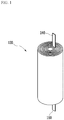
- FIG. 1 is a perspective view of a conventional jelly-roll type of electrode assembly
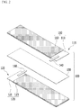
- FIG. 2 is an exploded perspective view of the electrode assembly shown in FIG. 1 before being wound.
- the conventional jelly-roll type of electrode assembly electrode assembly 100 includes a positive electrode 110, a negative electrode 120, and a separator 130, and a separator 130 that is interposed between the positive electrode 110 and the negative electrode 120.
- the positive electrode 110 includes a positive current collector 111 of a sheet shape and a positive active material layer 113 formed on the positive current collector 111.
- the positive current collector 111 includes a positive uncoated region 115 that is a part in which a positive active material layer 113 is not formed.
- the positive uncoated region 115 is disposed on both surfaces of the positive current collector 111.
- a positive tab 140 is attached to the positive uncoated region 115 by welding such that the positive current collector 111 and the positive tab 140 are connected.
- FIG. 3 is a schematic cross-sectional view of a case in which a positive tab is welded to the conventional positive current collector.
- the positive current collector 111 and the positive tab 140 are placed between welding devices 180, and ultrasonic welding or resistance welding is performed. As the welding device 180 damages the active material layer, as shown in FIG. 2 , the positive uncoated region 115 is provided on both surfaces of the positive current collector 111.
- the same or similar structure as the conventional positive electrode 110 is applied so that a negative uncoated region 125 is provided on both surfaces of a negative current collector 121.
- the positive uncoated region 115 and the negative uncoated region 125 provided on both surfaces of the positive current collector 111 and the negative current collector 121 cause the capacity reduction of the electrode assembly 100 by not forming the active material layer in the entire space.
- the number of positive tabs 140 and negative tabs 160 increases, which leads to a further increase in the area of the positive uncoated region 115 and the negative uncoated region 125, thus further reducing the cell capacity.
- Exemplary embodiments of the present invention to solve the above-described problems provide an electrode assembly for a rechargeable battery and a manufacturing method thereof for realizing the cell capacity while obtaining safety against the overcharge by improving a connection structure between the electrode tab and the current collector.
- An electrode assembly includes: an electrode current collector; an uncoated region in which an electrode active material layer is not formed at one surface of the electrode current collector; an electrode tab disposed at the uncoated region; and a conductive adhesive part disposed between the uncoated region and the electrode tab, wherein the conductive adhesive part includes a gas generation material.
- the conductive adhesive part may further include a conductive material and an adhesive material.
- the adhesive material, the conductive material, and the gas generation material may form the conductive adhesive part as a slurry type.
- a gas may be generated such that a volume of the conductive adhesive part may increase.
- the decomposition voltage may be a voltage of 4.5 V or more.
- the gas generation material may include at least one among Li 2 CO 3 , K 2 CO 3 , CaCO 3 , BaCO 3 , and SrCO 3 .
- the thickness of the conductive adhesive part may be 10 micrometers or less.
- the electrode tab may be a metal belt-type member having a width and a length
- the electrode tab may include an electrode tab overlapping part stacked at the uncoated region and an electrode tab extension part extending from the electrode tab overlapping part to the outside of the electrode current collector
- the conductive adhesive part may be formed of the same shape and area as the electrode tab overlapping part.
- An electrode assembly manufacturing method for a rechargeable battery includes: coating a conductive adhesive solution including a gas generation material on a metal plate material for an electrode tab; forming a releasing film on the metal plate material for the electrode tab to cover the coated conductive adhesive solution; drying the conductive adhesive solution to be changed into a conductive adhesive part; a step slitting the metal plate material for the electrode tab to form a plurality of strips; cutting a plurality of strips to manufacture a plurality of electrode tab that the conductive adhesive part and the releasing film are stacked; removing the releasing film from the electrode tab; and adhering the electrode tab from which the releasing film is removed to one surface of the electrode current collector.
- the coating of the conductive adhesive solution may allow a coated region where the conductive adhesive solution is coated in a vertical direction and a non-coated region where the conductive adhesive solution is not coated to be alternately disposed in a horizontal direction.
- the plurality of strips may be cut so that the electrode tab includes one coated region and one non-coated region.
- the electrode tab may include an electrode tab overlapping a part stacked at the electrode current collector and an electrode tab extension part extending from the electrode tab overlapping part to the outside of the electrode current collector, a transverse length of the coated region may be the same as the length of the electrode tab overlapping part, and the transverse length of the non-coated region may be the same as the length of the electrode tab extension part.
- the adhering of the electrode tab to one surface of the electrode current collector may adhere the electrode tab to the uncoated region where the electrode active material layer is not formed among one surface of the electrode current collector.
- the conductive adhesive solution may be manufactured as a slurry type further including a conductive material and an adhesive material.
- the gas generation material When the gas generation material reaches the decomposition voltage, the gas may be generated such that the volume of the conductive adhesive part may increase.
- the decomposition voltage may be a voltage of 4.5 V or more.
- the gas generation material may include at least one among Li 2 CO 3 , K 2 CO 3 , CaCO 3 , BaCO 3 , and SrCO 3 .
- the thickness of the conductive adhesive part may be 10 micrometer or less.
- the manufacturing of the electrode for the rechargeable battery ensuring safety in the abnormal operation state such as an overcharge is possible without increasing the resistance.
- the electrode tab with the conductive adhesive part and the releasing film may be mass produced through a process of slitting and cutting the metal plate material for the electrode tab in which the conductive adhesive part and the releasing film are formed without a separate welding process.
- the phrase “on a plane” means viewing the object portion from the top
- the phrase “on a cross-section” means viewing a cross-section of which the object portion is vertically cut from the side.
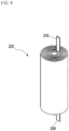
- FIG. 4 is a perspective view of a jelly-roll type electrode assembly according to an exemplary embodiment of the present invention.
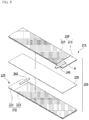
- FIG. 5 is an exploded perspective view of the electrode assembly of FIG. 4 before being wound.
- FIG. 6 is an enlarged top plan view of a portion A of FIG. 5 .
- FIG. 7 is a cross-sectional view taken along a direction V-V' of FIG. 6 .
- FIG. 8 is an enlarged top plan view of a portion C of FIG. 7 .
- FIG. 9 is an enlarged cross-sectional view of a portion C of FIG. 7 after gas generation.
- an electrode assembly 200 includes a pair of electrodes and a separator 230 interposed therebetween.
- the pair of electrodes includes a positive electrode 210 and a negative electrode 220.
- FIG. 5 shows a state before the electrode assembly 200 is wound.
- the positive electrode 210, the separator 230, and the negative electrode 220 are formed in a sheet shape and are sequentially stacked.
- These electrode assemblies 200 are encapsulated and received in an exterior member (not shown) with an electrolyte solution to be manufactured as a rechargeable battery.
- the configuration for the positive electrode 210 and the configuration for the negative electrode 220 are the same as or similar to each other, in FIG. 5 , the description will be made on the basis of the positive electrode 210 among the electrodes.
- the positive electrode 210 includes a sheet-shaped positive current collector 211 and a positive active material layer 213 formed on the positive current collector 211.
- the positive current collector 211 includes a positive uncoated region 215 in which the positive active material layer 213 is not formed.
- the positive active material layer 213 is preferably formed on both surfaces of the positive current collector 211, as shown.
- the positive active material layer 213 is coated on a portion of the positive current collector 211, and as shown in FIG. 5 , as an exemplary embodiment, it may be coated while leaving the area of the rectangle at one end of the length direction of the positive current collector 211.
- the portion where the positive active material layer 213 is not formed corresponds to the positive uncoated region 215.
- the positive uncoated region 215 is formed on only one side of the positive current collector 211, unlike in the conventional art in which it is formed on both surfaces of the positive current collector 211.
- a positive tab 240 is adhered to the positive uncoated region 215, and the positive tab 240 and the positive electrode 210 are electrically connected to each other.
- the positive tab 240 may be bonded to the positive uncoated region 215 by a conductive adhesive part, which will be described later, and this is described with reference to FIG. 7 and the like.
- the positive uncoated region 215 on only one side of the electrode current collector without damaging the positive active material layer 213 by attaching the positive tab 240 through a conductive adhesive part 250 instead of by the conventional welding. Therefore, the area of the positive active material layer 213 may be increased to increase the amount of the active material, thereby increasing of the capacity of the rechargeable battery. Particularly, in the high power model of the battery, since the number of electrode tabs increases, the capacity improvement effect is larger than in the conventional one.
- the position and shape of the positive uncoated region 215 are not limited thereto, and may be modified.
- the positive uncoated region 215 may be formed with the area of the rectangle at one end of the width direction of the positive current collector 211.
- the positive uncoated region 215 may be formed with the area of the rectangle at the center of the positive current collector 211.
- the positive uncoated region 215 is formed to extend from one side of the positive current collector 211 to the other, however the positive uncoated region 215 has a minimum size only in the region overlapping the positive tab 240.
- the negative electrode 220 includes a negative current collector 221 of the sheet shape like the positive electrode 210 mentioned above and a negative active material layer 223 formed on a negative current collector 221, and the negative current collector 221 includes a negative uncoated region 225 in which a negative active material layer 223 is not formed.
- the contents of the positive electrode 210 described above may also be applied to the constituent elements related to the negative electrode 220.
- the positive uncoated region 215 is disposed at one end of the length direction of the positive current collector 211, and the negative uncoated region 225 is disposed at one end of the negative direction of the negative current collector 221, but opposite to the end where the positive uncoated region 215 is disposed.
- the positions of the positive uncoated region 215 and the negative uncoated region 225 are not limited thereto, and may be the same or they may overlap each other.
- the material of the positive current collector 211 aluminum is mainly used.
- the material of the positive current collector 211 may be stainless steel, nickel, titanium, fire carbon, or aluminum, or a surface-treatment of a stainless steel surface with carbon, nickel, titanium, silver, etc. may be provided.
- the material of a positive current collector 211 there is no limit to the material of a positive current collector 211 as long as it is a material with high conductivity and not causing a chemical change of the rechargeable battery.
- the negative current collector 221 a copper material is mainly used.
- the material of the negative current collector 221 may be stainless steel, aluminum, nickel, titanium, sintered carbon, or copper, or a surface treatment of a stainless steel surface with carbon, nickel, titanium, silver, etc. and an aluminum-cadmium alloy may be used.
- the positive active material forming the positive active material layer 213 is a lithium-containing active material, and as a representative example, a metal oxide such as LiCoO 2 , LiNiO 2 , LiMnO 2 , LiMn 2 O 4 , LiFePO 4 , or Li 1+z Ni 1-x-y CO x M y O 2 (0 ⁇ x ⁇ 1, 0 ⁇ y ⁇ 1, 0 ⁇ x+y ⁇ 1, 0 ⁇ z ⁇ 1, M is a metal such as Al, Sr, Mg, La, or Mn) may be used.
- a metal oxide such as LiCoO 2 , LiNiO 2 , LiMnO 2 , LiMn 2 O 4 , LiFePO 4 , or Li 1+z Ni 1-x-y CO x M y O 2 (0 ⁇ x ⁇ 1, 0 ⁇ y ⁇ 1, 0 ⁇ x+y ⁇ 1, 0 ⁇ z ⁇ 1, M is a metal such as Al, Sr, Mg, La, or Mn) may be used.
- the negative active material forming the negative active material layer 223 is a carbon-containing active material, and as the negative active material, a carbon material such as crystalline carbon, amorphous carbon, a carbon composite, carbon fiber, and the like, or a lithium metal, a lithium alloy, or the like may be used.
- the positive active material layer 213 and the negative active material layer 223 may further include a binder and a conductive material in addition to the active material.
- the binder has a function of easily adhering the active material particles to each other and easily adhering the active material to the current collector, and typical examples may include polyvinyl alcohol, carboxylmethyl cellulose, hydroxypropyl cellulose, diacetyl cellulose, polyvinyl chloride, carboxylated polyvinyl chloride, polyvinyl fluoride, a polymer including ethylene oxide, polyvinylpyrrolidone, polyurethane, polytetrafluoroethylene, polyvinylidene fluoride, polyethylene, polypropylene, styrene-butadiene rubber, acrylated styrene-butadiene rubber, epoxy resin, nylon, and the like, however it is not limited thereto.
- the conductive material provides conductivity to the electrode, and may be any electron conductive material that does not cause a chemical change in the battery configuration, and examples may include a carbon-based material such as natural graphite, artificial graphite, carbon black, acetylene black, ketjen black, and carbon fiber, a metal-based material such as a metal powder or a metal fiber of copper, nickel, aluminum, silver, etc., conductive polymers such as a polyphenylene derivative, or a mixture of conductive materials.
- a carbon-based material such as natural graphite, artificial graphite, carbon black, acetylene black, ketjen black, and carbon fiber
- a metal-based material such as a metal powder or a metal fiber of copper, nickel, aluminum, silver, etc.
- conductive polymers such as a polyphenylene derivative, or a mixture of conductive materials.
- the separator 230 is not particularly limited as long as it is a porous material.
- the separator 230 may be made of a polymer layer with a porous, for example, porous polyolefin layer, polyvinylidene fluoride-hexafluoro propylene, polyvinylidene fluoride-trichloroethylene, polymethylmethacrylate, polyacrylonitrile, polyvinylpyrrolidone, polyvinyl acetate, an ethylene vinyl acetate copolymer, polyethylene oxide, cellulose acetate, cellulose acetate butyrate, cellulose acetate propionate, cyanoethyl pullulan, cyanoethyl polyvinyl alcohol, cyanoethyl cellulose, cyanoethyl sucrose, pullulan, carboxyl methyl cellulose, acrylonitrile styrene butadiene copolymer, polyethylene terephthalate, polybutylene terephthalate
- An inorganic particle may be attached to one surface or both surfaces of the separator 230.
- the inorganic particles are preferably inorganic particles having a high dielectric constant of 5 or more, and more preferably inorganic material particles having a dielectric constant of 10 or more and a low density. This is so lithium ions moving in the cell may be easily transferred.
- Non-limiting examples of the inorganic particles having the high dielectric constant of 5 or more include Pb(Zr, Ti)O 3 (PZT), Pb 1-x La x Zr 1-y Ti y O 3 (PLZT), Pb(Mg 3 Nb 2/3 )O 3 -PbTiO 3 (PMN-PT), BaTiO 3 , HfO 2 , SrTiO 3 , TiO 2 , Al 2 O 3 , ZrO 2 , SnO 2 , CeO 2 , MgO, CaO, ZnO, Y 2 O 3 , or mixtures thereof.
- the positive tab 240 may be a metal belt-type member having a predetermined width and length.
- the positive tab 240 overlaps the positive uncoated region 215 of the positive current collector 211 to be electrically connected thereto.
- the positive tab 240 includes a positive tab overlapping part 241 stacked on the positive current collector 211, and a positive tab extension part 242 protruded and extended from one end of the positive current collector 211 to the outside in the positive tab overlapping part 241.
- the positive tab overlapping part 241 is fixed to the positive uncoated region 215 of the positive current collector 211.
- the positive electrode 210 to which the positive tab 240 is fixed is sequentially stacked and wound with the separator 230 and the negative electrode 220, so that the positive tab overlapping part 241 overlaps the positive electrode 210 and the separator 230.
- the positive tab 240 is attached to the positive uncoated region 215 of the positive current collector 211 through the conductive adhesive part 250 rather than the welding. Therefore, the positive electrode 210 and the positive tab 240 are electrically connected.
- the conductive adhesive part 250 has adhesive, thereby fixing the positive tab 240 to the positive current collector 211.
- the conductive adhesive part 250 may be formed in the same shape and area as the positive tab overlapping part 241. It is necessary to derive the length or area of the conductive adhesive part 250 that satisfies the minimum required adhesive. However, in the case of the high power model, the temperature may be locally raised due to a current concentration when the area of the positive tab overlapping part 241 is narrow. Therefore, the conductive adhesive part 250 may be formed to have an area which is the same as the entire area of the positive tab overlapping part 241 touched the positive current collector 211.
- the conductive adhesive part 250 includes an adhesive material 251, a conductive material 252, and a gas generation material 253.
- the adhesive material 251 should not react with the electrolyte solution, and for example, acrylate series are preferable.
- acrylate series are preferable.
- the positive tab 240 may be be formed of the same kind of metal material as the positive current collector 211.
- it may be aluminum.
- the conductive material 252 of the conductive adhesive part 250 in the positive electrode 210 is preferably one of aluminum particles, carbon nanotubes (CNT), and carbon black. Particularly, it is preferably aluminum particles.
- CNT carbon nanotubes
- a path of the current based on the aluminum material may be provided between the positive tab 240 - the conductive adhesive part 250 - the positive current collector 211 without increasing the contact resistance.
- the aluminum particles may be spherical-shaped particles.
- a negative tab 260 may have the same kind of metal material as the negative current collector 221.
- it may be copper.
- the conductive material (not shown) of the conductive adhesive part in the negative electrode 220 is preferably one of CNT, carbon black, and copper particles. Particularly, copper particles are preferable.
- the path of the current based on the copper material may be provided between the negative tab 260 - the conductive adhesive part (not shown) - the negative current collector 221 without increasing the contact resistance.
- the conductive adhesive part 250 has conductivity at a level at which the resistance is not significantly increased compared with the case where the gas generation material 253 is not included due to the electrical passage of the conductive material 252 having low resistance.
- the gas generation material 253 is composed of a material which is decomposed when a predetermined voltage is reached to generate a gas.
- the predetermined voltage may be defined as a decomposition voltage for decomposing the gas generation material 253 to generate a gas, and has a different value depending on the type of the gas generation material 253.
- the conductive adhesive part 250 before reaching the decomposition voltage has a first thickness X, but when the decomposition voltage is reached due to the abnormal operating state and then the gas is generated by the gas generation material 253, the volume of the conductive adhesive part 250 increases due to the generated gas such that the thickness of the conductive adhesive part 250 may become a second thickness Y that is larger than the first thickness X.
- a flow of the conductive material 252 occurs and the distance between the conductive materials 252 increases. Since the distance between the conductive material 252 increases, the resistance of the conductive adhesive part 250 increases sharply which causes an increase in the resistance and an increase in the voltage of the battery cell, thereby reaching a finish voltage.
- the gas generating substance 253 is not particularly limited as long as it is a substance which generates gas upon reaching a predetermined voltage.
- it may be a Li 2 CO 3 , K 2 CO 3 , CaCO 3 , BaCO 3 , or SrCO 3 material.
- Li 2 CO 3 is preferable. If Li 2 CO 3 is used as the gas generation material 253 and the voltage applied in the electrode assembly 200 is 4.7-4.85 V or more, Li 2 CO 3 is decomposed such that CO and CO 2 gas is produced. The volume of the conductive adhesive part 250 is increased by the generated CO and CO 2 gas.
- the decomposition voltage may vary slightly depending on the type of gas generation material 253, but according to the present exemplary embodiment, by considering the decomposition voltage of Li 2 CO 3 (4.7 V or more), K 2 CO 3 (4.5 V or more), CaCO 3 (4.8 V or more), BaCO 3 (4.9 V or more), and SrCO 3 (4.9 V or more), it is preferable that the decomposition voltage is 4.5 V or more.
- the conductive adhesive part 250 including the adhesive material 251, the conductive material 252, and the gas generation material 253 may be in a form that is coated as a slurry type between the electrode current collector and the electrode tab. Since the conductive adhesive part 250 is in the slurry form, the thickness of the conductive adhesive part 250 may be more easily adjusted or the content of the gas generation material 253 in the conductive adhesive part 250 may be adjusted.
- the amount of gas generated at a predetermined voltage in the abnormal operating state increases, and then the end voltage may be reached more quickly, but simultaneously the gas acts as a resistance in the battery such that the performance of the battery may be deteriorated. It is necessary to adjust a quantum appropriately according to a field in which the battery is used.
- the resistance of the conductive adhesive part 250 can be freely adjusted for each manufactured battery, thereby reducing the manufacturing cost of the battery, without any additional process, and the degree of the reaching voltage for the overcharge or the overdischarge and the resistance of the conductive adhesive part 250 may be freely adjusted for each manufactured battery, thereby reducing a cost of the battery manufacturing.
- the adhesive material 251, the conductive material 252, and the gas generation material 253 are dispersed without being concentrated in a specific part, thereby effectively securing electrical conductivity, an adhesion degree, and the reaching degree of the end voltage.
- the weight ratio of the adhesive material 251 is fixed at 40 %, the weight ratio of the conductive material 252 to be 30 % to 50 %, and the weight ratio of the gas generation material 253 to be 10 % to 30 %.
- the thickness of the conductive adhesive part 250 is preferably less than 10 micrometers.
- the uncoated region in which the active material layer is not coated is provided on both surfaces of the electrode current collector and the tab is welding-bonded to the uncoated region, however in an exemplary embodiment of the present invention, since the adhering is performed through the conductive adhesive part 250 that is not welding, as shown in FIG. 5 and FIG. 7 , the positive uncoated region 215 may be formed on the other surface of the positive current collector 211 to form the positive tab 240 even in the state that the positive active material layer 213 is completely coated on one surface of the positive current collector 211. Therefore, since the uncoated region is not formed on the surface opposite to the surface to which the positive tab 240 is adhered, the sufficient capacity may be secured. Since the structure for the positive electrode 210 and the structure for the negative electrode 220 are the same as or similar to each other, it is possible to secure the battery capacity even in the case of the negative electrode 220.
- the gas generation material is placed in the electrode layer containing the active material for the purpose of assuring the stability of the overcharge, the external short circuit, an acicular penetration, the local damage, etc., the amount of the active material is reduced by the space occupied by the gas generation material and the battery capacity is reduced, however, according to an exemplary embodiment of the present invention, the battery generation deterioration due to active material reduction is minimized by placing the gas generation material in the conductive adhesive part 250 between the electrode current collectors 211 and 221 and the electrode tabs 240 and 260.
- FIG. 10 is a perspective view of an electrode tab according to an exemplary embodiment of the present invention.
- the electrode tab 360 of FIG. 10 may be used in the manufacturing of the electrode assembly 200 as the above-described positive tab 240 or negative tab 260.
- the electrode tab 360 is electrically connected to the electrode current collector, and is a metal belt type of member having a width and a length.
- the electrode tab 360 includes an electrode tab overlapping part 361 stacked at the electrode current collector, and an electrode tab extension part 362 extending from the electrode tab overlapping part 361 outside the electrode current collector.
- a conductive adhesive part 370 and a releasing film 380 are stacked at the electrode tab overlapping part 361 with the same shape and area as the electrode tab overlapping part 361.
- FIG. 11 and FIG. 12 are views to explain an electrode assembly manufacturing method according to the present invention.
- the adhesive material, the conductive material, and the gas generation material are mixed to manufacture the conductive adhesive solution of the slurry form.
- the adhesive material should not react with the electrolyte solution as described above, and for example, acrylate series are preferable.
- the gas generating material is not particularly limited as long as it is a material that generates gas when a predetermined voltage is reached, and for example, Li 2 CO 3 , K 2 CO 3 , CaCO 3 , BaCO 3 , or SrCO 3 materials may be used. Particularly, Li 2 CO 3 is preferable.
- the conductive adhesive solution is coated on a metal plate material 359 for the tab.
- a coated region 374 where the conductive adhesive solution is coated in the vertical direction and a non-coated region 376 where the conductive adhesive solution is not coated are alternately formed according to the horizontal direction.
- a transverse length a of the coated region 374 is the same as the length of the electrode tab overlapping part 361 of FIG. 10
- a transverse length b of the non-coated region 376 is the same as the length of the electrode tab extension part 362 of FIG. 10 .
- the coated region 374 is formed in the stripe pattern rather than on the entire surface of the metal plate material 359 for the tab. This forming method may be performed by using slot die coating similar to that used for coating the electrode active material layer, or by placing a barrier layer such as a bar on the non-coated region 376 and sprinkling the conductive adhesive solution thereon.
- a releasing film covering the coated region 374 and the non-coated region 376 is stacked on the metal plate material 359 for the tab.
- the conductive adhesive solution of the coated region 374 is dried to be converted into a conductive adhesive part 370.
- the metal plate material 359 for the tab of FIG. 11 is slit into a plurality of strips 359' along the vertical direction.
- any one strip 359' when the strip 359' is cut so that one coated region 374 and one non-coated region 376 are included, the plurality of electrode tabs 360 of which the conductive adhesive part 370 and the releasing film 380 are stacked at the electrode tab overlapping part 361 with the same shape and area as the electrode tab overlapping part 361 may be obtained like in FIG. 10 .
- the electrode tab 360 may be adhered to the electrode current collector to manufacture the electrode assembly without troublesome welding through a series of processes by removing the releasing film 380 so that the conductive adhesive part 370 is placed at the positive uncoated region 215 and/or the negative uncoated region 225.
- the electrode tabs according to the present invention may be used to manufacture of the electrode assembly and the rechargeable battery including the same by replacing the electrode tab of the conventional welding method.
- the electrode tab according to the present invention is manufactured as the adhesive tab to manufacture the rechargeable battery by omitting the conventional complicated welding process through the simple operation of stripping the releasing film and bonding the electrode tab to the electrode current collector.
- an ultrasonic welding process is performed separately, there is a problem that efficiency is deteriorated because an equipment cost and maintenance cost related to the welding are incurred.
- this problem is solved by using the electrode tab having the release film attached thereto.
- the electrode assembly of the present invention which is capable of being manufactured through this method, may allow the connection of the electrode tab and the electrode current collector without damaging the active material layer.
- the uncoated region is formed only on one surface of the current collector, thus leading to the increase of the capacity of the rechargeable battery. Also, by disposing the gas generation material for safety ensuring at the conductive adhesive part between the electrode current collector and the electrode tab, not in the electrode layer, the battery efficiency deterioration may be minimized due to the active material reduction.
- the rechargeable battery for minimizing the limitation of the battery capacity may be manufactured while ensuring the safety for the abnormal operation state such as the overcharge, the external short, and the like.
- the abnormal operation state such as the overcharge, the external short, and the like.
Landscapes
- Chemical & Material Sciences (AREA)
- Chemical Kinetics & Catalysis (AREA)
- Electrochemistry (AREA)
- General Chemical & Material Sciences (AREA)
- Engineering & Computer Science (AREA)
- Manufacturing & Machinery (AREA)
- Connection Of Batteries Or Terminals (AREA)
- Battery Electrode And Active Subsutance (AREA)
Abstract
Description
- This application claims priority to and the benefit of Korean Patent Application No.
10-2018-0071080 - The present invention relates to a rechargeable battery and a manufacturing method thereof, and further relates to an electrode assembly having an improved electrode tab and a current collector connection structure, and a manufacturing method thereof.
- In recent years, as a demand for portable electronic devices such as a laptop, a video camera, and a portable phone has increased sharply and development of electric vehicles, energy storage batteries, robots, and satellites has become full-scale, many studies for a rechargeable battery used as a driving power source thereof have been undertaken.
- Examples of such rechargeable batteries include a nickel cadmium battery, a nickel hydrogen battery, a nickel zinc battery, and a lithium secondary battery. Among them, since the lithium rechargeable battery has less of a memory effect than the rechargeable battery of the nickel type, it is widely used in high-tech electronic devices due to a free charging and discharging, a very low self-discharge rate, a high operating voltage, and high energy density per unit weight.
- However, the lithium rechargeable battery is exposed to a high temperature, or when a large current flows in a short time due to an overcharge, an external short circuit, a puncture, local damage, etc., there is a risk of the battery being heated by IR heat and occurrence of an explosion. That is, when the pressure or temperature of the battery rises, a decomposition reaction of an active material and many side reactions proceed, thereby rapidly raising the temperature of the battery, which further accelerates the reaction between the electrolyte and the electrode. Eventually, a thermal runaway phenomenon occurs in which the temperature of the battery rises sharply, and when the temperature rises to a certain level, ignition of the battery may occur, and the lithium rechargeable battery explosion occurs due to the increased internal pressure of the battery.
- Therefore, various methods are being discussed to effectively control the lithium rechargeable battery when it is placed in an abnormal operating state such as an overcurrent state or a high temperature state. As a part of efforts to ensure safety, there is a method of mounting a device outside the cell and a method of using the material inside the cell. PTC and CID devices, using the temperature change, protection circuits controlling the voltage and the current, and safety vents using the change in the internal pressure of the battery correspond to the former, and the latter is the addition of materials that can be changed physically, chemically, or electrochemically according to the changes in the temperature, the voltage, and the current inside the battery.
- In the case of using the material inside the cell, there is a merit that it is possible to apply it to all kinds of the batteries without requiring an additional installation process, however since there are problems that the performance of the battery such as a rate characteristic or capacity of the battery is deteriorated due to the addition of the material and operation with reliability is not provided, a variety of measures that can bring about a definite current blocking effect while minimizing battery performance degradation are being discussed.
- Lithium rechargeable batteries mainly use a lithium oxide and a carbon material as a positive active material and a negative active material, respectively. A positive electrode and a negative electrode in which the positive active material and the negative active material are respectively coated on the current collectors are disposed via a separator interposed therebetween to configure an electrode assembly, and the electrode assembly is received and sealed with an electrolyte solution together in an exterior member.
-
FIG. 1 is a perspective view of a conventional jelly-roll type of electrode assembly, andFIG. 2 is an exploded perspective view of the electrode assembly shown inFIG. 1 before being wound. - Referring to
FIG. 1 andFIG. 2 , the conventional jelly-roll type of electrodeassembly electrode assembly 100 includes apositive electrode 110, anegative electrode 120, and aseparator 130, and aseparator 130 that is interposed between thepositive electrode 110 and thenegative electrode 120. - The
positive electrode 110 includes a positivecurrent collector 111 of a sheet shape and a positiveactive material layer 113 formed on the positivecurrent collector 111. The positivecurrent collector 111 includes a positiveuncoated region 115 that is a part in which a positiveactive material layer 113 is not formed. The positiveuncoated region 115 is disposed on both surfaces of the positivecurrent collector 111. - A
positive tab 140 is attached to the positiveuncoated region 115 by welding such that the positivecurrent collector 111 and thepositive tab 140 are connected. -
FIG. 3 is a schematic cross-sectional view of a case in which a positive tab is welded to the conventional positive current collector. - Referring to
FIG. 3 , the positivecurrent collector 111 and thepositive tab 140 are placed betweenwelding devices 180, and ultrasonic welding or resistance welding is performed. As thewelding device 180 damages the active material layer, as shown inFIG. 2 , the positiveuncoated region 115 is provided on both surfaces of the positivecurrent collector 111. - In the conventional
negative electrode 120, the same or similar structure as the conventionalpositive electrode 110 is applied so that a negativeuncoated region 125 is provided on both surfaces of a negativecurrent collector 121. - The positive
uncoated region 115 and the negativeuncoated region 125 provided on both surfaces of the positivecurrent collector 111 and the negativecurrent collector 121 cause the capacity reduction of theelectrode assembly 100 by not forming the active material layer in the entire space. In a high output model, the number ofpositive tabs 140 andnegative tabs 160 increases, which leads to a further increase in the area of the positiveuncoated region 115 and the negativeuncoated region 125, thus further reducing the cell capacity. - Therefore, it is required to study a lithium rechargeable battery which prevents the risk of danger such as explosion on the overcharge of the lithium rechargeable battery and simultaneously minimizes the capacity deterioration of the battery in order to meet the trend of high-capacity and slimming at the same time.
- Exemplary embodiments of the present invention to solve the above-described problems provide an electrode assembly for a rechargeable battery and a manufacturing method thereof for realizing the cell capacity while obtaining safety against the overcharge by improving a connection structure between the electrode tab and the current collector.
- An electrode assembly according to an exemplary embodiment of the present invention includes: an electrode current collector; an uncoated region in which an electrode active material layer is not formed at one surface of the electrode current collector; an electrode tab disposed at the uncoated region; and a conductive adhesive part disposed between the uncoated region and the electrode tab, wherein the conductive adhesive part includes a gas generation material.
- The conductive adhesive part may further include a conductive material and an adhesive material.
- The adhesive material, the conductive material, and the gas generation material may form the conductive adhesive part as a slurry type.
- When the gas generation material reaches a decomposition voltage, a gas may be generated such that a volume of the conductive adhesive part may increase.
- The decomposition voltage may be a voltage of 4.5 V or more.
- The gas generation material may include at least one among Li2CO3, K2CO3, CaCO3, BaCO3, and SrCO3.
- The thickness of the conductive adhesive part may be 10 micrometers or less.
- In an exemplary embodiment, the electrode tab may be a metal belt-type member having a width and a length, the electrode tab may include an electrode tab overlapping part stacked at the uncoated region and an electrode tab extension part extending from the electrode tab overlapping part to the outside of the electrode current collector, and the conductive adhesive part may be formed of the same shape and area as the electrode tab overlapping part.
- An electrode assembly manufacturing method for a rechargeable battery according to another exemplary embodiment of the present invention includes: coating a conductive adhesive solution including a gas generation material on a metal plate material for an electrode tab; forming a releasing film on the metal plate material for the electrode tab to cover the coated conductive adhesive solution; drying the conductive adhesive solution to be changed into a conductive adhesive part; a step slitting the metal plate material for the electrode tab to form a plurality of strips; cutting a plurality of strips to manufacture a plurality of electrode tab that the conductive adhesive part and the releasing film are stacked; removing the releasing film from the electrode tab; and adhering the electrode tab from which the releasing film is removed to one surface of the electrode current collector.
- The coating of the conductive adhesive solution may allow a coated region where the conductive adhesive solution is coated in a vertical direction and a non-coated region where the conductive adhesive solution is not coated to be alternately disposed in a horizontal direction.
- The plurality of strips may be cut so that the electrode tab includes one coated region and one non-coated region.
- The electrode tab may include an electrode tab overlapping a part stacked at the electrode current collector and an electrode tab extension part extending from the electrode tab overlapping part to the outside of the electrode current collector, a transverse length of the coated region may be the same as the length of the electrode tab overlapping part, and the transverse length of the non-coated region may be the same as the length of the electrode tab extension part.
- The adhering of the electrode tab to one surface of the electrode current collector may adhere the electrode tab to the uncoated region where the electrode active material layer is not formed among one surface of the electrode current collector.
- The conductive adhesive solution may be manufactured as a slurry type further including a conductive material and an adhesive material.
- When the gas generation material reaches the decomposition voltage, the gas may be generated such that the volume of the conductive adhesive part may increase.
- The decomposition voltage may be a voltage of 4.5 V or more.
- The gas generation material may include at least one among Li2CO3, K2CO3, CaCO3, BaCO3, and SrCO3.
- The thickness of the conductive adhesive part may be 10 micrometer or less.
- According to exemplary embodiments of the present invention, by including the gas generation material in the conductive adhesive part between the electrode tab and the electrode current collector, the manufacturing of the electrode for the rechargeable battery ensuring safety in the abnormal operation state such as an overcharge is possible without increasing the resistance.
- Also, the electrode tab with the conductive adhesive part and the releasing film may be mass produced through a process of slitting and cutting the metal plate material for the electrode tab in which the conductive adhesive part and the releasing film are formed without a separate welding process.
-
-
FIG. 1 is a perspective view of a conventional jelly-roll type of electrode assembly. -
FIG. 2 is an exploded perspective view of the electrode assembly ofFIG. 1 before being wound. -
FIG. 3 is a schematic cross-sectional view when a positive tab is welded to a conventional positive current collector. -
FIG. 4 is a perspective view of a jelly-roll type of electrode assembly according to an exemplary embodiment of the present invention. -
FIG. 5 is an exploded perspective view of the electrode assembly ofFIG. 4 before being wound. -
FIG. 6 is an enlarged top plan view of a portion A ofFIG. 5 . -
FIG. 7 is a cross-sectional view taken along a direction V-V' ofFIG. 6 . -
FIG. 8 is an enlarged top plan view of a portion C ofFIG. 7 . -
FIG. 9 is an enlarged cross-sectional view of a portion C ofFIG. 7 after gas generation. -
FIG. 10 is a perspective view of an electrode tab according to an exemplary embodiment of the present invention. -
FIG. 11 andFIG. 12 are views to explain an electrode assembly manufacturing method according to an exemplary embodiment of the present invention. - Hereinafter, various exemplary embodiments of the present invention will be described in detail with reference to accompanying drawings so that those skilled in the art can easily carry out the present invention. As those skilled in the art would realize, the described embodiments may be modified in various different ways, all without departing from the spirit or scope of the present invention.
- For clarity of description of the present invention, parts unrelated to the description are omitted, and the same reference numbers will be used throughout this specification to refer to the same or like parts.
- In addition, the size and thickness of each configuration shown in the drawings are arbitrarily shown for better understanding and ease of description, but the present invention is not limited thereto. In the drawings, the thickness of layers, films, panels, regions, etc., are exaggerated for clarity. In the drawings, for better understanding and ease of description, the thicknesses of some layers and areas are exaggerated.
- It will be understood that when an element such as a layer, film, region, or substrate is referred to as being "on" another element, it can be directly on the other element or intervening elements may also be present. In contrast, when an element is referred to as being "directly on" another element, there are no intervening elements present. Further, in the specification, the word "on" or "above" means positioned on or below the object portion, and does not necessarily mean positioned on the upper side of the object portion based on a gravitational direction.
- In addition, unless explicitly described to the contrary, the word "comprise" and variations such as "comprises" or "comprising" will be understood to imply the inclusion of stated elements but not the exclusion of any other elements.
- Further, in the specification, the phrase "on a plane" means viewing the object portion from the top, and the phrase "on a cross-section" means viewing a cross-section of which the object portion is vertically cut from the side.
-
FIG. 4 is a perspective view of a jelly-roll type electrode assembly according to an exemplary embodiment of the present invention.FIG. 5 is an exploded perspective view of the electrode assembly ofFIG. 4 before being wound.FIG. 6 is an enlarged top plan view of a portion A ofFIG. 5 .FIG. 7 is a cross-sectional view taken along a direction V-V' ofFIG. 6 .FIG. 8 is an enlarged top plan view of a portion C ofFIG. 7 .FIG. 9 is an enlarged cross-sectional view of a portion C ofFIG. 7 after gas generation. - Referring to
FIG. 4 andFIG. 5 , anelectrode assembly 200 according to the present exemplary embodiment includes a pair of electrodes and aseparator 230 interposed therebetween. The pair of electrodes includes apositive electrode 210 and anegative electrode 220. For convenience of explanation,FIG. 5 shows a state before theelectrode assembly 200 is wound. Referring toFIG. 5 , thepositive electrode 210, theseparator 230, and thenegative electrode 220 are formed in a sheet shape and are sequentially stacked. Theseelectrode assemblies 200 are encapsulated and received in an exterior member (not shown) with an electrolyte solution to be manufactured as a rechargeable battery. - Since the configuration for the
positive electrode 210 and the configuration for thenegative electrode 220 are the same as or similar to each other, inFIG. 5 , the description will be made on the basis of thepositive electrode 210 among the electrodes. - Referring to
FIG. 5 , thepositive electrode 210 includes a sheet-shaped positivecurrent collector 211 and a positiveactive material layer 213 formed on the positivecurrent collector 211. The positivecurrent collector 211 includes a positiveuncoated region 215 in which the positiveactive material layer 213 is not formed. The positiveactive material layer 213 is preferably formed on both surfaces of the positivecurrent collector 211, as shown. The positiveactive material layer 213 is coated on a portion of the positivecurrent collector 211, and as shown inFIG. 5 , as an exemplary embodiment, it may be coated while leaving the area of the rectangle at one end of the length direction of the positivecurrent collector 211. The portion where the positiveactive material layer 213 is not formed corresponds to the positiveuncoated region 215. The positiveuncoated region 215 according to the present exemplary embodiment is formed on only one side of the positivecurrent collector 211, unlike in the conventional art in which it is formed on both surfaces of the positivecurrent collector 211. Apositive tab 240 is adhered to the positiveuncoated region 215, and thepositive tab 240 and thepositive electrode 210 are electrically connected to each other. In the present exemplary embodiment, thepositive tab 240 may be bonded to the positiveuncoated region 215 by a conductive adhesive part, which will be described later, and this is described with reference toFIG. 7 and the like. - It is possible to form the positive
uncoated region 215 on only one side of the electrode current collector without damaging the positiveactive material layer 213 by attaching thepositive tab 240 through a conductiveadhesive part 250 instead of by the conventional welding. Therefore, the area of the positiveactive material layer 213 may be increased to increase the amount of the active material, thereby increasing of the capacity of the rechargeable battery. Particularly, in the high power model of the battery, since the number of electrode tabs increases, the capacity improvement effect is larger than in the conventional one. - However, the position and shape of the positive
uncoated region 215 are not limited thereto, and may be modified. For example, the positiveuncoated region 215 may be formed with the area of the rectangle at one end of the width direction of the positivecurrent collector 211. Also, the positiveuncoated region 215 may be formed with the area of the rectangle at the center of the positivecurrent collector 211. In addition, in the present exemplary embodiment, the positiveuncoated region 215 is formed to extend from one side of the positivecurrent collector 211 to the other, however the positiveuncoated region 215 has a minimum size only in the region overlapping thepositive tab 240. Thenegative electrode 220 includes a negativecurrent collector 221 of the sheet shape like thepositive electrode 210 mentioned above and a negativeactive material layer 223 formed on a negativecurrent collector 221, and the negativecurrent collector 221 includes a negativeuncoated region 225 in which a negativeactive material layer 223 is not formed. The contents of thepositive electrode 210 described above may also be applied to the constituent elements related to thenegative electrode 220. - Referring to
FIG. 5 , the positiveuncoated region 215 is disposed at one end of the length direction of the positivecurrent collector 211, and the negativeuncoated region 225 is disposed at one end of the negative direction of the negativecurrent collector 221, but opposite to the end where the positiveuncoated region 215 is disposed. However, the positions of the positiveuncoated region 215 and the negativeuncoated region 225 are not limited thereto, and may be the same or they may overlap each other. - As the material of the positive
current collector 211, aluminum is mainly used. In addition, the material of the positivecurrent collector 211 may be stainless steel, nickel, titanium, fire carbon, or aluminum, or a surface-treatment of a stainless steel surface with carbon, nickel, titanium, silver, etc. may be provided. Furthermore, there is no limit to the material of a positivecurrent collector 211 as long as it is a material with high conductivity and not causing a chemical change of the rechargeable battery. - As the negative
current collector 221, a copper material is mainly used. In addition, the material of the negativecurrent collector 221 may be stainless steel, aluminum, nickel, titanium, sintered carbon, or copper, or a surface treatment of a stainless steel surface with carbon, nickel, titanium, silver, etc. and an aluminum-cadmium alloy may be used. - The positive active material forming the positive
active material layer 213 is a lithium-containing active material, and as a representative example, a metal oxide such as LiCoO2, LiNiO2, LiMnO2, LiMn2O4, LiFePO4, or Li1+zNi1-x-yCOxMyO2 (0≤x≤1, 0≤y≤1, 0≤x+y≤1, 0≤z≤1, M is a metal such as Al, Sr, Mg, La, or Mn) may be used. The negative active material forming the negativeactive material layer 223 is a carbon-containing active material, and as the negative active material, a carbon material such as crystalline carbon, amorphous carbon, a carbon composite, carbon fiber, and the like, or a lithium metal, a lithium alloy, or the like may be used. - The positive
active material layer 213 and the negativeactive material layer 223 may further include a binder and a conductive material in addition to the active material. The binder has a function of easily adhering the active material particles to each other and easily adhering the active material to the current collector, and typical examples may include polyvinyl alcohol, carboxylmethyl cellulose, hydroxypropyl cellulose, diacetyl cellulose, polyvinyl chloride, carboxylated polyvinyl chloride, polyvinyl fluoride, a polymer including ethylene oxide, polyvinylpyrrolidone, polyurethane, polytetrafluoroethylene, polyvinylidene fluoride, polyethylene, polypropylene, styrene-butadiene rubber, acrylated styrene-butadiene rubber, epoxy resin, nylon, and the like, however it is not limited thereto. The conductive material provides conductivity to the electrode, and may be any electron conductive material that does not cause a chemical change in the battery configuration, and examples may include a carbon-based material such as natural graphite, artificial graphite, carbon black, acetylene black, ketjen black, and carbon fiber, a metal-based material such as a metal powder or a metal fiber of copper, nickel, aluminum, silver, etc., conductive polymers such as a polyphenylene derivative, or a mixture of conductive materials. - The
separator 230 is not particularly limited as long as it is a porous material. Theseparator 230 may be made of a polymer layer with a porous, for example, porous polyolefin layer, polyvinylidene fluoride-hexafluoro propylene, polyvinylidene fluoride-trichloroethylene, polymethylmethacrylate, polyacrylonitrile, polyvinylpyrrolidone, polyvinyl acetate, an ethylene vinyl acetate copolymer, polyethylene oxide, cellulose acetate, cellulose acetate butyrate, cellulose acetate propionate, cyanoethyl pullulan, cyanoethyl polyvinyl alcohol, cyanoethyl cellulose, cyanoethyl sucrose, pullulan, carboxyl methyl cellulose, acrylonitrile styrene butadiene copolymer, polyethylene terephthalate, polybutylene terephthalate, polyester, polyacetal, polyamide, polyetheretherketone, polyethersulfone, polyphenylene oxide, polyphenylene sulfide, polyethylene naphthalene, non-woven fabric layer, a layer with a porous web structure, or mixtures thereof. - An inorganic particle may be attached to one surface or both surfaces of the
separator 230. The inorganic particles are preferably inorganic particles having a high dielectric constant of 5 or more, and more preferably inorganic material particles having a dielectric constant of 10 or more and a low density. This is so lithium ions moving in the cell may be easily transferred. Non-limiting examples of the inorganic particles having the high dielectric constant of 5 or more include Pb(Zr, Ti)O3 (PZT), Pb1-xLaxZr1-yTiyO3 (PLZT), Pb(Mg3Nb2/3)O3-PbTiO3 (PMN-PT), BaTiO3, HfO2, SrTiO3, TiO2, Al2O3, ZrO2, SnO2, CeO2, MgO, CaO, ZnO, Y2O3, or mixtures thereof. - Referring to
FIG. 5 andFIG. 6 , thepositive tab 240 may be a metal belt-type member having a predetermined width and length. Thepositive tab 240 overlaps the positiveuncoated region 215 of the positivecurrent collector 211 to be electrically connected thereto. Specifically, thepositive tab 240 includes a positivetab overlapping part 241 stacked on the positivecurrent collector 211, and a positivetab extension part 242 protruded and extended from one end of the positivecurrent collector 211 to the outside in the positivetab overlapping part 241. - The positive
tab overlapping part 241 is fixed to the positiveuncoated region 215 of the positivecurrent collector 211. Thepositive electrode 210 to which thepositive tab 240 is fixed is sequentially stacked and wound with theseparator 230 and thenegative electrode 220, so that the positivetab overlapping part 241 overlaps thepositive electrode 210 and theseparator 230. - As shown in
FIG. 7 , thepositive tab 240 is attached to the positiveuncoated region 215 of the positivecurrent collector 211 through the conductiveadhesive part 250 rather than the welding. Therefore, thepositive electrode 210 and thepositive tab 240 are electrically connected. The conductiveadhesive part 250 has adhesive, thereby fixing thepositive tab 240 to the positivecurrent collector 211. - In particular, the conductive
adhesive part 250 may be formed in the same shape and area as the positivetab overlapping part 241. It is necessary to derive the length or area of the conductiveadhesive part 250 that satisfies the minimum required adhesive. However, in the case of the high power model, the temperature may be locally raised due to a current concentration when the area of the positivetab overlapping part 241 is narrow. Therefore, the conductiveadhesive part 250 may be formed to have an area which is the same as the entire area of the positivetab overlapping part 241 touched the positivecurrent collector 211. - Referring to
FIG. 8 , the conductiveadhesive part 250 includes anadhesive material 251, aconductive material 252, and agas generation material 253. Theadhesive material 251 should not react with the electrolyte solution, and for example, acrylate series are preferable. In theadhesive material 251, it may be that butyl acrylate/4-hydroxybutyl acrylate = 98:2 or ethyl hexyl acrylate/acrylic acid = 98:2. - The
positive tab 240 may be be formed of the same kind of metal material as the positivecurrent collector 211. For example, it may be aluminum. In such a case, theconductive material 252 of the conductiveadhesive part 250 in thepositive electrode 210 is preferably one of aluminum particles, carbon nanotubes (CNT), and carbon black. Particularly, it is preferably aluminum particles. Thus, a path of the current based on the aluminum material may be provided between the positive tab 240 - the conductive adhesive part 250 - the positivecurrent collector 211 without increasing the contact resistance. The aluminum particles may be spherical-shaped particles. - A
negative tab 260 may have the same kind of metal material as the negativecurrent collector 221. For example, it may be copper. In such a case, the conductive material (not shown) of the conductive adhesive part in thenegative electrode 220 is preferably one of CNT, carbon black, and copper particles. Particularly, copper particles are preferable. Thus, the path of the current based on the copper material may be provided between the negative tab 260 - the conductive adhesive part (not shown) - the negativecurrent collector 221 without increasing the contact resistance. - In the normal operating state of the rechargeable battery, the conductive
adhesive part 250 has conductivity at a level at which the resistance is not significantly increased compared with the case where thegas generation material 253 is not included due to the electrical passage of theconductive material 252 having low resistance. - The
gas generation material 253 is composed of a material which is decomposed when a predetermined voltage is reached to generate a gas. Herein, the predetermined voltage may be defined as a decomposition voltage for decomposing thegas generation material 253 to generate a gas, and has a different value depending on the type of thegas generation material 253. - As shown in
FIG. 8 andFIG. 9 , the conductiveadhesive part 250 before reaching the decomposition voltage has a first thickness X, but when the decomposition voltage is reached due to the abnormal operating state and then the gas is generated by thegas generation material 253, the volume of the conductiveadhesive part 250 increases due to the generated gas such that the thickness of the conductiveadhesive part 250 may become a second thickness Y that is larger than the first thickness X. Depending on the increased volume of the conductiveadhesive part 250, a flow of theconductive material 252 occurs and the distance between theconductive materials 252 increases. Since the distance between theconductive material 252 increases, the resistance of the conductiveadhesive part 250 increases sharply which causes an increase in the resistance and an increase in the voltage of the battery cell, thereby reaching a finish voltage. Through the above process, the abnormal operation state such as the overcharge or the overdischarge is terminated, and the stability of the secondary battery may be ensured. - The
gas generating substance 253 is not particularly limited as long as it is a substance which generates gas upon reaching a predetermined voltage. For example, it may be a Li2CO3, K2CO3, CaCO3, BaCO3, or SrCO3 material. Particularly, Li2CO3 is preferable. If Li2CO3 is used as thegas generation material 253 and the voltage applied in theelectrode assembly 200 is 4.7-4.85 V or more, Li2CO3 is decomposed such that CO and CO2 gas is produced. The volume of the conductiveadhesive part 250 is increased by the generated CO and CO2 gas. The decomposition voltage may vary slightly depending on the type ofgas generation material 253, but according to the present exemplary embodiment, by considering the decomposition voltage of Li2CO3 (4.7 V or more), K2CO3 (4.5 V or more), CaCO3 (4.8 V or more), BaCO3 (4.9 V or more), and SrCO3 (4.9 V or more), it is preferable that the decomposition voltage is 4.5 V or more. - The conductive
adhesive part 250 including theadhesive material 251, theconductive material 252, and thegas generation material 253 may be in a form that is coated as a slurry type between the electrode current collector and the electrode tab. Since the conductiveadhesive part 250 is in the slurry form, the thickness of the conductiveadhesive part 250 may be more easily adjusted or the content of thegas generation material 253 in the conductiveadhesive part 250 may be adjusted. - As the content of the
gas generating material 253 increases, the amount of gas generated at a predetermined voltage in the abnormal operating state increases, and then the end voltage may be reached more quickly, but simultaneously the gas acts as a resistance in the battery such that the performance of the battery may be deteriorated. It is necessary to adjust a quantum appropriately according to a field in which the battery is used. In an exemplary embodiment of the present invention, by adjusting the slurry thickness or by controlling the content of thegas generating material 253, the resistance of the conductiveadhesive part 250 can be freely adjusted for each manufactured battery, thereby reducing the manufacturing cost of the battery, without any additional process, and the degree of the reaching voltage for the overcharge or the overdischarge and the resistance of the conductiveadhesive part 250 may be freely adjusted for each manufactured battery, thereby reducing a cost of the battery manufacturing. - In addition, since it is coated in the slurry form, the
adhesive material 251, theconductive material 252, and thegas generation material 253 are dispersed without being concentrated in a specific part, thereby effectively securing electrical conductivity, an adhesion degree, and the reaching degree of the end voltage. - Compared with the conductive
adhesive part 250 of theadhesive material 251, theconductive material 252, and thegas generation material 253, it is preferable for the weight ratio of theadhesive material 251 to be fixed at 40 %, the weight ratio of theconductive material 252 to be 30 % to 50 %, and the weight ratio of thegas generation material 253 to be 10 % to 30 %. - Since the conductive
adhesive part 250 may act as the resistance in the cell, the thickness of the conductiveadhesive part 250 is preferably less than 10 micrometers. - As described with reference to
FIG. 3 , in the conventional art, the uncoated region in which the active material layer is not coated is provided on both surfaces of the electrode current collector and the tab is welding-bonded to the uncoated region, however in an exemplary embodiment of the present invention, since the adhering is performed through the conductiveadhesive part 250 that is not welding, as shown inFIG. 5 andFIG. 7 , the positiveuncoated region 215 may be formed on the other surface of the positivecurrent collector 211 to form thepositive tab 240 even in the state that the positiveactive material layer 213 is completely coated on one surface of the positivecurrent collector 211. Therefore, since the uncoated region is not formed on the surface opposite to the surface to which thepositive tab 240 is adhered, the sufficient capacity may be secured. Since the structure for thepositive electrode 210 and the structure for thenegative electrode 220 are the same as or similar to each other, it is possible to secure the battery capacity even in the case of thenegative electrode 220. - If the gas generation material is placed in the electrode layer containing the active material for the purpose of assuring the stability of the overcharge, the external short circuit, an acicular penetration, the local damage, etc., the amount of the active material is reduced by the space occupied by the gas generation material and the battery capacity is reduced, however, according to an exemplary embodiment of the present invention, the battery generation deterioration due to active material reduction is minimized by placing the gas generation material in the conductive
adhesive part 250 between the electrodecurrent collectors electrode tabs -
FIG. 10 is a perspective view of an electrode tab according to an exemplary embodiment of the present invention. Theelectrode tab 360 ofFIG. 10 may be used in the manufacturing of theelectrode assembly 200 as the above-describedpositive tab 240 ornegative tab 260. - Referring to
FIG. 10 , theelectrode tab 360 is electrically connected to the electrode current collector, and is a metal belt type of member having a width and a length. Theelectrode tab 360 includes an electrodetab overlapping part 361 stacked at the electrode current collector, and an electrodetab extension part 362 extending from the electrodetab overlapping part 361 outside the electrode current collector. A conductiveadhesive part 370 and a releasingfilm 380 are stacked at the electrodetab overlapping part 361 with the same shape and area as the electrodetab overlapping part 361. - Hereinafter, the manufacturing method of the electrode assembly capable of mass production of the rechargeable battery is described.
-
FIG. 11 andFIG. 12 are views to explain an electrode assembly manufacturing method according to the present invention. - The adhesive material, the conductive material, and the gas generation material are mixed to manufacture the conductive adhesive solution of the slurry form. The adhesive material should not react with the electrolyte solution as described above, and for example, acrylate series are preferable. The gas generating material is not particularly limited as long as it is a material that generates gas when a predetermined voltage is reached, and for example, Li2CO3, K2CO3, CaCO3, BaCO3, or SrCO3 materials may be used. Particularly, Li2CO3 is preferable.
- Referring to
FIG. 11 , the conductive adhesive solution is coated on ametal plate material 359 for the tab. In this case, as shown inFIG. 11 , acoated region 374 where the conductive adhesive solution is coated in the vertical direction and anon-coated region 376 where the conductive adhesive solution is not coated are alternately formed according to the horizontal direction. A transverse length a of thecoated region 374 is the same as the length of the electrodetab overlapping part 361 ofFIG. 10 , and a transverse length b of thenon-coated region 376 is the same as the length of the electrodetab extension part 362 ofFIG. 10 . Thecoated region 374 is formed in the stripe pattern rather than on the entire surface of themetal plate material 359 for the tab. This forming method may be performed by using slot die coating similar to that used for coating the electrode active material layer, or by placing a barrier layer such as a bar on thenon-coated region 376 and sprinkling the conductive adhesive solution thereon. - Next, a releasing film covering the
coated region 374 and thenon-coated region 376 is stacked on themetal plate material 359 for the tab. - Next, the conductive adhesive solution of the
coated region 374 is dried to be converted into a conductiveadhesive part 370. - Next, as shown in
FIG. 12 , to be suitable for the width of theelectrode tab 360, themetal plate material 359 for the tab ofFIG. 11 is slit into a plurality of strips 359' along the vertical direction. - Next, in any one strip 359', when the strip 359' is cut so that one
coated region 374 and onenon-coated region 376 are included, the plurality ofelectrode tabs 360 of which the conductiveadhesive part 370 and the releasingfilm 380 are stacked at the electrodetab overlapping part 361 with the same shape and area as the electrodetab overlapping part 361 may be obtained like inFIG. 10 . - In the manufacturing process of the
electrode assembly 200, after the reel-shaped strip 359' is inserted, and the strip 359' is cut so that onecoated region 374 and onenon-coated region 376 are included in a winder to obtain theelectrode tab 360, theelectrode tab 360 may be adhered to the electrode current collector to manufacture the electrode assembly without troublesome welding through a series of processes by removing the releasingfilm 380 so that the conductiveadhesive part 370 is placed at the positiveuncoated region 215 and/or the negativeuncoated region 225. - The electrode tabs according to the present invention may be used to manufacture of the electrode assembly and the rechargeable battery including the same by replacing the electrode tab of the conventional welding method. The electrode tab according to the present invention is manufactured as the adhesive tab to manufacture the rechargeable battery by omitting the conventional complicated welding process through the simple operation of stripping the releasing film and bonding the electrode tab to the electrode current collector. In order to attach the tab to the current collector in the conventional electrode assembly manufacturing process, since an ultrasonic welding process is performed separately, there is a problem that efficiency is deteriorated because an equipment cost and maintenance cost related to the welding are incurred. In the present invention, this problem is solved by using the electrode tab having the release film attached thereto.
- The electrode assembly of the present invention, which is capable of being manufactured through this method, may allow the connection of the electrode tab and the electrode current collector without damaging the active material layer. The uncoated region is formed only on one surface of the current collector, thus leading to the increase of the capacity of the rechargeable battery. Also, by disposing the gas generation material for safety ensuring at the conductive adhesive part between the electrode current collector and the electrode tab, not in the electrode layer, the battery efficiency deterioration may be minimized due to the active material reduction.
- As above-described, according to the present invention, by improving the connection structure between the electrode tab and the current collector, the rechargeable battery for minimizing the limitation of the battery capacity may be manufactured while ensuring the safety for the abnormal operation state such as the overcharge, the external short, and the like. Particularly, in a high power model, where the number of electrode tabs increases, a current blocking effect and a battery capacity improvement effect are more apparent.
- While the present invention has been particularly shown and described with reference to exemplary embodiments thereof, it is to be understood that the invention is not limited to the disclosed embodiments, but, on the contrary, it is possible to perform modifications.
-
- 200:
- electrode assembly
- 250, 370:
- conductive adhesive part
- 251:
- adhesive material
- 252:
- conductive material
- 253:
- gas generation material
Claims (19)
- An electrode assembly comprising:an electrode current collector;an uncoated region in which an electrode active material layer is not formed at one surface of the electrode current collector;an electrode tab disposed at the uncoated region; anda conductive adhesive part disposed between the uncoated region and the electrode tab,wherein the conductive adhesive part includes a gas generation material.
- The electrode assembly of claim 1, wherein
the conductive adhesive part further includes a conductive material and an adhesive material. - The electrode assembly of claim 2, wherein
the adhesive material, the conductive material, and the gas generation material form the conductive adhesive part as a slurry type. - The electrode assembly of claim 1, wherein
when the gas generation material reaches a decomposition voltage, a gas is generated such that a volume of the conductive adhesive part increases. - The electrode assembly of claim 4, wherein
the decomposition voltage is a voltage of 4.5 V or more. - The electrode assembly of claim 4, wherein
the gas generation material includes at least one among Li2CO3, K2CO3, CaCO3, BaCO3, and SrCO3. - The electrode assembly of claim 1, wherein
the thickness of the conductive adhesive part is 10 micrometers or less. - The electrode assembly of claim 1, wherein
the electrode tab is a metal belt-type member having a width and a length,
the electrode tab includes an electrode tab overlapping part stacked at the uncoated region and an electrode tab extension part extending from the electrode tab overlapping part to the outside of the electrode current collector, and
the conductive adhesive part is formed with the same shape and area as the electrode tab overlapping part. - A rechargeable battery including the electrode assembly according to Claim 1.
- An electrode assembly manufacturing method comprising:coating a conductive adhesive solution including a gas generation material on a metal plate material for an electrode tab;forming a releasing film on the metal plate material for the electrode tab to cover the coated conductive adhesive solution;drying the conductive adhesive solution to be changed into a conductive adhesive part;slitting the metal plate material for the electrode tab to form a plurality of strips;cutting a plurality of strips to manufacture a plurality of electrode tab that the conductive adhesive part and the releasing film are stacked;removing the releasing film from the electrode tab; andadhering the electrode tab from which the releasing film is removed to one surface of the electrode current collector.
- The electrode assembly manufacturing method of claim 10, wherein
the coating of the conductive adhesive solution allows a coated region where the conductive adhesive solution is coated in a vertical direction and a non-coated region where the conductive adhesive solution is not coated to be alternately disposed in a horizontal direction. - The electrode assembly manufacturing method of claim 11, wherein
the plurality of strips are cut so that the electrode tab includes one coated region and one non-coated region. - The electrode assembly manufacturing method of claim 12, wherein
the electrode tab includes an electrode tab overlapping part stacked at the electrode current collector and an electrode tab extension part extending from the electrode tab overlapping part to the outside of the electrode current collector, and
a transverse length of the coated region is the same as the length of the electrode tab overlapping part and the transverse length of the non-coated region is the same as the length of the electrode tab extension part. - The electrode assembly manufacturing method of claim 10, wherein
the adhering of the electrode tab to one surface of the electrode current collector adheres the electrode tab to the uncoated region where the electrode active material layer is not formed among one surface of the electrode current collector. - The electrode assembly manufacturing method of claim 10, wherein
the conductive adhesive solution is manufactured as a slurry type further including a conductive material and an adhesive material. - The electrode assembly manufacturing method of claim 10, wherein
when the gas generation material reaches the decomposition voltage, the gas is generated such that the volume of the conductive adhesive part increases. - The electrode assembly manufacturing method of claim 16, wherein
the decomposition voltage is a voltage of 4.5 V or more. - The electrode assembly manufacturing method of claim 10, wherein
the gas generation material includes at least one among Li2CO3, K2CO3, CaCO3, BaCO3, and SrCO3. - The electrode assembly manufacturing method of claim 10, wherein
the thickness of the conductive adhesive part is 10 micrometer or less.
Applications Claiming Priority (2)
| Application Number | Priority Date | Filing Date | Title |
|---|---|---|---|
| KR1020180071080A KR102417106B1 (en) | 2018-06-20 | 2018-06-20 | Electrode assembly with improved connection between current collector and electrode tap and method of manufacturing the same |
| PCT/KR2019/004512 WO2019245143A1 (en) | 2018-06-20 | 2019-04-15 | Electrode assembly having improved connection structure between electrode tap and current collector, and manufacturing method therefor |
Publications (3)
| Publication Number | Publication Date |
|---|---|
| EP3739671A1 true EP3739671A1 (en) | 2020-11-18 |
| EP3739671A4 EP3739671A4 (en) | 2021-08-25 |
| EP3739671B1 EP3739671B1 (en) | 2022-07-13 |
Family
ID=68982904
Family Applications (1)
| Application Number | Title | Priority Date | Filing Date |
|---|---|---|---|
| EP19822921.3A Active EP3739671B1 (en) | 2018-06-20 | 2019-04-15 | Electrode assembly with improved connection between current collector and electrode tab, and method of manufacturing the same |
Country Status (5)
| Country | Link |
|---|---|
| US (2) | US20210036297A1 (en) |
| EP (1) | EP3739671B1 (en) |
| KR (1) | KR102417106B1 (en) |
| CN (2) | CN120184534A (en) |
| WO (1) | WO2019245143A1 (en) |
Cited By (1)
| Publication number | Priority date | Publication date | Assignee | Title |
|---|---|---|---|---|
| SE2251078A1 (en) * | 2022-09-16 | 2024-03-17 | Northvolt Ab | A secondary cell |
Families Citing this family (2)
| Publication number | Priority date | Publication date | Assignee | Title |
|---|---|---|---|---|
| CN114094286B (en) * | 2021-11-26 | 2024-05-14 | 多氟多新能源科技有限公司 | Preparation method of non-welding conductive connection battery cell and battery cell thereof |
| CN118738780A (en) * | 2024-05-31 | 2024-10-01 | 宁德新能源科技有限公司 | Electrode assembly and secondary battery |
Family Cites Families (13)
| Publication number | Priority date | Publication date | Assignee | Title |
|---|---|---|---|---|
| KR100601562B1 (en) * | 2004-07-29 | 2006-07-19 | 삼성에스디아이 주식회사 | Electrode Assembly and Lithium Secondary Battery Using the Same |
| JP2006260990A (en) * | 2005-03-17 | 2006-09-28 | Nissan Motor Co Ltd | Stacked battery |
| JP2010146726A (en) * | 2007-11-30 | 2010-07-01 | Kyoritsu Kagaku Sangyo Kk | Conductive composition |
| WO2012172587A1 (en) * | 2011-06-13 | 2012-12-20 | 株式会社 日立製作所 | Lithium secondary battery |
| CN102867968B (en) * | 2012-10-08 | 2016-05-11 | 中国电子科技集团公司第十八研究所 | A kind of large capacity disposable lithium-battery |
| JP2015032377A (en) * | 2013-07-31 | 2015-02-16 | 日本軽金属株式会社 | Base material for tab lead material, method of manufacturing base material for tab lead material, and method of manufacturing tab lead material |
| JP2016081681A (en) * | 2014-10-15 | 2016-05-16 | 凸版印刷株式会社 | Lithium ion secondary battery |
| JP2016181469A (en) * | 2015-03-25 | 2016-10-13 | 株式会社豊田自動織機 | Method for manufacturing electrode sheet of power storage device, and inspection method |
| KR101945901B1 (en) * | 2015-03-26 | 2019-02-08 | 삼성에스디아이 주식회사 | Secondary battery |
| TWI617076B (en) * | 2016-01-27 | 2018-03-01 | 華碩電腦股份有限公司 | Manufacturing method of collection layer of battery |
| KR102571295B1 (en) * | 2016-04-05 | 2023-08-25 | 린텍 가부시키가이샤 | Sheet for manufacturing a three-dimensional integrated laminated circuit and method for manufacturing a three-dimensional integrated laminated circuit |
| KR20180071080A (en) | 2016-12-19 | 2018-06-27 | 한국광기술원 | Wavelength tunable led lighting source and light irradiation device using the same |
| CN107681171B (en) * | 2017-09-27 | 2019-06-18 | 惠州市惠德瑞锂电科技股份有限公司 | A kind of lithium primary battery that discharging efficiency is high |
-
2018
- 2018-06-20 KR KR1020180071080A patent/KR102417106B1/en active Active
-
2019
- 2019-04-15 EP EP19822921.3A patent/EP3739671B1/en active Active
- 2019-04-15 CN CN202510233511.6A patent/CN120184534A/en active Pending
- 2019-04-15 US US16/967,902 patent/US20210036297A1/en not_active Abandoned
- 2019-04-15 WO PCT/KR2019/004512 patent/WO2019245143A1/en not_active Ceased
- 2019-04-15 CN CN201980010729.8A patent/CN111684623A/en active Pending
-
2024
- 2024-08-09 US US18/799,717 patent/US20240405248A1/en active Pending
Cited By (2)
| Publication number | Priority date | Publication date | Assignee | Title |
|---|---|---|---|---|
| SE2251078A1 (en) * | 2022-09-16 | 2024-03-17 | Northvolt Ab | A secondary cell |
| SE546430C2 (en) * | 2022-09-16 | 2024-10-29 | Northvolt Ab | A method of manufacturing a secondary cell |
Also Published As
| Publication number | Publication date |
|---|---|
| KR20190143304A (en) | 2019-12-30 |
| US20210036297A1 (en) | 2021-02-04 |
| EP3739671B1 (en) | 2022-07-13 |
| US20240405248A1 (en) | 2024-12-05 |
| EP3739671A4 (en) | 2021-08-25 |
| WO2019245143A1 (en) | 2019-12-26 |
| CN111684623A (en) | 2020-09-18 |
| KR102417106B1 (en) | 2022-07-04 |
| CN120184534A (en) | 2025-06-20 |
Similar Documents
| Publication | Publication Date | Title |
|---|---|---|
| US12015177B2 (en) | Electrode assembly with improved connection between current collector and electrode tab and method of manufacturing the same | |
| US20240405248A1 (en) | Electrode assembly with improved connection between current collector and electrode tab, and method of manufacturing the same | |
| CN107210494B (en) | Secondary battery | |
| CN100356615C (en) | Electrochemical element | |
| CN105474454B (en) | Secondary cell | |
| CN101030634B (en) | Battery covered with film and battery pack using same | |
| KR101650417B1 (en) | Secondary battery having jelly roll type electrode assembly with intermittent non-coated positive electrode active material | |
| US20170005318A1 (en) | Laminated-type battery and method for manufacturing the same | |
| US20090169986A1 (en) | Non-aqueous secondary battery and method for producing the same | |
| KR100966604B1 (en) | Electrode assembly and secondary battery having same | |
| JP2000030742A (en) | Lithium-ion secondary battery element | |
| US6727021B1 (en) | Lithium ion secondary battery | |
| CN114175336A (en) | Secondary battery | |
| KR101245288B1 (en) | Secondary battery with enhanced adhesion between cell assembly and pouch-type case and its manufacturing method | |
| CN111108636B (en) | Current collector and battery using the same | |
| EP4043614A1 (en) | Method for manufacturing electrode lead, and pouch-type secondary battery | |
| EP4401227A1 (en) | Method for manufacturing electrochemical device separator | |
| KR20130100678A (en) | Secondary battery and manufacturing method using the same | |
| CN121002693A (en) | Electrode assembly and its manufacturing method | |
| KR20240033576A (en) | Jelly roll type battery cell | |
| KR100475989B1 (en) | Lithium ion secondary battery | |
| KR102886515B1 (en) | Electrode assembly, method for manufacturing thereof, and electrochemical device comprising the same | |
| EP4693615A2 (en) | Secondary battery | |
| KR102221635B1 (en) | Electrode assembly and rechargeable battery including the same | |
| CN121002694A (en) | Electrode assembly and its manufacturing method |
Legal Events
| Date | Code | Title | Description |
|---|---|---|---|
| STAA | Information on the status of an ep patent application or granted ep patent |
Free format text: STATUS: THE INTERNATIONAL PUBLICATION HAS BEEN MADE |
|
| PUAI | Public reference made under article 153(3) epc to a published international application that has entered the european phase |
Free format text: ORIGINAL CODE: 0009012 |
|
| STAA | Information on the status of an ep patent application or granted ep patent |
Free format text: STATUS: REQUEST FOR EXAMINATION WAS MADE |
|
| 17P | Request for examination filed |
Effective date: 20200810 |
|
| AK | Designated contracting states |
Kind code of ref document: A1 Designated state(s): AL AT BE BG CH CY CZ DE DK EE ES FI FR GB GR HR HU IE IS IT LI LT LU LV MC MK MT NL NO PL PT RO RS SE SI SK SM TR |
|
| AX | Request for extension of the european patent |
Extension state: BA ME |
|
| RIC1 | Information provided on ipc code assigned before grant |
Ipc: H01M 10/04 20060101AFI20210317BHEP Ipc: H01M 10/0587 20100101ALI20210317BHEP Ipc: H01M 10/42 20060101ALI20210317BHEP Ipc: H01M 50/536 20210101ALI20210317BHEP Ipc: H01M 50/538 20210101ALI20210317BHEP Ipc: H01M 50/572 20210101ALI20210317BHEP |
|
| REG | Reference to a national code |
Ref country code: DE Ref legal event code: R079 Ref document number: 602019017064 Country of ref document: DE Free format text: PREVIOUS MAIN CLASS: H01M0002260000 Ipc: H01M0010040000 |
|
| A4 | Supplementary search report drawn up and despatched |
Effective date: 20210727 |
|
| RIC1 | Information provided on ipc code assigned before grant |
Ipc: H01M 10/04 20060101AFI20210721BHEP Ipc: H01M 10/0587 20100101ALI20210721BHEP Ipc: H01M 10/42 20060101ALI20210721BHEP Ipc: H01M 50/536 20210101ALI20210721BHEP Ipc: H01M 50/538 20210101ALI20210721BHEP Ipc: H01M 50/572 20210101ALI20210721BHEP |
|
| DAV | Request for validation of the european patent (deleted) | ||
| DAX | Request for extension of the european patent (deleted) | ||
| RAP1 | Party data changed (applicant data changed or rights of an application transferred) |
Owner name: LG ENERGY SOLUTION LTD. |
|
| GRAP | Despatch of communication of intention to grant a patent |
Free format text: ORIGINAL CODE: EPIDOSNIGR1 |
|
| STAA | Information on the status of an ep patent application or granted ep patent |
Free format text: STATUS: GRANT OF PATENT IS INTENDED |
|
| RAP3 | Party data changed (applicant data changed or rights of an application transferred) |
Owner name: LG ENERGY SOLUTION, LTD. |
|
| INTG | Intention to grant announced |
Effective date: 20220315 |
|
| GRAS | Grant fee paid |
Free format text: ORIGINAL CODE: EPIDOSNIGR3 |
|
| GRAA | (expected) grant |
Free format text: ORIGINAL CODE: 0009210 |
|
| STAA | Information on the status of an ep patent application or granted ep patent |
Free format text: STATUS: THE PATENT HAS BEEN GRANTED |
|
| AK | Designated contracting states |
Kind code of ref document: B1 Designated state(s): AL AT BE BG CH CY CZ DE DK EE ES FI FR GB GR HR HU IE IS IT LI LT LU LV MC MK MT NL NO PL PT RO RS SE SI SK SM TR |
|
| REG | Reference to a national code |
Ref country code: CH Ref legal event code: EP |
|
| REG | Reference to a national code |
Ref country code: DE Ref legal event code: R096 Ref document number: 602019017064 Country of ref document: DE |
|
| REG | Reference to a national code |
Ref country code: AT Ref legal event code: REF Ref document number: 1504734 Country of ref document: AT Kind code of ref document: T Effective date: 20220815 |
|
| REG | Reference to a national code |
Ref country code: IE Ref legal event code: FG4D |
|
| REG | Reference to a national code |
Ref country code: LT Ref legal event code: MG9D |
|
| REG | Reference to a national code |
Ref country code: NL Ref legal event code: MP Effective date: 20220713 |
|
| PG25 | Lapsed in a contracting state [announced via postgrant information from national office to epo] |
Ref country code: SE Free format text: LAPSE BECAUSE OF FAILURE TO SUBMIT A TRANSLATION OF THE DESCRIPTION OR TO PAY THE FEE WITHIN THE PRESCRIBED TIME-LIMIT Effective date: 20220713 Ref country code: RS Free format text: LAPSE BECAUSE OF FAILURE TO SUBMIT A TRANSLATION OF THE DESCRIPTION OR TO PAY THE FEE WITHIN THE PRESCRIBED TIME-LIMIT Effective date: 20220713 Ref country code: PT Free format text: LAPSE BECAUSE OF FAILURE TO SUBMIT A TRANSLATION OF THE DESCRIPTION OR TO PAY THE FEE WITHIN THE PRESCRIBED TIME-LIMIT Effective date: 20221114 Ref country code: NO Free format text: LAPSE BECAUSE OF FAILURE TO SUBMIT A TRANSLATION OF THE DESCRIPTION OR TO PAY THE FEE WITHIN THE PRESCRIBED TIME-LIMIT Effective date: 20221013 Ref country code: NL Free format text: LAPSE BECAUSE OF FAILURE TO SUBMIT A TRANSLATION OF THE DESCRIPTION OR TO PAY THE FEE WITHIN THE PRESCRIBED TIME-LIMIT Effective date: 20220713 Ref country code: LV Free format text: LAPSE BECAUSE OF FAILURE TO SUBMIT A TRANSLATION OF THE DESCRIPTION OR TO PAY THE FEE WITHIN THE PRESCRIBED TIME-LIMIT Effective date: 20220713 Ref country code: LT Free format text: LAPSE BECAUSE OF FAILURE TO SUBMIT A TRANSLATION OF THE DESCRIPTION OR TO PAY THE FEE WITHIN THE PRESCRIBED TIME-LIMIT Effective date: 20220713 Ref country code: FI Free format text: LAPSE BECAUSE OF FAILURE TO SUBMIT A TRANSLATION OF THE DESCRIPTION OR TO PAY THE FEE WITHIN THE PRESCRIBED TIME-LIMIT Effective date: 20220713 Ref country code: ES Free format text: LAPSE BECAUSE OF FAILURE TO SUBMIT A TRANSLATION OF THE DESCRIPTION OR TO PAY THE FEE WITHIN THE PRESCRIBED TIME-LIMIT Effective date: 20220713 |
|
| REG | Reference to a national code |
Ref country code: AT Ref legal event code: MK05 Ref document number: 1504734 Country of ref document: AT Kind code of ref document: T Effective date: 20220713 |
|
| PG25 | Lapsed in a contracting state [announced via postgrant information from national office to epo] |
Ref country code: PL Free format text: LAPSE BECAUSE OF FAILURE TO SUBMIT A TRANSLATION OF THE DESCRIPTION OR TO PAY THE FEE WITHIN THE PRESCRIBED TIME-LIMIT Effective date: 20220713 Ref country code: IS Free format text: LAPSE BECAUSE OF FAILURE TO SUBMIT A TRANSLATION OF THE DESCRIPTION OR TO PAY THE FEE WITHIN THE PRESCRIBED TIME-LIMIT Effective date: 20221113 Ref country code: HR Free format text: LAPSE BECAUSE OF FAILURE TO SUBMIT A TRANSLATION OF THE DESCRIPTION OR TO PAY THE FEE WITHIN THE PRESCRIBED TIME-LIMIT Effective date: 20220713 Ref country code: GR Free format text: LAPSE BECAUSE OF FAILURE TO SUBMIT A TRANSLATION OF THE DESCRIPTION OR TO PAY THE FEE WITHIN THE PRESCRIBED TIME-LIMIT Effective date: 20221014 |
|
| REG | Reference to a national code |
Ref country code: DE Ref legal event code: R097 Ref document number: 602019017064 Country of ref document: DE |
|
| PG25 | Lapsed in a contracting state [announced via postgrant information from national office to epo] |
Ref country code: SM Free format text: LAPSE BECAUSE OF FAILURE TO SUBMIT A TRANSLATION OF THE DESCRIPTION OR TO PAY THE FEE WITHIN THE PRESCRIBED TIME-LIMIT Effective date: 20220713 Ref country code: RO Free format text: LAPSE BECAUSE OF FAILURE TO SUBMIT A TRANSLATION OF THE DESCRIPTION OR TO PAY THE FEE WITHIN THE PRESCRIBED TIME-LIMIT Effective date: 20220713 Ref country code: DK Free format text: LAPSE BECAUSE OF FAILURE TO SUBMIT A TRANSLATION OF THE DESCRIPTION OR TO PAY THE FEE WITHIN THE PRESCRIBED TIME-LIMIT Effective date: 20220713 Ref country code: CZ Free format text: LAPSE BECAUSE OF FAILURE TO SUBMIT A TRANSLATION OF THE DESCRIPTION OR TO PAY THE FEE WITHIN THE PRESCRIBED TIME-LIMIT Effective date: 20220713 Ref country code: AT Free format text: LAPSE BECAUSE OF FAILURE TO SUBMIT A TRANSLATION OF THE DESCRIPTION OR TO PAY THE FEE WITHIN THE PRESCRIBED TIME-LIMIT Effective date: 20220713 |
|
| PLBE | No opposition filed within time limit |
Free format text: ORIGINAL CODE: 0009261 |
|
| STAA | Information on the status of an ep patent application or granted ep patent |
Free format text: STATUS: NO OPPOSITION FILED WITHIN TIME LIMIT |
|
| PG25 | Lapsed in a contracting state [announced via postgrant information from national office to epo] |
Ref country code: SK Free format text: LAPSE BECAUSE OF FAILURE TO SUBMIT A TRANSLATION OF THE DESCRIPTION OR TO PAY THE FEE WITHIN THE PRESCRIBED TIME-LIMIT Effective date: 20220713 Ref country code: EE Free format text: LAPSE BECAUSE OF FAILURE TO SUBMIT A TRANSLATION OF THE DESCRIPTION OR TO PAY THE FEE WITHIN THE PRESCRIBED TIME-LIMIT Effective date: 20220713 |
|
| 26N | No opposition filed |
Effective date: 20230414 |
|
| P01 | Opt-out of the competence of the unified patent court (upc) registered |
Effective date: 20230512 |
|
| PG25 | Lapsed in a contracting state [announced via postgrant information from national office to epo] |
Ref country code: AL Free format text: LAPSE BECAUSE OF FAILURE TO SUBMIT A TRANSLATION OF THE DESCRIPTION OR TO PAY THE FEE WITHIN THE PRESCRIBED TIME-LIMIT Effective date: 20220713 |
|
| PG25 | Lapsed in a contracting state [announced via postgrant information from national office to epo] |
Ref country code: SI Free format text: LAPSE BECAUSE OF FAILURE TO SUBMIT A TRANSLATION OF THE DESCRIPTION OR TO PAY THE FEE WITHIN THE PRESCRIBED TIME-LIMIT Effective date: 20220713 |
|
| REG | Reference to a national code |
Ref country code: CH Ref legal event code: PL |
|
| PG25 | Lapsed in a contracting state [announced via postgrant information from national office to epo] |
Ref country code: LU Free format text: LAPSE BECAUSE OF NON-PAYMENT OF DUE FEES Effective date: 20230415 |
|
| REG | Reference to a national code |
Ref country code: BE Ref legal event code: MM Effective date: 20230430 |
|
| PG25 | Lapsed in a contracting state [announced via postgrant information from national office to epo] |
Ref country code: MC Free format text: LAPSE BECAUSE OF FAILURE TO SUBMIT A TRANSLATION OF THE DESCRIPTION OR TO PAY THE FEE WITHIN THE PRESCRIBED TIME-LIMIT Effective date: 20220713 |
|
| PG25 | Lapsed in a contracting state [announced via postgrant information from national office to epo] |
Ref country code: MC Free format text: LAPSE BECAUSE OF FAILURE TO SUBMIT A TRANSLATION OF THE DESCRIPTION OR TO PAY THE FEE WITHIN THE PRESCRIBED TIME-LIMIT Effective date: 20220713 Ref country code: LI Free format text: LAPSE BECAUSE OF NON-PAYMENT OF DUE FEES Effective date: 20230430 Ref country code: IT Free format text: LAPSE BECAUSE OF FAILURE TO SUBMIT A TRANSLATION OF THE DESCRIPTION OR TO PAY THE FEE WITHIN THE PRESCRIBED TIME-LIMIT Effective date: 20220713 Ref country code: CH Free format text: LAPSE BECAUSE OF NON-PAYMENT OF DUE FEES Effective date: 20230430 |
|
| REG | Reference to a national code |
Ref country code: IE Ref legal event code: MM4A |
|
| PG25 | Lapsed in a contracting state [announced via postgrant information from national office to epo] |
Ref country code: BE Free format text: LAPSE BECAUSE OF NON-PAYMENT OF DUE FEES Effective date: 20230430 |
|
| PG25 | Lapsed in a contracting state [announced via postgrant information from national office to epo] |
Ref country code: IE Free format text: LAPSE BECAUSE OF NON-PAYMENT OF DUE FEES Effective date: 20230415 |
|
| PG25 | Lapsed in a contracting state [announced via postgrant information from national office to epo] |
Ref country code: IE Free format text: LAPSE BECAUSE OF NON-PAYMENT OF DUE FEES Effective date: 20230415 |
|
| PG25 | Lapsed in a contracting state [announced via postgrant information from national office to epo] |
Ref country code: BG Free format text: LAPSE BECAUSE OF FAILURE TO SUBMIT A TRANSLATION OF THE DESCRIPTION OR TO PAY THE FEE WITHIN THE PRESCRIBED TIME-LIMIT Effective date: 20220713 |
|
| PG25 | Lapsed in a contracting state [announced via postgrant information from national office to epo] |
Ref country code: BG Free format text: LAPSE BECAUSE OF FAILURE TO SUBMIT A TRANSLATION OF THE DESCRIPTION OR TO PAY THE FEE WITHIN THE PRESCRIBED TIME-LIMIT Effective date: 20220713 |
|
| PGFP | Annual fee paid to national office [announced via postgrant information from national office to epo] |
Ref country code: DE Payment date: 20250320 Year of fee payment: 7 |
|
| PG25 | Lapsed in a contracting state [announced via postgrant information from national office to epo] |
Ref country code: CY Free format text: LAPSE BECAUSE OF FAILURE TO SUBMIT A TRANSLATION OF THE DESCRIPTION OR TO PAY THE FEE WITHIN THE PRESCRIBED TIME-LIMIT; INVALID AB INITIO Effective date: 20190415 |
|
| PG25 | Lapsed in a contracting state [announced via postgrant information from national office to epo] |
Ref country code: HU Free format text: LAPSE BECAUSE OF FAILURE TO SUBMIT A TRANSLATION OF THE DESCRIPTION OR TO PAY THE FEE WITHIN THE PRESCRIBED TIME-LIMIT; INVALID AB INITIO Effective date: 20190415 |
|
| PG25 | Lapsed in a contracting state [announced via postgrant information from national office to epo] |
Ref country code: TR Free format text: LAPSE BECAUSE OF FAILURE TO SUBMIT A TRANSLATION OF THE DESCRIPTION OR TO PAY THE FEE WITHIN THE PRESCRIBED TIME-LIMIT Effective date: 20220713 |
|
| PGFP | Annual fee paid to national office [announced via postgrant information from national office to epo] |
Ref country code: GB Payment date: 20260324 Year of fee payment: 8 |
|
| PGFP | Annual fee paid to national office [announced via postgrant information from national office to epo] |
Ref country code: FR Payment date: 20260323 Year of fee payment: 8 |