EP3739367A1 - Connector - Google Patents
Connector Download PDFInfo
- Publication number
- EP3739367A1 EP3739367A1 EP19774556.5A EP19774556A EP3739367A1 EP 3739367 A1 EP3739367 A1 EP 3739367A1 EP 19774556 A EP19774556 A EP 19774556A EP 3739367 A1 EP3739367 A1 EP 3739367A1
- Authority
- EP
- European Patent Office
- Prior art keywords
- holding member
- screw portion
- connector
- male screw
- rear direction
- Prior art date
- Legal status (The legal status is an assumption and is not a legal conclusion. Google has not performed a legal analysis and makes no representation as to the accuracy of the status listed.)
- Granted
Links
Images




Classifications
-
- G—PHYSICS
- G02—OPTICS
- G02B—OPTICAL ELEMENTS, SYSTEMS OR APPARATUS
- G02B6/00—Light guides; Structural details of arrangements comprising light guides and other optical elements, e.g. couplings
- G02B6/24—Coupling light guides
- G02B6/42—Coupling light guides with opto-electronic elements
- G02B6/4292—Coupling light guides with opto-electronic elements the light guide being disconnectable from the opto-electronic element, e.g. mutually self aligning arrangements
-
- G—PHYSICS
- G02—OPTICS
- G02B—OPTICAL ELEMENTS, SYSTEMS OR APPARATUS
- G02B6/00—Light guides; Structural details of arrangements comprising light guides and other optical elements, e.g. couplings
- G02B6/24—Coupling light guides
- G02B6/36—Mechanical coupling means
-
- G—PHYSICS
- G02—OPTICS
- G02B—OPTICAL ELEMENTS, SYSTEMS OR APPARATUS
- G02B6/00—Light guides; Structural details of arrangements comprising light guides and other optical elements, e.g. couplings
- G02B6/24—Coupling light guides
- G02B6/36—Mechanical coupling means
- G02B6/38—Mechanical coupling means having fibre to fibre mating means
- G02B6/3807—Dismountable connectors, i.e. comprising plugs
- G02B6/389—Dismountable connectors, i.e. comprising plugs characterised by the method of fastening connecting plugs and sockets, e.g. screw- or nut-lock, snap-in, bayonet type
- G02B6/3894—Screw-lock type
-
- G—PHYSICS
- G02—OPTICS
- G02B—OPTICAL ELEMENTS, SYSTEMS OR APPARATUS
- G02B6/00—Light guides; Structural details of arrangements comprising light guides and other optical elements, e.g. couplings
- G02B6/24—Coupling light guides
- G02B6/42—Coupling light guides with opto-electronic elements
-
- G—PHYSICS
- G02—OPTICS
- G02B—OPTICAL ELEMENTS, SYSTEMS OR APPARATUS
- G02B6/00—Light guides; Structural details of arrangements comprising light guides and other optical elements, e.g. couplings
- G02B6/44—Mechanical structures for providing tensile strength and external protection for fibres, e.g. optical transmission cables
- G02B6/4439—Auxiliary devices
- G02B6/444—Systems or boxes with surplus lengths
- G02B6/44528—Patch-cords; Connector arrangements in the system or in the box
-
- G—PHYSICS
- G02—OPTICS
- G02B—OPTICAL ELEMENTS, SYSTEMS OR APPARATUS
- G02B6/00—Light guides; Structural details of arrangements comprising light guides and other optical elements, e.g. couplings
- G02B6/24—Coupling light guides
- G02B6/36—Mechanical coupling means
- G02B6/38—Mechanical coupling means having fibre to fibre mating means
- G02B6/3807—Dismountable connectors, i.e. comprising plugs
- G02B6/381—Dismountable connectors, i.e. comprising plugs of the ferrule type, e.g. fibre ends embedded in ferrules, connecting a pair of fibres
- G02B6/3825—Dismountable connectors, i.e. comprising plugs of the ferrule type, e.g. fibre ends embedded in ferrules, connecting a pair of fibres with an intermediate part, e.g. adapter, receptacle, linking two plugs
Definitions
- This invention relates to a connector, in particular, to a connector which is used for connecting an optical cable and an electronic equipment with each other.
- Patent Document 1 discloses a connector 900 which is used for connection with an adaptor 990.
- the adaptor 990 comprises a mating portion 992 and an optical module 995.
- An outer circumferential surface of the mating portion 992 is provided with a protrusion 993.
- the connector 900 comprises a cable 970, a coupling body (cable holding portion) 910, a cylindrical portion 920, an optical connector 930 and an outer tubular portion 960.
- An optical fiber cable 980 which transmits optical signals, is inserted in the cable 970.
- the cable holding portion 910 holds the optical fiber cable 980.
- the cable holding portion 910 is attached with the cylindrical portion 920.
- the cylindrical portion 920 holds the optical connector 930.
- the optical connector 930 is attached with the optical fiber cable 980.
- the optical connector 930 is connected with the optical module 995 when the connector 900 is connected with the adaptor 990.
- the outer tubular portion 960 is movable within a predetermined range in a front-rear direction (X-direction) with respect to the cylindrical portion 920.
- the outer tubular portion 960 is formed with a ditch 962.
- the ditch 962 of the outer tubular portion 960 of the connector 900 is engaged with the protrusion 993 of the mating portion 992 of the adaptor 990 when the connector 900 is connected with the adaptor 990. Accordingly, relative positions of the cylindrical portion 920 of the connector 900 and the mating portion 992 of the adaptor 990 in the front-rear direction (X-direction) are maintained.
- Patent Document 1 JP A 2012-68323
- the connector 900 of Patent Document 1 is modified so that an optical module, which is connected with the optical connector 930, is arranged in the connector 900, the optical fiber cable 980 between an end portion 932 of the optical connector 930 and the cable holding portion 910 is required to have a length which depends on a size in the front-rear direction of the optical module connected therewith.
- the optical fiber cable 980 between the end portion 932 and the cable holding portion 910 has an excess length to be bent so that the optical fiber cable 980 has a problem of increased optical loss.
- An aspect of the present invention provides a connector comprising a cable holding portion, a first holding member, an optical connector, an optical module, a second holding member and a coupling nut.
- the cable holding portion is configured to hold an optical fiber cable which transmits optical signals.
- the cable holding portion is attached with the first holding member.
- the first holding member holds the optical connector.
- the first holding member has a first male screw portion and a first guide portion.
- the optical connector is configured to be attached with the optical fiber cable.
- the optical module is connected with the optical connector.
- the optical module comprises a photoelectric conversion portion and an electrical connector.
- the second holding member is positioned forward of the first holding member in a front-rear direction.
- the second holding member holds the optical module.
- the second holding member has a second male screw portion and a second guide portion.
- the first guide portion and the second guide portion allow a relative movement of the first holding member with respect to the second holding member in the front-rear direction in cooperation with each other while regulating a relative movement of the first holding member with respect to the second holding member in a circumferential direction about an axis parallel to the front-rear direction in cooperation with each other.
- the coupling nut has a female screw portion. Relative positions of the first holding member and the second holding member in the front-rear direction are maintained by the female screw portion being meshed with both of the first male screw portion and the second male screw portion.
- the connector of the present invention is configured as follows: the first holding member, which holds the optical connector, has the first male screw portion and the first guide portion; the second holding member, which holds the optical module, has the second male screw portion and the second guide portion; the coupling nut has the female screw portion; the first guide portion and the second guide portion cooperate with each other to allow the relative movement of the first holding member with respect to the second holding member in the front-rear direction while cooperating with each other to regulate the relative movement of the first holding member with respect to the second holding member in the circumferential direction about the axis parallel to the front-rear direction; and the relative positions of the first holding member and the second holding member in the front-rear direction are maintained by the female screw portion being meshed with both of the first male screw portion and the second male screw portion.
- the optical fiber cable can have a constant length between the optical connector and the cable holding portion so that the optical fiber cable can be prevented from having an excess length to be bent in the connector even if the optical module is replaced with another optical module having a different size in the front-rear direction.
- a connector 100 comprises a cable holding portion 200, a first holding member 300, an optical connector 400, an optical module 500, a second holding member 600 and a coupling nut 700.
- the cable holding portion 200 of the present embodiment is positioned rearward of the first holding member 300 in a front-rear direction.
- a rear end of the cable holding portion 200 is a rearmost end of the connector 100.
- the cable holding portion 200 holds an optical fiber cable 800 which transmits optical signals.
- the front-rear direction is an X-direction. Specifically, it is assumed that forward is a positive X-direction while rearward is a negative X-direction.
- the cable holding portion 200 of the present embodiment has a disc-like portion 210 and a tube portion 220.
- the disc-like portion 210 of the present embodiment has a substantially discoid shape which is centered on an axis AX parallel to the front-rear direction.
- the disc-like portion 210 has a hole 212 which pierces the disc-like portion 210 in the front-rear direction.
- the disc-like portion 210 is positioned rearward of the tube portion 220 in the front-rear direction. More specifically, a front end of the disc-like portion 210 is coupled with a rear end of the tube portion 220 in the front-rear direction.
- the optical fiber cable 800 is held by the cable holding portion 200 so as to pass through the hole 212 of the disc-like portion 210 of the cable holding portion 200.
- the tube portion 220 of the present embodiment has a shape which is rotationally symmetric with respect to the axis AX. More specifically, the tube portion 220 has a polygonal tubular shape which is centered on the axis AX and which extends in the front-rear direction. An inner wall of the tube portion 220 is provided with a female screw 222.
- the first holding member 300 of the present embodiment holds the optical connector 400. More specifically, the first holding member 300 holds the optical connector 400 so that the optical connector 400 is movable in the front-rear direction.
- the first holding member 300 of the present embodiment has a first cylindrical portion 305, a first guide portion 310 and first male screw portions 330.
- the first cylindrical portion 305 of the present embodiment has a substantially cylindrical shape which is centered on the axis AX and which extends in the front-rear direction.
- the first cylindrical portion 305 has front regulating portions 350, a rear regulating portion 360, an O-ring 307, a first protrusion 308 and a male screw 306.
- the first holding member 300 has the front regulating portions 350 and the rear regulating portion 360.
- each of the front regulating portions 350 of the present embodiment is positioned at a front end of the first cylindrical portion 305 in the front-rear direction.
- Each of the front regulating portions 350 protrudes inward in a radial direction perpendicular to the axis AX. More specifically, each of the front regulating portions 350 protrudes inward in a lateral direction perpendicular to the front-rear direction.
- the lateral direction is a Y-direction.
- the rear regulating portion 360 of the present embodiment is positioned around the front end of the first cylindrical portion 305. Referring to Figs. 2 and 16 , the rear regulating portion 360 is positioned rearward of the front regulating portion 350 in the front-rear direction. The rear regulating portion 360 is positioned forward of the O-ring 307 in the front-rear direction. The rear regulating portion 360 is a plane facing forward in the front-rear direction.
- the O-ring 307 of the present embodiment has an annular shape which is centered on the axis AX.
- the O-ring 307 is arranged on an outer circumferential surface of the first cylindrical portion 305.
- the O-ring 307 is arranged around the front end of the first cylindrical portion 305.
- the O-ring 307 is positioned between the rear regulating portion 360 and the first protrusion 308 in the front-rear direction. Specifically, the O-ring 307 is positioned rearward of the rear regulating portion 360 and forward of the first protrusion 308.
- the first protrusion 308 of the present embodiment protrudes outward in the radial direction from the outer circumferential surface of the first cylindrical portion 305.
- the first protrusion 308 is positioned between the O-ring 307 and the male screw 306 in the front-rear direction. Specifically, the first protrusion 308 is positioned rearward of the O-ring 307 and forward of the male screw 306.
- the male screw 306 of the present embodiment is positioned at a rear end of the first cylindrical portion 305.
- the male screw 306 is screwed into the female screw 222 of the tube portion 220 of the cable holding portion 200.
- the cable holding portion 200 is attached with the first holding member 300.
- the first guide portion 310 of the present embodiment extends forward in the front-rear direction from the front end of the first cylindrical portion 305.
- the first guide portion 310 comprises two protruding pieces 320.
- Each of the protruding pieces 320 extends forward in the front-rear direction.
- Each of the protruding pieces 320 has a rectangular shape when viewed in the lateral direction.
- Each of the protruding pieces 320 has an upper surface 322 and a lower surface 324.
- the upper surface 322 is perpendicular to an up-down direction.
- the lower surface 324 is perpendicular to the up-down direction.
- the up-down direction is a Z-direction.
- Each of the protruding pieces 320 has an outer surface 326 and an inner surface 328.
- the outer surface 326 faces outward in the lateral direction.
- the inner surface 328 faces inward in the lateral direction.
- the inner surface 328 of the protruding piece 320 is positioned outward of the front regulating portion 350 of the first cylindrical portion 305 in the lateral direction.
- the present invention is not limited thereto.
- the first guide portion 310 should comprise at least one of the protruding piece 320 which extends forward in the front-rear direction.
- the first male screw portions 330 of the present embodiment are provided on the protruding pieces 320, respectively, of the first guide portion 310. More specifically, the first male screw portion 330 is provided on the outer surface 326 of the protruding piece 320, and screw threads 340 of the first male screw portion 330 protrude outward in the lateral direction. Referring to Figs. 8 to 10 , the first male screw portion 330 has the screw threads 340. The screw thread 340 of the first male screw portion 330 has an intersecting surface 342.
- the intersecting surface 342 is positioned at an end of the screw thread 340 of the first male screw portion 330 in a second rotation direction R2 of a circumferential direction S about the axis AX.
- the intersecting surface 342 intersects with a first rotation direction R1.
- the first rotation direction R1 is opposite to the second rotation direction R2.
- the second rotation direction R2 is opposite to the first rotation direction R1.
- the intersecting surface 342 is inclined so as to extend forward and upward.
- the screw threads 340 of the first male screw portion 330 are arranged at pitches P1 in the front-rear direction.
- the first rotation direction R1 is a clockwise direction when the connector 100 is viewed from its front
- the second rotation direction R2 is a counterclockwise direction when the connector 100 is viewed from its front.
- the first holding member 300 further comprises a pressing member 370.
- the pressing member 370 is a spring member 370 which is accommodated in the first holding member 300. More specifically, the spring member 370 is accommodated into the first cylindrical portion 305 of the first holding member 300.
- the spring member 370 of the present embodiment is a coil spring extending in the front-rear direction.
- the optical connector 400 of the present embodiment connects the optical fiber cable 800 and the optical module 500 with each other. Specifically, the optical connector 400 is attached with the optical fiber cable 800, and the optical connector 400 is attachable with and detachable from the optical module 500.
- the optical connector 400 of the present embodiment is held around the front end of the first cylindrical portion 305 of the first holding member 300.
- a front end of the optical connector 400 is positioned forward beyond the front end of the first cylindrical portion 305 of the first holding member 300.
- the optical connector 400 is positioned between the two protruding pieces 320 of the first holding member 300 in the lateral direction perpendicular to both the front-rear direction and the up-down direction.
- a connecting part of the optical connector 400 and the optical module 500 is positioned forward of the first cylindrical portion 305 of the first holding member 300 in the front-rear direction.
- the optical connector 400 of the present embodiment has an optical connector main 401 and an extending portion 410.
- the extending portion 410 is perpendicular to the front-rear direction.
- the optical connector main 401 of the present embodiment has an optical fiber cable accommodating portion 403, receiving portions 406, hook portions 407, a supporting portion 404, pressed portions 402 and engaging portions 409.
- the optical fiber cable accommodating portion 403 has a substantially rectangular tube shape extending in the front-rear direction.
- each of the receiving portions 406 of the present embodiment is provided around a middle of an upper surface of the optical fiber cable accommodating portion 403 in the front-rear direction.
- Each of the receiving portions 406 is a rear surface of a protrusion which protrudes upward in the up-down direction.
- each of the hook portions 407 of the present embodiment is positioned at a rear end of the optical fiber cable accommodating portion 403 in the front-rear direction.
- Each of the hook portions 407 has a hook-like shape which protrudes outward in the radial direction.
- Each of the hook portions 407 has a front surface 408 facing forward in the front-rear direction.
- Each of the hook portions 407 is movable in the radial direction.
- the supporting portion 404 of the present embodiment extends rearward and upward from a front end of the upper surface of the optical fiber cable accommodating portion 403.
- the supporting portion 404 is supported by the optical fiber cable accommodating portion 403 in a cantilever manner.
- the supporting portion 404 is elastically deformable.
- each of the pressed portions 402 of the present embodiment is positioned at an upper, rear end of the supporting portion 404.
- each of the engaging portions 409 of the present embodiment is a plane intersecting with the front-rear direction.
- Each of the engaging portions 409 is positioned in the vicinity of a rear end of the supporting portion 404. Since the supporting portion 404 is elastically deformable as described above, each of the engaging portions 409 is movable in the up-down direction. Specifically, when the pressed portions 402 are pressed from above, the supporting portion 404 is elastically deformed so that the engaging portions 409 are moved downward. When the pressing against the pressed portions 402 is stopped, the supporting portion 404 restores its original shape so that the engaging portions 409 are moved upward to return to their original positions.
- the extending portion 410 of the present embodiment is positioned around a rear end of the optical connector 400 in the front-rear direction. In the radial direction, an outer circumference of the extending portion 410 defines an outermost circumference of the optical connector 400.
- the extending portion 410 of the present embodiment has a hole 411, a rear surface 412, an abutting portion 414, front regulated portions 416 and a rear regulated portion 418.
- the rear surface 412 faces rearward in the front-rear direction.
- the abutting portion 414 faces forward in the front-rear direction.
- the hole 411 pierces the extending portion 410 in the front-rear direction.
- the rear surface 412 is a plane perpendicular to the front-rear direction.
- the abutting portion 414 is a plane perpendicular to the front-rear direction.
- Each of the front regulated portions 416 is a plane perpendicular to the front-rear direction.
- Each of the front regulated portions 416 is positioned rearward of the abutting portion 414 in the front-rear direction.
- the rear regulated portion 418 is a plane perpendicular to the front-rear direction.
- the rear regulated portion 418 is positioned rearward of the front regulated portion 416 in the front-rear direction. Referring to Fig. 16 again, the rear regulated portion 418 is positioned outward of the rear surface 412 in the radial direction. The rear surface 412 and the rear regulated portion 418 are positioned on a common plane perpendicular to the front-rear direction.
- the extending portion 410 of the present embodiment is positioned between the front regulating portion 350 and the rear regulating portion 360 of the first cylindrical portion 305 of the first holding member 300 in the front-rear direction. Specifically, in the front-rear direction, the extending portion 410 is positioned rearward of the front regulating portion 350 and forward of the rear regulating portion 360.
- the front regulated portions 416 of the extending portion 410 face the front regulating portions 350, respectively, of the first cylindrical portion 305 of the first holding member 300 in the front-rear direction.
- the rear regulated portion 418 of the extending portion 410 faces the rear regulating portion 360 of the first cylindrical portion 305 of the first holding member 300 in the front-rear direction.
- the extending portion 410 is movable by a predetermined distance PD between the front regulating portion 350 and the rear regulating portion 360 of the first cylindrical portion 305 of the first holding member 300.
- the first holding member 300 is movable forward by the predetermined distance PD with respective to the optical connector 400.
- the spring member 370 of the first holding member 300 presses the extending portion 410 forward in the front-rear direction. More specifically, the spring member 370 of the first holding member 300 pushes the rear surface 412 of the extending portion 410 to press the front regulated portions 416 of the extending portion 410 against the front regulating portions 350, respectively, of the first cylindrical portion 305 of the first holding member 300.
- the first holding member 300 further comprises the pressing member 370 which presses the extending portion 410 of the optical connector 400 against the front regulating portions 350.
- the extending portion 410 of the present embodiment is held between the receiving portion 406 and the front surface 408 of the hook portion 407 of the optical connector main 401.
- the receiving portion 406 of the optical connector main 401 faces the abutting portion 414 of the extending portion 410 in the front-rear direction.
- the optical module 500 of the present embodiment is an SFP (Small Form-factor pluggable) module. Specifically, the optical module 500 sends optical signals to the optical connector 400 and receives optical signals from the optical connector 400.
- SFP Small Form-factor pluggable
- the optical module 500 of the present embodiment comprises an electrical connector 520, a photoelectric conversion portion 510, locked portions 530 and engaged portions 540.
- the electrical connector 520 sends electrical signals to the photoelectric conversion portion 510 and receives electrical signals from the photoelectric conversion portion 510.
- the photoelectric conversion portion 510 converts optical signals to electrical signals and vice versa between the optical connector 400 and the electrical connector 520.
- Each of the locked portions 530 protrudes downward in the up-down direction.
- Each of the engaged portions 540 is a plane facing forward.
- Each of the engaged portions 540 is positioned around a rear end of the optical module 500.
- the optical module 500 of the present embodiment is connected with the optical connector 400.
- the engaged portions 540 (see Fig. 4 ) of the optical module 500 are positioned rearward of the engaging portions 409 (see Fig. 7 ), respectively, of the optical connector 400 in the front-rear direction.
- the engaged portions 540 of the optical module 500 face the engaging portions 409, respectively, of the optical connector 400 in the front-rear direction.
- the optical module 500 is replaceable in the connector 100 of the present embodiment. A method of replacing the optical module 500 is described later.
- the second holding member 600 of the present embodiment is positioned forward of the first holding member 300 in the front-rear direction.
- a front end of the second holding member 600 is a frontmost end of the connector 100.
- the second holding member 600 of the present embodiment has a cover portion 650, a second cylindrical portion 660, a second guide portion 610, second male screw portions 640, a third male screw portion 644 and an outer tubular portion 670.
- the cover portion 650 of the present embodiment has a substantially rectangular half-tube shape.
- the substantially rectangular half-tube shape of the cover portion 650 extends in the front-rear direction and opens downward.
- the cover portion 650 is positioned forward of the second cylindrical portion 660 in the front-rear direction. Specifically, a rear end of the cover portion 650 is coupled with a front end of the second cylindrical portion 660 in the front-rear direction.
- the second cylindrical portion 660 of the present embodiment has a shape which is rotationally symmetric with respect to the axis AX. More specifically, the second cylindrical portion 660 of the present embodiment has a cylindrical shape which is centered on the axis AX and which extends in the front-rear direction.
- the connecting part of the optical connector 400 and the optical module 500 is positioned rearward of the second cylindrical portion 660 in the front-rear direction. Specifically, the connecting part of the optical connector 400 and the optical module 500 is positioned between the first cylindrical portion 305 of the first holding member 300 and the second cylindrical portion 660 of the second holding member 600 in the front-rear direction.
- the second cylindrical portion 660 of the present embodiment has an accommodating portion 662, three O-rings 663, 664 and 665, locking portions 666 and a second protrusion 667.
- the accommodating portion 662 of the present embodiment is a hole which has a rectangular tube shape and which pierces the second cylindrical portion 660 in the front-rear direction. As shown in Fig. 16 , a front end of the accommodating portion 662 is coupled with the rear end of the substantially rectangular half-tube of the cover portion 650. Specifically, the accommodating portion 662 of the second cylindrical portion 660 and the substantially rectangular half-tube of the cover portion 650 form a space which accommodates the optical module 500.
- each of the O-rings 663, 664 and 665 of the present embodiment has an annular shape which is centered on the axis AX.
- Each of the O-rings 663, 664 and 665 is arranged on an outer circumferential surface of the second cylindrical portion 660.
- the O-ring 663 is the frontmost of the O-rings 663, 664 and 665 in the front-rear direction.
- the O-ring 665 is the rearmost of the O-rings 663, 664 and 665 in the front-rear direction.
- the O-ring 664 is positioned between the O-rings 663 and 665 in the front-rear direction.
- each of the locking portions 666 of the present embodiment is provided on a lower inner wall of the accommodating portion 662.
- the locking portions 666 fix the optical module 500 to the second holding member 600 by being engaged with the locked portions 530, respectively, of the optical module 500 when the optical module 500 is inserted into the second holding member 600.
- the second holding member 600 of the connector 100 of the present embodiment holds the optical module 500.
- the second protrusion 667 of the present embodiment protrudes outward in the radial direction from the outer circumferential surface of the second cylindrical portion 660.
- the second protrusion 667 is positioned between the O-rings 663 and 664 in the front-rear direction.
- the second guide portion 610 of the present embodiment extends rearward from a rear end of the second cylindrical portion 660.
- the second guide portion 610 comprises two ditches 620 and four wall portions 630. More specifically, the second guide portion 610 has two guide pairs 615 each consisting of the single ditch 620 and two of the wall portions 630.
- the present invention is not limited thereto.
- the second guide portion 610 may be modified, provided that the second guide portion 610 comprises at least one of the ditch 620 and at least two of the wall portions 630.
- the guide pairs 615 of the present embodiment correspond to the protruding pieces 320, respectively, of the first guide portion 310 of the first holding member 300.
- the two guide pairs 615 are spaced apart from each other in the lateral direction.
- the wall portions 630 are arranged opposite to each other with the ditch 620 left therebetween in the up-down direction perpendicular to the front-rear direction.
- the ditch 620 extends in the front-rear direction.
- the ditch 620 opens rearward in the front-rear direction.
- the ditch 620 is recessed inward in the lateral direction.
- the ditch 620 has two wall surfaces 622, 624 and a side surface 626.
- Each of the wall surfaces 622, 624 is perpendicular to the up-down direction.
- the side surface 626 intersects with the lateral direction. Specifically, in each ditch 620, the side surface 626 connects inner ends in the lateral direction of the two wall surfaces 622, 624 with each other. As understood from Figs. 17 and 18 , when the second holding member 600 is mated with the first holding member 300, the ditches 620 receive the protruding pieces 320, respectively, of the first guide portion 310.
- the wall surface 622 which is positioned at an upper side of the ditch 620, faces the upper surface 322 of the corresponding protruding piece 320 in the up-down direction while the wall surface 624, which is positioned at a lower side of the ditch 620, faces the lower surface 324 of the corresponding protruding piece 320 in the up-down direction.
- the side surface 626 of the ditch 620 faces the inner surface 328 of the corresponding protruding piece 320 in the lateral direction.
- the present invention is not limited thereto. But, at least two of the wall portions 630 should be arranged opposite to each other with the at least one of the ditch 620 left therebetween in the up-down direction perpendicular to the front-rear direction.
- at least one of the ditch 620 which extends in the front-rear direction while opening rearward in the front-rear direction, at least in part, should receive at least one of the protruding piece 320.
- the connector 100 of the present embodiment is configured so that the protruding pieces 320 of the first guide portion 310 of the first holding member 300 are received in the ditches 620, respectively, which are of the second guide portion 610 of the second holding member 600 and each of which opens rearward. Accordingly, a relative movement of the first holding member 300 with respect to the second holding member 600 in the front-rear direction is allowed while a relative movement of the first holding member 300 with respect to the second holding member 600 in the circumferential direction S is regulated.
- the first guide portion 310 and the second guide portion 610 allow the relative movement of the first holding member 300 with respect to the second holding member 600 in the front-rear direction while regulating the relative movement of the first holding member 300 with respect to the second holding member 600 in the circumferential direction S about the axis AX parallel to the front-rear direction.
- the second male screw portions 640 of the present embodiment are formed on the wall portions 630, respectively. Screw threads 642 of the second male screw portion 640 protrude outward in the radial direction. As shown in Fig. 13 , the screw threads 642 of the second male screw portion 640 are arranged at pitches P2 in the front-rear direction. As shown in Fig. 17 , a position of the first male screw portion 330 matches a position of the second male screw portion 640 in the front-rear direction under a state where the protruding piece 320 of the first guide portion 310 is received in the ditch 620.
- the first male screw portion 330 of the protruding piece 320 is positioned between the screw thread 642, which is the frontmost of the screw threads 642, and the screw thread 642, which is the rearmost of the screw threads 642, of the second male screw portion 640 of the wall portion 630 of the corresponding guide pair 615 in the front-rear direction.
- a size of the first male screw portion 330 is smaller than a size of the second male screw portion 640.
- the first male screw portion 330 of the protruding piece 320 is positioned between the second male screw portions 640 of the wall portions 630 of the corresponding guide pair 615 in the up-down direction.
- the third male screw portion 644 of the present embodiment has a substantially half-cylindrical shape which extends in the front-rear direction.
- the third male screw portion 644 extends rearward from the rear end of the second cylindrical portion 660.
- the third male screw portion 644 is positioned between the wall portion 630, which is positioned at a lower side of one of the guide pairs 615, and the wall portion 630 which is positioned at a lower side of a remaining one of the guide pairs 615.
- the third male screw portion 644 couples the wall portions 630, which are positioned at the lower sides of the two guide pairs 615, with each other in the lateral direction.
- Screw threads 646 of the third male screw portion 644 are coupled with the screw threads 642 of the second male screw portion 640 in the circumferential direction S.
- the outer tubular portion 670 of the present embodiment has a shape which is rotationally symmetric with respect to the axis AX. More specifically, the outer tubular portion 670 of the present embodiment has a polygonal tubular shape which is centered on the axis AX and which extends in the front-rear direction. The outer tubular portion 670 is formed to have a radial size greater than a radial size of the second cylindrical portion 660. Specifically, the outer tubular portion 670 is positioned outward of the second cylindrical portion 660 in the radial direction.
- An inner circumferential surface of the outer tubular portion 670 and the outer circumferential surface of the second cylindrical portion 660 form a substantially annular space which extends in the front-rear direction.
- the outer tubular portion 670 has a protrusion 672 which protrudes inward in the radial direction from its inner circumferential surface.
- the protrusion 672 of the outer tubular portion 670 is positioned rearward of the second protrusion 667 of the second cylindrical portion 660 in the front-rear direction.
- the coupling nut 700 of the present embodiment has a shape which is rotationally symmetric with respect to the axis AX. More specifically, the coupling nut 700 of the present embodiment has a substantially cylindrical shape which is centered on the axis AX and which extends in the front-rear direction. As shown in Fig. 16 , the coupling nut 700 is positioned outward of the first holding member 300 in the radial direction.
- the coupling nut 700 of the present embodiment has a first contact portion 730, a female screw portion 710, a second contact portion 740 and a smaller diameter portion 750.
- the first contact portion 730 of the present embodiment is a part of an inner circumferential surface of the coupling nut 700.
- the first contact portion 730 is positioned around a front end of the coupling nut 700.
- the female screw portion 710 of the coupling nut 700 is meshed with both of the first male screw portion 330 of the first holding member 300 and the second male screw portion 640 of the second holding member 600
- the first contact portion 730 is accommodated in the substantially annular space which is formed by the inner circumferential surface of the outer tubular portion 670 and the outer circumferential surface of the second cylindrical portion 660.
- the first contact portion 730 is in contact with both of the O-rings 664 and 665 of the second cylindrical portion 660 of the second holding member 600 in the radial direction.
- the female screw portion 710 of the present embodiment is positioned rearward of the first contact portion 730 in the front-rear direction.
- Screw threads 720 of the female screw portion 710 protrude inward in the radial direction from the inner circumferential surface of the coupling nut 700.
- the screw threads 720 of the female screw portion 710 are arranged at pitches P3 in the front-rear direction.
- the pitch P3 of the screw threads 720 of the female screw portion 710 is equal to any of the pitch P1 of the screw threads 340 of the first male screw portion 330 and the pitch P2 of the screw threads 642 of the second male screw portion 640.
- the extending portion 410 of the optical connector 400 is movable by the predetermined distance PD between the front regulating portion 350 and the rear regulating portion 360 of the first holding member 300.
- the predetermined distance PD is greater than the pitch P3 of the female screw portion 710.
- the position of the first male screw portion 330 matches the position of the second male screw portion 640 in the front-rear direction.
- the present invention is not limited thereto. But, the position of the first male screw portion 330 should overlap with the position of second male screw portion 640 in the front-rear direction when the female screw portion 710 is meshed with both of the first male screw portion 330 and the second male screw portion 640.
- the second contact portion 740 of the present embodiment is a part of the inner circumferential surface of the coupling nut 700.
- the second contact portion 740 is positioned rearward of the female screw portion 710 in the front-rear direction.
- the female screw portion 710 of the coupling nut 700 is meshed with both of the first male screw portion 330 of the first holding member 300 and the second male screw portion 640 of the second holding member 600, the second contact portion 740 is in contact with the O-ring 307 of the first cylindrical portion 305 of the first holding member 300 in the radial direction.
- the first contact portion 730 and the second contact portion 740 of the coupling nut 700 are in contact with the outer circumferential surface of the first cylindrical portion 305 of the first holding member 300 and the outer circumferential surface of the second cylindrical portion 660 of the second holding member 600 via the O-rings 307, 664 and 665 when the female screw portion 710 of the coupling nut 700 is meshed with both of the first male screw portion 330 of the first holding member 300 and the second male screw portion 640 of the second holding member 600.
- the connecting part of the optical connector 400 and the optical module 500 which is positioned between the first cylindrical portion 305 and the second cylindrical portion 660, is shielded from the outside of the connector 100.
- the connecting part of the optical connector 400 and the optical module 500 is waterproofed from the outside of the connector 100.
- the smaller diameter portion 750 of the present embodiment is positioned at a rear end of the coupling nut 700.
- the smaller diameter portion 750 protrudes inward in the radial direction from the inner circumferential surface of the coupling nut 700.
- the smaller diameter portion 750 is positioned rearward of the second contact portion 740 in the front-rear direction.
- the smaller diameter portion 750 is positioned rearward of the first protrusion 308 of the first cylindrical portion 305 of the first holding member 300 in the front-rear direction.
- a front surface of the smaller diameter portion 750 faces a rear surface of the first protrusion 308 of the first cylindrical portion 305 of the first holding member 300 in the front-rear direction.
- the connector 100 of the present embodiment is configured so that the second holding member 600, which holds the optical module 500 having a greater size in the front-rear direction, is positioned farther away from the first holding member 300 in the front-rear direction than the second holding member 600 which holds the optical module 500 having a smaller size in the front-rear direction.
- the connector 100 of the present embodiment is configured so that a size difference of the optical modules 500 in the front-rear direction is negated by a positional difference of the second holding member 600 with respect to the first holding member 300 in the front-rear direction.
- the optical fiber cable 800 can have a constant length between the optical connector 400 and the cable holding portion 200, and thereby the optical fiber cable 800 can be prevented from having an excess length to be bent in the connector 100 even if the optical module 500 is replaced with another optical module 500 having a different size in the front-rear direction.
- the coupling nut 700 is rotated in the second rotation direction R2 of the circumferential direction S with respect to both the first holding member 300 and the second holding member 600. Then, the female screw portion 710 of the coupling nut 700 is unmeshed from both of the first male screw portion 330 of the first holding member 300 and the second male screw portion 640 of the second holding member 600. Specifically, the coupling nut 700 is movable rearward of any of the first male screw portion 330 of the first holding member 300 and the second male screw portion 640 of the second holding member 600.
- the optical connector 400 and the optical module 500 are unconnected from each other so that the connector 100 reaches a state shown in Fig. 2 .
- the optical module 500 is removed from the second holding member 600 by being pulled rearward therefrom.
- a new optical module 500 is attached with the optical connector 400, which is held by the first holding member 300, so that the connector 100 reaches a state shown in Fig. 3 .
- the second holding member 600 is moved rearward with respect to the optical module 500 in the state shown in Fig. 3 so that the optical module 500 is inserted into the accommodating portion 662 of the second cylindrical portion 660 from a rear end of the accommodating portion 662, the second holding member 600 is mated with the first holding member 300.
- the locking portions 666 (see Fig. 16 ) of the second holding member 600 are engaged with the locked portions 530 (see Fig. 16 ), respectively, of the optical module 500 and thereby the optical module 500 is fixed to the second holding member 600.
- the connector 100 reaches a state shown in Fig. 19 .
- the connector 100 may reach the state shown in Fig. 19 as follows: a new optical module 500 is fixed to the second holding member 600; and the second holding member 600, to which the new optical module 500 is fixed, approaches the first holding member 300.
- the female screw portion 710 of the coupling nut 700 is meshed with the second male screw portions 640 of the wall portions 630 of the second guide portion 610 of the second holding member 600 and is then meshed with the first male screw portions 330 of the protruding pieces 320 of the first guide portion 310 of the first holding member 300.
- the deviation of the female screw portion 710 and the first male screw portion 330 in the front-rear direction is eliminated as follows; when the female screw portion 710, which is meshed with the second male screw portion 640 of the second holding member 600, begins to be meshed with the first male screw portion 330, a leading end 722 (see Fig. 16 ) of the screw thread 720 of the female screw portion 710 abuts against the intersecting surface 342 of the screw thread 340 of the first male screw portion 330 to move the first male screw portion 330 in the front-rear direction.
- the screw thread 720 of the female screw portion 710 abuts against the intersecting surface 342 of the screw thread 340 of the first male screw portion 330 to apply a force, which is directed in the first rotation direction R1, to the intersecting surface 342. Since the intersecting surface 342 is inclined so as to extend forward and upward as described above, the force directed in the first rotation direction R1, which is applied to the intersecting surface 342, is converted to a forward force.
- the first holding member 300 is movable forward by the predetermined distance PD with respect to the optical connector 400 as described above. Accordingly, referring to Fig.
- the first male screw portion 330 is moved forward until the female screw portion 710 and the first male screw portion 330 are positioned at the same position as each other in the front-rear direction. In other words, the deviation of the female screw portion 710 and the first male screw portion 330 in the front-rear direction is eliminated.
- the female screw portion 710 is meshed with both of the first male screw portion 330 and the second male screw portion 640.
- a size difference of optical modules 500 in the front-rear direction is negated by a positional difference of the second holding member 600 with respect to the first holding member 300 in the front-rear direction in the connector 100 of the present embodiment when the optical module 500 is replaced with another optical module 500 having a different size in the front-rear direction.
- the optical fiber cable 800 can have a constant length between the optical connector 400 and the cable holding portion 200.
- the optical fiber cable 800 can be prevented from having an excess length to be bent in the connector 100 even if the optical module 500 is replaced with another optical module 500 having a different size in the front-rear direction.
- the connector 100 may be configured, for example, as follows; the first guide portion 310 has a protruding piece 320 with a half-cylindrical shape, the second guide portion 610 has a guide pair 615 with a half-cylindrical shape, and combination of the half-cylindrical shapes of the protruding piece 320 and the guide pair 615 forms a single cylinder.
- first male screw portion 330 of the present embodiment is formed on the first guide portion 310 while the second male screw portion 640 of the present embodiment is formed on the second guide portion 610, the present embodiment is not limited thereto.
- first male screw portion 330 may be formed on the first cylindrical portion 305
- second male screw portion 640 may be formed on the second cylindrical portion 660.
- the connector 100 of the present embodiment is configured so that the position of the first male screw portion 330 matches the position of the second male screw portion 640 in the front-rear direction when the female screw portion 710 of the coupling nut 700 is meshed with both of the first male screw portion 330 of the first holding member 300 and the second male screw portion 640 of the second holding member 600
- the present invention is not limited thereto.
- the position of the first male screw portion 330 may not overlap with the position of the second male screw portion 640 in the front-rear direction when the female screw portion 710 of the coupling nut 700 is meshed with both of the first male screw portion 330 of the first holding member 300 and the second male screw portion 640 of the second holding member 600.
Landscapes
- Physics & Mathematics (AREA)
- General Physics & Mathematics (AREA)
- Optics & Photonics (AREA)
- Mechanical Coupling Of Light Guides (AREA)
- Optical Couplings Of Light Guides (AREA)
Abstract
Description
- This invention relates to a connector, in particular, to a connector which is used for connecting an optical cable and an electronic equipment with each other.
- Referring to
Figs. 24 and25 ,Patent Document 1 discloses aconnector 900 which is used for connection with anadaptor 990. Theadaptor 990 comprises amating portion 992 and anoptical module 995. An outer circumferential surface of themating portion 992 is provided with aprotrusion 993. Theconnector 900 comprises acable 970, a coupling body (cable holding portion) 910, acylindrical portion 920, anoptical connector 930 and an outertubular portion 960. Anoptical fiber cable 980, which transmits optical signals, is inserted in thecable 970. Thecable holding portion 910 holds theoptical fiber cable 980. Thecable holding portion 910 is attached with thecylindrical portion 920. Thecylindrical portion 920 holds theoptical connector 930. Theoptical connector 930 is attached with theoptical fiber cable 980. Theoptical connector 930 is connected with theoptical module 995 when theconnector 900 is connected with theadaptor 990. The outertubular portion 960 is movable within a predetermined range in a front-rear direction (X-direction) with respect to thecylindrical portion 920. The outertubular portion 960 is formed with aditch 962. Theditch 962 of the outertubular portion 960 of theconnector 900 is engaged with theprotrusion 993 of themating portion 992 of theadaptor 990 when theconnector 900 is connected with theadaptor 990. Accordingly, relative positions of thecylindrical portion 920 of theconnector 900 and themating portion 992 of theadaptor 990 in the front-rear direction (X-direction) are maintained. - Patent Document 1:
JP A 2012-68323 - If the
connector 900 ofPatent Document 1 is modified so that an optical module, which is connected with theoptical connector 930, is arranged in theconnector 900, theoptical fiber cable 980 between anend portion 932 of theoptical connector 930 and thecable holding portion 910 is required to have a length which depends on a size in the front-rear direction of the optical module connected therewith. When an optical module having a minimum size in the front-rear direction is replaced with a greater sized optical module in the modifiedconnector 900 whoseoptical fiber cable 980 between theend portion 932 of theoptical connector 930 and thecable holding portion 910 is arranged to have a length which is defined by the optical module having the minimum size in the front-rear direction, theoptical fiber cable 980 between theend portion 932 and thecable holding portion 910 has an excess length to be bent so that theoptical fiber cable 980 has a problem of increased optical loss. - It is therefore an object of the present invention to provide a connector which prevents an optical fiber cable from having an excess length to be bent in the connector even if an optical module is replaced with another optical module having a different size in a front-rear direction.
- An aspect of the present invention provides a connector comprising a cable holding portion, a first holding member, an optical connector, an optical module, a second holding member and a coupling nut. The cable holding portion is configured to hold an optical fiber cable which transmits optical signals. The cable holding portion is attached with the first holding member. The first holding member holds the optical connector. The first holding member has a first male screw portion and a first guide portion. The optical connector is configured to be attached with the optical fiber cable. The optical module is connected with the optical connector. The optical module comprises a photoelectric conversion portion and an electrical connector. The second holding member is positioned forward of the first holding member in a front-rear direction. The second holding member holds the optical module. The second holding member has a second male screw portion and a second guide portion. The first guide portion and the second guide portion allow a relative movement of the first holding member with respect to the second holding member in the front-rear direction in cooperation with each other while regulating a relative movement of the first holding member with respect to the second holding member in a circumferential direction about an axis parallel to the front-rear direction in cooperation with each other. The coupling nut has a female screw portion. Relative positions of the first holding member and the second holding member in the front-rear direction are maintained by the female screw portion being meshed with both of the first male screw portion and the second male screw portion.
- The connector of the present invention is configured as follows: the first holding member, which holds the optical connector, has the first male screw portion and the first guide portion; the second holding member, which holds the optical module, has the second male screw portion and the second guide portion; the coupling nut has the female screw portion; the first guide portion and the second guide portion cooperate with each other to allow the relative movement of the first holding member with respect to the second holding member in the front-rear direction while cooperating with each other to regulate the relative movement of the first holding member with respect to the second holding member in the circumferential direction about the axis parallel to the front-rear direction; and the relative positions of the first holding member and the second holding member in the front-rear direction are maintained by the female screw portion being meshed with both of the first male screw portion and the second male screw portion. Accordingly, the optical fiber cable can have a constant length between the optical connector and the cable holding portion so that the optical fiber cable can be prevented from having an excess length to be bent in the connector even if the optical module is replaced with another optical module having a different size in the front-rear direction.
- An appreciation of the objectives of the present invention and a more complete understanding of its structure may be had by studying the following description of the preferred embodiment and by referring to the accompanying drawings.
-
-
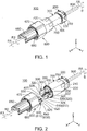
Fig. 1 is a perspective view showing a connector according to an embodiment of the present invention. In the figure, a female screw portion of a coupling nut is meshed with both of a first male screw portion of a first holding member and a second male screw portion of a second holding member. -
Fig. 2 is an exploded, perspective view showing the connector ofFig. 1 . In the figure, the female screw portion of the coupling nut is not meshed with any of the first male screw portion of the first holding member and the second male screw portion of the second holding member. In addition, an optical module is held by the second holding member and is not connected with an optical connector. -
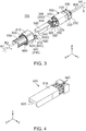
Fig. 3 is another exploded, perspective view showing the connector ofFig. 1 . In the figure, the optical module is connected with the optical connector. -
Fig. 4 is a perspective view showing the optical module which is included in the connector ofFig. 3 . -
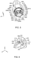
Fig. 5 is a perspective view showing the second holding member which is included in the connector ofFig. 3 . -
Fig. 6 is a perspective view showing the optical connector which is included in the connector ofFig. 2 . -
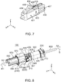
Fig. 7 is a perspective view showing an optical connector main which is included in the optical connector ofFig. 6 . -
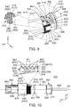
Fig. 8 is a perspective view showing a state where the connector ofFig. 3 arrives and where protruding pieces of a first guide portion of the first holding member are inserted into ditches, respectively, of a second guide portion of the second holding member. In the figure, the coupling nut is omitted. -
Fig. 9 is a partially enlarged, perspective view showing the connector ofFig. 8 . In the figure, the first male screw portion and the second male screw portion are further partially enlarged. -
Fig. 10 is a view showing the connector ofFig. 8 . In the figure, the first male screw portion and the second male screw portion are partially enlarged. -
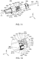
Fig. 11 is another perspective view showing a state where the connector ofFig. 3 arrives and where the protruding pieces of the first guide portion of the first holding member are inserted into the ditches, respectively, of the second guide portion of the second holding member. In the figure, the coupling nut is omitted. -
Fig. 12 is a partially enlarged, perspective view showing the connector ofFig. 11 . -
Fig. 13 is a view showing the connector ofFig. 11 . In the figure, the first male screw portion and the second male screw portion are partially enlarged. -
Fig. 14 is a side view for use in explaining a procedure of replacing the optical module of the connector ofFig. 1 . In the figure, the protruding pieces of the first guide portion of the first holding member are not inserted into the ditches of the second guide portion of the second holding member. -
Fig. 15 is a top view showing the connector ofFig. 14 . -
Fig. 16 is a cross-sectional view showing the connector ofFig. 15 , taken along line A-A. In the figure, the first holding member and the coupling nut are partially enlarged. -
Fig. 17 is another side view for use in explaining the procedure of replacing the optical module of the connector ofFig. 1 . In the figure, the protrusion pieces of the first guide portion of the first holding member are inserted into the ditches, respectively, of the second guide portion of the second holding member while the female screw portion of the coupling nut is not meshed with any of the first male screw portion of the first holding member and the second male screw portion of the second holding member. -
Fig. 18 is a top view showing the connector offig. 17 . -
Fig. 19 is a cross-sectional view showing the connector ofFig. 18 , taken along line B-B. -
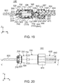
Fig. 20 is a top view for use in explaining the procedure of replacing the optical module of the connector ofFig. 1 . In the figure, the protruding pieces of the first guide portion of the first holding member are inserted into the ditches, respectively, of the second guide portion of the second holding member and the female screw portion of the coupling nut is meshed with the second male screw portion of the second holding member and the female screw portion of the coupling nut is not meshed with the first male screw portion of the first holding member. -
Fig. 21 is a cross-sectional view showing the connector ofFig. 20 , taken along line C-C. -
Fig. 22 is another top view for use in explaining the procedure of replacing the optical module of the connector ofFig. 1 . In the Figure, the female screw portion of the coupling nut is meshed with both of the first male screw portion of the first holding member and the second male screw portion of the second holding member. -
Fig. 23 is a cross-sectional view showing the connector ofFig. 22 , taken along line D-D. -
Fig. 24 is a side view showing a connector and an adaptor ofPatent Document 1. -
Fig. 25 is a cross-sectional view showing the connector and the adaptor ofFig. 24 . - While the invention is susceptible to various modifications and alternative forms, specific embodiments thereof are shown by way of example in the drawings and will herein be described in detail. It should be understood, however, that the drawings and detailed description thereto are not intended to limit the invention to the particular form disclosed, but on the contrary, the intention is to cover all modifications, equivalents and alternatives falling within the spirit and scope of the present invention as defined by the appended claims.
- As shown in
Fig. 2 , aconnector 100 according to an embodiment of the present invention comprises acable holding portion 200, a first holdingmember 300, anoptical connector 400, anoptical module 500, asecond holding member 600 and acoupling nut 700. - As shown in
Fig. 1 , thecable holding portion 200 of the present embodiment is positioned rearward of the first holdingmember 300 in a front-rear direction. A rear end of thecable holding portion 200 is a rearmost end of theconnector 100. As shown inFig. 16 , thecable holding portion 200 holds anoptical fiber cable 800 which transmits optical signals. In the present embodiment, the front-rear direction is an X-direction. Specifically, it is assumed that forward is a positive X-direction while rearward is a negative X-direction. - As shown in
Figs. 1 and8 , thecable holding portion 200 of the present embodiment has a disc-like portion 210 and atube portion 220. - As shown in
Figs. 8 and16 , the disc-like portion 210 of the present embodiment has a substantially discoid shape which is centered on an axis AX parallel to the front-rear direction. The disc-like portion 210 has ahole 212 which pierces the disc-like portion 210 in the front-rear direction. The disc-like portion 210 is positioned rearward of thetube portion 220 in the front-rear direction. More specifically, a front end of the disc-like portion 210 is coupled with a rear end of thetube portion 220 in the front-rear direction. Theoptical fiber cable 800 is held by thecable holding portion 200 so as to pass through thehole 212 of the disc-like portion 210 of thecable holding portion 200. - As shown in
Figs. 8 and16 , thetube portion 220 of the present embodiment has a shape which is rotationally symmetric with respect to the axis AX. More specifically, thetube portion 220 has a polygonal tubular shape which is centered on the axis AX and which extends in the front-rear direction. An inner wall of thetube portion 220 is provided with afemale screw 222. - As shown
Figs. 8 and16 , the first holdingmember 300 of the present embodiment holds theoptical connector 400. More specifically, the first holdingmember 300 holds theoptical connector 400 so that theoptical connector 400 is movable in the front-rear direction. - As shown in
Fig. 8 , the first holdingmember 300 of the present embodiment has a firstcylindrical portion 305, afirst guide portion 310 and firstmale screw portions 330. - As shown in
Figs. 2 ,8 and16 , the firstcylindrical portion 305 of the present embodiment has a substantially cylindrical shape which is centered on the axis AX and which extends in the front-rear direction. The firstcylindrical portion 305 hasfront regulating portions 350, arear regulating portion 360, an O-ring 307, afirst protrusion 308 and amale screw 306. In other words, the first holdingmember 300 has the front regulatingportions 350 and therear regulating portion 360. - As shown in
Figs. 2 and9 , each of the front regulatingportions 350 of the present embodiment is positioned at a front end of the firstcylindrical portion 305 in the front-rear direction. Each of the front regulatingportions 350 protrudes inward in a radial direction perpendicular to the axis AX. More specifically, each of the front regulatingportions 350 protrudes inward in a lateral direction perpendicular to the front-rear direction. In the present embodiment, the lateral direction is a Y-direction. - As shown in
Fig. 16 , therear regulating portion 360 of the present embodiment is positioned around the front end of the firstcylindrical portion 305. Referring toFigs. 2 and16 , therear regulating portion 360 is positioned rearward of thefront regulating portion 350 in the front-rear direction. Therear regulating portion 360 is positioned forward of the O-ring 307 in the front-rear direction. Therear regulating portion 360 is a plane facing forward in the front-rear direction. - Referring to
Fig. 16 , the O-ring 307 of the present embodiment has an annular shape which is centered on the axis AX. The O-ring 307 is arranged on an outer circumferential surface of the firstcylindrical portion 305. The O-ring 307 is arranged around the front end of the firstcylindrical portion 305. The O-ring 307 is positioned between therear regulating portion 360 and thefirst protrusion 308 in the front-rear direction. Specifically, the O-ring 307 is positioned rearward of therear regulating portion 360 and forward of thefirst protrusion 308. - As shown in
Fig. 16 , thefirst protrusion 308 of the present embodiment protrudes outward in the radial direction from the outer circumferential surface of the firstcylindrical portion 305. Thefirst protrusion 308 is positioned between the O-ring 307 and themale screw 306 in the front-rear direction. Specifically, thefirst protrusion 308 is positioned rearward of the O-ring 307 and forward of themale screw 306. - As shown in
Fig. 16 , themale screw 306 of the present embodiment is positioned at a rear end of the firstcylindrical portion 305. Themale screw 306 is screwed into thefemale screw 222 of thetube portion 220 of thecable holding portion 200. In other words, thecable holding portion 200 is attached with the first holdingmember 300. - As shown in
Figs. 2 and9 , thefirst guide portion 310 of the present embodiment extends forward in the front-rear direction from the front end of the firstcylindrical portion 305. Thefirst guide portion 310 comprises two protrudingpieces 320. Each of the protrudingpieces 320 extends forward in the front-rear direction. Each of the protrudingpieces 320 has a rectangular shape when viewed in the lateral direction. Each of the protrudingpieces 320 has anupper surface 322 and alower surface 324. Theupper surface 322 is perpendicular to an up-down direction. Thelower surface 324 is perpendicular to the up-down direction. In the present embodiment, the up-down direction is a Z-direction. It is assumed that upward is a positive Z-direction while downward is a negative Z-direction. Each of the protrudingpieces 320 has anouter surface 326 and aninner surface 328. Theouter surface 326 faces outward in the lateral direction. Theinner surface 328 faces inward in the lateral direction. Theinner surface 328 of the protrudingpiece 320 is positioned outward of thefront regulating portion 350 of the firstcylindrical portion 305 in the lateral direction. However, the present invention is not limited thereto. But, thefirst guide portion 310 should comprise at least one of the protrudingpiece 320 which extends forward in the front-rear direction. - As shown in
Figs. 2 and9 , the firstmale screw portions 330 of the present embodiment are provided on the protrudingpieces 320, respectively, of thefirst guide portion 310. More specifically, the firstmale screw portion 330 is provided on theouter surface 326 of the protrudingpiece 320, andscrew threads 340 of the firstmale screw portion 330 protrude outward in the lateral direction. Referring toFigs. 8 to 10 , the firstmale screw portion 330 has thescrew threads 340. Thescrew thread 340 of the firstmale screw portion 330 has anintersecting surface 342. The intersectingsurface 342 is positioned at an end of thescrew thread 340 of the firstmale screw portion 330 in a second rotation direction R2 of a circumferential direction S about the axis AX. The intersectingsurface 342 intersects with a first rotation direction R1. The first rotation direction R1 is opposite to the second rotation direction R2. In other words, the second rotation direction R2 is opposite to the first rotation direction R1. More specifically, the intersectingsurface 342 is inclined so as to extend forward and upward. Thescrew threads 340 of the firstmale screw portion 330 are arranged at pitches P1 in the front-rear direction. In the present embodiment, the first rotation direction R1 is a clockwise direction when theconnector 100 is viewed from its front, while the second rotation direction R2 is a counterclockwise direction when theconnector 100 is viewed from its front. - As shown in
Fig. 16 , the first holdingmember 300 further comprises apressing member 370. The pressingmember 370 is aspring member 370 which is accommodated in the first holdingmember 300. More specifically, thespring member 370 is accommodated into the firstcylindrical portion 305 of the first holdingmember 300. Thespring member 370 of the present embodiment is a coil spring extending in the front-rear direction. - Referring to
Figs. 2 and16 , theoptical connector 400 of the present embodiment connects theoptical fiber cable 800 and theoptical module 500 with each other. Specifically, theoptical connector 400 is attached with theoptical fiber cable 800, and theoptical connector 400 is attachable with and detachable from theoptical module 500. - As shown in
Figs. 2 and9 , theoptical connector 400 of the present embodiment is held around the front end of the firstcylindrical portion 305 of the first holdingmember 300. A front end of theoptical connector 400 is positioned forward beyond the front end of the firstcylindrical portion 305 of the first holdingmember 300. Theoptical connector 400 is positioned between the two protrudingpieces 320 of the first holdingmember 300 in the lateral direction perpendicular to both the front-rear direction and the up-down direction. A connecting part of theoptical connector 400 and theoptical module 500 is positioned forward of the firstcylindrical portion 305 of the first holdingmember 300 in the front-rear direction. - As shown in
Fig. 6 , theoptical connector 400 of the present embodiment has an optical connector main 401 and an extendingportion 410. The extendingportion 410 is perpendicular to the front-rear direction. - As shown in
Fig. 7 , the optical connector main 401 of the present embodiment has an optical fibercable accommodating portion 403, receivingportions 406,hook portions 407, a supportingportion 404, pressedportions 402 and engagingportions 409. - As shown in
Fig. 7 , the optical fibercable accommodating portion 403 has a substantially rectangular tube shape extending in the front-rear direction. - As shown in
Fig. 7 , each of the receivingportions 406 of the present embodiment is provided around a middle of an upper surface of the optical fibercable accommodating portion 403 in the front-rear direction. Each of the receivingportions 406 is a rear surface of a protrusion which protrudes upward in the up-down direction. - As shown in
Fig. 7 , each of thehook portions 407 of the present embodiment is positioned at a rear end of the optical fibercable accommodating portion 403 in the front-rear direction. Each of thehook portions 407 has a hook-like shape which protrudes outward in the radial direction. Each of thehook portions 407 has afront surface 408 facing forward in the front-rear direction. Each of thehook portions 407 is movable in the radial direction. - As shown in
Fig. 7 , the supportingportion 404 of the present embodiment extends rearward and upward from a front end of the upper surface of the optical fibercable accommodating portion 403. The supportingportion 404 is supported by the optical fibercable accommodating portion 403 in a cantilever manner. The supportingportion 404 is elastically deformable. - As shown in
Fig. 7 , each of the pressedportions 402 of the present embodiment is positioned at an upper, rear end of the supportingportion 404. - As shown
Fig. 7 , each of the engagingportions 409 of the present embodiment is a plane intersecting with the front-rear direction. Each of the engagingportions 409 is positioned in the vicinity of a rear end of the supportingportion 404. Since the supportingportion 404 is elastically deformable as described above, each of the engagingportions 409 is movable in the up-down direction. Specifically, when the pressedportions 402 are pressed from above, the supportingportion 404 is elastically deformed so that the engagingportions 409 are moved downward. When the pressing against the pressedportions 402 is stopped, the supportingportion 404 restores its original shape so that the engagingportions 409 are moved upward to return to their original positions. - As shown in
Fig. 6 , the extendingportion 410 of the present embodiment is positioned around a rear end of theoptical connector 400 in the front-rear direction. In the radial direction, an outer circumference of the extendingportion 410 defines an outermost circumference of theoptical connector 400. - As shown in
Figs. 6 and16 , the extendingportion 410 of the present embodiment has a hole 411, arear surface 412, an abuttingportion 414, frontregulated portions 416 and a rearregulated portion 418. Therear surface 412 faces rearward in the front-rear direction. The abuttingportion 414 faces forward in the front-rear direction. - As shown in
Fig. 6 , the hole 411 pierces the extendingportion 410 in the front-rear direction. Referring toFig. 16 , therear surface 412 is a plane perpendicular to the front-rear direction. Referring toFig. 6 again, the abuttingportion 414 is a plane perpendicular to the front-rear direction. Each of the frontregulated portions 416 is a plane perpendicular to the front-rear direction. Each of the frontregulated portions 416 is positioned rearward of the abuttingportion 414 in the front-rear direction. The rearregulated portion 418 is a plane perpendicular to the front-rear direction. The rearregulated portion 418 is positioned rearward of the frontregulated portion 416 in the front-rear direction. Referring toFig. 16 again, the rearregulated portion 418 is positioned outward of therear surface 412 in the radial direction. Therear surface 412 and the rearregulated portion 418 are positioned on a common plane perpendicular to the front-rear direction. - Referring to
Figs. 9 and16 , the extendingportion 410 of the present embodiment is positioned between thefront regulating portion 350 and therear regulating portion 360 of the firstcylindrical portion 305 of the first holdingmember 300 in the front-rear direction. Specifically, in the front-rear direction, the extendingportion 410 is positioned rearward of thefront regulating portion 350 and forward of therear regulating portion 360. The frontregulated portions 416 of the extendingportion 410 face the front regulatingportions 350, respectively, of the firstcylindrical portion 305 of the first holdingmember 300 in the front-rear direction. The rearregulated portion 418 of the extendingportion 410 faces therear regulating portion 360 of the firstcylindrical portion 305 of the first holdingmember 300 in the front-rear direction. The extendingportion 410 is movable by a predetermined distance PD between thefront regulating portion 350 and therear regulating portion 360 of the firstcylindrical portion 305 of the first holdingmember 300. Specifically, the first holdingmember 300 is movable forward by the predetermined distance PD with respective to theoptical connector 400. Thespring member 370 of the first holdingmember 300 presses the extendingportion 410 forward in the front-rear direction. More specifically, thespring member 370 of the first holdingmember 300 pushes therear surface 412 of the extendingportion 410 to press the frontregulated portions 416 of the extendingportion 410 against the front regulatingportions 350, respectively, of the firstcylindrical portion 305 of the first holdingmember 300. Specifically, the first holdingmember 300 further comprises thepressing member 370 which presses the extendingportion 410 of theoptical connector 400 against the front regulatingportions 350. - As understood from
Figs. 6 and7 , the extendingportion 410 of the present embodiment is held between the receivingportion 406 and thefront surface 408 of thehook portion 407 of the optical connector main 401. The receivingportion 406 of the optical connector main 401 faces the abuttingportion 414 of the extendingportion 410 in the front-rear direction. - Referring to
Figs. 4 and16 , theoptical module 500 of the present embodiment is an SFP (Small Form-factor pluggable) module. Specifically, theoptical module 500 sends optical signals to theoptical connector 400 and receives optical signals from theoptical connector 400. - As shown in
Figs. 4 and16 , theoptical module 500 of the present embodiment comprises anelectrical connector 520, aphotoelectric conversion portion 510, lockedportions 530 and engagedportions 540. - Referring to
Figs. 4 and16 , theelectrical connector 520 sends electrical signals to thephotoelectric conversion portion 510 and receives electrical signals from thephotoelectric conversion portion 510. Thephotoelectric conversion portion 510 converts optical signals to electrical signals and vice versa between theoptical connector 400 and theelectrical connector 520. Each of the lockedportions 530 protrudes downward in the up-down direction. Each of the engagedportions 540 is a plane facing forward. Each of the engagedportions 540 is positioned around a rear end of theoptical module 500. - As shown in
Figs. 3 and16 , theoptical module 500 of the present embodiment is connected with theoptical connector 400. The engaged portions 540 (seeFig. 4 ) of theoptical module 500 are positioned rearward of the engaging portions 409 (seeFig. 7 ), respectively, of theoptical connector 400 in the front-rear direction. Specifically, the engagedportions 540 of theoptical module 500 face the engagingportions 409, respectively, of theoptical connector 400 in the front-rear direction. Theoptical module 500 is replaceable in theconnector 100 of the present embodiment. A method of replacing theoptical module 500 is described later. - As shown in
Fig. 1 , the second holdingmember 600 of the present embodiment is positioned forward of the first holdingmember 300 in the front-rear direction. A front end of the second holdingmember 600 is a frontmost end of theconnector 100. - As shown in
Figs. 15 and 16 , the second holdingmember 600 of the present embodiment has acover portion 650, a secondcylindrical portion 660, asecond guide portion 610, secondmale screw portions 640, a thirdmale screw portion 644 and an outertubular portion 670. - As shown in
Figs. 1 to 3 , thecover portion 650 of the present embodiment has a substantially rectangular half-tube shape. The substantially rectangular half-tube shape of thecover portion 650 extends in the front-rear direction and opens downward. Thecover portion 650 is positioned forward of the secondcylindrical portion 660 in the front-rear direction. Specifically, a rear end of thecover portion 650 is coupled with a front end of the secondcylindrical portion 660 in the front-rear direction. - As understood from
Figs. 3 and5 , the secondcylindrical portion 660 of the present embodiment has a shape which is rotationally symmetric with respect to the axis AX. More specifically, the secondcylindrical portion 660 of the present embodiment has a cylindrical shape which is centered on the axis AX and which extends in the front-rear direction. As shown inFig. 8 , the connecting part of theoptical connector 400 and theoptical module 500 is positioned rearward of the secondcylindrical portion 660 in the front-rear direction. Specifically, the connecting part of theoptical connector 400 and theoptical module 500 is positioned between the firstcylindrical portion 305 of the first holdingmember 300 and the secondcylindrical portion 660 of the second holdingmember 600 in the front-rear direction. - As shown in
Fig. 16 , the secondcylindrical portion 660 of the present embodiment has anaccommodating portion 662, three O-rings portions 666 and asecond protrusion 667. - As shown in
Fig. 5 , theaccommodating portion 662 of the present embodiment is a hole which has a rectangular tube shape and which pierces the secondcylindrical portion 660 in the front-rear direction. As shown inFig. 16 , a front end of theaccommodating portion 662 is coupled with the rear end of the substantially rectangular half-tube of thecover portion 650. Specifically, theaccommodating portion 662 of the secondcylindrical portion 660 and the substantially rectangular half-tube of thecover portion 650 form a space which accommodates theoptical module 500. - Referring to
Fig. 16 , each of the O-rings rings cylindrical portion 660. The O-ring 663 is the frontmost of the O-rings ring 665 is the rearmost of the O-rings ring 664 is positioned between the O-rings - As shown in
Figs. 5 and16 , each of the lockingportions 666 of the present embodiment is provided on a lower inner wall of theaccommodating portion 662. The lockingportions 666 fix theoptical module 500 to the second holdingmember 600 by being engaged with the lockedportions 530, respectively, of theoptical module 500 when theoptical module 500 is inserted into the second holdingmember 600. In other words, the second holdingmember 600 of theconnector 100 of the present embodiment holds theoptical module 500. - As shown in
Fig. 16 , thesecond protrusion 667 of the present embodiment protrudes outward in the radial direction from the outer circumferential surface of the secondcylindrical portion 660. Thesecond protrusion 667 is positioned between the O-rings - As shown in
Fig. 5 , thesecond guide portion 610 of the present embodiment extends rearward from a rear end of the secondcylindrical portion 660. Thesecond guide portion 610 comprises twoditches 620 and fourwall portions 630. More specifically, thesecond guide portion 610 has two guide pairs 615 each consisting of thesingle ditch 620 and two of thewall portions 630. However, the present invention is not limited thereto. Thesecond guide portion 610 may be modified, provided that thesecond guide portion 610 comprises at least one of theditch 620 and at least two of thewall portions 630. - As shown in
Fig. 15 , the guide pairs 615 of the present embodiment correspond to the protrudingpieces 320, respectively, of thefirst guide portion 310 of the first holdingmember 300. The two guide pairs 615 are spaced apart from each other in the lateral direction. As shown inFig. 5 , in eachguide pair 615, thewall portions 630 are arranged opposite to each other with theditch 620 left therebetween in the up-down direction perpendicular to the front-rear direction. Theditch 620 extends in the front-rear direction. Theditch 620 opens rearward in the front-rear direction. Theditch 620 is recessed inward in the lateral direction. Theditch 620 has twowall surfaces side surface 626. Each of the wall surfaces 622, 624 is perpendicular to the up-down direction. Theside surface 626 intersects with the lateral direction. Specifically, in eachditch 620, theside surface 626 connects inner ends in the lateral direction of the twowall surfaces Figs. 17 and 18 , when the second holdingmember 600 is mated with the first holdingmember 300, theditches 620 receive the protrudingpieces 320, respectively, of thefirst guide portion 310. Meanwhile, thewall surface 622, which is positioned at an upper side of theditch 620, faces theupper surface 322 of the corresponding protrudingpiece 320 in the up-down direction while thewall surface 624, which is positioned at a lower side of theditch 620, faces thelower surface 324 of the corresponding protrudingpiece 320 in the up-down direction. Also meanwhile, theside surface 626 of theditch 620 faces theinner surface 328 of the corresponding protrudingpiece 320 in the lateral direction. However, the present invention is not limited thereto. But, at least two of thewall portions 630 should be arranged opposite to each other with the at least one of theditch 620 left therebetween in the up-down direction perpendicular to the front-rear direction. In addition, at least one of theditch 620, which extends in the front-rear direction while opening rearward in the front-rear direction, at least in part, should receive at least one of the protrudingpiece 320. - As described above, the
connector 100 of the present embodiment is configured so that the protrudingpieces 320 of thefirst guide portion 310 of the first holdingmember 300 are received in theditches 620, respectively, which are of thesecond guide portion 610 of the second holdingmember 600 and each of which opens rearward. Accordingly, a relative movement of the first holdingmember 300 with respect to the second holdingmember 600 in the front-rear direction is allowed while a relative movement of the first holdingmember 300 with respect to the second holdingmember 600 in the circumferential direction S is regulated. Specifically, in cooperation with each other, thefirst guide portion 310 and thesecond guide portion 610 allow the relative movement of the first holdingmember 300 with respect to the second holdingmember 600 in the front-rear direction while regulating the relative movement of the first holdingmember 300 with respect to the second holdingmember 600 in the circumferential direction S about the axis AX parallel to the front-rear direction. - As shown in
Fig. 5 , the secondmale screw portions 640 of the present embodiment are formed on thewall portions 630, respectively.Screw threads 642 of the secondmale screw portion 640 protrude outward in the radial direction. As shown inFig. 13 , thescrew threads 642 of the secondmale screw portion 640 are arranged at pitches P2 in the front-rear direction. As shown inFig. 17 , a position of the firstmale screw portion 330 matches a position of the secondmale screw portion 640 in the front-rear direction under a state where the protrudingpiece 320 of thefirst guide portion 310 is received in theditch 620. More specifically, the firstmale screw portion 330 of the protrudingpiece 320 is positioned between thescrew thread 642, which is the frontmost of thescrew threads 642, and thescrew thread 642, which is the rearmost of thescrew threads 642, of the secondmale screw portion 640 of thewall portion 630 of thecorresponding guide pair 615 in the front-rear direction. Specifically, in the front-rear direction, a size of the firstmale screw portion 330 is smaller than a size of the secondmale screw portion 640. The firstmale screw portion 330 of the protrudingpiece 320 is positioned between the secondmale screw portions 640 of thewall portions 630 of thecorresponding guide pair 615 in the up-down direction. - As shown in
Fig. 5 , the thirdmale screw portion 644 of the present embodiment has a substantially half-cylindrical shape which extends in the front-rear direction. The thirdmale screw portion 644 extends rearward from the rear end of the secondcylindrical portion 660. In the lateral direction, the thirdmale screw portion 644 is positioned between thewall portion 630, which is positioned at a lower side of one of the guide pairs 615, and thewall portion 630 which is positioned at a lower side of a remaining one of the guide pairs 615. In other words, the thirdmale screw portion 644 couples thewall portions 630, which are positioned at the lower sides of the two guide pairs 615, with each other in the lateral direction.Screw threads 646 of the thirdmale screw portion 644 are coupled with thescrew threads 642 of the secondmale screw portion 640 in the circumferential direction S. - As shown in
Figs. 3 and5 , the outertubular portion 670 of the present embodiment has a shape which is rotationally symmetric with respect to the axis AX. More specifically, the outertubular portion 670 of the present embodiment has a polygonal tubular shape which is centered on the axis AX and which extends in the front-rear direction. The outertubular portion 670 is formed to have a radial size greater than a radial size of the secondcylindrical portion 660. Specifically, the outertubular portion 670 is positioned outward of the secondcylindrical portion 660 in the radial direction. An inner circumferential surface of the outertubular portion 670 and the outer circumferential surface of the secondcylindrical portion 660 form a substantially annular space which extends in the front-rear direction. As shown inFig. 16 , the outertubular portion 670 has aprotrusion 672 which protrudes inward in the radial direction from its inner circumferential surface. Theprotrusion 672 of the outertubular portion 670 is positioned rearward of thesecond protrusion 667 of the secondcylindrical portion 660 in the front-rear direction. - As shown in
Fig. 2 , thecoupling nut 700 of the present embodiment has a shape which is rotationally symmetric with respect to the axis AX. More specifically, thecoupling nut 700 of the present embodiment has a substantially cylindrical shape which is centered on the axis AX and which extends in the front-rear direction. As shown inFig. 16 , thecoupling nut 700 is positioned outward of the first holdingmember 300 in the radial direction. - As shown in
Fig. 21 , thecoupling nut 700 of the present embodiment has afirst contact portion 730, afemale screw portion 710, asecond contact portion 740 and asmaller diameter portion 750. - As shown in
Fig. 23 , thefirst contact portion 730 of the present embodiment is a part of an inner circumferential surface of thecoupling nut 700. Thefirst contact portion 730 is positioned around a front end of thecoupling nut 700. When thefemale screw portion 710 of thecoupling nut 700 is meshed with both of the firstmale screw portion 330 of the first holdingmember 300 and the secondmale screw portion 640 of the second holdingmember 600, thefirst contact portion 730 is accommodated in the substantially annular space which is formed by the inner circumferential surface of the outertubular portion 670 and the outer circumferential surface of the secondcylindrical portion 660. Meanwhile, thefirst contact portion 730 is in contact with both of the O-rings cylindrical portion 660 of the second holdingmember 600 in the radial direction. - As shown in
Fig. 21 , thefemale screw portion 710 of the present embodiment is positioned rearward of thefirst contact portion 730 in the front-rear direction.Screw threads 720 of thefemale screw portion 710 protrude inward in the radial direction from the inner circumferential surface of thecoupling nut 700. Referring toFig. 16 , thescrew threads 720 of thefemale screw portion 710 are arranged at pitches P3 in the front-rear direction. Referring toFigs. 16 ,13 and10 , the pitch P3 of thescrew threads 720 of thefemale screw portion 710 is equal to any of the pitch P1 of thescrew threads 340 of the firstmale screw portion 330 and the pitch P2 of thescrew threads 642 of the secondmale screw portion 640. As described above, the extendingportion 410 of theoptical connector 400 is movable by the predetermined distance PD between thefront regulating portion 350 and therear regulating portion 360 of the first holdingmember 300. Referring toFigs. 9 and16 , the predetermined distance PD is greater than the pitch P3 of thefemale screw portion 710. - Referring to
Fig. 23 , when thefemale screw portion 710 of thecoupling nut 700 is meshed with both of the firstmale screw portion 330 of the first holdingmember 300 and the secondmale screw portion 640 of the second holdingmember 600, the relative movements of the first holdingmember 300 and the second holdingmember 600 in the front-rear direction are prevented by thescrew threads 720 of thefemale screw portion 710. In other words, relative positions of the first holdingmember 300 and the second holdingmember 600 in the front-rear direction are maintained by thefemale screw portion 710 being meshed with both of the firstmale screw portion 330 of the first holdingmember 300 and the secondmale screw portion 640 of the second holdingmember 600. When thefemale screw portion 710 is meshed with both the firstmale screw portion 330 of the first holdingmember 300 and the secondmale screw portion 640 of the second holdingmember 600, the position of the firstmale screw portion 330 matches the position of the secondmale screw portion 640 in the front-rear direction. However, the present invention is not limited thereto. But, the position of the firstmale screw portion 330 should overlap with the position of secondmale screw portion 640 in the front-rear direction when thefemale screw portion 710 is meshed with both of the firstmale screw portion 330 and the secondmale screw portion 640. - As shown in
Fig. 23 , thesecond contact portion 740 of the present embodiment is a part of the inner circumferential surface of thecoupling nut 700. Thesecond contact portion 740 is positioned rearward of thefemale screw portion 710 in the front-rear direction. When thefemale screw portion 710 of thecoupling nut 700 is meshed with both of the firstmale screw portion 330 of the first holdingmember 300 and the secondmale screw portion 640 of the second holdingmember 600, thesecond contact portion 740 is in contact with the O-ring 307 of the firstcylindrical portion 305 of the first holdingmember 300 in the radial direction. - As described above, the
first contact portion 730 and thesecond contact portion 740 of thecoupling nut 700 are in contact with the outer circumferential surface of the firstcylindrical portion 305 of the first holdingmember 300 and the outer circumferential surface of the secondcylindrical portion 660 of the second holdingmember 600 via the O-rings female screw portion 710 of thecoupling nut 700 is meshed with both of the firstmale screw portion 330 of the first holdingmember 300 and the secondmale screw portion 640 of the second holdingmember 600. Accordingly, the connecting part of theoptical connector 400 and theoptical module 500, which is positioned between the firstcylindrical portion 305 and the secondcylindrical portion 660, is shielded from the outside of theconnector 100. Specifically, the connecting part of theoptical connector 400 and theoptical module 500 is waterproofed from the outside of theconnector 100. - As shown in
Fig. 23 , thesmaller diameter portion 750 of the present embodiment is positioned at a rear end of thecoupling nut 700. Thesmaller diameter portion 750 protrudes inward in the radial direction from the inner circumferential surface of thecoupling nut 700. Thesmaller diameter portion 750 is positioned rearward of thesecond contact portion 740 in the front-rear direction. Thesmaller diameter portion 750 is positioned rearward of thefirst protrusion 308 of the firstcylindrical portion 305 of the first holdingmember 300 in the front-rear direction. When thefemale screw portion 710 of thecoupling nut 700 is meshed with both of the firstmale screw portion 330 of the first holdingmember 300 and the secondmale screw portion 640 of the second holdingmember 600, a front surface of thesmaller diameter portion 750 faces a rear surface of thefirst protrusion 308 of the firstcylindrical portion 305 of the first holdingmember 300 in the front-rear direction. - Referring to
Fig. 23 , theconnector 100 of the present embodiment is configured so that the second holdingmember 600, which holds theoptical module 500 having a greater size in the front-rear direction, is positioned farther away from the first holdingmember 300 in the front-rear direction than the second holdingmember 600 which holds theoptical module 500 having a smaller size in the front-rear direction. Specifically, theconnector 100 of the present embodiment is configured so that a size difference of theoptical modules 500 in the front-rear direction is negated by a positional difference of the second holdingmember 600 with respect to the first holdingmember 300 in the front-rear direction. Accordingly, theoptical fiber cable 800 can have a constant length between theoptical connector 400 and thecable holding portion 200, and thereby theoptical fiber cable 800 can be prevented from having an excess length to be bent in theconnector 100 even if theoptical module 500 is replaced with anotheroptical module 500 having a different size in the front-rear direction. - Hereinafter, description will be made about a method of replacing the
optical module 500 in theconnector 100 of the present embodiment. - First, in the
connector 100 shown inFig. 1 , thecoupling nut 700 is rotated in the second rotation direction R2 of the circumferential direction S with respect to both the first holdingmember 300 and the second holdingmember 600. Then, thefemale screw portion 710 of thecoupling nut 700 is unmeshed from both of the firstmale screw portion 330 of the first holdingmember 300 and the secondmale screw portion 640 of the second holdingmember 600. Specifically, thecoupling nut 700 is movable rearward of any of the firstmale screw portion 330 of the first holdingmember 300 and the secondmale screw portion 640 of the second holdingmember 600. - When the second holding
member 600, which holds theoptical module 500, is moved forwardly away from the first holdingmember 300 under this state, theoptical connector 400 and theoptical module 500 are unconnected from each other so that theconnector 100 reaches a state shown inFig. 2 . In the state shown inFig. 2 , theoptical module 500 is removed from the second holdingmember 600 by being pulled rearward therefrom. - After that, a new
optical module 500 is attached with theoptical connector 400, which is held by the first holdingmember 300, so that theconnector 100 reaches a state shown inFig. 3 . When the second holdingmember 600 is moved rearward with respect to theoptical module 500 in the state shown inFig. 3 so that theoptical module 500 is inserted into theaccommodating portion 662 of the secondcylindrical portion 660 from a rear end of theaccommodating portion 662, the second holdingmember 600 is mated with the first holdingmember 300. Thus, the locking portions 666 (seeFig. 16 ) of the second holdingmember 600 are engaged with the locked portions 530 (seeFig. 16 ), respectively, of theoptical module 500 and thereby theoptical module 500 is fixed to the second holdingmember 600. Specifically, theconnector 100 reaches a state shown inFig. 19 . However, the present invention is not limited thereto. Theconnector 100 may reach the state shown inFig. 19 as follows: a newoptical module 500 is fixed to the second holdingmember 600; and the second holdingmember 600, to which the newoptical module 500 is fixed, approaches the first holdingmember 300. - Referring to
Figs. 8 and20 to 23 , when thecoupling nut 700 is moved forward with respect to both of the first holdingmember 300 and the second holdingmember 600 while being rotated in the first rotation direction R1 of the circumferential direction S with respect to both of the first holdingmember 300 and the second holdingmember 600, thefemale screw portion 710 of thecoupling nut 700 is meshed with the secondmale screw portions 640 of thewall portions 630 of thesecond guide portion 610 of the second holdingmember 600 and is then meshed with the firstmale screw portions 330 of the protrudingpieces 320 of thefirst guide portion 310 of the first holdingmember 300. - Referring to
Figs. 10 and13 , if thefemale screw portion 710 of thecoupling nut 700 and the firstmale screw portion 330 of the first holdingmember 300 are deviated from each other in the front-rear direction upon the meshing thereof, the deviation of thefemale screw portion 710 and the firstmale screw portion 330 in the front-rear direction is eliminated as follows; when thefemale screw portion 710, which is meshed with the secondmale screw portion 640 of the second holdingmember 600, begins to be meshed with the firstmale screw portion 330, a leading end 722 (seeFig. 16 ) of thescrew thread 720 of thefemale screw portion 710 abuts against the intersectingsurface 342 of thescrew thread 340 of the firstmale screw portion 330 to move the firstmale screw portion 330 in the front-rear direction. - More specifically, referring to
Fig. 10 , if thefemale screw portion 710 of thecoupling nut 700 and the firstmale screw portion 330 of the first holdingmember 300 are deviated from each other in the front-rear direction upon the meshing thereof, the deviation of thefemale screw portion 710 and the firstmale screw portion 330 in the front-rear direction is eliminated as follows. When thefemale screw portion 710, which is meshed with the secondmale screw portion 640 of the second holdingmember 600, begins to be meshed with the firstmale screw portion 330, the leading end 722 (seeFig. 16 ) of thescrew thread 720 of thefemale screw portion 710 abuts against the intersectingsurface 342 of thescrew thread 340 of the firstmale screw portion 330 to apply a force, which is directed in the first rotation direction R1, to theintersecting surface 342. Since the intersectingsurface 342 is inclined so as to extend forward and upward as described above, the force directed in the first rotation direction R1, which is applied to theintersecting surface 342, is converted to a forward force. In addition, the first holdingmember 300 is movable forward by the predetermined distance PD with respect to theoptical connector 400 as described above. Accordingly, referring toFig. 13 , the firstmale screw portion 330 is moved forward until thefemale screw portion 710 and the firstmale screw portion 330 are positioned at the same position as each other in the front-rear direction. In other words, the deviation of thefemale screw portion 710 and the firstmale screw portion 330 in the front-rear direction is eliminated. - When the
coupling nut 700 continues to be rotated in the first rotation direction R1 with respect to both of the first holdingmember 300 and the second holdingmember 600 under a state where the deviation is eliminated, thefemale screw portion 710 is meshed with both of the firstmale screw portion 330 and the secondmale screw portion 640. - As described above, a size difference of
optical modules 500 in the front-rear direction is negated by a positional difference of the second holdingmember 600 with respect to the first holdingmember 300 in the front-rear direction in theconnector 100 of the present embodiment when theoptical module 500 is replaced with anotheroptical module 500 having a different size in the front-rear direction. Accordingly, theoptical fiber cable 800 can have a constant length between theoptical connector 400 and thecable holding portion 200. Thus, theoptical fiber cable 800 can be prevented from having an excess length to be bent in theconnector 100 even if theoptical module 500 is replaced with anotheroptical module 500 having a different size in the front-rear direction. - Although the specific explanation about the present invention is made above referring to the embodiments, the present invention is not limited thereto and is susceptible to various modifications and alternative forms.
- Although the
first guide portion 310 of the present embodiment has the two protrudingpieces 320 while thesecond guide portion 610 of the present embodiment has the two guide pairs 615, the present invention is not limited thereto. Theconnector 100 may be configured, for example, as follows; thefirst guide portion 310 has a protrudingpiece 320 with a half-cylindrical shape, thesecond guide portion 610 has aguide pair 615 with a half-cylindrical shape, and combination of the half-cylindrical shapes of the protrudingpiece 320 and theguide pair 615 forms a single cylinder. - Although the first
male screw portion 330 of the present embodiment is formed on thefirst guide portion 310 while the secondmale screw portion 640 of the present embodiment is formed on thesecond guide portion 610, the present embodiment is not limited thereto. For example, the firstmale screw portion 330 may be formed on the firstcylindrical portion 305, and the secondmale screw portion 640 may be formed on the secondcylindrical portion 660. - Although the
connector 100 of the present embodiment is configured so that the position of the firstmale screw portion 330 matches the position of the secondmale screw portion 640 in the front-rear direction when thefemale screw portion 710 of thecoupling nut 700 is meshed with both of the firstmale screw portion 330 of the first holdingmember 300 and the secondmale screw portion 640 of the second holdingmember 600, the present invention is not limited thereto. Specifically, the position of the firstmale screw portion 330 may not overlap with the position of the secondmale screw portion 640 in the front-rear direction when thefemale screw portion 710 of thecoupling nut 700 is meshed with both of the firstmale screw portion 330 of the first holdingmember 300 and the secondmale screw portion 640 of the second holdingmember 600. - The present application is based on a Japanese patent application of
JP2018-068775 - While there has been described what is believed to be the preferred embodiment of the invention, those skilled in the art will recognize that other and further modifications may be made thereto without departing from the spirit of the invention, and it is intended to claim all such embodiments that fall within the true scope of the invention.
-
- 100
- connector
- 200
- cable holding portion
- 210
- disc-like portion
- 212
- hole
- 220
- tube portion
- 222
- female screw
- 300
- first holding member
- 305
- first cylindrical portion
- 306
- male screw
- 307
- O-ring
- 308
- first protrusion
- 310
- first guide portion
- 320
- protruding piece
- 322
- upper surface
- 324
- lower surface
- 326
- outer surface
- 328
- inner surface
- 330
- first male screw portion
- 340
- screw thread
- 342
- intersecting surface
- 350
- front regulating portion
- 360
- rear regulating portion
- 370
- pressing member (spring member)
- 400
- optical connector
- 401
- optical connector main
- 402
- pressed portion
- 403
- optical fiber cable accommodating portion
- 404
- supporting portion
- 406
- receiving portion
- 407
- hook portion
- 408
- front surface
- 409
- engaging portion
- 410
- extending portion
- 411
- hole
- 412
- rear surface
- 414
- abutting portion
- 416
- front regulated portion
- 418
- rear regulated portion
- 500
- optical module
- 510
- photoelectric conversion portion
- 520
- electrical connector
- 530
- locked portion
- 540
- engaged portion
- 600
- second holding member
- 610
- second guide portion
- 615
- guide pair
- 620
- ditch
- 622
- wall surface
- 624
- wall surface
- 626
- side surface
- 630
- wall portion
- 640
- second male screw portion
- 642
- screw thread
- 644
- third male screw portion
- 646
- screw thread
- 650
- cover portion
- 660
- second cylindrical portion
- 662
- accommodating portion
- 663
- O-ring
- 664
- O-ring
- 665
- O-ring
- 666
- locking portion
- 667
- second protrusion
- 670
- outer tubular portion
- 672
- protrusion
- 700
- coupling nut
- 710
- female screw portion
- 720
- screw thread
- 722
- leading end
- 730
- first contact portion
- 740
- second contact portion
- 750
- smaller diameter portion
- 800
- optical fiber cable
- AX
- axis
- P1
- pitch
- P2
- pitch
- P3
- pitch
- PD
- predetermined distance
- R1
- first rotation direction
- R2
- second rotation direction
- S
- circumferential direction
Claims (12)
- A connector comprising a cable holding portion, a first holding member, an optical connector, an optical module, a second holding member and a coupling nut, wherein:the cable holding portion is configured to hold an optical fiber cable which transmits optical signals;the cable holding portion is attached with the first holding member;the first holding member holds the optical connector;the first holding member has a first male screw portion and a first guide portion;the optical connector is configured to be attached with the optical fiber cable;the optical module is connected with the optical connector;the optical module comprises a photoelectric conversion portion and an electrical connector;the second holding member is positioned forward of the first holding member in a front-rear direction;the second holding member holds the optical module;the second holding member has a second male screw portion and a second guide portion;in cooperation with each other, the first guide portion and the second guide portion allow a relative movement of the first holding member with respect to the second holding member in the front-rear direction while regulating a relative movement of the first holding member with respect to the second holding member in a circumferential direction about an axis parallel to the front-rear direction;the coupling nut has a female screw portion; andrelative positions of the first holding member and the second holding member in the front-rear direction are maintained by the female screw portion being meshed with both of the first male screw portion and the second male screw portion.
- The connector as recited in claim 1, wherein:the first guide portion comprises at least one protruding piece;the at least one protruding piece extends forward in the front-rear direction;the second guide portion comprises at least one ditch and at least two wall portions;the at least two wall portions are arranged opposite to each other with the at least one ditch left therebetween in an up-down direction perpendicular to the front-rear direction;the at least one ditch extends in the front-rear direction and opens rearward in the front-rear direction; andthe at least one ditch, at least in part, accommodates the at least one protruding piece.
- The connector as recited in claim 2, wherein:the at least one protruding piece includes two of the protruding pieces;the at least one ditch includes two of the ditches;the ditches receive the protruding pieces, respectively; andthe optical connector is positioned between the two protruding pieces in a lateral direction perpendicular to both the front-rear direction and the up-down direction.
- The connector as recited in claim 2 or claim 3, wherein the first male screw portion is provided on the at least one protruding piece.
- The connector as recited in one of claims 2 to 4, wherein the second male screw portion is formed on the wall portion.
- The connector as recited in one of claims 1 to 5, wherein, when the female screw portion is meshed with both of the first male screw portion and the second male screw portion, a position of the first male screw portion overlaps with a position of the second male screw portion in the front-rear direction.
- The connector as recited in one of claims 1 to 6, wherein the first holding member holds the optical connector so that the optical connector is movable in the front-rear direction.
- The connector as recited in claim 7, wherein:the optical connector has an extending portion which is perpendicular to the front-rear direction;the first holding member has a front regulating portion and a rear regulating portion;the extending portion is positioned between the front regulating portion and the rear regulating portion in the front-rear direction; andthe extending portion is movable by a predetermined distance between the front regulating portion and the rear regulating portion.
- The connector as recited in claim 8, wherein:the female screw portion has a pitch; andthe predetermined distance is greater than the pitch of the female screw portion.
- The connector as recited in claim 8 or claim 9, wherein the first holding member further comprises a pressing member which presses the extending portion against the front regulating portion.
- The connector as recited in claim 10, wherein:the pressing member is a spring member which is accommodated in the first holding member; andthe spring member presses the extending portion forward in the front-rear direction.
- The connector as recited in one of claims 7 to 11, wherein:the female screw portion is meshed with both of the first male screw portion and the second male screw portion by the coupling nut being rotated with respect to both of the first holding member and the second holding member in a first rotation direction of the circumferential direction;the first male screw portion has a screw thread;the screw thread of the first male screw portion has an intersecting surface;the intersecting surface is positioned at an end of the screw thread of the first male screw portion in a second rotation direction of the circumferential direction;the second rotation direction is opposite to the first rotation direction;the intersecting surface intersects with the first rotation direction;the female screw portion has a screw thread;the screw thread of the female screw portion has a leading end; andif the female screw portion and the first male screw portion are deviated from each other in the front-rear direction upon the meshing thereof, the deviation is eliminated by the leading end of the screw thread of the female screw portion abutting against the intersecting surface to move the first male screw portion in the front-rear direction when the female screw portion, which is meshed with the second male screw portion, begins to be meshed with the first male screw portion.
Applications Claiming Priority (2)
| Application Number | Priority Date | Filing Date | Title |
|---|---|---|---|
| JP2018068775A JP6634464B2 (en) | 2018-03-30 | 2018-03-30 | connector |
| PCT/JP2019/001817 WO2019187539A1 (en) | 2018-03-30 | 2019-01-22 | Connector |
Publications (3)
| Publication Number | Publication Date |
|---|---|
| EP3739367A1 true EP3739367A1 (en) | 2020-11-18 |
| EP3739367A4 EP3739367A4 (en) | 2021-04-21 |
| EP3739367B1 EP3739367B1 (en) | 2023-03-15 |
Family
ID=68059820
Family Applications (1)
| Application Number | Title | Priority Date | Filing Date |
|---|---|---|---|
| EP19774556.5A Active EP3739367B1 (en) | 2018-03-30 | 2019-01-22 | Connector |
Country Status (5)
| Country | Link |
|---|---|
| US (1) | US11249258B2 (en) |
| EP (1) | EP3739367B1 (en) |
| JP (1) | JP6634464B2 (en) |
| CN (1) | CN111771148B (en) |
| WO (1) | WO2019187539A1 (en) |
Families Citing this family (2)
| Publication number | Priority date | Publication date | Assignee | Title |
|---|---|---|---|---|
| JP6792673B1 (en) * | 2019-06-25 | 2020-11-25 | 日本航空電子工業株式会社 | Plug connector |
| JP1680801S (en) * | 2020-08-26 | 2021-03-08 |
Family Cites Families (16)
| Publication number | Priority date | Publication date | Assignee | Title |
|---|---|---|---|---|
| JPS528835A (en) * | 1975-07-11 | 1977-01-24 | Fujitsu Ltd | Connector for fiber optics |
| JPH0643766Y2 (en) * | 1989-01-30 | 1994-11-14 | 日立電線株式会社 | Optical connector |
| JPH1167358A (en) * | 1997-08-14 | 1999-03-09 | Japan Aviation Electron Ind Ltd | Slide lock type connector |
| US6962445B2 (en) * | 2003-09-08 | 2005-11-08 | Adc Telecommunications, Inc. | Ruggedized fiber optic connection |
| US7758389B2 (en) * | 2008-01-25 | 2010-07-20 | Tyco Electronics Corporation | Connector assembly having a movable plug |
| JP2011107513A (en) * | 2009-11-19 | 2011-06-02 | Hirose Electric Co Ltd | Waterproof connector and waterproofing apparatus using the same |
| US8272790B2 (en) * | 2009-11-24 | 2012-09-25 | Amphenol Fiber Optics | Outdoor transceiver connector |
| JP5080600B2 (en) | 2010-02-26 | 2012-11-21 | 日本航空電子工業株式会社 | Plug with built-in optical connector |
| JP5707808B2 (en) * | 2010-09-21 | 2015-04-30 | 富士通株式会社 | Coupling device |
| US8616781B2 (en) * | 2010-12-15 | 2013-12-31 | Innovative Intellectual Properties Llc | Expanded beam optical connector |
| JP5890273B2 (en) | 2012-07-27 | 2016-03-22 | 日本航空電子工業株式会社 | Plug and optical connector connector |
| EP3644105B1 (en) * | 2014-06-23 | 2026-02-11 | CommScope Connectivity Belgium BVBA | Fiber optic connection system with fast coupling mechanism |
| JP2016009011A (en) * | 2014-06-23 | 2016-01-18 | 第一電子工業株式会社 | Optical connector and connector device using the same |
| JP5801462B1 (en) | 2014-10-10 | 2015-10-28 | 日本航空電子工業株式会社 | Plug with built-in connector |
| JP5860948B1 (en) * | 2014-12-24 | 2016-02-16 | 日本航空電子工業株式会社 | Plug with built-in connector |
| JP6849393B2 (en) | 2016-10-31 | 2021-03-24 | キヤノンメディカルシステムズ株式会社 | Magnetic resonance imaging device |
-
2018
- 2018-03-30 JP JP2018068775A patent/JP6634464B2/en active Active
-
2019
- 2019-01-22 WO PCT/JP2019/001817 patent/WO2019187539A1/en not_active Ceased
- 2019-01-22 US US16/969,595 patent/US11249258B2/en active Active
- 2019-01-22 CN CN201980014414.0A patent/CN111771148B/en active Active
- 2019-01-22 EP EP19774556.5A patent/EP3739367B1/en active Active
Also Published As
| Publication number | Publication date |
|---|---|
| US11249258B2 (en) | 2022-02-15 |
| US20210055486A1 (en) | 2021-02-25 |
| EP3739367B1 (en) | 2023-03-15 |
| WO2019187539A1 (en) | 2019-10-03 |
| JP6634464B2 (en) | 2020-01-22 |
| CN111771148A (en) | 2020-10-13 |
| JP2019179160A (en) | 2019-10-17 |
| EP3739367A4 (en) | 2021-04-21 |
| CN111771148B (en) | 2022-03-22 |
Similar Documents
| Publication | Publication Date | Title |
|---|---|---|
| US6062739A (en) | Fiber optic connector | |
| CN102472874B (en) | Plug-in device for an optical cable | |
| US10295764B2 (en) | Connector device and plug connector | |
| EP0330231B1 (en) | Plug-in connector | |
| US5608828A (en) | Fiber optic connector apparatus | |
| US5778121A (en) | Connector with optic fiber terminal | |
| CA2726185C (en) | Optical connector plug | |
| EP1990665B1 (en) | System and apparatus for fiber optic connector | |
| US10036862B2 (en) | Connector | |
| EP2993501B1 (en) | Optical adaptor for mounting to a receptacle to optically couple connectorized optical cables | |
| US11249258B2 (en) | Connector | |
| EP4411443A1 (en) | Plug connector | |
| US11754792B2 (en) | Connector device | |
| EP3677938B1 (en) | Optical connector and method for connecting optical connector | |
| US20250306293A1 (en) | Optical connector, optical connector assembly, and optical connecting structure | |
| CN120891593A (en) | A fiber optic pre-terminated adapter | |
| US10775570B2 (en) | Fiber optic terminus connector | |
| JP6021619B2 (en) | Optical connector, optical connector system, optical backplane device | |
| US12248184B2 (en) | Optical connector | |
| JP2012027320A (en) | Optical fiber connector | |
| JP7295905B2 (en) | Front insert, optoelectronic connector, optoelectric composite cable with optoelectronic connector | |
| KR20170139404A (en) | Connector | |
| JP2017134311A (en) | Optical connector system and optical connector |
Legal Events
| Date | Code | Title | Description |
|---|---|---|---|
| STAA | Information on the status of an ep patent application or granted ep patent |
Free format text: STATUS: THE INTERNATIONAL PUBLICATION HAS BEEN MADE |
|
| PUAI | Public reference made under article 153(3) epc to a published international application that has entered the european phase |
Free format text: ORIGINAL CODE: 0009012 |
|
| STAA | Information on the status of an ep patent application or granted ep patent |
Free format text: STATUS: REQUEST FOR EXAMINATION WAS MADE |
|
| 17P | Request for examination filed |
Effective date: 20200812 |
|
| AK | Designated contracting states |
Kind code of ref document: A1 Designated state(s): AL AT BE BG CH CY CZ DE DK EE ES FI FR GB GR HR HU IE IS IT LI LT LU LV MC MK MT NL NO PL PT RO RS SE SI SK SM TR |
|
| AX | Request for extension of the european patent |
Extension state: BA ME |
|
| A4 | Supplementary search report drawn up and despatched |
Effective date: 20210324 |
|
| RIC1 | Information provided on ipc code assigned before grant |
Ipc: G02B 6/42 20060101AFI20210318BHEP Ipc: G02B 6/36 20060101ALI20210318BHEP Ipc: G02B 6/38 20060101ALI20210318BHEP |
|
| DAV | Request for validation of the european patent (deleted) | ||
| DAX | Request for extension of the european patent (deleted) | ||
| RIN1 | Information on inventor provided before grant (corrected) |
Inventor name: ISHIGURO, MASAKI Inventor name: SHIMAZU, HIDETO Inventor name: KOREEDA, YUICHI |
|
| STAA | Information on the status of an ep patent application or granted ep patent |
Free format text: STATUS: EXAMINATION IS IN PROGRESS |
|
| 17Q | First examination report despatched |
Effective date: 20211109 |
|
| GRAP | Despatch of communication of intention to grant a patent |
Free format text: ORIGINAL CODE: EPIDOSNIGR1 |
|
| STAA | Information on the status of an ep patent application or granted ep patent |
Free format text: STATUS: GRANT OF PATENT IS INTENDED |
|
| INTG | Intention to grant announced |
Effective date: 20220928 |
|
| GRAS | Grant fee paid |
Free format text: ORIGINAL CODE: EPIDOSNIGR3 |
|
| GRAA | (expected) grant |
Free format text: ORIGINAL CODE: 0009210 |
|
| STAA | Information on the status of an ep patent application or granted ep patent |
Free format text: STATUS: THE PATENT HAS BEEN GRANTED |
|
| AK | Designated contracting states |
Kind code of ref document: B1 Designated state(s): AL AT BE BG CH CY CZ DE DK EE ES FI FR GB GR HR HU IE IS IT LI LT LU LV MC MK MT NL NO PL PT RO RS SE SI SK SM TR |
|
| REG | Reference to a national code |
Ref country code: CH Ref legal event code: EP Ref country code: GB Ref legal event code: FG4D |
|
| REG | Reference to a national code |
Ref country code: DE Ref legal event code: R096 Ref document number: 602019026454 Country of ref document: DE |
|
| REG | Reference to a national code |
Ref country code: IE Ref legal event code: FG4D |
|
| REG | Reference to a national code |
Ref country code: AT Ref legal event code: REF Ref document number: 1554330 Country of ref document: AT Kind code of ref document: T Effective date: 20230415 |
|
| REG | Reference to a national code |
Ref country code: LT Ref legal event code: MG9D |
|
| REG | Reference to a national code |
Ref country code: NL Ref legal event code: MP Effective date: 20230315 |
|
| PG25 | Lapsed in a contracting state [announced via postgrant information from national office to epo] |
Ref country code: RS Free format text: LAPSE BECAUSE OF FAILURE TO SUBMIT A TRANSLATION OF THE DESCRIPTION OR TO PAY THE FEE WITHIN THE PRESCRIBED TIME-LIMIT Effective date: 20230315 Ref country code: NO Free format text: LAPSE BECAUSE OF FAILURE TO SUBMIT A TRANSLATION OF THE DESCRIPTION OR TO PAY THE FEE WITHIN THE PRESCRIBED TIME-LIMIT Effective date: 20230615 Ref country code: LV Free format text: LAPSE BECAUSE OF FAILURE TO SUBMIT A TRANSLATION OF THE DESCRIPTION OR TO PAY THE FEE WITHIN THE PRESCRIBED TIME-LIMIT Effective date: 20230315 Ref country code: LT Free format text: LAPSE BECAUSE OF FAILURE TO SUBMIT A TRANSLATION OF THE DESCRIPTION OR TO PAY THE FEE WITHIN THE PRESCRIBED TIME-LIMIT Effective date: 20230315 Ref country code: HR Free format text: LAPSE BECAUSE OF FAILURE TO SUBMIT A TRANSLATION OF THE DESCRIPTION OR TO PAY THE FEE WITHIN THE PRESCRIBED TIME-LIMIT Effective date: 20230315 |
|
| REG | Reference to a national code |
Ref country code: AT Ref legal event code: MK05 Ref document number: 1554330 Country of ref document: AT Kind code of ref document: T Effective date: 20230315 |
|
| PG25 | Lapsed in a contracting state [announced via postgrant information from national office to epo] |
Ref country code: SE Free format text: LAPSE BECAUSE OF FAILURE TO SUBMIT A TRANSLATION OF THE DESCRIPTION OR TO PAY THE FEE WITHIN THE PRESCRIBED TIME-LIMIT Effective date: 20230315 Ref country code: NL Free format text: LAPSE BECAUSE OF FAILURE TO SUBMIT A TRANSLATION OF THE DESCRIPTION OR TO PAY THE FEE WITHIN THE PRESCRIBED TIME-LIMIT Effective date: 20230315 Ref country code: GR Free format text: LAPSE BECAUSE OF FAILURE TO SUBMIT A TRANSLATION OF THE DESCRIPTION OR TO PAY THE FEE WITHIN THE PRESCRIBED TIME-LIMIT Effective date: 20230616 Ref country code: FI Free format text: LAPSE BECAUSE OF FAILURE TO SUBMIT A TRANSLATION OF THE DESCRIPTION OR TO PAY THE FEE WITHIN THE PRESCRIBED TIME-LIMIT Effective date: 20230315 |
|
| PG25 | Lapsed in a contracting state [announced via postgrant information from national office to epo] |
Ref country code: SM Free format text: LAPSE BECAUSE OF FAILURE TO SUBMIT A TRANSLATION OF THE DESCRIPTION OR TO PAY THE FEE WITHIN THE PRESCRIBED TIME-LIMIT Effective date: 20230315 Ref country code: RO Free format text: LAPSE BECAUSE OF FAILURE TO SUBMIT A TRANSLATION OF THE DESCRIPTION OR TO PAY THE FEE WITHIN THE PRESCRIBED TIME-LIMIT Effective date: 20230315 Ref country code: PT Free format text: LAPSE BECAUSE OF FAILURE TO SUBMIT A TRANSLATION OF THE DESCRIPTION OR TO PAY THE FEE WITHIN THE PRESCRIBED TIME-LIMIT Effective date: 20230717 Ref country code: ES Free format text: LAPSE BECAUSE OF FAILURE TO SUBMIT A TRANSLATION OF THE DESCRIPTION OR TO PAY THE FEE WITHIN THE PRESCRIBED TIME-LIMIT Effective date: 20230315 Ref country code: EE Free format text: LAPSE BECAUSE OF FAILURE TO SUBMIT A TRANSLATION OF THE DESCRIPTION OR TO PAY THE FEE WITHIN THE PRESCRIBED TIME-LIMIT Effective date: 20230315 Ref country code: CZ Free format text: LAPSE BECAUSE OF FAILURE TO SUBMIT A TRANSLATION OF THE DESCRIPTION OR TO PAY THE FEE WITHIN THE PRESCRIBED TIME-LIMIT Effective date: 20230315 Ref country code: AT Free format text: LAPSE BECAUSE OF FAILURE TO SUBMIT A TRANSLATION OF THE DESCRIPTION OR TO PAY THE FEE WITHIN THE PRESCRIBED TIME-LIMIT Effective date: 20230315 |
|
| PG25 | Lapsed in a contracting state [announced via postgrant information from national office to epo] |
Ref country code: SK Free format text: LAPSE BECAUSE OF FAILURE TO SUBMIT A TRANSLATION OF THE DESCRIPTION OR TO PAY THE FEE WITHIN THE PRESCRIBED TIME-LIMIT Effective date: 20230315 Ref country code: PL Free format text: LAPSE BECAUSE OF FAILURE TO SUBMIT A TRANSLATION OF THE DESCRIPTION OR TO PAY THE FEE WITHIN THE PRESCRIBED TIME-LIMIT Effective date: 20230315 Ref country code: IS Free format text: LAPSE BECAUSE OF FAILURE TO SUBMIT A TRANSLATION OF THE DESCRIPTION OR TO PAY THE FEE WITHIN THE PRESCRIBED TIME-LIMIT Effective date: 20230715 |
|
| REG | Reference to a national code |
Ref country code: DE Ref legal event code: R097 Ref document number: 602019026454 Country of ref document: DE |
|
| PLBE | No opposition filed within time limit |
Free format text: ORIGINAL CODE: 0009261 |
|
| STAA | Information on the status of an ep patent application or granted ep patent |
Free format text: STATUS: NO OPPOSITION FILED WITHIN TIME LIMIT |
|
| PG25 | Lapsed in a contracting state [announced via postgrant information from national office to epo] |
Ref country code: SI Free format text: LAPSE BECAUSE OF FAILURE TO SUBMIT A TRANSLATION OF THE DESCRIPTION OR TO PAY THE FEE WITHIN THE PRESCRIBED TIME-LIMIT Effective date: 20230315 Ref country code: DK Free format text: LAPSE BECAUSE OF FAILURE TO SUBMIT A TRANSLATION OF THE DESCRIPTION OR TO PAY THE FEE WITHIN THE PRESCRIBED TIME-LIMIT Effective date: 20230315 |
|
| 26N | No opposition filed |
Effective date: 20231218 |
|
| PG25 | Lapsed in a contracting state [announced via postgrant information from national office to epo] |
Ref country code: IT Free format text: LAPSE BECAUSE OF FAILURE TO SUBMIT A TRANSLATION OF THE DESCRIPTION OR TO PAY THE FEE WITHIN THE PRESCRIBED TIME-LIMIT Effective date: 20230315 |
|
| REG | Reference to a national code |
Ref country code: DE Ref legal event code: R119 Ref document number: 602019026454 Country of ref document: DE |
|
| PG25 | Lapsed in a contracting state [announced via postgrant information from national office to epo] |
Ref country code: MC Free format text: LAPSE BECAUSE OF FAILURE TO SUBMIT A TRANSLATION OF THE DESCRIPTION OR TO PAY THE FEE WITHIN THE PRESCRIBED TIME-LIMIT Effective date: 20230315 |
|
| PG25 | Lapsed in a contracting state [announced via postgrant information from national office to epo] |
Ref country code: MC Free format text: LAPSE BECAUSE OF FAILURE TO SUBMIT A TRANSLATION OF THE DESCRIPTION OR TO PAY THE FEE WITHIN THE PRESCRIBED TIME-LIMIT Effective date: 20230315 |
|
| REG | Reference to a national code |
Ref country code: CH Ref legal event code: PL |
|
| PG25 | Lapsed in a contracting state [announced via postgrant information from national office to epo] |
Ref country code: LU Free format text: LAPSE BECAUSE OF NON-PAYMENT OF DUE FEES Effective date: 20240122 |
|
| GBPC | Gb: european patent ceased through non-payment of renewal fee |
Effective date: 20240122 |
|
| PG25 | Lapsed in a contracting state [announced via postgrant information from national office to epo] |
Ref country code: LU Free format text: LAPSE BECAUSE OF NON-PAYMENT OF DUE FEES Effective date: 20240122 |
|
| PG25 | Lapsed in a contracting state [announced via postgrant information from national office to epo] |
Ref country code: DE Free format text: LAPSE BECAUSE OF NON-PAYMENT OF DUE FEES Effective date: 20240801 |
|
| PG25 | Lapsed in a contracting state [announced via postgrant information from national office to epo] |
Ref country code: GB Free format text: LAPSE BECAUSE OF NON-PAYMENT OF DUE FEES Effective date: 20240122 |
|
| PG25 | Lapsed in a contracting state [announced via postgrant information from national office to epo] |
Ref country code: BE Free format text: LAPSE BECAUSE OF NON-PAYMENT OF DUE FEES Effective date: 20240131 |
|
| PG25 | Lapsed in a contracting state [announced via postgrant information from national office to epo] |
Ref country code: CH Free format text: LAPSE BECAUSE OF NON-PAYMENT OF DUE FEES Effective date: 20240131 |
|
| PG25 | Lapsed in a contracting state [announced via postgrant information from national office to epo] |
Ref country code: GB Free format text: LAPSE BECAUSE OF NON-PAYMENT OF DUE FEES Effective date: 20240122 Ref country code: DE Free format text: LAPSE BECAUSE OF NON-PAYMENT OF DUE FEES Effective date: 20240801 Ref country code: CH Free format text: LAPSE BECAUSE OF NON-PAYMENT OF DUE FEES Effective date: 20240131 Ref country code: BE Free format text: LAPSE BECAUSE OF NON-PAYMENT OF DUE FEES Effective date: 20240131 |
|
| REG | Reference to a national code |
Ref country code: BE Ref legal event code: MM Effective date: 20240131 |
|
| PG25 | Lapsed in a contracting state [announced via postgrant information from national office to epo] |
Ref country code: BG Free format text: LAPSE BECAUSE OF FAILURE TO SUBMIT A TRANSLATION OF THE DESCRIPTION OR TO PAY THE FEE WITHIN THE PRESCRIBED TIME-LIMIT Effective date: 20230315 |
|
| PG25 | Lapsed in a contracting state [announced via postgrant information from national office to epo] |
Ref country code: BG Free format text: LAPSE BECAUSE OF FAILURE TO SUBMIT A TRANSLATION OF THE DESCRIPTION OR TO PAY THE FEE WITHIN THE PRESCRIBED TIME-LIMIT Effective date: 20230315 |
|
| PG25 | Lapsed in a contracting state [announced via postgrant information from national office to epo] |
Ref country code: IE Free format text: LAPSE BECAUSE OF NON-PAYMENT OF DUE FEES Effective date: 20240122 |
|
| PG25 | Lapsed in a contracting state [announced via postgrant information from national office to epo] |
Ref country code: IE Free format text: LAPSE BECAUSE OF NON-PAYMENT OF DUE FEES Effective date: 20240122 |
|
| PG25 | Lapsed in a contracting state [announced via postgrant information from national office to epo] |
Ref country code: CY Free format text: LAPSE BECAUSE OF FAILURE TO SUBMIT A TRANSLATION OF THE DESCRIPTION OR TO PAY THE FEE WITHIN THE PRESCRIBED TIME-LIMIT; INVALID AB INITIO Effective date: 20190122 |
|
| PG25 | Lapsed in a contracting state [announced via postgrant information from national office to epo] |
Ref country code: HU Free format text: LAPSE BECAUSE OF FAILURE TO SUBMIT A TRANSLATION OF THE DESCRIPTION OR TO PAY THE FEE WITHIN THE PRESCRIBED TIME-LIMIT; INVALID AB INITIO Effective date: 20190122 |
|
| PG25 | Lapsed in a contracting state [announced via postgrant information from national office to epo] |
Ref country code: TR Free format text: LAPSE BECAUSE OF FAILURE TO SUBMIT A TRANSLATION OF THE DESCRIPTION OR TO PAY THE FEE WITHIN THE PRESCRIBED TIME-LIMIT Effective date: 20230315 |
|
| PGFP | Annual fee paid to national office [announced via postgrant information from national office to epo] |
Ref country code: FR Payment date: 20251128 Year of fee payment: 8 |