EP3739345A1 - Detection of an electric flow in an electric circuit - Google Patents
Detection of an electric flow in an electric circuit Download PDFInfo
- Publication number
- EP3739345A1 EP3739345A1 EP19174895.3A EP19174895A EP3739345A1 EP 3739345 A1 EP3739345 A1 EP 3739345A1 EP 19174895 A EP19174895 A EP 19174895A EP 3739345 A1 EP3739345 A1 EP 3739345A1
- Authority
- EP
- European Patent Office
- Prior art keywords
- magnetic field
- current
- measuring arrangement
- electric current
- electrical
- Prior art date
- Legal status (The legal status is an assumption and is not a legal conclusion. Google has not performed a legal analysis and makes no representation as to the accuracy of the status listed.)
- Withdrawn
Links
Images


Classifications
-
- G—PHYSICS
- G01—MEASURING; TESTING
- G01R—MEASURING ELECTRIC VARIABLES; MEASURING MAGNETIC VARIABLES
- G01R15/00—Details of measuring arrangements of the types provided for in groups G01R17/00 - G01R29/00, G01R33/00 - G01R33/26 or G01R35/00
- G01R15/14—Adaptations providing voltage or current isolation, e.g. for high-voltage or high-current networks
- G01R15/20—Adaptations providing voltage or current isolation, e.g. for high-voltage or high-current networks using galvano-magnetic devices, e.g. Hall-effect devices, i.e. measuring a magnetic field via the interaction between a current and a magnetic field, e.g. magneto resistive or Hall effect devices
- G01R15/207—Constructional details independent of the type of device used
Definitions
- the invention relates to a measuring arrangement for detecting an electrical current flowing in an electrical line.
- the invention also relates to a method for detecting an electrical current flowing in an electrical line.
- control cabinets, plug-in units or building automation systems, cables or busbars are used for power distribution.
- Growing environmental awareness and rising energy costs require avoidance of energy waste and, in particular, efficient use of electrical energy.
- the energy management required for this requires detailed monitoring of the energy distribution as an input variable.
- the energy flows to the consumers connected to an electrical energy supply network are of particular interest here.
- electrical currents in particular must be recorded that flow in electrical lines between the energy supply network and the consumers.
- DE 102010043254 A1 (Siemens AG) May 3, 2012 discloses a measuring system for monitoring at least one phase of an electrical system, for example a load feeder, with Hall sensors being used as current measuring devices.
- Hall sensors With a Hall sensor based on the Hall effect, direct currents can be measured without contact: With such a current measurement, the Hall sensor measures the current-proportional magnetic flux around a current-carrying electrical conductor. If the control current of the Hall sensor arranged in this magnetic field is kept constant, the Hall voltage U H occurring in the Hall sensor is proportional to Field strength of the magnetic field and thus proportional to the conductor current.
- the invention is based on the object of providing an improved measuring arrangement for detecting an electrical current flowing in an electrical line.
- the invention is also based on the object of providing an improved method for detecting an electrical current flowing in an electrical line.
- the object of providing an improved measuring arrangement is achieved by a measuring arrangement for detecting an electrical current flowing in an electrical line, the measuring arrangement comprising the electrical line, a current measuring unit which has at least two magnetic field sensors for detecting a magnetic field caused by the electrical current, and a filter unit for homogenizing magnetic fields not caused by the electric current at the location of the magnetic field sensors.
- the measuring arrangement is used to record an electrical current which flows through an electrical line.
- a target variable obtained through the acquisition is the current intensity I of the electric current.
- the measuring arrangement comprises a current measuring unit which has at least two magnetic field sensors for detecting a magnetic field caused by the electric current. Every electrical current generates a surrounding magnetic field: a magnetic field is formed around an electrical line when the circuit is closed. The magnetic field acts perpendicular to the current-carrying line itself. The field lines are arranged in a circle around the line that forms the center of the magnetic field.
- the measuring arrangement also comprises a filter unit for homogenizing external magnetic fields, i. of magnetic fields, which are not caused by the electric current flowing through the electrical line, at the location of the magnetic field sensors. Similar to homogeneous electric fields, homogeneous magnetic fields have the property that they are equally strong and in the same direction at every location. If there is neither a change in flux nor a difference in field strength between two points of a magnetic field and if the field is constant, the field lines of which all run parallel in the same direction, one speaks of a homogeneous magnetic field.
- the object of providing an improved method is achieved by a method for detecting an electrical current flowing in an electrical line, at least two magnetic field sensors being arranged in the area of a magnetic field which is caused by the electrical current; with external magnetic fields not caused by the electric current being homogenized at the location of the magnetic field sensors; wherein the magnetic field caused by the electric current and the homogenized magnetic fields superimposed on it are detected with the aid of the magnetic field sensors; and wherein the strength of the electrical current is determined from the measurement signals of the magnetic field sensors.
- the method is used to detect an electrical current flowing in an electrical line.
- Be there at least two magnetic field sensors are arranged in the area of a magnetic field which is caused by the electric current.
- External magnetic fields which are not caused by the electric current, are influenced in such a way that they are present as homogeneous magnetic fields at the location of the magnetic field sensors.
- the magnetic field caused by the electric current and the homogenized magnetic fields superimposed on it are recorded with the aid of the magnetic field sensors.
- the strength of the electrical current is determined from the measurement signals from the magnetic field sensors.
- the invention is based on the knowledge that it is not possible with an economically justifiable effort to completely displace one or more external magnetic fields from the measuring arrangement at the location of the magnetic field sensors. If the external magnetic field (s) could be completely displaced from the measuring arrangement at the location of the magnetic field sensors, then a single magnetic field sensor would be sufficient to detect a magnetic field caused by the electric current, since in this case only one unknown variable existed: the magnetic field to be measured, which caused by the electric current flowing through the electric line. However, since it is not possible with an economically justifiable effort to completely displace the external magnetic field or fields from the measuring arrangement at the location of the magnetic field sensors, the present invention is based on making the external magnetic field or fields as homogeneous as possible using the filter unit.
- the magnetic field to be measured which is caused by the electric current flowing through the electrical line
- the or the external magnetic fields which act as interference fields.
- there are two unknown variables, namely two magnetic fields of different origin at least two magnetic field sensors are required so that the magnetic field to be measured can be distinguished from the external magnetic fields can be determined, for example, can be calculated using an algorithm in a computing unit.
- This structure according to the invention ensures that disruptive external inhomogeneous magnetic fields, e.g. B. in the form of arcs or otherwise distorted fields, are homogenized at the location of the magnetic field sensors.
- the interfering external magnetic field is not diverted or shielded from the measuring arrangement, but is instead passed through the measuring arrangement in this homogenized form.
- An inhomogeneous external magnetic field delivers at every location of the magnetic field to be measured, i.e. that magnetic field that is caused by the electric current flowing through the electrical line makes a different contribution to the resulting magnetic field, which results from the superposition of the external magnetic field and the magnetic field to be measured.
- the magnetic field to be measured is thus significantly falsified without a simple correction of the measured values being possible.
- a homogeneous external magnetic field makes the same contribution to the resulting magnetic field at every location of the magnetic field to be measured.
- the external magnetic field therefore only leads to a constant offset of the field strength of the magnetic field to be measured at every location of the magnetic field to be measured.
- a simple correction of the measured values of the magnetic field sensors is thus possible, simply by subtracting the constant offset that originates from the external magnetic field from the measured values.
- the measuring arrangement according to the invention prevents interfering external magnetic fields, ie magnetic fields not caused by the current to be measured, from also being measured in a current measurement based on a magnetic field measurement and thus the current measurement is falsified.
- the interfering external magnetic fields include, for example, the earth's magnetic field, magnetic fields from permanent magnets arranged in the vicinity of the electrical line, or magnetic fields from further electrical currents running in the vicinity of the electrical line.
- the measuring arrangement according to the invention dispenses with the shielding of interfering external magnetic fields with the aid of a closed housing made of metal, since the shielding brings many problems with it:
- metallic shielding housings electrical lines, circuit boards, printed circuit boards or other device parts can pass through the shielding housing must be guided.
- openings weaken the shielding and sharp edges lead to high fields and can break out the filtering or shielding.
- ESD Electro-Static Discharge
- the filter unit has two filter elements, between which the electrical line and the magnetic field sensors are arranged.
- the filter elements are preferably flat, ie planar. If the filter elements were not flat, but rather, for example, convex or concave, the "homogenized" magnetic field between the two filter elements would no longer be completely homogeneous.
- the filter elements are preferably flat: flat filter elements are structurally the simplest and most effective. But the filter elements do not have to be be designed as closed plates, but it is permissible that the filter elements have grids or holes, analogous to a Faraday cage.
- the filter elements have a ferromagnetic material with a permeability number ⁇ r> 1.
- the filter elements preferably have a ferromagnetic material which, at a magnetic field strength H of 1000 A / m, has a permeability number ⁇ r > 1000.
- the filter elements are made of silicon iron or of electrical steel M 330-50 A or M 530-50 A according to DIN EN 10106: 2016-03.
- At least one of the filter elements is at a distance a from the electrical line and the current measuring unit has at least two adjacent magnetic field sensors at a distance b, the distance a being greater than or equal to the distance b.
- the current measuring unit is arranged on a printed circuit board.
- This offers the advantage that other electrical components and electronic components, e.g. Communication components for producing a communication interface for the transmission of measurement results, e.g. B. for transmission to a cloud, can be easily integrated.
- This also offers the advantage that a compact and modular construction of the measuring arrangement is facilitated, whereby costs and installation space can be saved.
- the electrical line is arranged on a printed circuit board. This offers the advantage that a compact and modular construction of the measuring arrangement is facilitated, whereby costs and installation space can be saved.
- the current measuring unit comprises a computing unit, for example a processor, which calculates the electrical current flowing in the electrical line from the magnetic field signals of the magnetic field sensors.
- the computing unit and the current measuring unit and / or the electrical line are preferably arranged on the same printed circuit board.
- the magnetic field signals are available as Hall voltage U H.
- the homogenized external magnetic field delivers the same Hall voltage at every location of the magnetic field to be measured, ie a constant offset of the Hall voltages which the magnetic field to be measured causes.
- a simple correction of the Hall voltages measured by the magnetic field sensors is thus possible, simply by subtracting the constant Hall voltage, which originates from the homogenized external magnetic field, from the Hall voltages, which are measured by the magnetic field sensors as a superposition of the magnetic field to be measured and the homogenized external magnetic field becomes. This is easily possible if the magnetic field sensors do so in relation to the magnetic field to be measured be arranged symmetrically so that the Hall voltage assumes both positive and negative values.
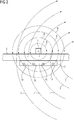
- Fig. 1 shows a section through a straight electrical line 5 arranged on a first surface 31 of a printed circuit board 3 in the form of a busbar with a square cross section, along the longitudinal axis of which an electrical current flows, caused by a voltage difference applied to the electrical line 5.
- the technical current direction ie from the electrical positive to the negative pole, is in the plane of the drawing so that the direction of rotation of the field lines 6 of the magnetic field generated by the current flow is clockwise according to the corkscrew rule.
- a current measuring module 2 is arranged on a second surface 32 of the circuit board 3, which is opposite to the first surface 31 with respect to the circuit board 3, which has four Hall sensors 1a to 1d arranged in a row across the electrical line 5 as magnetic field sensors. These Hall sensors 1a to 1d detect the Hall voltage U H occurring in the Hall sensor, which is proportional to the field strength of the magnetic field and thus proportional to the conductor current, and send the voltage values via a signal line 14 to a processing unit 12, where the strength of the in the electric current flowing in the electric line 5 is calculated.
- Fig. 2 represents, based on Fig. 1 , the case that the magnetic field 6 generated by the current flow is superimposed on an external inhomogeneous magnetic field 7, which is, for example, the earth's magnetic field or the magnetic field of a permanent magnet or which is caused by a further current-carrying line, not shown. Since the inhomogeneity of the external magnetic field 7, which is superimposed on the magnetic field 6 to be measured, ie the useful signal, is unknown, as is the case in practice, it is impossible to determine the strength of the magnetic field 6 to be measured alone. A correct indication of the strength of the electric current flowing in the electric line 5 is therefore not possible.
- an external inhomogeneous magnetic field 7 which is, for example, the earth's magnetic field or the magnetic field of a permanent magnet or which is caused by a further current-carrying line, not shown. Since the inhomogeneity of the external magnetic field 7, which is superimposed on the magnetic field 6 to be measured, ie the useful signal, is unknown, as is the case in practice
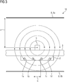
- Fig. 3 based on Fig. 1 , represents a measuring arrangement according to the invention.
- the illustrated measuring arrangement according to the invention has a filter unit 8 for homogenizing magnetic fields not caused by the electric current in the electric line 5 at the location of the magnetic field sensors 1a, 1b, 1c, 1d.
- the filter unit 8 is formed by two plate-shaped filter elements 8a and 8b, between which the electrical line 5 and the magnetic field sensors 1a, 1b, 1c, 1d are arranged.
- One of the filter elements 8a is at a distance a from the electrical line 5.
- Two adjacent magnetic field sensors 1b, 1c are at a distance b from one another, the distance a being greater than the distance b.
- Fig. 4 represents, based on Fig. 3 , represents the case that the magnetic field 6 generated by the current flow is superimposed by an external inhomogeneous magnetic field 7, which z. B. the earth's magnetic field or the magnetic field of a permanent magnet or which is caused by a further current-carrying line, not shown. Due to the filter unit, the external magnetic field 7 between the two plate-shaped filter elements 8 has homogeneous, ie parallel magnetic field lines 9 of the same magnetic field strength, ie the external magnetic field 7 is homogenized between the two plate-shaped filter elements 8.
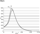
- Fig. 5 shows in an H- ⁇ r diagram with the magnetic field strength H in the unit A / m along the x-axis and the dimensionless permeability number ⁇ r along the y-axis, the curves 16, 18 of permeability numbers ⁇ r as a function of the magnetic field strength H for two exemplary ferromagnetic materials suitable for plate-shaped filter elements, namely the course 16 of the permeability number ⁇ r for the electrical sheet M 330-50 A and the curve 18 of the permeability number ⁇ r for the electrical sheet M 530-50 A, each with a sheet thickness of 0.50 mm.
- the course of the permeability number ⁇ r is roughly the same for both materials: up to a magnetic field strength H in the range of 80 or 100 A / m, the permeability number increases, reaches a maximum at 80 or 100 A / m, and decreases steadily from there from.
- the two materials were chosen because at a magnetic field strength H of 1000 A / m they still have a permeability number ⁇ r > 1000.
- Both types of electrical steel are only to be understood as examples of suitable materials and not restrictive; other ferromagnetic materials can also be used to manufacture the filter elements.
- Fig. 6 is a section through a further embodiment of a measuring arrangement according to the invention.
- a printed circuit board 3 Arranged internally in a printed circuit board 3 is a straight electrical line 5 with a square cross section, along the longitudinal axis of which an electrical current flows, caused by a voltage difference applied to the electrical line 5.
- the technical current direction ie from the electrical positive to the negative pole, is in the plane of the drawing so that the direction of rotation of the field lines 6 of the magnetic field generated by the current flow is clockwise according to the corkscrew rule.
- a current measuring module 2 is arranged on a surface 32 of the printed circuit board 3 and has four Hall sensors 1 a to 1 d arranged in a row across the electrical line 5 as magnetic field sensors. These Hall sensors 1a to 1d detect the Hall voltage U H occurring in the Hall sensor, which is proportional to the field strength of the magnetic field and thus proportional to the conductor current, and send the voltage values via a signal line 14 to a processing unit 12, where the strength of the in the electric current flowing in the electric line 5 is calculated.
- the measuring arrangement 10 has a filter unit 8 for homogenizing magnetic fields, which are not caused by the electric current in the electric line 5, at the location of the magnetic field sensors 1a, 1b, 1c, 1d.
- the filter unit 8 comprises two plate-shaped filter elements 8a and 8b, which are arranged on opposite sides of the electrical line 5 and the magnetic field sensors 1a, 1b, 1c, 1d.
- a first filter element 8a is held in position at a distance a from the electrical line 5 by a first support element 22, which is supported on the printed circuit board 3 and is fastened to the printed circuit board 3.
- a second filter element 8b is held in position by a second support element 20, which is connected to the first support element 22, at a distance a from the electrical line 5.
- the two filter elements 8a, 8b are arranged in a fixed, defined position relative to one another and relative to the printed circuit board 3, and thus also in relation to the electrical line 5 and the current measuring module 2.
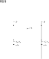
- FIGS 7 to 9 illustrate the homogenizing effect of the filter unit under the aspect of the magnetic field strength broken down into subcomponents.
- Fig. 7 shows a magnetic field 6 to be measured, which is caused by a line 5 through which current flows.
- the on Hall sensors arranged in positions 1b and 1c are aligned in such a way that they measure the magnetic field strength of the magnetic field 6 indicated by H only in a transverse direction indicated by ⁇ .
- the Hall sensor arranged at a first position 1b measures only the transverse component H b ⁇ of the magnetic field strength H b present at the first position 1 b , while the parallel component H b does not contribute to the signal of the Hall sensor.
- the Hall sensor arranged at a second position 1c measures only the transverse component H c ⁇ of the magnetic field strength H c present at the second position 1c, while the parallel component H c ⁇ does not contribute to the signal of the Hall sensor. It should be noted that due to the symmetrical positioning of the two Hall sensors, the first cross-component b H ⁇ and the second transverse component having in relation to the electrical current carrying line 5 H c ⁇ different signs.
- Fig. 8 shows an external inhomogeneous magnetic field 7, which is not caused by the current-carrying line 5, but, for example, by a permanent magnet.
- the Hall sensors arranged at positions 1b and 1c are aligned in such a way that they measure the magnetic field strength of the magnetic field 7 indicated by G only in a transverse direction indicated by ⁇ .
- the Hall sensor arranged at a first position 1b measures only the transverse component G b ⁇ of the magnetic field strength G b present at the first position 1 b , while the parallel component G b ⁇ does not contribute to the signal of the Hall sensor.
- the Hall sensor arranged at a second position 1c measures only the transverse component G c ⁇ of the magnetic field strength G c present at the second position 1 c , which due to the course of the magnetic field 7 is identical to the magnetic field strength G c .
- Fig. 9 shows an external homogenized magnetic field 9, which is generated by a filter unit from the in Fig. 8 shown inhomogeneous magnetic field 7 was created.
- the Hall sensors arranged at positions 1b and 1c are aligned in such a way that they achieve the magnetic field strength of the indicated by F Measure the magnetic field 9 only in a transverse direction indicated by ⁇ .
- the Hall sensor arranged at a first position 1b measures only the transverse component F b ⁇ of the magnetic field strength F b present at the first position 1 b , which due to the course of the magnetic field 9 is identical to the magnetic field strength F b .
- the Hall sensor arranged at a second position 1c measures only the transverse component F c ⁇ of the magnetic field strength F c present at the second position 1 c , which due to the course of the magnetic field 9 is identical to the magnetic field strength F c .
Abstract
Die Erfindung betrifft eine Messanordnung (10) zum Erfassen eines in einer elektrischen Leitung (5) fließenden elektrischen Stroms, die Messanordnung (10) umfassend- die elektrische Leitung (5),- eine Strommesseinheit (2), die wenigstens zwei Magnetfeldsensoren (1a, 1b, 1c, 1d) zum Erfassen eines durch den elektrischen Strom hervorgerufenen Magnetfelds (6) aufweist, und- eine Filtereinheit zum Homogenisieren (9) von nicht durch den elektrischen Strom hervorgerufenen Magnetfeldern (7) am Ort der Magnetfeldsensoren (1a, 1b, 1c, 1d).The invention relates to a measuring arrangement (10) for detecting an electric current flowing in an electric line (5), the measuring arrangement (10) comprising - the electric line (5), - a current measuring unit (2), the at least two magnetic field sensors (1a, 1b, 1c, 1d) for detecting a magnetic field (6) caused by the electric current, and - a filter unit for homogenizing (9) magnetic fields (7) not caused by the electric current at the location of the magnetic field sensors (1a, 1b, 1c , 1d).
Description
Die Erfindung betrifft eine Messanordnung zum Erfassen eines in einer elektrischen Leitung fließenden elektrischen Stroms. Die Erfindung betrifft außerdem ein Verfahren zum Erfassen eines in einer elektrischen Leitung fließenden elektrischen Stroms.The invention relates to a measuring arrangement for detecting an electrical current flowing in an electrical line. The invention also relates to a method for detecting an electrical current flowing in an electrical line.
In technischen Anlagen, Schaltschränken, Einschüben oder Gebäudeautomatisierungen werden Kabel oder Stromschienen zur Energieverteilung verwendet. Steigendes Umweltbewusstsein und wachsende Energiekosten erfordern eine Vermeidung von Energieverschwendung und speziell eine effiziente Nutzung elektrischer Energie. Das hierfür erforderliche Energiemanagement benötigt als Eingangsgröße eine detaillierte Überwachung der Energieverteilung. Hierbei sind insbesondere die Energieflüsse zu den an ein elektrisches Energieversorgungsnetz angeschlossenen Verbrauchern von Interesse. Um ein Energiemanagement betreiben zu können, müssen insbesondere elektrische Ströme erfasst werden, die in elektrischen Leitungen zwischen dem Energieversorgungsnetz und den Verbrauchern fließen.In technical systems, control cabinets, plug-in units or building automation systems, cables or busbars are used for power distribution. Growing environmental awareness and rising energy costs require avoidance of energy waste and, in particular, efficient use of electrical energy. The energy management required for this requires detailed monitoring of the energy distribution as an input variable. The energy flows to the consumers connected to an electrical energy supply network are of particular interest here. In order to be able to operate an energy management system, electrical currents in particular must be recorded that flow in electrical lines between the energy supply network and the consumers.
Der Erfindung liegt die Aufgabe zugrunde, eine verbesserte Messanordnung zum Erfassen eines in einer elektrischen Leitung fließenden elektrischen Stroms bereitzustellen. Der Erfindung liegt außerdem die Aufgabe zugrunde, ein verbessertes Verfahren zum Erfassen eines in einer elektrischen Leitung fließenden elektrischen Stroms bereitzustellen.The invention is based on the object of providing an improved measuring arrangement for detecting an electrical current flowing in an electrical line. The invention is also based on the object of providing an improved method for detecting an electrical current flowing in an electrical line.
Die Aufgabe, eine verbesserte Messanordnung bereitzustellen, wird gelöst durch eine Messanordnung zum Erfassen eines in einer elektrischen Leitung fließenden elektrischen Stroms, die Messanordnung umfassend die elektrische Leitung, eine Strommesseinheit, die wenigstens zwei Magnetfeldsensoren zum Erfassen eines durch den elektrischen Strom hervorgerufenen Magnetfelds aufweist, und eine Filtereinheit zum Homogenisieren von nicht durch den elektrischen Strom hervorgerufenen Magnetfeldern am Ort der Magnetfeldsensoren.The object of providing an improved measuring arrangement is achieved by a measuring arrangement for detecting an electrical current flowing in an electrical line, the measuring arrangement comprising the electrical line, a current measuring unit which has at least two magnetic field sensors for detecting a magnetic field caused by the electrical current, and a filter unit for homogenizing magnetic fields not caused by the electric current at the location of the magnetic field sensors.
Die Messanordnung dient zum Erfassen eines elektrischen Stroms, welcher durch eine elektrische Leitung fließt. Eine durch die Erfassung gewonnene Zielgröße ist die Stromstärke I des elektrischen Stroms.The measuring arrangement is used to record an electrical current which flows through an electrical line. A target variable obtained through the acquisition is the current intensity I of the electric current.
Die Messanordnung umfasst die elektrische Leitung, z.B. ein Stromkabel, eine auf einer Leiterplatte, z.B. einem PCB (= Printed Circuit Board), angeordnete Leiterbahn oder eine Stromschiene.The measuring arrangement comprises the electrical line, e.g. a power cord, one on a circuit board, e.g. a PCB (= Printed Circuit Board), arranged conductor track or a power rail.
Die Messanordnung umfasst eine Strommesseinheit, die wenigstens zwei Magnetfeldsensoren zum Erfassen eines durch den elektrischen Strom hervorgerufenen Magnetfelds aufweist. Jeder elektrische Strom erzeugt ein ihn umgebendes Magnetfeld: Um eine elektrische Leitung bildet sich bei geschlossenem Stromkreis ein Magnetfeld. Das Magnetfeld wirkt hierbei senkrecht zur stromführenden Leitung selbst. Die Feldlinien ordnen sich kreisförmig um die Leitung an, die den Mittelpunkt des Magnetfeldes bildet.The measuring arrangement comprises a current measuring unit which has at least two magnetic field sensors for detecting a magnetic field caused by the electric current. Every electrical current generates a surrounding magnetic field: a magnetic field is formed around an electrical line when the circuit is closed. The magnetic field acts perpendicular to the current-carrying line itself. The field lines are arranged in a circle around the line that forms the center of the magnetic field.
Als Magnetfeldsensor kann ein beliebiger magnetisch empfindliche Sensor dienen, insbesondere ein Sensor, welcher auf mindestens einem der folgenden Effekte basiert: Hall-Effekt, AMR (= Anisotroper Magneto-Resistiver Effekt), GMR (= Giant Magneto-Resistance).Any magnetically sensitive sensor can serve as a magnetic field sensor, in particular a sensor which is based on at least one of the following effects: Hall effect, AMR (= Anisotropic Magneto-Resistive Effect), GMR (= Giant Magneto-Resistance).
Die Messanordnung umfasst außerdem eine Filtereinheit zum Homogenisieren von externen Magnetfeldern, d.h. von Magnetfeldern, welche nicht durch den durch die elektrische Leitung fließenden elektrischen Strom hervorgerufen werden, am Ort der Magnetfeldsensoren. Homogene Magnetfelder haben analog zu homogenen elektrischen Feldern die Eigenschaft, dass sie an jedem Ort gleich stark und gleichgerichtet sind. Gibt es zwischen zwei Punkten eines Magnetfelds weder eine Flussänderung noch einen Feldstärkenunterschied und ist es ein gleichbleibendes Feld, dessen Feldlinien allesamt parallel in dieselbe Richtung verlaufen, spricht man von einem homogenen Magnetfeld.The measuring arrangement also comprises a filter unit for homogenizing external magnetic fields, i. of magnetic fields, which are not caused by the electric current flowing through the electrical line, at the location of the magnetic field sensors. Similar to homogeneous electric fields, homogeneous magnetic fields have the property that they are equally strong and in the same direction at every location. If there is neither a change in flux nor a difference in field strength between two points of a magnetic field and if the field is constant, the field lines of which all run parallel in the same direction, one speaks of a homogeneous magnetic field.
Die Aufgabe, ein verbessertes Verfahren bereitzustellen, wird gelöst durch ein Verfahren zum Erfassen eines in einer elektrischen Leitung fließenden elektrischen Stroms, wobei wenigstens zwei Magnetfeldsensoren im Bereich eines Magnetfelds, welches durch den elektrischen Strom hervorgerufen wird, angeordnet werden; wobei nicht durch den elektrischen Strom hervorgerufene externe Magnetfelder am Ort der Magnetfeldsensoren homogenisiert werden; wobei das durch den elektrischen Strom hervorgerufene Magnetfeld und die diesem überlagerten homogenisierten Magnetfelder mithilfe der Magnetfeldsensoren erfasst werden; und wobei aus den Messsignalen der Magnetfeldsensoren die Stärke des elektrischen Stroms bestimmt wird.The object of providing an improved method is achieved by a method for detecting an electrical current flowing in an electrical line, at least two magnetic field sensors being arranged in the area of a magnetic field which is caused by the electrical current; with external magnetic fields not caused by the electric current being homogenized at the location of the magnetic field sensors; wherein the magnetic field caused by the electric current and the homogenized magnetic fields superimposed on it are detected with the aid of the magnetic field sensors; and wherein the strength of the electrical current is determined from the measurement signals of the magnetic field sensors.
Das Verfahren dient zum Erfassen eines in einer elektrischen Leitung fließenden elektrischen Stroms. Dabei werden wenigstens zwei Magnetfeldsensoren im Bereich eines Magnetfelds, welches durch den elektrischen Strom hervorgerufen wird, angeordnet. Externe Magnetfelder, welche nicht durch den elektrischen Strom hervorgerufen werden, werden so beeinflusst, dass sie am Ort der Magnetfeldsensoren als homogene Magnetfelder vorliegen. Das durch den elektrischen Strom hervorgerufene Magnetfeld und die diesem überlagerten homogenisierten Magnetfelder werden mithilfe der Magnetfeldsensoren erfasst. Schließlich wird aus den Messsignalen der Magnetfeldsensoren die Stärke des elektrischen Stroms bestimmt.The method is used to detect an electrical current flowing in an electrical line. Be there at least two magnetic field sensors are arranged in the area of a magnetic field which is caused by the electric current. External magnetic fields, which are not caused by the electric current, are influenced in such a way that they are present as homogeneous magnetic fields at the location of the magnetic field sensors. The magnetic field caused by the electric current and the homogenized magnetic fields superimposed on it are recorded with the aid of the magnetic field sensors. Finally, the strength of the electrical current is determined from the measurement signals from the magnetic field sensors.
Der Erfindung liegt die Erkenntnis zugrunde, dass es mit wirtschaftlich vertretbarem Aufwand nicht möglich ist, ein oder mehrere externe Magnetfelder vollständig aus der Messanordnung am Ort der Magnetfeldsensoren zu verdrängen. Falls das oder die externen Magnetfelder vollständig aus der Messanordnung am Ort der Magnetfeldsensoren verdrängt werden könnten, dann würde ein einziger Magnetfeldsensor zum Erfassen eines durch den elektrischen Strom hervorgerufenen Magnetfelds ausreichen, da in diesem Fall nur eine unbekannte Variable existierte: das zu messende Magnetfeld, welches durch den durch die elektrische Leitung fließenden elektrischen Strom hervorgerufen wird. Da es aber mit wirtschaftlich vertretbarem Aufwand nicht möglich ist, das oder die externen Magnetfelder vollständig aus der Messanordnung am Ort der Magnetfeldsensoren zu verdrängen, basiert die vorliegende Erfindung darauf, das oder die externen Magnetfelder mittels der Filtereinheit möglichst homogen zu machen. Da das oder die externen Magnetfelder nicht verdrängt, sondern homogenisiert werden, existieren am Ort der Magnetfeldsensor zwei sich überlagernde Magnetfelder: (a) das zu messende Magnetfeld, welches durch den durch die elektrische Leitung fließenden elektrischen Strom hervorgerufen wird, und (b) das oder die externen Magnetfelder, welche als Störfelder wirken. Da somit zwei unbekannte Variable, nämlich zwei Magnetfelder unterschiedlichen Ursprungs, existieren, werden mindestens zwei Magnetfeldsensor benötigt, damit das zu messende Magnetfeld von den externen Magnetfeldern unterschieden und ermittelt werden kann, z.B. mithilfe eines Algorithmus in einer Recheneinheit herausgerechnet werden kann. Durch diesen erfindungsgemäßen Aufbau wird erreicht, dass störende externe inhomogene Magnetfelder, z. B. in Form von Kreisbögen oder andersartig verzerrten Feldern, am Ort der Magnetfeldsensoren homogenisiert werden. Im Gegensatz zum klassischen elektrischen Feld wird das störende externe Magnetfeld nicht von der Messanordnung abgeleitet oder abgeschirmt, sondern in dieser homogenisierten Form durch die Messanordnung geleitet.The invention is based on the knowledge that it is not possible with an economically justifiable effort to completely displace one or more external magnetic fields from the measuring arrangement at the location of the magnetic field sensors. If the external magnetic field (s) could be completely displaced from the measuring arrangement at the location of the magnetic field sensors, then a single magnetic field sensor would be sufficient to detect a magnetic field caused by the electric current, since in this case only one unknown variable existed: the magnetic field to be measured, which caused by the electric current flowing through the electric line. However, since it is not possible with an economically justifiable effort to completely displace the external magnetic field or fields from the measuring arrangement at the location of the magnetic field sensors, the present invention is based on making the external magnetic field or fields as homogeneous as possible using the filter unit. Since the external magnetic field or fields are not displaced, but homogenized, there are two superimposed magnetic fields at the location of the magnetic field sensor: (a) the magnetic field to be measured, which is caused by the electric current flowing through the electrical line, and (b) the or the external magnetic fields, which act as interference fields. Since there are two unknown variables, namely two magnetic fields of different origin, at least two magnetic field sensors are required so that the magnetic field to be measured can be distinguished from the external magnetic fields can be determined, for example, can be calculated using an algorithm in a computing unit. This structure according to the invention ensures that disruptive external inhomogeneous magnetic fields, e.g. B. in the form of arcs or otherwise distorted fields, are homogenized at the location of the magnetic field sensors. In contrast to the classic electric field, the interfering external magnetic field is not diverted or shielded from the measuring arrangement, but is instead passed through the measuring arrangement in this homogenized form.
Ein inhomogenes externes Magnetfeld liefert an jedem Ort des zu messenden Magnetfelds, d.h. desjenigen Magnetfelds, welches durch den durch die elektrische Leitung fließenden elektrischen Strom hervorgerufen wird, einen unterschiedlichen Beitrag zum resultierenden Magnetfeld, welches sich aus der Überlagerung des externen Magnetfelds und des zu messenden Magnetfelds ergibt. Das zu messende Magnetfeld wird also signifikant verfälscht, ohne dass eine einfache Korrektur der Messwerte möglich wäre. Ein homogenes externes Magnetfeld dagegen liefert an jedem Ort des zu messenden Magnetfelds den gleichen Beitrag zum resultierenden Magnetfeld. Das externe Magnetfeld führt also an jedem Ort des zu messenden Magnetfelds nur zu einem konstanten Offset der Feldstärke des zu messenden Magnetfelds. Somit ist eine einfache Korrektur der Messwerte der Magnetfeldsensoren möglich, einfach indem der konstante Offset, der von dem externen Magnetfeld herrührt, von den Messwerten abgezogen wird.An inhomogeneous external magnetic field delivers at every location of the magnetic field to be measured, i.e. that magnetic field that is caused by the electric current flowing through the electrical line makes a different contribution to the resulting magnetic field, which results from the superposition of the external magnetic field and the magnetic field to be measured. The magnetic field to be measured is thus significantly falsified without a simple correction of the measured values being possible. A homogeneous external magnetic field, on the other hand, makes the same contribution to the resulting magnetic field at every location of the magnetic field to be measured. The external magnetic field therefore only leads to a constant offset of the field strength of the magnetic field to be measured at every location of the magnetic field to be measured. A simple correction of the measured values of the magnetic field sensors is thus possible, simply by subtracting the constant offset that originates from the external magnetic field from the measured values.
Durch die erfindungsgemäße Messanordnung wird vermieden, dass bei einer auf einer Magnetfeldmessung basierenden Strommessung störende externe Magnetfelder, d. h. nicht von dem zu messenden Strom hervorgerufenen Magnetfelder, mitgemessen werden und so die Strommessung verfälscht wird. Als störende externe Magnetfelder sind zum Beispiel das Erdmagnetfeld, Magnetfelder von in der Umgebung der elektrischen Leitung angeordneten Permanentmagneten oder Magnetfelder von in der Umgebung der elektrischen Leitung verlaufenden weiteren elektrischen Strömen anzuführen. Die von den elektrischen Feldern bekannten Schirmkonzepte können nicht auf DC-Anwendungen übertragen werden, da bei DC-Anwendungen keine Ableitung nach Erde möglich ist (DC = Direct Current). Diese Probleme treten bei Geräten auf, welche Ströme auf Grund magnetischen Feldern messen.The measuring arrangement according to the invention prevents interfering external magnetic fields, ie magnetic fields not caused by the current to be measured, from also being measured in a current measurement based on a magnetic field measurement and thus the current measurement is falsified. The interfering external magnetic fields include, for example, the earth's magnetic field, magnetic fields from permanent magnets arranged in the vicinity of the electrical line, or magnetic fields from further electrical currents running in the vicinity of the electrical line. The ones from the electric ones Shielding concepts known to fields cannot be transferred to DC applications, since in DC applications it is not possible to discharge them to earth (DC = Direct Current). These problems occur with devices that measure currents based on magnetic fields.
Die erfindungsgemäße Messanordnung verzichtet auf eine Abschirmung störender externer Magnetfelder mithilfe eines geschlossenen Gehäuses aus Metall, da die Abschirmung viele Probleme mit sich bringt: Bei der Montage von metallischen Abschirmgehäusen kann es sein, dass elektrische Leitungen, Platinen, Leiterplatten oder andere Geräteteile durch das Abschirmgehäuse hindurch geführt werden müssen. Öffnungen schwächen aber die Schirmung und scharfe Kanten führen zu hohen Feldern und können die Filterung bzw. Schirmung aushebeln. Weiterhin können bei geschlossenen Gehäusen Spannungsabstände und ESD-Vorschriften in vielen Fällen nicht eingehalten werden (ESD = Electro-Static Discharge). Die erfindungsgemäße Messanordnung umgeht durch einen Verzicht auf schwer durchführbare und aufwändige konstruktive Lösungen alle diese Probleme.The measuring arrangement according to the invention dispenses with the shielding of interfering external magnetic fields with the aid of a closed housing made of metal, since the shielding brings many problems with it: When assembling metallic shielding housings, electrical lines, circuit boards, printed circuit boards or other device parts can pass through the shielding housing must be guided. However, openings weaken the shielding and sharp edges lead to high fields and can break out the filtering or shielding. Furthermore, with closed housings, voltage clearances and ESD regulations cannot be complied with in many cases (ESD = Electro-Static Discharge). The measuring arrangement according to the invention avoids all these problems by dispensing with difficult to implement and complex structural solutions.
Vorteilhafte Ausgestaltungen und Weiterbildungen der Erfindung sind in den abhängigen Ansprüchen angegeben. Dabei kann das erfindungsgemäße Verfahren auch entsprechend den abhängigen Vorrichtungsansprüchen weitergebildet sein, und umgekehrt.Advantageous refinements and developments of the invention are given in the dependent claims. The method according to the invention can also be developed in accordance with the dependent device claims, and vice versa.
Gemäß einer bevorzugten Ausgestaltung der Erfindung weist die Filtereinheit zwei Filterelemente auf, zwischen denen die elektrische Leitung und die Magnetfeldsensoren angeordnet sind. Vorzugsweise sind die Filterelemente flach, d.h. plan. Falls die Filterelemente nicht plan wären, sondern z.B. konvex oder konkav gewölbt, würde das "homogenisierte" Magnetfeld zwischen den beiden Filterelementen nicht mehr völlig homogen sein. Vorzugsweise sind die Filterelemente flächig: Flächige Filterelemente sind konstruktiv am einfachsten und am effektivsten. Aber dabei müssen die Filterelemente nicht als geschlossene Platten ausgebildet sein, sondern es ist zulässig, dass die Filterelemente Gitter oder Löcher, analog zu einem Faraday-Käfig, aufweisen.According to a preferred embodiment of the invention, the filter unit has two filter elements, between which the electrical line and the magnetic field sensors are arranged. The filter elements are preferably flat, ie planar. If the filter elements were not flat, but rather, for example, convex or concave, the "homogenized" magnetic field between the two filter elements would no longer be completely homogeneous. The filter elements are preferably flat: flat filter elements are structurally the simplest and most effective. But the filter elements do not have to be be designed as closed plates, but it is permissible that the filter elements have grids or holes, analogous to a Faraday cage.
Gemäß einer bevorzugten Ausgestaltung der Erfindung weisen die Filterelemente einen ferromagnetischen Werkstoff mit einer Permeabilitätszahl µr > 1 auf. Vorzugsweise weisen die Filterelemente einen ferromagnetischen Werkstoff auf, welcher bei magnetischen Feldstärke H von 1000 A/m eine Permeabilitätszahl µr > 1000 hat. Zum Beispiel bestehen die Filterelemente aus Silizium-Eisen oder aus Elektroblech M 330-50 A oder M 530-50 A gemäß DIN EN 10106:2016-03.According to a preferred embodiment of the invention, the filter elements have a ferromagnetic material with a permeability number μr> 1. The filter elements preferably have a ferromagnetic material which, at a magnetic field strength H of 1000 A / m, has a permeability number μ r > 1000. For example, the filter elements are made of silicon iron or of electrical steel M 330-50 A or M 530-50 A according to DIN EN 10106: 2016-03.
Gemäß einer bevorzugten Ausgestaltung der Erfindung weist zumindest eines der Filterelemente einen Abstand a von der elektrischen Leitung auf und weist die Strommesseinheit wenigstens zwei in einem Abstand b benachbart angeordnete Magnetfeldsensoren auf, wobei der Abstand a größer als oder gleich dem Abstand b ist. Für die Anordnung der Filterelemente gilt prinzipiell: I) Je größer der Abstand der Filterelemente von den Magnetfeldsensoren und/oder der elektrischen Leitung ist, desto weniger wird das Material der Filterelemente von dem Magnetfeld, welches von dem durch die elektrische Leitung fließenden elektrischen Strom hervorgerufen wird, beeinflusst. Wenn der Abstand a groß ist, werden mehr unerwünschte Felder homogenisiert und der unbeeinflusste Anteil des Nutzsignals, d.h. des von dem durch die elektrische Leitung fließenden elektrischen Strom hervorgerufenen Magnetfelds, wird größer. Dabei muss die Lage der Filterelemente nicht symmetrisch zu der Strommesseinheit sein. II) Je größer die seitliche Ausdehnung der Filterelemente ist, desto weniger können störende magnetische Felder "seitlich" in die Messanordnung eindringen. III) Je dicker die Filterelemente sind, desto geringer ist deren magnetische Sättigung. Im Bereich der magnetischen Sättigung nimmt die magnetische Leitfähigkeit stark ab; daher ist magnetische Sättigung bei dieser Anwendung unerwünscht.According to a preferred embodiment of the invention, at least one of the filter elements is at a distance a from the electrical line and the current measuring unit has at least two adjacent magnetic field sensors at a distance b, the distance a being greater than or equal to the distance b. The following applies in principle to the arrangement of the filter elements: I) The greater the distance between the filter elements and the magnetic field sensors and / or the electrical line, the less the material of the filter elements is affected by the magnetic field caused by the electrical current flowing through the electrical line , influenced. If the distance a is large, more undesirable fields are homogenized and the uninfluenced portion of the useful signal, ie the magnetic field caused by the electric current flowing through the electrical line, increases. The position of the filter elements does not have to be symmetrical to the current measuring unit. II) The greater the lateral expansion of the filter elements, the less disturbing magnetic fields can penetrate "laterally" into the measuring arrangement. III) The thicker the filter elements, the lower their magnetic saturation. In the area of magnetic saturation, the magnetic conductivity decreases sharply; therefore, magnetic saturation is undesirable in this application.
Gemäß einer bevorzugten Ausgestaltung der Erfindung ist die Strommesseinheit an einer Leiterplatte angeordnet. Das bietet den Vorteil, dass auch andere elektrische Bauteile und elektronische Bauteile, z.B. Kommunikationsbauteile zur Herstellung einer Kommunikationsschnittstelle für eine Übertragung von Messergebnissen, z. B. zur Übertragung in eine Cloud, einfach integriert werden können. Das bietet außerdem den Vorteil, dass eine kompakte und modulare Bauweise der Messanordnung erleichtert wird, wodurch Kosten und Bauraum eingespart werden können.According to a preferred embodiment of the invention, the current measuring unit is arranged on a printed circuit board. This offers the advantage that other electrical components and electronic components, e.g. Communication components for producing a communication interface for the transmission of measurement results, e.g. B. for transmission to a cloud, can be easily integrated. This also offers the advantage that a compact and modular construction of the measuring arrangement is facilitated, whereby costs and installation space can be saved.
Gemäß einer bevorzugten Ausgestaltung der Erfindung ist die elektrische Leitung an einer Leiterplatte angeordnet. Das bietet den Vorteil, dass eine kompakte und modulare Bauweise der Messanordnung erleichtert wird, wodurch Kosten und Bauraum eingespart werden können.According to a preferred embodiment of the invention, the electrical line is arranged on a printed circuit board. This offers the advantage that a compact and modular construction of the measuring arrangement is facilitated, whereby costs and installation space can be saved.
Gemäß einer bevorzugten Ausgestaltung der Erfindung umfasst die Strommesseinheit eine Recheneinheit, z.B. einen Prozessor, welche aus den Magnetfeld-Signalen der Magnetfeldsensoren den in der elektrischen Leitung fließenden elektrischen Strom berechnet. Vorzugsweise sind die Recheneinheit und die Strommesseinheit und/oder die elektrische Leitung an derselben Leiterplatte angeordnet. Im Falle, dass die Magnetfeldsensoren als Hall-Sensoren ausgebildet sind, liegen die Magnetfeld-Signale als Hallspannung UH vor. Das homogenisierte externe Magnetfeld liefert an jedem Ort des zu messenden Magnetfelds die gleiche Hallspannung, d.h. einen konstanten Offset der Hallspannungen, die das zu messende Magnetfeld hervorruft. Somit ist eine einfache Korrektur der von den Magnetfeldsensoren gemessenen Hallspannungen möglich, einfach indem die konstante Hallspannung, die von dem homogenisierten externen Magnetfeld herrührt, von den Hallspannungen, die von den Magnetfeldsensoren als Überlagerung des zu messenden Magnetfelds und des homogenisierten externe Magnetfelds gemessen werden, abgezogen wird. Dies ist einfach möglich, falls die Magnetfeldsensoren in Bezug auf das zu messende Magnetfeld so symmetrisch angeordnet werden, dass die Hallspannung sowohl positive als auch negative Werte annimmt.According to a preferred embodiment of the invention, the current measuring unit comprises a computing unit, for example a processor, which calculates the electrical current flowing in the electrical line from the magnetic field signals of the magnetic field sensors. The computing unit and the current measuring unit and / or the electrical line are preferably arranged on the same printed circuit board. In the event that the magnetic field sensors are designed as Hall sensors, the magnetic field signals are available as Hall voltage U H. The homogenized external magnetic field delivers the same Hall voltage at every location of the magnetic field to be measured, ie a constant offset of the Hall voltages which the magnetic field to be measured causes. A simple correction of the Hall voltages measured by the magnetic field sensors is thus possible, simply by subtracting the constant Hall voltage, which originates from the homogenized external magnetic field, from the Hall voltages, which are measured by the magnetic field sensors as a superposition of the magnetic field to be measured and the homogenized external magnetic field becomes. This is easily possible if the magnetic field sensors do so in relation to the magnetic field to be measured be arranged symmetrically so that the Hall voltage assumes both positive and negative values.
Die oben beschriebenen Eigenschaften, Merkmale und Vorteile dieser Erfindung sowie die Art und Weise, wie diese erreicht werden, werden klarer und deutlicher verständlich im Zusammenhang mit der folgenden Beschreibung der Ausführungsbeispiele, die in Verbindung mit den Zeichnungen näher erläutert werden. Hierbei zeigen in schematischer Darstellung:
- Fig. 1
- eine herkömmliche Strommesseinheit bei Fehlen eines störenden externen Magnetfelds;
- Fig. 2
- eine herkömmliche Strommesseinheit bei Anwesenheit eines störenden externen Magnetfelds;
- Fig. 3
- eine erfindungsgemäße Messanordnung bei Fehlen eines störenden externen Magnetfelds;
- Fig. 4
- eine erfindungsgemäße Messanordnung bei Anwesenheit eines störenden externen Magnetfelds;
- Fig. 5
- Verläufe von Permeabilitätszahlen für als plattenförmige Filterelemente geeignete beispielhafte ferromagnetische Werkstoffe;
- Fig. 6
- eine weitere Ausführung einer erfindungsgemäßen Messanordnung;
- Fig. 7
- ein zu messendes Magnetfeld, welches durch eine stromdurchflossene Leitung hervorgerufen wird;
- Fig. 8
- ein externes inhomogenes Magnetfeld; und
- Fig. 9
- ein durch eine Filtereinheit externes homogenisiertes Magnetfeld.
- Fig. 1
- a conventional current measuring unit in the absence of an interfering external magnetic field;
- Fig. 2
- a conventional current measuring unit in the presence of an interfering external magnetic field;
- Fig. 3
- a measuring arrangement according to the invention in the absence of an interfering external magnetic field;
- Fig. 4
- a measuring arrangement according to the invention in the presence of an interfering external magnetic field;
- Fig. 5
- Gradients of permeability numbers for exemplary ferromagnetic materials suitable as plate-shaped filter elements;
- Fig. 6
- a further embodiment of a measuring arrangement according to the invention;
- Fig. 7
- a magnetic field to be measured, which is caused by a current-carrying line;
- Fig. 8
- an external inhomogeneous magnetic field; and
- Fig. 9
- an external homogenized magnetic field through a filter unit.
Auf einer zweiten Oberfläche 32 der Leiterplatte 3, die in Bezug auf die Leiterplatte 3 entgegengesetzt zu der ersten Oberfläche 31 liegt, ist ein Strommessmodul 2 angeordnet, welches vier in einer Reihe quer zur elektrischen Leitung 5 angeordnete Hallsensoren 1a bis 1d als Magnetfeldsensoren aufweist. Diese Hallsensoren 1a bis 1d erfassen die in dem Hallsensor auftretende Hallspannung UH, welche proportional zur Feldstärke des Magnetfelds und somit proportional zum Leiterstrom ist, und senden die Spannungswerte über eine Signalleitung 14 zu einer Recheneinheit 12, wo aus den gesammelten Spannungswerten die Stärke des in der elektrischen Leitung 5 fließenden elektrischen Stroms berechnet wird.A
Durch die zwischen den beiden plattenförmigen Filterelementen 8 erzielte Homogenisierung 9 des externen Magnetfelds, welches dem zu messenden Magnetfeld 6, d.h. dem Nutzsignal, überlagert ist, ist es nun möglich, mithilfe eines in der Recheneinheit 12 installierten Algorithmus' auf Basis der Signale der Magnetfeldsensoren 1a, 1b, 1c, 1d die Stärke des zu messenden Magnetfelds 6 allein zu ermitteln. Eine korrekte Angabe der Stärke des in der elektrischen Leitung 5 fließenden elektrischen Stroms ist also nun möglich, ohne dass diese durch das externe Magnetfeld verfälscht wird.Due to the
Beide Elektroblech-Typen sind lediglich als Beispiele für geeignete Werkstoffe und nicht einschränkend zu verstehen; es sind auch andere ferromagnetische Werkstoffe zur Herstellung der Filterelemente einsetzbar.Both types of electrical steel are only to be understood as examples of suitable materials and not restrictive; other ferromagnetic materials can also be used to manufacture the filter elements.
Auf einer Oberfläche 32 der Leiterplatte 3 ist ein Strommessmodul 2 angeordnet, welches vier in einer Reihe quer zur elektrischen Leitung 5 angeordnete Hallsensoren 1a bis 1d als Magnetfeldsensoren aufweist. Diese Hallsensoren 1a bis 1d erfassen die in dem Hallsensor auftretende Hallspannung UH, welche proportional zur Feldstärke des Magnetfelds und somit proportional zum Leiterstrom ist, und senden die Spannungswerte über eine Signalleitung 14 zu einer Recheneinheit 12, wo aus den gesammelten Spannungswerten die Stärke des in der elektrischen Leitung 5 fließenden elektrischen Stroms berechnet wird.A
Die Messanordnung 10 weist eine Filtereinheit 8 zum Homogenisieren von Magnetfeldern, welche nicht durch den elektrischen Strom in der elektrischen Leitung 5 hervorgerufen werden, am Ort der Magnetfeldsensoren 1a, 1b, 1c, 1d auf. Die Filtereinheit 8 umfasst zwei plattenförmige Filterelemente 8a und 8b, welche auf entgegengesetzten Seiten der elektrischen Leitung 5 und der Magnetfeldsensoren 1a, 1b, 1c, 1d angeordnet sind. Dabei wird ein erstes Filterelement 8a von einem ersten Stützelement 22, welches sich an der Leiterplatte 3 abstützt und an der Leiterplatte 3 befestigt ist, in einem Abstand a von der elektrische Leitung 5 in Position gehalten. Ein zweites Filterelement 8b wird von einem zweiten Stützelement 20, welches mit dem ersten Stützelement 22 verbunden ist, in einem Abstand a von der elektrische Leitung 5 in Position gehalten. Auf diese Weise sind die beiden Filterelemente 8a, 8b relativ zueinander und relativ zu der Leiterplatte 3, und somit auch in Bezug auf die elektrische Leitung 5 und das Strommessmodul 2, in einer festen, definierten Position angeordnet.The measuring
Es ist zu beachten, dass aufgrund der Homogenität des Magnetfelds 9 die beiden Quer-Komponenten Fb ⊥ und Fc ⊥ gleich groß sind. Die aus einer Überlagerung der Quer-Komponenten der beiden Feldstärken H und F resultierenden Signale der Hallsensoren an den Positionen 1b, 1c können also einfach um die sich aus dem homogenisiertes Magnetfeld 9 ergebende konstante Komponente Fb ⊥ = Fc ⊥ bereinigt werden, um zu den Werten des tatsächlich zu messenden Magnetfelds 6 zu gelangen, das sich aus dem Stromfluss in der elektrischen Leitung 5 ergibt.It should be noted that due to the homogeneity of the
Claims (8)
Priority Applications (6)
| Application Number | Priority Date | Filing Date | Title |
|---|---|---|---|
| EP19174895.3A EP3739345A1 (en) | 2019-05-16 | 2019-05-16 | Detection of an electric flow in an electric circuit |
| PCT/EP2020/062806 WO2020229326A1 (en) | 2019-05-16 | 2020-05-08 | Measuring assembly for detecting a direct current |
| CN202080044039.7A CN113994219A (en) | 2019-05-16 | 2020-05-08 | Measuring device for collecting direct current |
| US17/611,721 US20230349955A1 (en) | 2019-05-16 | 2020-05-08 | Measuring assembly for detecting a direct current |
| EP20728950.5A EP3948310A1 (en) | 2019-05-16 | 2020-05-08 | Measuring assembly for detecting a direct current |
| DE112020002405.9T DE112020002405A5 (en) | 2019-05-16 | 2020-05-08 | Measuring arrangement for detecting a direct current |
Applications Claiming Priority (1)
| Application Number | Priority Date | Filing Date | Title |
|---|---|---|---|
| EP19174895.3A EP3739345A1 (en) | 2019-05-16 | 2019-05-16 | Detection of an electric flow in an electric circuit |
Publications (1)
| Publication Number | Publication Date |
|---|---|
| EP3739345A1 true EP3739345A1 (en) | 2020-11-18 |
Family
ID=66597514
Family Applications (2)
| Application Number | Title | Priority Date | Filing Date |
|---|---|---|---|
| EP19174895.3A Withdrawn EP3739345A1 (en) | 2019-05-16 | 2019-05-16 | Detection of an electric flow in an electric circuit |
| EP20728950.5A Pending EP3948310A1 (en) | 2019-05-16 | 2020-05-08 | Measuring assembly for detecting a direct current |
Family Applications After (1)
| Application Number | Title | Priority Date | Filing Date |
|---|---|---|---|
| EP20728950.5A Pending EP3948310A1 (en) | 2019-05-16 | 2020-05-08 | Measuring assembly for detecting a direct current |
Country Status (5)
| Country | Link |
|---|---|
| US (1) | US20230349955A1 (en) |
| EP (2) | EP3739345A1 (en) |
| CN (1) | CN113994219A (en) |
| DE (1) | DE112020002405A5 (en) |
| WO (1) | WO2020229326A1 (en) |
Citations (5)
| Publication number | Priority date | Publication date | Assignee | Title |
|---|---|---|---|---|
| DE20017512U1 (en) * | 2000-10-11 | 2001-02-08 | Honeywell Ag | Device for measuring current on printed circuit boards |
| WO2008030129A2 (en) * | 2006-09-06 | 2008-03-13 | Radivoje Popovic | Sensor and procedure for measuring bus bar current with skin effect correction |
| DE102010043254A1 (en) | 2010-11-03 | 2012-05-03 | Siemens Aktiengesellschaft | Measuring system for monitoring at least one phase of a system |
| US20150084617A1 (en) * | 2013-09-02 | 2015-03-26 | Senis Ag | Current Transducer For Measuring An Electrical Current |
| DE112015000490T5 (en) * | 2014-01-23 | 2016-11-10 | Denso Corporation | Current detection system |
Family Cites Families (4)
| Publication number | Priority date | Publication date | Assignee | Title |
|---|---|---|---|---|
| DE102007025505A1 (en) * | 2007-06-01 | 2008-12-04 | Epcos Ag | Arrangement for measuring a current flowing in an electrical conductor |
| DE102009029209A1 (en) * | 2009-09-04 | 2011-03-10 | Robert Bosch Gmbh | Current sensor, current measuring module and method for current measurement |
| DE102012012759A1 (en) * | 2012-06-27 | 2014-01-02 | Sensitec Gmbh | Arrangement for current measurement |
| DE102016210970A1 (en) * | 2016-06-20 | 2017-12-21 | Siemens Aktiengesellschaft | Apparatus and method for measuring the current strength of a single conductor of a multi-conductor system |
-
2019
- 2019-05-16 EP EP19174895.3A patent/EP3739345A1/en not_active Withdrawn
-
2020
- 2020-05-08 CN CN202080044039.7A patent/CN113994219A/en active Pending
- 2020-05-08 WO PCT/EP2020/062806 patent/WO2020229326A1/en active Search and Examination
- 2020-05-08 EP EP20728950.5A patent/EP3948310A1/en active Pending
- 2020-05-08 US US17/611,721 patent/US20230349955A1/en active Pending
- 2020-05-08 DE DE112020002405.9T patent/DE112020002405A5/en active Pending
Patent Citations (5)
| Publication number | Priority date | Publication date | Assignee | Title |
|---|---|---|---|---|
| DE20017512U1 (en) * | 2000-10-11 | 2001-02-08 | Honeywell Ag | Device for measuring current on printed circuit boards |
| WO2008030129A2 (en) * | 2006-09-06 | 2008-03-13 | Radivoje Popovic | Sensor and procedure for measuring bus bar current with skin effect correction |
| DE102010043254A1 (en) | 2010-11-03 | 2012-05-03 | Siemens Aktiengesellschaft | Measuring system for monitoring at least one phase of a system |
| US20150084617A1 (en) * | 2013-09-02 | 2015-03-26 | Senis Ag | Current Transducer For Measuring An Electrical Current |
| DE112015000490T5 (en) * | 2014-01-23 | 2016-11-10 | Denso Corporation | Current detection system |
Also Published As
| Publication number | Publication date |
|---|---|
| EP3948310A1 (en) | 2022-02-09 |
| CN113994219A (en) | 2022-01-28 |
| WO2020229326A1 (en) | 2020-11-19 |
| DE112020002405A5 (en) | 2022-01-27 |
| US20230349955A1 (en) | 2023-11-02 |
Similar Documents
| Publication | Publication Date | Title |
|---|---|---|
| EP1166131A1 (en) | Current meter | |
| EP1772737A2 (en) | Assembly group for the current measurement | |
| DE112016002481T5 (en) | current sensor | |
| DE102005028572B4 (en) | Current sensor arrangement with a magnetic core | |
| DE4020228A1 (en) | ARRANGEMENT FOR DETECTING A MOVING FERROMAGNETIC ELEMENT | |
| DE102007020882A1 (en) | Device for checking the attachment of a printed circuit board to a carrier | |
| DE102019109225A1 (en) | PCBA with point field detector and magnetic shielding arrangement located on the same side of a conductor | |
| DE112018000561T5 (en) | ELEMENT UNIT WITH MAGNETORESISTIVE EFFECT AND DEVICE WITH ELEMENT UNIT WITH MAGNETORESISTIVE EFFECT | |
| DE102010036040A1 (en) | Device for measuring electric current in current guard of power-electronic arrangement for industrial truck, has current guard, circuit board and magnetic field sensor that are arranged based on surface mount device construction | |
| EP3739345A1 (en) | Detection of an electric flow in an electric circuit | |
| DE102020100635A1 (en) | High-voltage connection module and converter | |
| WO2018162216A1 (en) | Current sensor arrangement and method | |
| AT510380B1 (en) | DEVICE FOR MEASURING CURRENTS IN POWER CAPACITORS | |
| DE202013010178U1 (en) | Current detection device | |
| EP3734298B1 (en) | Measuring assembly for measuring an electrical current | |
| EP2116855B1 (en) | Current measuring device | |
| DE102020117557B4 (en) | Current sensor for measuring the electrical current of a busbar | |
| EP4143587B1 (en) | Current measuring device with hall sensors | |
| EP3301436A1 (en) | Conductivity meter for measuring an electrical conductivity of a liquid medium | |
| EP4139696A1 (en) | Current sensor unit | |
| WO2002066997A1 (en) | Device, amperemeter and motor vehicle | |
| DE102021110370A1 (en) | current sensor | |
| DE102010063961A1 (en) | Arrangement for measuring current value in galvanic primary conductor, has current measuring circuit arranged on top face of circuit carrier, where edges of top and bottom faces of circuit carrier are rounded | |
| DE102008045360B4 (en) | Surface probe for alternating electrical fields in the vicinity of a magnetic field sensor | |
| DD255214A1 (en) | METHOD FOR THE TOOL-FREE MEASUREMENT OF HIGH-ENGINE, IN PARTICULAR IN ELECTRIC ENERGY PLANTS |
Legal Events
| Date | Code | Title | Description |
|---|---|---|---|
| PUAI | Public reference made under article 153(3) epc to a published international application that has entered the european phase |
Free format text: ORIGINAL CODE: 0009012 |
|
| STAA | Information on the status of an ep patent application or granted ep patent |
Free format text: STATUS: THE APPLICATION HAS BEEN PUBLISHED |
|
| AK | Designated contracting states |
Kind code of ref document: A1 Designated state(s): AL AT BE BG CH CY CZ DE DK EE ES FI FR GB GR HR HU IE IS IT LI LT LU LV MC MK MT NL NO PL PT RO RS SE SI SK SM TR |
|
| AX | Request for extension of the european patent |
Extension state: BA ME |
|
| STAA | Information on the status of an ep patent application or granted ep patent |
Free format text: STATUS: THE APPLICATION IS DEEMED TO BE WITHDRAWN |
|
| 18D | Application deemed to be withdrawn |
Effective date: 20210519 |