EP3739314B1 - Flow guiding and heat dissipating type dry block temperature calibrator - Google Patents
Flow guiding and heat dissipating type dry block temperature calibrator Download PDFInfo
- Publication number
- EP3739314B1 EP3739314B1 EP19738531.3A EP19738531A EP3739314B1 EP 3739314 B1 EP3739314 B1 EP 3739314B1 EP 19738531 A EP19738531 A EP 19738531A EP 3739314 B1 EP3739314 B1 EP 3739314B1
- Authority
- EP
- European Patent Office
- Prior art keywords
- air flow
- flow guiding
- furnace body
- fan
- gas passage
- Prior art date
- Legal status (The legal status is an assumption and is not a legal conclusion. Google has not performed a legal analysis and makes no representation as to the accuracy of the status listed.)
- Active
Links
Images




Classifications
-
- G—PHYSICS
- G01—MEASURING; TESTING
- G01K—MEASURING TEMPERATURE; MEASURING QUANTITY OF HEAT; THERMALLY-SENSITIVE ELEMENTS NOT OTHERWISE PROVIDED FOR
- G01K15/00—Testing or calibrating of thermometers
- G01K15/002—Calibrated temperature sources, temperature standards therefor
-
- G—PHYSICS
- G01—MEASURING; TESTING
- G01K—MEASURING TEMPERATURE; MEASURING QUANTITY OF HEAT; THERMALLY-SENSITIVE ELEMENTS NOT OTHERWISE PROVIDED FOR
- G01K15/00—Testing or calibrating of thermometers
- G01K15/005—Calibration
-
- H—ELECTRICITY
- H05—ELECTRIC TECHNIQUES NOT OTHERWISE PROVIDED FOR
- H05K—PRINTED CIRCUITS; CASINGS OR CONSTRUCTIONAL DETAILS OF ELECTRIC APPARATUS; MANUFACTURE OF ASSEMBLAGES OF ELECTRICAL COMPONENTS
- H05K7/00—Constructional details common to different types of electric apparatus
- H05K7/20—Modifications to facilitate cooling, ventilating, or heating
- H05K7/20009—Modifications to facilitate cooling, ventilating, or heating using a gaseous coolant in electronic enclosures
- H05K7/20209—Thermal management, e.g. fan control
Definitions
- the present invention belongs to the field of temperature calibration, and relates in particular to a dry block temperature calibrator, more specifically to a dry block temperature calibrator with a function of flow guiding and heat dissipating.
- the dry block temperature calibrator is used to calibrate thermometers or thermal switches, etc. It is widely used in industrial sites, metering places and laboratories in various industries, and has a relatively wide market.
- Existing portable dry block temperature calibrator is usually provided with a furnace body and a housing that is easy to carry.
- the furnace body includes a heat-equalizing block (furnace core), a constant temperature block with heating or/and refrigerating device, a heat insulation layer and a cooling fan.
- the heat-equalizing block has a central cavity to receive a device to be tested, such as a thermometer or thermal switch to be tested.
- the constant temperature block and the heat insulation layer are spaced apart by a certain distance to form a heat dissipation passage C1.
- An air flow generated by the cooling fan disposed at the bottom of the furnace body flows from bottom to top in the heat dissipation passage, thereby achieving cooling and heat dissipation inside the furnace body.
- the temperature of the gas flowing out of the heat dissipation passage C1 is also high, resulting in an excessive high temperature of a handle of the tested device near the furnace opening, which further causes damage to the sensors inside the handle of the tested device.
- US 2013/148687 A1 discloses a system and method for controlling a drywell including a receiver having upper and lower ends with the lower end being more insulated than the upper end having a temperature sensor in thermal contact therewith.
- CN 101639390 B relates to a vertical type thermocouple detecting furnace having a multi-section heating furnace body that mainly comprises a vertical main furnace tube and auxiliary furnace tubes, as well as a horizontal hot base.
- US 2007/289314 A1 relates to a system and method for allowing a dry well calibrator to operate over a wide range of temperatures without adversely affecting the service life of Peltier cells used in the calibration device.
- US 2009/064603 A1 relates to cooling systems for drywell calibrators, where a drywell includes a heated receiver for receiving a temperature probe, and the receiver has an inner shield positioned around the receiver to define an air channel extending between upper and lower ends of the receiver, and a flow plate positioned above the upper end to direct the air flow away from the temperature probe.
- the present invention provides a dry block temperature calibrator with a function of flow guiding and heat dissipating.
- the dry block temperature calibrator includes a housing 6 for the instrument and a furnace body 1 disposed in the housing 6, and may further include a control board 2 assembled in the housing 6 in parallel to the furnace body 1.
- the housing 6 is provided with a insertion hole 61 opposed to a furnace opening 15 of the furnace body 1, and the insertion hole 61 is configured for insertion of a device to be tested 9.
- the furnace body 1 includes a heat-equalizing block, a constant temperature block 13, and a heat insulation layer 14 disposed around the constant temperature block 13.
- a furnace base 11 is provided below the furnace body 1, and the constant temperature block 13 and the heat insulation layer 14 are disposed on the furnace base 11.
- the constant temperature block 13 surrounds the heat-equalizing block (furnace core).
- An upper end of the heat-equalizing block has an opening, that is, the furnace opening 15 for receiving the device to be tested 9.
- a heat source being in thermal contact with the heat-equalizing block.
- the heat insulation layer 14 is disposed around the constant temperature block 13, with the heat insulation layer 14 and the constant temperature block 13 being spaced apart by a certain distance to form a heat dissipation passage C1 inside the furnace body.
- the cooling fan 16 at the bottom of the furnace body 1 operates so that heat generated by the furnace core is discharged from exhaust holes above the furnace body 1 through the heat dissipation passage (the air flow inside the furnace body is shown by the fine arrows in FIG. 3 ).
- air flow generating devices for flow guiding and heat dissipating of the instrument and capable of generating a directional air flow are provided between the peripheral heat insulation layer 14 around the furnace body 1 and the housing 6.
- the air flow generating devices are located inside the housing 6 and outside the furnace body 1.
- the number of the air flow generating devices is not limited, and they can be arranged according to actual needs, provided that the locations thereof are such that the air flow generated by the air flow generating devices can act on a handle 91 of the device to be tested 9, causing the handle 91 and the sensors inside the handle 91 to be cooled down. It can be understood that a single air flow generating device may be provided on one side of the furnace body 1, or a plurality of air flow generating devices may be provided on the periphery of the furnace body 1. Further, the plurality of air flow generating devices can be arranged at regular intervals. When the furnace body 1 is a rectangular parallelepiped, the air flow generating devices may be disposed adjacent to one or more sides of the furnace body 1.
- one embodiment of the air flow generating device is a gas passage C2 communicating with a gas source.
- a gas source there are one or more of the gas passages, which are arranged at the periphery of the furnace body 1.
- the form of the gas passage C2 is not limited, as long as it can serve to guide the air flow from the gas source to the handle of the device to be tested 9. It can be understood that the gas source may be the cooling fan 16 at the bottom of the furnace body, or may be a natural air flow outside the furnace body.
- a bottom end of the gas passage C2 is provided with an air inlet communicating with the air source so that an air flow enters the gas passage C2.
- a top end of the gas passage C2 is provided with an air outlet so that the air flow flows through the air outlet to the handle 91 of the device to be tested 9.
- the gas passage C2 may be formed as a rectangular parallelepiped cylinder enclosed by four rectangular plates, or a round cylinder or a long duct. When there are a plurality of gas passages C2, they may communicate with each other, and each of the air outlets of all the gas passages C2 is directed toward the handle 91 of the device to be tested 9, or alternatively, all the gas passages may have only one air outlet provided to direct toward the handle 91 of the device to be tested 9.
- the gas passage C2 is a vertical rectangular parallelepiped passage enclosed by the control board 2 and a control board bracket 22.
- the control board bracket 22 is of a rectangular groove structure enclosed by three long rectangular plates, a side opening of which is partially closed by the control board 2, leaving the upper and lower openings unclosed.
- the gas passage C2 guides the air flow generated by the cooling fan 16 located below the furnace body from below the furnace body to the handle 91 of the device to be tested 9.
- the cooling fan 16 is located in the cavity of the furnace base 11, and the side wall of the furnace base 11 adjacent to the gas passage C2 is provided with a plurality of vents to allow the air flow generated by the cooling fan 16 to enter the gas passage C2 through the air inlet at the bottom end of the gas passage C2.
- a gas passage C3 is formed between the bottom of the furnace body 1 and the furnace base 11.
- the cavity at the bottom of the furnace body 1, where the cooling fan 16 is located communicates with the gas passage C2 outside the furnace body 1 through the gas passage C3.
- the air flow generated by the cooling fan 16 exits the instrument housing 6 through the gas passage C3 and the gas passage C2, and can be guided to the handle 91 of the device to be tested 9.
- the air flow generating device comprises a flow guiding fan 21.
- the flow guiding fan (21), and in an example not forming part of the invention, air pump, and a blower may be located on one or more sides of the furnace body.
- the air flow generating device comprises a flow guiding fan 21, and may be provided on one side of the furnace body. It can be understood that there may be a plurality of flow guiding fans 21 respectively provided on a plurality of sides of the furnace body, which together generate air flow to cool down the handle 91 of the device to be tested 9.
- the air flow generating device is provided on a mounting frame or a mounting plate positioned on one side of the furnace body. The height of the air flow generating device can be adjusted by changing the height of the mounting frame or the position of the mounting plate. Specifically, referring to FIG. 5 along with FIG.
- the mounting plate 23 is disposed above the control board bracket 22, and the height of the control board bracket 22 is lower than the height of the furnace body, so that the flow guiding fan 21 mounted on the mounting plate 23 is located on one side of the furnace body and is slightly lower than the height of the furnace body, thereby forming a space in the housing 6 that facilitates the operation of the flow guiding fan 21. Therefore, the air flow generated by the flow guiding fan 21 can act on the handle 91 of the device to be tested 9 to perform cooling down.
- yet another embodiment of the air flow generating device may comprise a combination of one or more of a flow guiding fan 21, an air pump, and a blower provided on one side of the furnace body and a gas passage C2.
- a mounting plate may be provided on the top, middle, or lower portion of the gas passage C2 to install the flow guiding fan 21, the air pump, and the blower.
- the gas passage C2 is a vertical rectangular parallelepiped air duct enclosed by the control board 2 and the control board bracket 22.
- the control board bracket 22 is of a rectangular groove structure enclosed by three rectangular plates, a side opening of which is partially closed by the control board 2 to form the gas passage C2.
- a top end opening of the gas passage C2 is closed by a fan mounting plate, and the flow guiding fan 21 is mounted below the fan mounting plate.
- the fan mounting plate is provided with an opening at a position corresponding to the flow guiding fan 21 to allow air flow generated by the flow guiding fan 21 and the gas passage C2 to pass therethrough.
- An air inlet at the bottom end of the gas passage C2 communicates with the air flow generated by the cooling fan 16.
- the cooling fan 16 is disposed in the cavity of the furnace base 11.
- the flow guiding fan 21 can be placed horizontally on one side of the furnace body 1, or can be inclined at a certain angle, so that the air flow generated by the flow guiding fan 21 flows more easily toward the furnace body 1.
- an inclination angle of the flow guiding fan 21 to the side of the furnace body 1 is between 0 degree and 90 degree, so that the fan surface of the flow guiding fan 21 faces the furnace body 1 even more.
- the above described air flow generating device may have the flow guiding fan 21 replaced with an air pump and a blower.
- the speed of the flow guiding fan 21, and the operating power of the air pump and the blower may be adjusted according to actual needs, so as to generate different air amounts to achieve different cooling effects for the handle of the device to be tested 9.
- a housing base 5 is further provided below the housing 6.
- the housing base 5 and the housing 6 are fitted vertically with each other to form a detachable housing structure, thereby facilitating maintenance and replacement of internal components of the dry block temperature calibrator.
- a vent is provided below the housing base 5 to allow external air or gas sources to enter the interior of the dry block temperature calibrator.
- the dry block temperature calibrator of the present invention may further include a measurement board module 4 and a system board module 3 disposed inside the housing 6.
- the measurement board module 4 is used for connection to a measurement line to realize the electrical measurement function of the dry block temperature calibrator, and the system board module 3 is used for parameter setting and data display to realize human-machine interaction.
- the operating principle of the flow guiding and heat dissipating type dry block temperature calibrator provided by the present invention is as follows: the air flow generated by the air flow generation device flows around the temperature calibrator, so that a part of the air flow flows in a direction toward the handle of the device to be tested.
- the part of the air flow is of a normal temperature, thereby reducing the high temperature of the handle of the device to be tested near the opening of the furnace core (the heat-equalizing block), and also causing the hot air flow around the handle of the device to be tested blown away from the furnace body by the air flow generated by the air flow generating device, and thus reducing the temperature of the handle of the device to be tested.
- the flow guiding fan 21 and the gas passages work together.
- the speed of the flow guiding fan is 6000 rpm
- the temperature of the handle of the device to be tested is reduced from 133 degree to 61 degree
- the speed of the flow guiding fan is 8000 rpm
- the temperature of the handle is further reduced to 48 degree.
- the air flow generating device proposed by the present invention is applicable to any one of existing or various newly developed temperature calibrators, furnace bodies, etc.
Landscapes
- Physics & Mathematics (AREA)
- General Physics & Mathematics (AREA)
- Engineering & Computer Science (AREA)
- Microelectronics & Electronic Packaging (AREA)
- Thermal Sciences (AREA)
- Testing Of Individual Semiconductor Devices (AREA)
- Measuring Temperature Or Quantity Of Heat (AREA)
Description
- The present invention belongs to the field of temperature calibration, and relates in particular to a dry block temperature calibrator, more specifically to a dry block temperature calibrator with a function of flow guiding and heat dissipating.
- The dry block temperature calibrator is used to calibrate thermometers or thermal switches, etc. It is widely used in industrial sites, metering places and laboratories in various industries, and has a relatively wide market.
- Existing portable dry block temperature calibrator is usually provided with a furnace body and a housing that is easy to carry. The furnace body includes a heat-equalizing block (furnace core), a constant temperature block with heating or/and refrigerating device, a heat insulation layer and a cooling fan. The heat-equalizing block has a central cavity to receive a device to be tested, such as a thermometer or thermal switch to be tested. The constant temperature block and the heat insulation layer are spaced apart by a certain distance to form a heat dissipation passage C1. An air flow generated by the cooling fan disposed at the bottom of the furnace body flows from bottom to top in the heat dissipation passage, thereby achieving cooling and heat dissipation inside the furnace body. However, due to the relative high temperature inside the furnace body, the temperature of the gas flowing out of the heat dissipation passage C1 is also high, resulting in an excessive high temperature of a handle of the tested device near the furnace opening, which further causes damage to the sensors inside the handle of the tested device.
- For instance,
US 2013/148687 A1 discloses a system and method for controlling a drywell including a receiver having upper and lower ends with the lower end being more insulated than the upper end having a temperature sensor in thermal contact therewith.CN 101639390 B relates to a vertical type thermocouple detecting furnace having a multi-section heating furnace body that mainly comprises a vertical main furnace tube and auxiliary furnace tubes, as well as a horizontal hot base.US 2007/289314 A1 relates to a system and method for allowing a dry well calibrator to operate over a wide range of temperatures without adversely affecting the service life of Peltier cells used in the calibration device. In addition,US 2009/064603 A1 relates to cooling systems for drywell calibrators, where a drywell includes a heated receiver for receiving a temperature probe, and the receiver has an inner shield positioned around the receiver to define an air channel extending between upper and lower ends of the receiver, and a flow plate positioned above the upper end to direct the air flow away from the temperature probe. - It is therefore an object of the present invention to provide a dry block temperature calibrator with a function of flow guiding and heat dissipating in view of the above defects according to claim 1. Embodiments of the present invention are defined by the dependent claims.
-
-
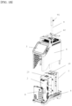
FIG. 1A is an exploded view of the components of a flow guiding and heat dissipating type dry block temperature calibrator (a low temperature furnace) according to the present invention; -
FIG. 1B is an exploded view of the components of a flow guiding and heat dissipating type dry block temperature calibrator (a high temperature furnace) according to the present invention; -
FIG. 2 is a schematic diagram of the structure of the furnace body according to the present invention; -
FIG. 3 is a schematic diagram of an air flow generating device according to the present invention, which is a gas passage and a fan in combination; -
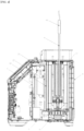
FIG. 4 is a schematic cross-sectional view of the flow guiding and heat dissipating type dry block temperature calibrator according to the present invention; and -
FIG. 5 is a perspective view of the air flow generating device according to the present invention, which is a flow guiding fan mounted on the control board bracket. - The present invention provides a dry block temperature calibrator with a function of flow guiding and heat dissipating. Referring first to
FIGS. 1A and1B , the dry block temperature calibrator includes a housing 6 for the instrument and a furnace body 1 disposed in the housing 6, and may further include acontrol board 2 assembled in the housing 6 in parallel to the furnace body 1. The housing 6 is provided with ainsertion hole 61 opposed to a furnace opening 15 of the furnace body 1, and theinsertion hole 61 is configured for insertion of a device to be tested 9. - As illustrated in
FIGS. 2 and3 , the furnace body 1 includes a heat-equalizing block, aconstant temperature block 13, and aheat insulation layer 14 disposed around theconstant temperature block 13. Afurnace base 11 is provided below the furnace body 1, and theconstant temperature block 13 and theheat insulation layer 14 are disposed on thefurnace base 11. Within a lower cavity of thefurnace base 11 there is mounted acooling fan 16. Theconstant temperature block 13 surrounds the heat-equalizing block (furnace core). An upper end of the heat-equalizing block has an opening, that is, the furnace opening 15 for receiving the device to be tested 9. Inside theconstant temperature block 13 there is also included a heat source being in thermal contact with the heat-equalizing block. Theheat insulation layer 14 is disposed around theconstant temperature block 13, with theheat insulation layer 14 and theconstant temperature block 13 being spaced apart by a certain distance to form a heat dissipation passage C1 inside the furnace body. When the temperature of the furnace body 1 needs to be lowered, thecooling fan 16 at the bottom of the furnace body 1 operates so that heat generated by the furnace core is discharged from exhaust holes above the furnace body 1 through the heat dissipation passage (the air flow inside the furnace body is shown by the fine arrows inFIG. 3 ). - In the present invention, air flow generating devices for flow guiding and heat dissipating of the instrument and capable of generating a directional air flow are provided between the peripheral
heat insulation layer 14 around the furnace body 1 and the housing 6. The air flow generating devices are located inside the housing 6 and outside the furnace body 1. - The number of the air flow generating devices is not limited, and they can be arranged according to actual needs, provided that the locations thereof are such that the air flow generated by the air flow generating devices can act on a
handle 91 of the device to be tested 9, causing thehandle 91 and the sensors inside thehandle 91 to be cooled down. It can be understood that a single air flow generating device may be provided on one side of the furnace body 1, or a plurality of air flow generating devices may be provided on the periphery of the furnace body 1. Further, the plurality of air flow generating devices can be arranged at regular intervals. When the furnace body 1 is a rectangular parallelepiped, the air flow generating devices may be disposed adjacent to one or more sides of the furnace body 1. - In a first instance, one embodiment of the air flow generating device is a gas passage C2 communicating with a gas source. As shown in
FIG. 3 , there are one or more of the gas passages, which are arranged at the periphery of the furnace body 1. The form of the gas passage C2 is not limited, as long as it can serve to guide the air flow from the gas source to the handle of the device to be tested 9. It can be understood that the gas source may be thecooling fan 16 at the bottom of the furnace body, or may be a natural air flow outside the furnace body. - Further, a bottom end of the gas passage C2 is provided with an air inlet communicating with the air source so that an air flow enters the gas passage C2. A top end of the gas passage C2 is provided with an air outlet so that the air flow flows through the air outlet to the
handle 91 of the device to be tested 9. Specifically, the gas passage C2 may be formed as a rectangular parallelepiped cylinder enclosed by four rectangular plates, or a round cylinder or a long duct. When there are a plurality of gas passages C2, they may communicate with each other, and each of the air outlets of all the gas passages C2 is directed toward thehandle 91 of the device to be tested 9, or alternatively, all the gas passages may have only one air outlet provided to direct toward thehandle 91 of the device to be tested 9. - In one embodiment, as shown in
FIG. 3 , the gas passage C2 is a vertical rectangular parallelepiped passage enclosed by thecontrol board 2 and acontrol board bracket 22. Thecontrol board bracket 22 is of a rectangular groove structure enclosed by three long rectangular plates, a side opening of which is partially closed by thecontrol board 2, leaving the upper and lower openings unclosed. The gas passage C2 guides the air flow generated by thecooling fan 16 located below the furnace body from below the furnace body to thehandle 91 of the device to be tested 9. It can be understood that thecooling fan 16 is located in the cavity of thefurnace base 11, and the side wall of thefurnace base 11 adjacent to the gas passage C2 is provided with a plurality of vents to allow the air flow generated by thecooling fan 16 to enter the gas passage C2 through the air inlet at the bottom end of the gas passage C2. For example, as shown inFIG. 3 , a gas passage C3 is formed between the bottom of the furnace body 1 and thefurnace base 11. As such, the cavity at the bottom of the furnace body 1, where thecooling fan 16 is located, communicates with the gas passage C2 outside the furnace body 1 through the gas passage C3. The air flow generated by thecooling fan 16 exits the instrument housing 6 through the gas passage C3 and the gas passage C2, and can be guided to thehandle 91 of the device to be tested 9. - According to the invention, the air flow generating device comprises a
flow guiding fan 21. The flow guiding fan (21), and in an example not forming part of the invention, air pump, and a blower may be located on one or more sides of the furnace body. - According to the invention, the air flow generating device comprises a
flow guiding fan 21, and may be provided on one side of the furnace body. It can be understood that there may be a plurality offlow guiding fans 21 respectively provided on a plurality of sides of the furnace body, which together generate air flow to cool down thehandle 91 of the device to be tested 9. In an example not forming part of the invention, the air flow generating device is provided on a mounting frame or a mounting plate positioned on one side of the furnace body. The height of the air flow generating device can be adjusted by changing the height of the mounting frame or the position of the mounting plate. Specifically, referring toFIG. 5 along withFIG. 1A , the mountingplate 23 is disposed above thecontrol board bracket 22, and the height of thecontrol board bracket 22 is lower than the height of the furnace body, so that theflow guiding fan 21 mounted on the mountingplate 23 is located on one side of the furnace body and is slightly lower than the height of the furnace body, thereby forming a space in the housing 6 that facilitates the operation of theflow guiding fan 21. Therefore, the air flow generated by theflow guiding fan 21 can act on thehandle 91 of the device to be tested 9 to perform cooling down. - In a third instance, yet another embodiment of the air flow generating device may comprise a combination of one or more of a
flow guiding fan 21, an air pump, and a blower provided on one side of the furnace body and a gas passage C2. A mounting plate may be provided on the top, middle, or lower portion of the gas passage C2 to install theflow guiding fan 21, the air pump, and the blower. In the present embodiment, as shown inFIGS. 3 and4 , the gas passage C2 is a vertical rectangular parallelepiped air duct enclosed by thecontrol board 2 and thecontrol board bracket 22. Thecontrol board bracket 22 is of a rectangular groove structure enclosed by three rectangular plates, a side opening of which is partially closed by thecontrol board 2 to form the gas passage C2. A top end opening of the gas passage C2 is closed by a fan mounting plate, and theflow guiding fan 21 is mounted below the fan mounting plate. The fan mounting plate is provided with an opening at a position corresponding to theflow guiding fan 21 to allow air flow generated by theflow guiding fan 21 and the gas passage C2 to pass therethrough. An air inlet at the bottom end of the gas passage C2 communicates with the air flow generated by the coolingfan 16. The coolingfan 16 is disposed in the cavity of thefurnace base 11. A side wall of thefurnace base 11, which is adjacent to the gas passage C2 and provided with vents, forms a gas passage C3. The air flow generated by the coolingfan 16 sequentially passes through the air passage C3, the air inlet of the gas passage C2, and the opening of the fan mounting plate to exit the housing 6. - The
flow guiding fan 21 can be placed horizontally on one side of the furnace body 1, or can be inclined at a certain angle, so that the air flow generated by theflow guiding fan 21 flows more easily toward the furnace body 1. Preferably, an inclination angle of theflow guiding fan 21 to the side of the furnace body 1 is between 0 degree and 90 degree, so that the fan surface of theflow guiding fan 21 faces the furnace body 1 even more. - It can be understood that in examples not forming part of the invention the above described air flow generating device may have the
flow guiding fan 21 replaced with an air pump and a blower. The speed of theflow guiding fan 21, and the operating power of the air pump and the blower may be adjusted according to actual needs, so as to generate different air amounts to achieve different cooling effects for the handle of the device to be tested 9. - It can be understood that a housing base 5 is further provided below the housing 6. The housing base 5 and the housing 6 are fitted vertically with each other to form a detachable housing structure, thereby facilitating maintenance and replacement of internal components of the dry block temperature calibrator. A vent is provided below the housing base 5 to allow external air or gas sources to enter the interior of the dry block temperature calibrator. The dry block temperature calibrator of the present invention may further include a measurement board module 4 and a
system board module 3 disposed inside the housing 6. The measurement board module 4 is used for connection to a measurement line to realize the electrical measurement function of the dry block temperature calibrator, and thesystem board module 3 is used for parameter setting and data display to realize human-machine interaction. - The operating principle of the flow guiding and heat dissipating type dry block temperature calibrator provided by the present invention is as follows: the air flow generated by the air flow generation device flows around the temperature calibrator, so that a part of the air flow flows in a direction toward the handle of the device to be tested. The part of the air flow is of a normal temperature, thereby reducing the high temperature of the handle of the device to be tested near the opening of the furnace core (the heat-equalizing block), and also causing the hot air flow around the handle of the device to be tested blown away from the furnace body by the air flow generated by the air flow generating device, and thus reducing the temperature of the handle of the device to be tested.
- When the air flow generating device is applied to a high temperature dry block temperature calibrator, as shown in
FIG. 1B , theflow guiding fan 21 and the gas passages work together. When the speed of the flow guiding fan is 6000 rpm, the temperature of the handle of the device to be tested is reduced from 133 degree to 61 degree, and when the speed of the flow guiding fan is 8000 rpm, the temperature of the handle is further reduced to 48 degree. - In specific implementation, the air flow generating device proposed by the present invention is applicable to any one of existing or various newly developed temperature calibrators, furnace bodies, etc.
-
- 1 furnace body
- 3 system board module
- 4 measurement board module
- 5 housing base
- 16 cooling fan
- 11 furnace base
- 13 constant temperature block
- 14 heat insulation layer
- 15 furnace opening
- 2 control board
- 21 flow guiding fan
- 22 control board bracket
- 23 mounting plate
- 6 housing
- 61 insertion hole
- 9 device to be tested
- 91 handle (device to be tested)
Claims (7)
- A dry block temperature calibrator capable of air flow guiding and heat dissipating, comprising:a housing (6) and a housing base (5);a furnace body (1) disposed in the housing (6);at least one air flow generating device disposed between the housing (6) and the furnace body (1), and configured to generate an air flow to be blown toward a handle (91) of a device to be tested (9) that remains out of the furnace body (1)
when the device to be tested (9) is inserted into the furnace body (1) for calibration; anda cooling fan (16) disposed in the housing (6) and below the furnace body (1),wherein the air flow generating device comprises:one or more gas passages C2 provided at a bottom end thereof with an air inlet configured to be in fluid communication with the cooling fan (16) or an external gas source.and at a top end thereof with an air outlet directed toward the handle of the device to be tested, and configured to guide the air flow from the air inlet to the handle of the device to be tested; characterised in that the air flow generating device further comprisesa fan (21) for flow guiding that is provided inside the gas passage C2, wherein the fan (21) for flow guiding and the gas passage are configured to generate the air flow directed toward the air outlet of the gas passage,wherein the dry block temperature calibrator further comprises a control board bracket (22) for installing a control board (2), a mounting plate (23) is mechanically fixed on a top end of the control board bracket (22), the fan (21) for flow guiding being mounted on the mounting plate (23), and a bottom end of the control board bracket (22) is fixed on the housing base (5) of the dry block temperature calibrator. - The dry block temperature calibrator capable of air flow guiding and heat dissipating according to claim 1, wherein the gas passage C2 is arranged on one side of the furnace body.
- The dry block temperature calibrator capable of air flow guiding and heat dissipating according to claim 2, wherein the gas passage C2 is a rectangular parallelepiped cylinder, a round cylinder or an air duct arranged on one side of the furnace body (1).
- The dry block temperature calibrator capable of air flow guiding and heat dissipating according to claim 3, wherein the gas passage C2 is a rectangular parallelepiped cylinder enclosed by a control board bracket (22) and a control board (2), wherein the control board bracket (22) has a side opening which is partially covered by the control board (2), and upper and lower openings which are open, and wherein the mounting plate (23) is provided at an air outlet of the rectangular parallelepiped cylinder, the fan (21) for flow guiding is mechanically fixed below the mounting plate (23), and the mounting plate (23) is provided with an opening corresponding to the position of the fan (21) for flow guiding .
- The dry block temperature calibrator capable of air flow guiding and heat dissipating according to claim 4, wherein a furnace base (11) is provided below the furnace body (1), the cooling fan (16) is disposed in a lower cavity of the furnace base (11), and at least one vent is formed on a side wall of the furnace base (11) adjacent to the gas passage to form a gas passage C3, so that the air flow generated by the cooling fan (16) flows to an air inlet below the gas passage C2.
- The dry block temperature calibrator capable of air flow guiding and heat dissipating according to claim 1, wherein a direction of the air flow generated by the fan (21) for flow guiding is vertically upward or inclined to one side of the furnace body.
- The dry block temperature calibrator capable of air flow guiding and heat dissipating according to claim 6, wherein the fan (21) for flow guiding is inclined to one side of the furnace body
Applications Claiming Priority (3)
| Application Number | Priority Date | Filing Date | Title |
|---|---|---|---|
| CN201820032127.5U CN207675335U (en) | 2018-01-09 | 2018-01-09 | Flow-guiding radiation stem body temperature checker |
| CN201810018505.9A CN110017914B (en) | 2018-01-09 | 2018-01-09 | Flow-guiding heat-dissipating dry body temperature calibrator |
| PCT/CN2019/070730 WO2019137343A1 (en) | 2018-01-09 | 2019-01-08 | Flow guiding and heat dissipating type dry block temperature calibrator |
Publications (3)
| Publication Number | Publication Date |
|---|---|
| EP3739314A1 EP3739314A1 (en) | 2020-11-18 |
| EP3739314A4 EP3739314A4 (en) | 2021-10-13 |
| EP3739314B1 true EP3739314B1 (en) | 2024-08-21 |
Family
ID=67219424
Family Applications (1)
| Application Number | Title | Priority Date | Filing Date |
|---|---|---|---|
| EP19738531.3A Active EP3739314B1 (en) | 2018-01-09 | 2019-01-08 | Flow guiding and heat dissipating type dry block temperature calibrator |
Country Status (3)
| Country | Link |
|---|---|
| US (1) | US11740139B2 (en) |
| EP (1) | EP3739314B1 (en) |
| WO (1) | WO2019137343A1 (en) |
Families Citing this family (9)
| Publication number | Priority date | Publication date | Assignee | Title |
|---|---|---|---|---|
| US11402278B2 (en) * | 2018-01-09 | 2022-08-02 | Beijing Const Instruments Technology Inc. | Low-temperature dry block temperature calibrator |
| CN110296773B (en) * | 2018-03-22 | 2020-11-03 | 北京康斯特仪表科技股份有限公司 | Method for calibrating short-branch temperature measuring equipment by using dry body temperature calibrator |
| DE102018114615A1 (en) * | 2018-06-19 | 2019-12-19 | SIKA Dr. Siebert & Kühn GmbH & Co. KG | Temperature Calibrator |
| FI129727B (en) * | 2019-10-28 | 2022-08-15 | Beamex Oy Ab | Improving, detecting and indicating stability in an industrial temperature dry block calibrator |
| FI129720B (en) * | 2019-10-28 | 2022-07-29 | Beamex Oy Ab | Velocity regulation of the calibrator block in a dry block calibrator |
| FI131042B1 (en) * | 2019-10-28 | 2024-08-13 | Beamex Oy Ab | Temperature calibrator with advanced functionality |
| US12104965B2 (en) * | 2020-08-05 | 2024-10-01 | King Nutronics, Llc | Dry well temperature calibrators, cooling systems, and methods |
| CN113432758B (en) * | 2021-06-21 | 2022-05-24 | 合肥智测电子有限公司 | Ultra-low temperature portable dry furnace using Stirling refrigerator |
| CN216385506U (en) * | 2022-02-17 | 2022-04-26 | 宁德时代新能源科技股份有限公司 | Detection device and pole piece manufacturing equipment |
Family Cites Families (22)
| Publication number | Priority date | Publication date | Assignee | Title |
|---|---|---|---|---|
| US3350915A (en) * | 1965-05-27 | 1967-11-07 | Procedyne Corp | Thermometric calibration apparatus utilizing a fluidized bed of solid particles |
| JP3352785B2 (en) * | 1993-09-24 | 2002-12-03 | 株式会社チノー | Thermometer calibration device |
| NO305295B1 (en) * | 1997-07-18 | 1999-05-03 | Instrutek Holding As | Device for calibrating temperature sensors |
| US7607309B2 (en) | 2006-06-14 | 2009-10-27 | Fluke Corporation | Temperature calibration device having reconfigurable heating/cooling modules to provide wide temperature range |
| US7785000B2 (en) * | 2007-09-11 | 2010-08-31 | Fluke Corporation | Venting system for drywell calibrators |
| US7909504B2 (en) * | 2007-11-14 | 2011-03-22 | Fluke Corporation | Open-loop vertical drywell gradient correction system and method |
| WO2010094332A1 (en) * | 2009-02-19 | 2010-08-26 | Ametek Denmark A/S | A temperature calibration device, a calibrator block, and a method for calibrating a temperature probe |
| CN101639390B (en) * | 2009-09-07 | 2011-04-27 | 上海量值测控仪器科技有限公司 | Novel vertical type thermocouple detecting furnace |
| JP5761705B2 (en) * | 2011-01-07 | 2015-08-12 | 国立研究開発法人産業技術総合研究所 | Gas circulation type variable temperature oven for temperature standard |
| CN103851912B (en) * | 2012-12-05 | 2017-09-08 | 弗卢克公司 | High temperature furnace with reconfigurable heater circuit |
| NL2011283C2 (en) * | 2013-08-08 | 2015-02-10 | Tradinco Instr App N B V | Temperature calibration arrangement and calibration oven comprising such an arrangement. |
| CN204389067U (en) | 2014-12-26 | 2015-06-10 | 上海市计量测试技术研究院 | A kind of shallow type temperature checking stove that declines |
| CN205449333U (en) * | 2016-03-15 | 2016-08-10 | 厦门瑞德利校准检测技术有限公司 | Portable temperature correction appearance |
| CN106017739A (en) * | 2016-07-28 | 2016-10-12 | 无锡信大气象传感网科技有限公司 | Temperature sensor calibration device |
| CN106248253A (en) * | 2016-07-28 | 2016-12-21 | 无锡信大气象传感网科技有限公司 | The temperature sensor calibrator (-ter) unit of uniform temperature fields |
| CN207675335U (en) | 2018-01-09 | 2018-07-31 | 北京康斯特仪表科技股份有限公司 | Flow-guiding radiation stem body temperature checker |
| EP3739312B1 (en) * | 2018-01-09 | 2023-12-20 | Beijing Const Instruments Technology Inc. | High temperature dry block temperature calibrator |
| CN207866392U (en) | 2018-01-09 | 2018-09-14 | 北京康斯特仪表科技股份有限公司 | A kind of low temperature stem body temperature checker |
| US11402278B2 (en) * | 2018-01-09 | 2022-08-02 | Beijing Const Instruments Technology Inc. | Low-temperature dry block temperature calibrator |
| CN207866391U (en) | 2018-01-09 | 2018-09-14 | 北京康斯特仪表科技股份有限公司 | High temperature stem body temperature checker |
| EP3816696A4 (en) * | 2018-06-05 | 2022-03-02 | Nittoh Inc. | TELE-LENS SYSTEM AND IMAGING DEVICE |
| CN115515396A (en) * | 2022-10-18 | 2022-12-23 | 许昌驰诚电气有限公司 | High-precision calibration equipment for household alarm |
-
2019
- 2019-01-08 EP EP19738531.3A patent/EP3739314B1/en active Active
- 2019-01-08 WO PCT/CN2019/070730 patent/WO2019137343A1/en not_active Ceased
- 2019-01-08 US US16/961,014 patent/US11740139B2/en active Active
Also Published As
| Publication number | Publication date |
|---|---|
| EP3739314A1 (en) | 2020-11-18 |
| US20210063253A1 (en) | 2021-03-04 |
| WO2019137343A1 (en) | 2019-07-18 |
| EP3739314A4 (en) | 2021-10-13 |
| US11740139B2 (en) | 2023-08-29 |
Similar Documents
| Publication | Publication Date | Title |
|---|---|---|
| US11740139B2 (en) | Flow guiding and heat dissipating type dry block temperature calibrator | |
| US7785000B2 (en) | Venting system for drywell calibrators | |
| KR101411233B1 (en) | Battery testing device | |
| CA2730080C (en) | Method and apparatus to accurately read ambient room temperature for a room sensor apparatus | |
| US10241092B2 (en) | Gas chromatograph device | |
| CN101752597A (en) | Power battery device of electric vehicle | |
| CN110017914B (en) | Flow-guiding heat-dissipating dry body temperature calibrator | |
| KR20160053948A (en) | Control console for a numerically controlled machine tool | |
| JP2022554295A (en) | gas equipment | |
| CN114614140A (en) | Energy storage container | |
| CN207675335U (en) | Flow-guiding radiation stem body temperature checker | |
| US7185503B2 (en) | Conditioning system for a manufacturing machine, in particular a machine tool | |
| CN117806430B (en) | Memory test server system and double-air-duct memory test device thereof | |
| CN207866392U (en) | A kind of low temperature stem body temperature checker | |
| CN102316699A (en) | Cooling method, and circuit board maintenance device and equipment adopting cooling equipment method | |
| JP2005044857A (en) | Cooling mechanism | |
| CN220323470U (en) | Temperature control test incubator | |
| CN212432358U (en) | Black body calibration source for microwave radiometer and microwave radiometer | |
| CN219225012U (en) | Test device | |
| CN114570625B (en) | Cooling mechanism for curing machine, curing machine and curing production line | |
| CN216696503U (en) | Automatic temperature control aging device | |
| CN212869890U (en) | Air valve assembly and temperature calibrator | |
| JP2006308368A (en) | Test chamber and method for electronic equipment | |
| CA2248518A1 (en) | Enclosure for equipment which requires cooling | |
| CN114137352A (en) | Automatic temperature control aging device |
Legal Events
| Date | Code | Title | Description |
|---|---|---|---|
| STAA | Information on the status of an ep patent application or granted ep patent |
Free format text: STATUS: THE INTERNATIONAL PUBLICATION HAS BEEN MADE |
|
| PUAI | Public reference made under article 153(3) epc to a published international application that has entered the european phase |
Free format text: ORIGINAL CODE: 0009012 |
|
| STAA | Information on the status of an ep patent application or granted ep patent |
Free format text: STATUS: REQUEST FOR EXAMINATION WAS MADE |
|
| 17P | Request for examination filed |
Effective date: 20200619 |
|
| AK | Designated contracting states |
Kind code of ref document: A1 Designated state(s): AL AT BE BG CH CY CZ DE DK EE ES FI FR GB GR HR HU IE IS IT LI LT LU LV MC MK MT NL NO PL PT RO RS SE SI SK SM TR |
|
| AX | Request for extension of the european patent |
Extension state: BA ME |
|
| DAV | Request for validation of the european patent (deleted) | ||
| DAX | Request for extension of the european patent (deleted) | ||
| A4 | Supplementary search report drawn up and despatched |
Effective date: 20210909 |
|
| RIC1 | Information provided on ipc code assigned before grant |
Ipc: H05K 7/20 20060101ALI20210903BHEP Ipc: G01K 15/00 20060101AFI20210903BHEP |
|
| STAA | Information on the status of an ep patent application or granted ep patent |
Free format text: STATUS: EXAMINATION IS IN PROGRESS |
|
| 17Q | First examination report despatched |
Effective date: 20230310 |
|
| GRAP | Despatch of communication of intention to grant a patent |
Free format text: ORIGINAL CODE: EPIDOSNIGR1 |
|
| STAA | Information on the status of an ep patent application or granted ep patent |
Free format text: STATUS: GRANT OF PATENT IS INTENDED |
|
| INTG | Intention to grant announced |
Effective date: 20240320 |
|
| GRAS | Grant fee paid |
Free format text: ORIGINAL CODE: EPIDOSNIGR3 |
|
| GRAA | (expected) grant |
Free format text: ORIGINAL CODE: 0009210 |
|
| STAA | Information on the status of an ep patent application or granted ep patent |
Free format text: STATUS: THE PATENT HAS BEEN GRANTED |
|
| AK | Designated contracting states |
Kind code of ref document: B1 Designated state(s): AL AT BE BG CH CY CZ DE DK EE ES FI FR GB GR HR HU IE IS IT LI LT LU LV MC MK MT NL NO PL PT RO RS SE SI SK SM TR |
|
| REG | Reference to a national code |
Ref country code: GB Ref legal event code: FG4D |
|
| REG | Reference to a national code |
Ref country code: CH Ref legal event code: EP |
|
| REG | Reference to a national code |
Ref country code: IE Ref legal event code: FG4D |
|
| REG | Reference to a national code |
Ref country code: DE Ref legal event code: R096 Ref document number: 602019057395 Country of ref document: DE |
|
| REG | Reference to a national code |
Ref country code: LT Ref legal event code: MG9D |
|
| REG | Reference to a national code |
Ref country code: NL Ref legal event code: MP Effective date: 20240821 |
|
| PG25 | Lapsed in a contracting state [announced via postgrant information from national office to epo] |
Ref country code: NO Free format text: LAPSE BECAUSE OF FAILURE TO SUBMIT A TRANSLATION OF THE DESCRIPTION OR TO PAY THE FEE WITHIN THE PRESCRIBED TIME-LIMIT Effective date: 20241121 |
|
| REG | Reference to a national code |
Ref country code: AT Ref legal event code: MK05 Ref document number: 1715913 Country of ref document: AT Kind code of ref document: T Effective date: 20240821 |
|
| PG25 | Lapsed in a contracting state [announced via postgrant information from national office to epo] |
Ref country code: PL Free format text: LAPSE BECAUSE OF FAILURE TO SUBMIT A TRANSLATION OF THE DESCRIPTION OR TO PAY THE FEE WITHIN THE PRESCRIBED TIME-LIMIT Effective date: 20240821 Ref country code: NL Free format text: LAPSE BECAUSE OF FAILURE TO SUBMIT A TRANSLATION OF THE DESCRIPTION OR TO PAY THE FEE WITHIN THE PRESCRIBED TIME-LIMIT Effective date: 20240821 Ref country code: FI Free format text: LAPSE BECAUSE OF FAILURE TO SUBMIT A TRANSLATION OF THE DESCRIPTION OR TO PAY THE FEE WITHIN THE PRESCRIBED TIME-LIMIT Effective date: 20240821 Ref country code: PT Free format text: LAPSE BECAUSE OF FAILURE TO SUBMIT A TRANSLATION OF THE DESCRIPTION OR TO PAY THE FEE WITHIN THE PRESCRIBED TIME-LIMIT Effective date: 20241223 Ref country code: GR Free format text: LAPSE BECAUSE OF FAILURE TO SUBMIT A TRANSLATION OF THE DESCRIPTION OR TO PAY THE FEE WITHIN THE PRESCRIBED TIME-LIMIT Effective date: 20241122 |
|
| PG25 | Lapsed in a contracting state [announced via postgrant information from national office to epo] |
Ref country code: BG Free format text: LAPSE BECAUSE OF FAILURE TO SUBMIT A TRANSLATION OF THE DESCRIPTION OR TO PAY THE FEE WITHIN THE PRESCRIBED TIME-LIMIT Effective date: 20240821 |
|
| PG25 | Lapsed in a contracting state [announced via postgrant information from national office to epo] |
Ref country code: LV Free format text: LAPSE BECAUSE OF FAILURE TO SUBMIT A TRANSLATION OF THE DESCRIPTION OR TO PAY THE FEE WITHIN THE PRESCRIBED TIME-LIMIT Effective date: 20240821 |
|
| PG25 | Lapsed in a contracting state [announced via postgrant information from national office to epo] |
Ref country code: IS Free format text: LAPSE BECAUSE OF FAILURE TO SUBMIT A TRANSLATION OF THE DESCRIPTION OR TO PAY THE FEE WITHIN THE PRESCRIBED TIME-LIMIT Effective date: 20241221 Ref country code: AT Free format text: LAPSE BECAUSE OF FAILURE TO SUBMIT A TRANSLATION OF THE DESCRIPTION OR TO PAY THE FEE WITHIN THE PRESCRIBED TIME-LIMIT Effective date: 20240821 |
|
| PG25 | Lapsed in a contracting state [announced via postgrant information from national office to epo] |
Ref country code: HR Free format text: LAPSE BECAUSE OF FAILURE TO SUBMIT A TRANSLATION OF THE DESCRIPTION OR TO PAY THE FEE WITHIN THE PRESCRIBED TIME-LIMIT Effective date: 20240821 |
|
| PG25 | Lapsed in a contracting state [announced via postgrant information from national office to epo] |
Ref country code: ES Free format text: LAPSE BECAUSE OF FAILURE TO SUBMIT A TRANSLATION OF THE DESCRIPTION OR TO PAY THE FEE WITHIN THE PRESCRIBED TIME-LIMIT Effective date: 20240821 Ref country code: RS Free format text: LAPSE BECAUSE OF FAILURE TO SUBMIT A TRANSLATION OF THE DESCRIPTION OR TO PAY THE FEE WITHIN THE PRESCRIBED TIME-LIMIT Effective date: 20241121 |
|
| PG25 | Lapsed in a contracting state [announced via postgrant information from national office to epo] |
Ref country code: RS Free format text: LAPSE BECAUSE OF FAILURE TO SUBMIT A TRANSLATION OF THE DESCRIPTION OR TO PAY THE FEE WITHIN THE PRESCRIBED TIME-LIMIT Effective date: 20241121 Ref country code: PT Free format text: LAPSE BECAUSE OF FAILURE TO SUBMIT A TRANSLATION OF THE DESCRIPTION OR TO PAY THE FEE WITHIN THE PRESCRIBED TIME-LIMIT Effective date: 20241223 Ref country code: PL Free format text: LAPSE BECAUSE OF FAILURE TO SUBMIT A TRANSLATION OF THE DESCRIPTION OR TO PAY THE FEE WITHIN THE PRESCRIBED TIME-LIMIT Effective date: 20240821 Ref country code: NO Free format text: LAPSE BECAUSE OF FAILURE TO SUBMIT A TRANSLATION OF THE DESCRIPTION OR TO PAY THE FEE WITHIN THE PRESCRIBED TIME-LIMIT Effective date: 20241121 Ref country code: NL Free format text: LAPSE BECAUSE OF FAILURE TO SUBMIT A TRANSLATION OF THE DESCRIPTION OR TO PAY THE FEE WITHIN THE PRESCRIBED TIME-LIMIT Effective date: 20240821 Ref country code: LV Free format text: LAPSE BECAUSE OF FAILURE TO SUBMIT A TRANSLATION OF THE DESCRIPTION OR TO PAY THE FEE WITHIN THE PRESCRIBED TIME-LIMIT Effective date: 20240821 Ref country code: IS Free format text: LAPSE BECAUSE OF FAILURE TO SUBMIT A TRANSLATION OF THE DESCRIPTION OR TO PAY THE FEE WITHIN THE PRESCRIBED TIME-LIMIT Effective date: 20241221 Ref country code: HR Free format text: LAPSE BECAUSE OF FAILURE TO SUBMIT A TRANSLATION OF THE DESCRIPTION OR TO PAY THE FEE WITHIN THE PRESCRIBED TIME-LIMIT Effective date: 20240821 Ref country code: GR Free format text: LAPSE BECAUSE OF FAILURE TO SUBMIT A TRANSLATION OF THE DESCRIPTION OR TO PAY THE FEE WITHIN THE PRESCRIBED TIME-LIMIT Effective date: 20241122 Ref country code: FI Free format text: LAPSE BECAUSE OF FAILURE TO SUBMIT A TRANSLATION OF THE DESCRIPTION OR TO PAY THE FEE WITHIN THE PRESCRIBED TIME-LIMIT Effective date: 20240821 Ref country code: ES Free format text: LAPSE BECAUSE OF FAILURE TO SUBMIT A TRANSLATION OF THE DESCRIPTION OR TO PAY THE FEE WITHIN THE PRESCRIBED TIME-LIMIT Effective date: 20240821 Ref country code: BG Free format text: LAPSE BECAUSE OF FAILURE TO SUBMIT A TRANSLATION OF THE DESCRIPTION OR TO PAY THE FEE WITHIN THE PRESCRIBED TIME-LIMIT Effective date: 20240821 Ref country code: AT Free format text: LAPSE BECAUSE OF FAILURE TO SUBMIT A TRANSLATION OF THE DESCRIPTION OR TO PAY THE FEE WITHIN THE PRESCRIBED TIME-LIMIT Effective date: 20240821 |
|
| PG25 | Lapsed in a contracting state [announced via postgrant information from national office to epo] |
Ref country code: DK Free format text: LAPSE BECAUSE OF FAILURE TO SUBMIT A TRANSLATION OF THE DESCRIPTION OR TO PAY THE FEE WITHIN THE PRESCRIBED TIME-LIMIT Effective date: 20240821 Ref country code: SM Free format text: LAPSE BECAUSE OF FAILURE TO SUBMIT A TRANSLATION OF THE DESCRIPTION OR TO PAY THE FEE WITHIN THE PRESCRIBED TIME-LIMIT Effective date: 20240821 Ref country code: RO Free format text: LAPSE BECAUSE OF FAILURE TO SUBMIT A TRANSLATION OF THE DESCRIPTION OR TO PAY THE FEE WITHIN THE PRESCRIBED TIME-LIMIT Effective date: 20240821 |
|
| PG25 | Lapsed in a contracting state [announced via postgrant information from national office to epo] |
Ref country code: EE Free format text: LAPSE BECAUSE OF FAILURE TO SUBMIT A TRANSLATION OF THE DESCRIPTION OR TO PAY THE FEE WITHIN THE PRESCRIBED TIME-LIMIT Effective date: 20240821 |
|
| PG25 | Lapsed in a contracting state [announced via postgrant information from national office to epo] |
Ref country code: CZ Free format text: LAPSE BECAUSE OF FAILURE TO SUBMIT A TRANSLATION OF THE DESCRIPTION OR TO PAY THE FEE WITHIN THE PRESCRIBED TIME-LIMIT Effective date: 20240821 |
|
| PG25 | Lapsed in a contracting state [announced via postgrant information from national office to epo] |
Ref country code: SK Free format text: LAPSE BECAUSE OF FAILURE TO SUBMIT A TRANSLATION OF THE DESCRIPTION OR TO PAY THE FEE WITHIN THE PRESCRIBED TIME-LIMIT Effective date: 20240821 Ref country code: IT Free format text: LAPSE BECAUSE OF FAILURE TO SUBMIT A TRANSLATION OF THE DESCRIPTION OR TO PAY THE FEE WITHIN THE PRESCRIBED TIME-LIMIT Effective date: 20240821 |
|
| REG | Reference to a national code |
Ref country code: DE Ref legal event code: R097 Ref document number: 602019057395 Country of ref document: DE |
|
| PLBE | No opposition filed within time limit |
Free format text: ORIGINAL CODE: 0009261 |
|
| STAA | Information on the status of an ep patent application or granted ep patent |
Free format text: STATUS: NO OPPOSITION FILED WITHIN TIME LIMIT |
|
| 26N | No opposition filed |
Effective date: 20250522 |
|
| REG | Reference to a national code |
Ref country code: CH Ref legal event code: PL |
|
| PG25 | Lapsed in a contracting state [announced via postgrant information from national office to epo] |
Ref country code: SE Free format text: LAPSE BECAUSE OF FAILURE TO SUBMIT A TRANSLATION OF THE DESCRIPTION OR TO PAY THE FEE WITHIN THE PRESCRIBED TIME-LIMIT Effective date: 20240821 |
|
| PG25 | Lapsed in a contracting state [announced via postgrant information from national office to epo] |
Ref country code: MC Free format text: LAPSE BECAUSE OF FAILURE TO SUBMIT A TRANSLATION OF THE DESCRIPTION OR TO PAY THE FEE WITHIN THE PRESCRIBED TIME-LIMIT Effective date: 20240821 Ref country code: LU Free format text: LAPSE BECAUSE OF NON-PAYMENT OF DUE FEES Effective date: 20250108 |
|
| PG25 | Lapsed in a contracting state [announced via postgrant information from national office to epo] |
Ref country code: BE Free format text: LAPSE BECAUSE OF NON-PAYMENT OF DUE FEES Effective date: 20250131 |
|
| PG25 | Lapsed in a contracting state [announced via postgrant information from national office to epo] |
Ref country code: FR Free format text: LAPSE BECAUSE OF NON-PAYMENT OF DUE FEES Effective date: 20250131 |
|
| PG25 | Lapsed in a contracting state [announced via postgrant information from national office to epo] |
Ref country code: CH Free format text: LAPSE BECAUSE OF NON-PAYMENT OF DUE FEES Effective date: 20250131 |
|
| REG | Reference to a national code |
Ref country code: BE Ref legal event code: MM Effective date: 20250131 |
|
| PG25 | Lapsed in a contracting state [announced via postgrant information from national office to epo] |
Ref country code: IE Free format text: LAPSE BECAUSE OF NON-PAYMENT OF DUE FEES Effective date: 20250108 |
|
| PGFP | Annual fee paid to national office [announced via postgrant information from national office to epo] |
Ref country code: GB Payment date: 20260106 Year of fee payment: 8 |
|
| PGFP | Annual fee paid to national office [announced via postgrant information from national office to epo] |
Ref country code: DE Payment date: 20251230 Year of fee payment: 8 |