EP3739275A1 - Air sweeping mechanism and air conditioner having same - Google Patents
Air sweeping mechanism and air conditioner having same Download PDFInfo
- Publication number
- EP3739275A1 EP3739275A1 EP18898368.8A EP18898368A EP3739275A1 EP 3739275 A1 EP3739275 A1 EP 3739275A1 EP 18898368 A EP18898368 A EP 18898368A EP 3739275 A1 EP3739275 A1 EP 3739275A1
- Authority
- EP
- European Patent Office
- Prior art keywords
- air sweeping
- driving
- section
- air
- blade
- Prior art date
- Legal status (The legal status is an assumption and is not a legal conclusion. Google has not performed a legal analysis and makes no representation as to the accuracy of the status listed.)
- Pending
Links
- 238000010408 sweeping Methods 0.000 title claims abstract description 154
- 230000007246 mechanism Effects 0.000 title claims abstract description 66
- 238000000034 method Methods 0.000 description 7
- 238000010586 diagram Methods 0.000 description 6
- 238000009434 installation Methods 0.000 description 3
- 230000000694 effects Effects 0.000 description 2
- 230000004048 modification Effects 0.000 description 2
- 238000012986 modification Methods 0.000 description 2
- 230000000712 assembly Effects 0.000 description 1
- 238000000429 assembly Methods 0.000 description 1
- 230000015572 biosynthetic process Effects 0.000 description 1
Images


Classifications
-
- F—MECHANICAL ENGINEERING; LIGHTING; HEATING; WEAPONS; BLASTING
- F24—HEATING; RANGES; VENTILATING
- F24F—AIR-CONDITIONING; AIR-HUMIDIFICATION; VENTILATION; USE OF AIR CURRENTS FOR SCREENING
- F24F13/00—Details common to, or for air-conditioning, air-humidification, ventilation or use of air currents for screening
- F24F13/08—Air-flow control members, e.g. louvres, grilles, flaps or guide plates
- F24F13/10—Air-flow control members, e.g. louvres, grilles, flaps or guide plates movable, e.g. dampers
- F24F13/14—Air-flow control members, e.g. louvres, grilles, flaps or guide plates movable, e.g. dampers built up of tilting members, e.g. louvre
- F24F13/1413—Air-flow control members, e.g. louvres, grilles, flaps or guide plates movable, e.g. dampers built up of tilting members, e.g. louvre using more than one tilting member, e.g. with several pivoting blades
-
- F—MECHANICAL ENGINEERING; LIGHTING; HEATING; WEAPONS; BLASTING
- F24—HEATING; RANGES; VENTILATING
- F24F—AIR-CONDITIONING; AIR-HUMIDIFICATION; VENTILATION; USE OF AIR CURRENTS FOR SCREENING
- F24F13/00—Details common to, or for air-conditioning, air-humidification, ventilation or use of air currents for screening
- F24F13/08—Air-flow control members, e.g. louvres, grilles, flaps or guide plates
- F24F13/10—Air-flow control members, e.g. louvres, grilles, flaps or guide plates movable, e.g. dampers
- F24F13/14—Air-flow control members, e.g. louvres, grilles, flaps or guide plates movable, e.g. dampers built up of tilting members, e.g. louvre
- F24F13/15—Air-flow control members, e.g. louvres, grilles, flaps or guide plates movable, e.g. dampers built up of tilting members, e.g. louvre with parallel simultaneously tiltable lamellae
-
- F—MECHANICAL ENGINEERING; LIGHTING; HEATING; WEAPONS; BLASTING
- F24—HEATING; RANGES; VENTILATING
- F24F—AIR-CONDITIONING; AIR-HUMIDIFICATION; VENTILATION; USE OF AIR CURRENTS FOR SCREENING
- F24F1/00—Room units for air-conditioning, e.g. separate or self-contained units or units receiving primary air from a central station
- F24F1/0007—Indoor units, e.g. fan coil units
- F24F1/0011—Indoor units, e.g. fan coil units characterised by air outlets
-
- F—MECHANICAL ENGINEERING; LIGHTING; HEATING; WEAPONS; BLASTING
- F24—HEATING; RANGES; VENTILATING
- F24F—AIR-CONDITIONING; AIR-HUMIDIFICATION; VENTILATION; USE OF AIR CURRENTS FOR SCREENING
- F24F13/00—Details common to, or for air-conditioning, air-humidification, ventilation or use of air currents for screening
- F24F13/08—Air-flow control members, e.g. louvres, grilles, flaps or guide plates
- F24F13/10—Air-flow control members, e.g. louvres, grilles, flaps or guide plates movable, e.g. dampers
- F24F13/14—Air-flow control members, e.g. louvres, grilles, flaps or guide plates movable, e.g. dampers built up of tilting members, e.g. louvre
- F24F13/1486—Air-flow control members, e.g. louvres, grilles, flaps or guide plates movable, e.g. dampers built up of tilting members, e.g. louvre characterised by bearings, pivots or hinges
-
- F—MECHANICAL ENGINEERING; LIGHTING; HEATING; WEAPONS; BLASTING
- F24—HEATING; RANGES; VENTILATING
- F24F—AIR-CONDITIONING; AIR-HUMIDIFICATION; VENTILATION; USE OF AIR CURRENTS FOR SCREENING
- F24F13/00—Details common to, or for air-conditioning, air-humidification, ventilation or use of air currents for screening
- F24F13/08—Air-flow control members, e.g. louvres, grilles, flaps or guide plates
- F24F13/10—Air-flow control members, e.g. louvres, grilles, flaps or guide plates movable, e.g. dampers
- F24F13/14—Air-flow control members, e.g. louvres, grilles, flaps or guide plates movable, e.g. dampers built up of tilting members, e.g. louvre
- F24F13/1426—Air-flow control members, e.g. louvres, grilles, flaps or guide plates movable, e.g. dampers built up of tilting members, e.g. louvre characterised by actuating means
-
- F—MECHANICAL ENGINEERING; LIGHTING; HEATING; WEAPONS; BLASTING
- F24—HEATING; RANGES; VENTILATING
- F24F—AIR-CONDITIONING; AIR-HUMIDIFICATION; VENTILATION; USE OF AIR CURRENTS FOR SCREENING
- F24F13/00—Details common to, or for air-conditioning, air-humidification, ventilation or use of air currents for screening
- F24F13/08—Air-flow control members, e.g. louvres, grilles, flaps or guide plates
- F24F13/10—Air-flow control members, e.g. louvres, grilles, flaps or guide plates movable, e.g. dampers
- F24F13/14—Air-flow control members, e.g. louvres, grilles, flaps or guide plates movable, e.g. dampers built up of tilting members, e.g. louvre
- F24F13/1426—Air-flow control members, e.g. louvres, grilles, flaps or guide plates movable, e.g. dampers built up of tilting members, e.g. louvre characterised by actuating means
- F24F2013/1433—Air-flow control members, e.g. louvres, grilles, flaps or guide plates movable, e.g. dampers built up of tilting members, e.g. louvre characterised by actuating means with electric motors
Definitions
- the disclosure relates to a field of air conditioners, and in particular to an air sweeping mechanism and an air conditioner with the air sweeping mechanism.
- An embodiment of the disclosure provides an air sweeping mechanism and an air conditioner with the air sweeping mechanism, so as to solve a problem in an art known to inventors that the assembly efficiency of the air sweeping mechanism is lower.
- Some embodiments of the present disclosure provide an air sweeping mechanism, which includes: a mounting portion, the mounting portion being configured to be mounted on a housing of the air conditioner; an air sweeping blade, the air sweeping blade being connected with the mounting portion; and a driving rod, the driving rod being connected with the air sweeping blade, and a position of the driving rod being adjustably disposed, wherein the air sweeping blade and the driving rod are integrally formed, at least part of the air sweeping blade is a flexible portion, and the driving rod drives the at least part of the air sweeping blade to move.
- the driving rod and the air sweeping blade are integrally injection-formed.
- the mounting portion, the air sweeping blade and the driving rod are integrally formed.
- the mounting portion, the air sweeping blade and the driving rod are integrally injection-formed.
- the air sweeping blades include a first connecting portion, the first connecting portion is connected with the driving rod, and the first connecting portion is a flexible portion.
- the first connecting portion is a flexible hinge.
- the first connecting portion is positioned at one end, away from the mounting portion, of the air sweeping blade; or the first connecting portion is positioned in a middle of the air sweeping blade.
- the air sweeping blades include a second connecting portion, the second connecting portion is connected with the mounting portion, at least part, close to the second connecting portion, of the air sweeping blade is a flexible portion, so that the air sweeping blade is moveably disposed relative to the mounting portion.
- At least part, close to the second connecting portion, of each of the air sweeping blades is a flexible hinge.
- the driving rod includes: a fixing portion, the fixing portion being connected with the air sweeping blade, at least part of the fixing portion being extended along a length direction of the mounting portion; and a driving portion, the driving portion being connected with one end of the fixing portion, and a position of the driving portion being adjustably disposed, so as to drive the fixing portion to move.
- the driving portion includes: a first driving section, the first driving section being provided with a passing hole, the passing hole being configured to be connected with a rotation shaft of a driving motor; and a second driving section, a first end of the second driving section being connected with the first driving section, and a second end of the second driving section being connected with the fixing portion, wherein, at least part of the second driving section is a flexible portion.
- the second driving section is a flexible hinge.
- the second driving section includes: a first stretching section, a first end of the first stretching section being connected with the first driving section, and a second end of the first stretching section being connected with the fixing portion; a second stretching section, a first end of the second stretching section being connected with the first driving section, and a second end of the second stretching section being connected with the fixing portion, wherein, at least part of the first stretching section is a flexible portion, and at least part of the second stretching section is a flexible portion.
- the second end of the first stretching section and the second end of the second stretching section are spaced from each other, and an avoidance cavity is formed between the first stretching section, the second stretching section, the fixing portion and the first driving section.
- the rotation shaft of the driving motor is clockwise and counterclockwise rotated, herein, a clockwise angle and a counterclockwise angle are less than or equal to 90 degrees.
- An embodiment of the present disclosure provides an air conditioner, which includes an air sweeping mechanism, the air sweeping mechanism is the above air sweeping mechanism.
- the air sweeping mechanism of the disclosure is disposed through enabling the air sweeping blades and the driving rod to be integrally formed, in a specific assembling process, the air sweeping blade is connected with the mounting portion, and then the mounting portion is installed on a housing of the air conditioner, so that the installation of the air sweeping mechanism is completed.
- the air sweeping mechanism of the disclosure is disposed through enabling the air sweeping blade and the driving rod to be integrally formed, installing steps of the air sweeping blade and the driving rod are eliminated, and the assembly efficiency of the air sweeping mechanism is improved in a certain degree, thereby the problem in the art known to inventors that the assembly efficiency of the air sweeping mechanism is lower is solved.
- the drawings include the following reference signs: 10. mounting portion; 20. air sweeping blade; 21. first connecting portion; 22. second connecting portion; 30. driving rod; 31. fixing portion; 32. driving portion; 321. first driving section; 3211. passing hole; 322. second driving section; 3221. first stretching section; 3222. second stretching section; 40. driving motor; and 50. housing.
- the air sweeping mechanism includes a mounting portion 10, an air sweeping blade 20 and a driving rod 30, wherein the mounting portion 10 is configured to be mounted on a housing 50 of an air conditioner, the air sweeping blades 20 is connected with the mounting portion 10, the driving rod 30 is connected with the air sweeping blade 20, and a position of the driving rod 30 is adjustably disposed, wherein the air sweeping blade 20 and the driving rod 30 are integrally formed, at least part of the air sweeping blade 20 is a flexible portion, and the driving rod 30 drives the at least part of the air sweeping blade 20 to move.
- the air sweeping mechanism of an embodiment of the disclosure is disposed through enabling the air sweeping blade 20 and the driving rod 30 to be integrally formed, in a specific assembling process, the air sweeping blade 20 is connected with the mounting portion 10, and then the mounting portion 10 is installed on the housing 50 of the air conditioner, so that the installation of the air sweeping mechanism is completed.
- the air sweeping mechanism of an embodiment of the disclosure is disposed through enabling the air sweeping blade 20 and the driving rod 30 to be integrally formed, installing steps of the air sweeping blade 20 and the driving rod 30 are eliminated, and the assembly efficiency of the air sweeping mechanism is improved in a certain degree, thereby a problem in the technology known to inventors that the assembly efficiency of the air sweeping mechanism is lower is solved.
- the driving rod 30 drives at least part of the air sweeping blade 20 to move, so that air sweeping requirements in different orientations of the air sweeping mechanism are guaranteed.
- the driving rod 30 and the air sweeping blade 20 are integrally injection-formed.
- the mounting portion 10, the air sweeping blade 20 and the driving rod 30 are integrally formed.
- the mounting portion 10, the air sweeping blade 20 and the driving rod 30 are integrally injection-formed.
- the air sweeping blades 20 includes a first connecting portion 21, the first connecting portion 21 is connected with the driving rod 30, and the first connecting portion 21 is a flexible portion.
- the first connecting portion 21 is connected with the driving rod 30, so that the air sweeping blade 20 is connected with the driving rod 30 through the first connecting portion 21.
- the first connecting portion 21 through enabling the first connecting portion 21 to be set as the flexible portion, thereby it is guaranteed that the first connecting portion 21 does not affect the driving rod 30 to drive at least part of the air sweeping blade 20 to move.
- the first connecting portion 21 is a flexible hinge.
- the first connecting portion 21 In allusion to a specific position of the first connecting portion 21, a plurality of positions of the first connecting portion 21 as shown in Fig. 5 , the first connecting portion 21 is positioned at one end, away from the mounting portion 10, of the air sweeping blades 20; or the first connecting portion 21 is positioned in a middle of the air sweeping blade 20.
- the first connecting portion 21 is positioned at one end, away from the mounting portion 10, of the air sweeping blades 20, namely, positioned at a top end of the air sweeping blade 20.
- the first connecting portion 21 is positioned in the middle of the air sweeping blades 20, namely, positioned between the bottom end and the top end of the air sweeping blade 20.
- each of the air sweeping blades 20 includes a second connecting portion 22, the second connecting portion 22 is connected with the mounting portion 10, at least part, close to the second connecting portion 22, of the air sweeping blade 20 is a flexible portion, so that the air sweeping blade 20 is moveably disposed relative to the mounting portion 10.
- the second connecting portion 22 is connected with the mounting portion 10, so that each of the air sweeping blades 20 is connected with the mounting portion 10 through the second connecting portion 22.
- At least part, close to the second connecting portion 22, of the air sweeping blade 20 is a flexible portion, thereby under the driving of the driving rod 30, the flexible portion of the air sweeping blade 20 is deformed, so that the air sweeping blade 20 is moveably disposed relative to the mounting portion 10.
- At least part, close to the second connecting portion 22, of each of the air sweeping blades 20 is a flexible hinge.
- the driving rod 30 includes a fixing portion 31, the fixing portion 31 is connected with the air sweeping blades 20, at least part of the fixing portion 31 is extended along a length direction of the mounting portion 10; and a driving portion 32, the driving portion 32 is connected with one end of the fixing portion 31, and a position of the driving portion 32 is adjustably disposed, so as to drive the fixing portion 31 to move.
- the driving rod 30 includes the fixing portion 31 and the driving portion 32, wherein, the fixing portion 31 is connected with the air sweeping blades 20, at least part of the fixing portion 31 is extended along the length direction of the mounting portion 10, and the driving portion 32 is connected with one end of the fixing portion 31.
- the position of the driving portion 32 is adjustably disposed, so that the air sweeping blade 20 is driven to be moved by driving the fixing portion 31.
- the driving portion 32 includes a first driving section 321 and a second driving section 322, the first driving section 321 is provided with a passing hole 3211, the passing hole 3211 is configured to be connected with a rotation shaft of a driving motor 40; a first end of the second driving section 322 is connected with the first driving section 321, and a second end of the second driving section 322 is connected with the fixing portion 31, wherein, at least part of the second driving section 322 is a flexible portion.
- the driving portion 32 is formed by the first driving section 321 and the second driving section 322, wherein, the first driving section 321 is provided with the passing hole 3211, the passing hole 3211 is configured to be connected with a rotation shaft of the driving motor 40, the first end of the second driving section 322 is connected with the first driving section 321, and the second end of the second driving section 322 is connected with the fixing portion 31.
- At least part of the second driving section 322 is bended to be deformed, so as to drive the fixing portion 31 to move.
- the fixing portion 31 and the driving portion 32 are integrally formed.
- the second driving section 322 is a flexible hinge.
- the second driving section 322 includes: a first stretching section 3221 and a second stretching section 3222, a first end of the first stretching section 3221 is connected with the first driving section 321, and a second end of the first stretching section 3221 is connected with the fixing portion 31; a first end of the second stretching section 3222 is connected with the first driving section 321, and a second end of the second stretching section 3222 is connected with the fixing portion 31, wherein, at least part of the first stretching section 3221 is a flexible portion, and at least part of the second stretching section 3222 is a flexible portion.
- the second driving section 322 is formed by the first stretching section 3221 and the second stretching section 3222, wherein the first end of the first stretching section 3221 is connected with the first driving section 321, the second end of the first stretching section 3221 is connected with the fixing portion 31, the first end of the second stretching section 3222 is connected with the first driving section 321, and the second end of the second stretching section 3222 is connected with the fixing portion 31.
- At least part of the first stretching section 3221 to be set as the flexible portion and enabling at least part of the second stretching section 3222 to be set as the flexible portion, under the driving of the rotation shaft of the driving motor 40, at least part of the second driving section 322 is bended to be deformed, so as to drive the fixing portion 31 to move.
- the second end of the first stretching section 3221 and the second end of the second stretching section 3222 are spaced from each other, and an avoidance cavity is formed between the first stretching section 3221, the second stretching section 3222, the fixing portion 31 and the first driving section 321.
- the rotation shaft of the driving motor 40 drives the first driving section 321 to be rotated, the first stretching section 3221 and the second stretching section 3222 are in a full-stretching state, thereby the excessive stress effect is not generated to the first stretching section 3221 and the second stretching section 3222, so as to guarantee the stable operation of the air sweeping mechanism.
- the air sweeping mechanism further includes: the driving motor 40.
- the rotation shaft of the driving motor 40 is clockwise and counterclockwise rotated, wherein, a clockwise angle and a counterclockwise angle are less than or equal to 90 degrees.
- Some embodiments of the present disclosure further provides an air conditioner, as shown in Fig. 6 , the air conditioner includes an air sweeping mechanism, the air sweeping mechanism is the above air sweeping mechanism.
- the air sweeping mechanism of the disclosure is disposed through enabling the air sweeping blade 20 and the driving rod 30 to be integrally formed, in a specific assembling process, the air sweeping blade 20 is connected with the mounting portion 10, and then the mounting portion 10 is installed on a housing 50 of the air conditioner, so that the installation of the air sweeping mechanism is completed.
- the air sweeping mechanism of the disclosure is disposed through enabling the air sweeping blade 20 and the driving rod 30 to be integrally formed, installing steps of the air sweeping blade 20 and the driving rod 30 are eliminated, and the assembly efficiency of the air sweeping mechanism is improved in a certain degree, thereby the problem in the art known to inventors that the assembly efficiency of the air sweeping mechanism is lower is solved.
- spatial relative terms such as “over”, “above”, “on an upper surface” and “upper” are used herein for describing a spatial position relation between a device or feature and other devices or features shown in the drawings. It will be appreciated that the spatial relative terms aim to contain different orientations in usage or operation besides the orientations of the devices described in the drawings. For example, if the devices in the drawings are inverted, devices described as “above other devices or structures” or “over other devices or structures” will be located as “below other devices or structures” or “under other devices or structures”. Thus, an exemplar term “above” includes two orientations namely “above” and “below”. The device may also be located in other different modes (rotated by 90 degrees or located in other orientations), and spatial relative descriptions used herein are correspondingly explained.
Landscapes
- Engineering & Computer Science (AREA)
- Chemical & Material Sciences (AREA)
- Combustion & Propulsion (AREA)
- Mechanical Engineering (AREA)
- General Engineering & Computer Science (AREA)
- Air-Flow Control Members (AREA)
Abstract
Description
- The disclosure relates to a field of air conditioners, and in particular to an air sweeping mechanism and an air conditioner with the air sweeping mechanism.
- Most of sweeping mechanisms of air conditioners known to inventors adopt traditional movement mechanisms, for example: a planar four-rod mechanism. These mechanisms are connected to each part by a movement pair to form a set of movement parts, but the assembly efficiency of such a mechanism is low.
- An embodiment of the disclosure provides an air sweeping mechanism and an air conditioner with the air sweeping mechanism, so as to solve a problem in an art known to inventors that the assembly efficiency of the air sweeping mechanism is lower.
- Some embodiments of the present disclosure provide an air sweeping mechanism, which includes: a mounting portion, the mounting portion being configured to be mounted on a housing of the air conditioner; an air sweeping blade, the air sweeping blade being connected with the mounting portion; and a driving rod, the driving rod being connected with the air sweeping blade, and a position of the driving rod being adjustably disposed, wherein the air sweeping blade and the driving rod are integrally formed, at least part of the air sweeping blade is a flexible portion, and the driving rod drives the at least part of the air sweeping blade to move.
- In an exemplary embodiment, the driving rod and the air sweeping blade are integrally injection-formed.
- In an exemplary embodiment, the mounting portion, the air sweeping blade and the driving rod are integrally formed.
- In an exemplary embodiment, the mounting portion, the air sweeping blade and the driving rod are integrally injection-formed.
- In an exemplary embodiment, the air sweeping blades include a first connecting portion, the first connecting portion is connected with the driving rod, and the first connecting portion is a flexible portion.
- In an exemplary embodiment, the first connecting portion is a flexible hinge.
- In an exemplary embodiment, the first connecting portion is positioned at one end, away from the mounting portion, of the air sweeping blade; or the first connecting portion is positioned in a middle of the air sweeping blade.
- In an exemplary embodiment, the air sweeping blades include a second connecting portion, the second connecting portion is connected with the mounting portion, at least part, close to the second connecting portion, of the air sweeping blade is a flexible portion, so that the air sweeping blade is moveably disposed relative to the mounting portion.
- In an exemplary embodiment, at least part, close to the second connecting portion, of each of the air sweeping blades is a flexible hinge.
- In an exemplary embodiment, the driving rod includes: a fixing portion, the fixing portion being connected with the air sweeping blade, at least part of the fixing portion being extended along a length direction of the mounting portion; and a driving portion, the driving portion being connected with one end of the fixing portion, and a position of the driving portion being adjustably disposed, so as to drive the fixing portion to move.
- In an exemplary embodiment, the driving portion includes: a first driving section, the first driving section being provided with a passing hole, the passing hole being configured to be connected with a rotation shaft of a driving motor; and a second driving section, a first end of the second driving section being connected with the first driving section, and a second end of the second driving section being connected with the fixing portion, wherein, at least part of the second driving section is a flexible portion.
- In an exemplary embodiment, the second driving section is a flexible hinge.
- In an exemplary embodiment, the second driving section includes: a first stretching section, a first end of the first stretching section being connected with the first driving section, and a second end of the first stretching section being connected with the fixing portion; a second stretching section, a first end of the second stretching section being connected with the first driving section, and a second end of the second stretching section being connected with the fixing portion, wherein, at least part of the first stretching section is a flexible portion, and at least part of the second stretching section is a flexible portion.
- In an exemplary embodiment, the second end of the first stretching section and the second end of the second stretching section are spaced from each other, and an avoidance cavity is formed between the first stretching section, the second stretching section, the fixing portion and the first driving section.
- In an exemplary embodiment, the rotation shaft of the driving motor is clockwise and counterclockwise rotated, herein, a clockwise angle and a counterclockwise angle are less than or equal to 90 degrees.
- An embodiment of the present disclosure provides an air conditioner, which includes an air sweeping mechanism, the air sweeping mechanism is the above air sweeping mechanism.
- The air sweeping mechanism of the disclosure is disposed through enabling the air sweeping blades and the driving rod to be integrally formed, in a specific assembling process, the air sweeping blade is connected with the mounting portion, and then the mounting portion is installed on a housing of the air conditioner, so that the installation of the air sweeping mechanism is completed. The air sweeping mechanism of the disclosure is disposed through enabling the air sweeping blade and the driving rod to be integrally formed, installing steps of the air sweeping blade and the driving rod are eliminated, and the assembly efficiency of the air sweeping mechanism is improved in a certain degree, thereby the problem in the art known to inventors that the assembly efficiency of the air sweeping mechanism is lower is solved.
- The accompanying drawings formed into a part of the disclosure are described here to provide a further understanding of the disclosure. The schematic embodiments and description of the disclosure are adopted to explain the disclosure, and do not form improper limits to the disclosure. In the drawings:
-
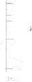
Fig. 1 illustrates a structure schematic diagram of a first viewing angel of an air sweeping mechanism according to the disclosure; -
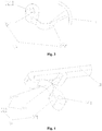
Fig. 2 illustrates a structure schematic diagram of a second viewing angel of the air sweeping mechanism according to the disclosure; -
Fig. 3 illustrates a structure schematic diagram of a first embodiment of a driving portion of the air sweeping mechanism according to the disclosure; -
Fig. 4 illustrates a structure schematic diagram of a second embodiment of the driving portion of the air sweeping mechanism according to the disclosure; -
Fig. 5 illustrates a local structure schematic diagram of air sweeping blade of the air sweeping mechanism according to the disclosure; and -
Fig. 6 illustrates a structure schematic diagram of an air conditioner according to an embodiment of the disclosure. - The drawings include the following reference signs:
10. mounting portion; 20. air sweeping blade; 21. first connecting portion; 22. second connecting portion; 30. driving rod; 31. fixing portion; 32. driving portion; 321. first driving section; 3211. passing hole; 322. second driving section; 3221. first stretching section; 3222. second stretching section; 40. driving motor; and 50. housing. - It is to be noted that the embodiments of the disclosure and the features of the embodiments are combined with each other if there is no conflict. The disclosure is described below in detail with reference to the accompanying drawings and in combination with the embodiments.
- It is to be noted that the following detailed description is illustrative and is intended to provide further illustration for the disclosure. Unless otherwise specified, all technical and scientific terms used in the specification have the same meaning generally understood by the person skilled in the art of the disclosure.
- It is to be noted that terms used herein only aim to describe specific implementation manners, and are not intended to limit exemplar implementations of this disclosure. As used herein, unless otherwise directed by the context, singular forms of terms are intended to include plural forms. Besides, it will be also appreciated that when terms "contain" and/or "include" are used in the description, it is indicated that features, steps, operations, devices, assemblies and/or a combination thereof exist.
- Some embodiments of the disclosure provide an air sweeping mechanism, reference to
Fig. 1 andFig. 2 , the air sweeping mechanism includes amounting portion 10, an air sweepingblade 20 and adriving rod 30, wherein themounting portion 10 is configured to be mounted on ahousing 50 of an air conditioner, the air sweepingblades 20 is connected with themounting portion 10, thedriving rod 30 is connected with theair sweeping blade 20, and a position of thedriving rod 30 is adjustably disposed, wherein theair sweeping blade 20 and thedriving rod 30 are integrally formed, at least part of theair sweeping blade 20 is a flexible portion, and thedriving rod 30 drives the at least part of theair sweeping blade 20 to move. - The air sweeping mechanism of an embodiment of the disclosure is disposed through enabling the
air sweeping blade 20 and thedriving rod 30 to be integrally formed, in a specific assembling process, theair sweeping blade 20 is connected with themounting portion 10, and then themounting portion 10 is installed on thehousing 50 of the air conditioner, so that the installation of the air sweeping mechanism is completed. The air sweeping mechanism of an embodiment of the disclosure is disposed through enabling theair sweeping blade 20 and thedriving rod 30 to be integrally formed, installing steps of theair sweeping blade 20 and thedriving rod 30 are eliminated, and the assembly efficiency of the air sweeping mechanism is improved in a certain degree, thereby a problem in the technology known to inventors that the assembly efficiency of the air sweeping mechanism is lower is solved. - In some embodiments, through enabling at least part of the
air sweeping blade 20 to be set as the flexible portion, and enabling a position of thedriving rod 30 to be adjustably disposed, thereby it is guaranteed that thedriving rod 30 drives at least part of theair sweeping blade 20 to move, so that air sweeping requirements in different orientations of the air sweeping mechanism are guaranteed. - In order to guarantee rapid formation of the
driving rod 30 and theair sweeping blade 20, in an embodiment, thedriving rod 30 and theair sweeping blade 20 are integrally injection-formed. - In order to further improve the assembly efficiency of the air sweeping mechanism, in an embodiment, the
mounting portion 10, theair sweeping blade 20 and thedriving rod 30 are integrally formed. - In some embodiments, the mounting
portion 10, theair sweeping blade 20 and the drivingrod 30 are integrally injection-formed. - In allusion to a specific connecting mode in which the
air sweeping blade 20 is connected with the drivingrod 30, as shown inFig. 2 andFig. 5 , the airsweeping blades 20 includes a first connectingportion 21, the first connectingportion 21 is connected with the drivingrod 30, and the first connectingportion 21 is a flexible portion. - In some embodiments, through installing the first connecting
portion 21 on the airsweeping blades 20, wherein, the first connectingportion 21 is connected with the drivingrod 30, so that theair sweeping blade 20 is connected with the drivingrod 30 through the first connectingportion 21. - In some embodiments, through enabling the first connecting
portion 21 to be set as the flexible portion, thereby it is guaranteed that the first connectingportion 21 does not affect the drivingrod 30 to drive at least part of theair sweeping blade 20 to move. - In some embodiments, the first connecting
portion 21 is a flexible hinge. - In allusion to a specific position of the first connecting
portion 21, a plurality of positions of the first connectingportion 21 as shown inFig. 5 , the first connectingportion 21 is positioned at one end, away from the mountingportion 10, of the airsweeping blades 20; or the first connectingportion 21 is positioned in a middle of theair sweeping blade 20. - In some embodiments, the first connecting
portion 21 is positioned at one end, away from the mountingportion 10, of the airsweeping blades 20, namely, positioned at a top end of theair sweeping blade 20. - In some embodiments, the first connecting
portion 21 is positioned in the middle of the airsweeping blades 20, namely, positioned between the bottom end and the top end of theair sweeping blade 20. - In some embodiments, in order to achieve the connection of the air
sweeping blades 20 and the mountingportion 10, as shown inFig. 2 , each of the airsweeping blades 20 includes a second connectingportion 22, the second connectingportion 22 is connected with the mountingportion 10, at least part, close to the second connectingportion 22, of theair sweeping blade 20 is a flexible portion, so that theair sweeping blade 20 is moveably disposed relative to the mountingportion 10. - In some embodiments, through installing the second connecting
portion 22 on theair sweeping blade 20, wherein, the second connectingportion 22 is connected with the mountingportion 10, so that each of the airsweeping blades 20 is connected with the mountingportion 10 through the second connectingportion 22. - In some embodiment, in order to guarantee that the
air sweeping blade 20 is moved under the driving of the drivingrod 30, at least part, close to the second connectingportion 22, of theair sweeping blade 20 is a flexible portion, thereby under the driving of the drivingrod 30, the flexible portion of theair sweeping blade 20 is deformed, so that theair sweeping blade 20 is moveably disposed relative to the mountingportion 10. - In some embodiments, at least part, close to the second connecting
portion 22, of each of the airsweeping blades 20 is a flexible hinge. - In an embodiment of the present disclosure, as shown in
Fig. 3 and Fig. 4 , the drivingrod 30 includes a fixingportion 31, the fixingportion 31 is connected with the airsweeping blades 20, at least part of the fixingportion 31 is extended along a length direction of the mountingportion 10; and a drivingportion 32, the drivingportion 32 is connected with one end of the fixingportion 31, and a position of the drivingportion 32 is adjustably disposed, so as to drive the fixingportion 31 to move. - In some embodiments, the driving
rod 30 includes the fixingportion 31 and the drivingportion 32, wherein, the fixingportion 31 is connected with the airsweeping blades 20, at least part of the fixingportion 31 is extended along the length direction of the mountingportion 10, and the drivingportion 32 is connected with one end of the fixingportion 31. - In some embodiments, the position of the driving
portion 32 is adjustably disposed, so that theair sweeping blade 20 is driven to be moved by driving the fixingportion 31. - In allusion to a specific structure of the driving
portion 32, as shown inFig. 3 and Fig. 4 , the drivingportion 32 includes afirst driving section 321 and asecond driving section 322, thefirst driving section 321 is provided with a passinghole 3211, the passinghole 3211 is configured to be connected with a rotation shaft of a drivingmotor 40; a first end of thesecond driving section 322 is connected with thefirst driving section 321, and a second end of thesecond driving section 322 is connected with the fixingportion 31, wherein, at least part of thesecond driving section 322 is a flexible portion. - In some embodiments, the driving
portion 32 is formed by thefirst driving section 321 and thesecond driving section 322, wherein, thefirst driving section 321 is provided with the passinghole 3211, the passinghole 3211 is configured to be connected with a rotation shaft of the drivingmotor 40, the first end of thesecond driving section 322 is connected with thefirst driving section 321, and the second end of thesecond driving section 322 is connected with the fixingportion 31. - In some embodiments, through enabling at least part of the
second driving section 322 to be set as the flexible portion, thereby under the driving of the rotation shaft of the drivingmotor 40, at least part of thesecond driving section 322 is bended to be deformed, so as to drive the fixingportion 31 to move. - In the embodiment, the fixing
portion 31 and the drivingportion 32 are integrally formed. - In allusion to a first embodiment of the driving
portion 32, as shown inFig. 3 , thesecond driving section 322 is a flexible hinge. - In allusion to a second embodiment of the driving
portion 32, as shown inFig. 4 , thesecond driving section 322 includes: afirst stretching section 3221 and asecond stretching section 3222, a first end of thefirst stretching section 3221 is connected with thefirst driving section 321, and a second end of thefirst stretching section 3221 is connected with the fixingportion 31; a first end of thesecond stretching section 3222 is connected with thefirst driving section 321, and a second end of thesecond stretching section 3222 is connected with the fixingportion 31, wherein, at least part of thefirst stretching section 3221 is a flexible portion, and at least part of thesecond stretching section 3222 is a flexible portion. - In some embodiments, the
second driving section 322 is formed by thefirst stretching section 3221 and thesecond stretching section 3222, wherein the first end of thefirst stretching section 3221 is connected with thefirst driving section 321, the second end of thefirst stretching section 3221 is connected with the fixingportion 31, the first end of thesecond stretching section 3222 is connected with thefirst driving section 321, and the second end of thesecond stretching section 3222 is connected with the fixingportion 31. - In some embodiments, through enabling at least part of the
first stretching section 3221 to be set as the flexible portion, and enabling at least part of thesecond stretching section 3222 to be set as the flexible portion, under the driving of the rotation shaft of the drivingmotor 40, at least part of thesecond driving section 322 is bended to be deformed, so as to drive the fixingportion 31 to move. - In some embodiments, the second end of the
first stretching section 3221 and the second end of thesecond stretching section 3222 are spaced from each other, and an avoidance cavity is formed between thefirst stretching section 3221, thesecond stretching section 3222, the fixingportion 31 and thefirst driving section 321. - In some embodiments, while the rotation shaft of the driving
motor 40 drives thefirst driving section 321 to be rotated, thefirst stretching section 3221 and thesecond stretching section 3222 are in a full-stretching state, thereby the excessive stress effect is not generated to thefirst stretching section 3221 and thesecond stretching section 3222, so as to guarantee the stable operation of the air sweeping mechanism. - In some embodiments, the air sweeping mechanism further includes: the driving
motor 40. - In some embodiments, the rotation shaft of the driving
motor 40 is clockwise and counterclockwise rotated, wherein, a clockwise angle and a counterclockwise angle are less than or equal to 90 degrees. - Some embodiments of the present disclosure further provides an air conditioner, as shown in
Fig. 6 , the air conditioner includes an air sweeping mechanism, the air sweeping mechanism is the above air sweeping mechanism. - As is seen from the above description, the above embodiments of the disclosure implement the following technical effects.
- The air sweeping mechanism of the disclosure is disposed through enabling the
air sweeping blade 20 and the drivingrod 30 to be integrally formed, in a specific assembling process, theair sweeping blade 20 is connected with the mountingportion 10, and then the mountingportion 10 is installed on ahousing 50 of the air conditioner, so that the installation of the air sweeping mechanism is completed. The air sweeping mechanism of the disclosure is disposed through enabling theair sweeping blade 20 and the drivingrod 30 to be integrally formed, installing steps of theair sweeping blade 20 and the drivingrod 30 are eliminated, and the assembly efficiency of the air sweeping mechanism is improved in a certain degree, thereby the problem in the art known to inventors that the assembly efficiency of the air sweeping mechanism is lower is solved. - It should be noted that, terminologies such as "first" and "second" in the specification, claims and accompanying drawings of the disclosure are only used to distinguish similar objects, rather than to describe a special order or a precedence order. It should be understood that data used in such a way may be interchangeable in a certain case, such that the embodiments of the disclosure described here may be implemented in an order other than those illustrated or described here. In addition, the terms "comprise," "comprising," "include," "including," "has," "having" or any other variation thereof, are intended to cover a non-exclusive inclusion. For example, a process, method, system, product or device that includes a list of steps or units is not necessarily limited only to those steps or units but may include other steps or units not expressly listed or inherent to such process, method, product or device.
- For ease of description, spatial relative terms such as "over", "above", "on an upper surface" and "upper" are used herein for describing a spatial position relation between a device or feature and other devices or features shown in the drawings. It will be appreciated that the spatial relative terms aim to contain different orientations in usage or operation besides the orientations of the devices described in the drawings. For example, if the devices in the drawings are inverted, devices described as "above other devices or structures" or "over other devices or structures" will be located as "below other devices or structures" or "under other devices or structures". Thus, an exemplar term "above" includes two orientations namely "above" and "below". The device may also be located in other different modes (rotated by 90 degrees or located in other orientations), and spatial relative descriptions used herein are correspondingly explained.
- The above are only some embodiments of the disclosure, and are not intended to limit the disclosure. As will occur to those skilled in the art, the disclosure is susceptible to various modifications and changes. Any modification, equivalent replacement, improvement and the like made within a spirit and a principle of the disclosure should be included in a protection scope of the disclosure.
Claims (16)
- An air sweeping mechanism, comprising:a mounting portion (10), the mounting portion (10) being configured to be mounted on a housing (50) of an air conditioner;an air sweeping blade (20), the air sweeping blade (20) being connected with the mounting portion (10); anda driving rod (30), the driving rod (30) being connected with the air sweeping blade (20), and a position of the driving rod (30) being adjustably disposed,wherein the air sweeping blade (20) and the driving rod (30) are integrally formed, at least part of the air sweeping blade (20) is a flexible portion, and the driving rod (30) drives the at least part of the air sweeping blade(20) to move.
- The air sweeping mechanism as claimed in claim 1, wherein the driving rod (30) and the air sweeping blade (20) are integrally injection-formed.
- The air sweeping mechanism as claimed in claim 1, wherein the mounting portion (10), the air sweeping blade (20) and the driving rod (30) are integrally formed.
- The air sweeping mechanism as claimed in claim 3, wherein the mounting portion (10), the air sweeping blade (20) and the driving rod (30) are integrally injection-formed.
- The air sweeping mechanism as claimed in claim 1, wherein the air sweeping blade (20) comprises a first connecting portion (21), the first connecting portion (21) is connected with the driving rod (30), and the first connecting portion (21) is a flexible portion.
- The air sweeping mechanism as claimed in claim 5, wherein the first connecting portion (21) is a flexible hinge.
- The air sweeping mechanism as claimed in claim 5, wherein the first connecting portion (21) is positioned at one end, away from the mounting portion (10), of the air sweeping blade (20); or the first connecting portion (21) is positioned in a middle of the air sweeping blade (20).
- The air sweeping mechanism as claimed in claim 1, wherein the air sweeping blade (20) comprises a second connecting portion (22), the second connecting portion (22) is connected with the mounting portion (10), at least part, close to the second connecting portion (22), of the air sweeping blade (20) is a flexible portion, so that the air sweeping blade (20) is moveably disposed relative to the mounting portion (10).
- The air sweeping mechanism as claimed in claim 8, wherein at least part, close to the second connecting portion (22), of the air sweeping blade (20) is a flexible hinge.
- The air sweeping mechanism as claimed in claim 1, wherein the driving rod (30) comprises:a fixing portion (31), the fixing portion (31) being connected with the air sweeping blade (20), at least part of the fixing portion (31) being extended along a length direction of the mounting portion (10); anda driving portion (32), the driving portion (32) being connected with one end of the fixing portion (31), and a position of the driving portion (32) being adjustably disposed, so as to drive the fixing portion (31) to move.
- The air sweeping mechanism as claimed in claim 10, wherein the driving portion (32) comprises:a first driving section (321), the first driving section (321) being provided with a passing hole (3211), the passing hole (3211) being configured to be connected with a rotation shaft of a driving motor (40); anda second driving section (322), a first end of the second driving section (322) being connected with the first driving section (321), and a second end of the second driving section (322) being connected with the fixing portion (31),wherein at least part of the second driving section (322) is a flexible portion.
- The air sweeping mechanism as claimed in claim 11, wherein the second driving section (322) is a flexible hinge.
- The air sweeping mechanism as claimed in claim 11, wherein the second driving section (322) comprises:a first stretching section (3221), a first end of the first stretching section (3221) being connected with the first driving section (321), and a second end of the first stretching section (3221) being connected with the fixing portion (31); anda second stretching section (3222), a first end of the second stretching section (3222) being connected with the first driving section (321), and a second end of the second stretching section (3222) being connected with the fixing portion (31),wherein at least part of the first stretching section (3221) is a flexible portion, and at least part of the second stretching section (3222) is a flexible portion.
- The air sweeping mechanism as claimed in claim 13, wherein the second end of the first stretching section (3221) and the second end of the second stretching section (3222) are spaced from each other, and an avoidance cavity is formed between the first stretching section (3221), the second stretching section (3222), the fixing portion (31) and the first driving section (321).
- The air sweeping mechanism as claimed in claim 11, wherein the rotation shaft of the driving motor (40) is clockwise and counterclockwise rotated, wherein, a clockwise angle and a counterclockwise angle are less than or equal to 90 degrees.
- An air conditioner, comprising an air sweeping mechanism, wherein the air sweeping mechanism is the air sweeping mechanism as claimed in claim 1.
Applications Claiming Priority (2)
| Application Number | Priority Date | Filing Date | Title |
|---|---|---|---|
| CN201810015384.2A CN108131813B (en) | 2018-01-08 | 2018-01-08 | Air sweeping mechanism and air conditioner with same |
| PCT/CN2018/118960 WO2019134472A1 (en) | 2018-01-08 | 2018-12-03 | Air sweeping mechanism and air conditioner having same |
Publications (2)
| Publication Number | Publication Date |
|---|---|
| EP3739275A1 true EP3739275A1 (en) | 2020-11-18 |
| EP3739275A4 EP3739275A4 (en) | 2021-10-06 |
Family
ID=62399537
Family Applications (1)
| Application Number | Title | Priority Date | Filing Date |
|---|---|---|---|
| EP18898368.8A Pending EP3739275A4 (en) | 2018-01-08 | 2018-12-03 | Air sweeping mechanism and air conditioner having same |
Country Status (4)
| Country | Link |
|---|---|
| US (1) | US11821648B2 (en) |
| EP (1) | EP3739275A4 (en) |
| CN (1) | CN108131813B (en) |
| WO (1) | WO2019134472A1 (en) |
Families Citing this family (4)
| Publication number | Priority date | Publication date | Assignee | Title |
|---|---|---|---|---|
| CN108131813B (en) | 2018-01-08 | 2023-11-14 | 珠海格力电器股份有限公司 | Air sweeping mechanism and air conditioner with same |
| CN109373559A (en) * | 2018-11-26 | 2019-02-22 | 珠海格力电器股份有限公司 | Sweep wind mechanism and air conditioner |
| CN111780389B (en) * | 2020-06-16 | 2022-06-10 | 重庆海尔空调器有限公司 | Air supply mechanism and air conditioner with same |
| JP7579165B2 (en) | 2021-02-04 | 2024-11-07 | シャープ株式会社 | Air conditioners |
Family Cites Families (20)
| Publication number | Priority date | Publication date | Assignee | Title |
|---|---|---|---|---|
| JP3463430B2 (en) * | 1995-10-20 | 2003-11-05 | 株式会社富士通ゼネラル | Air conditioner |
| JPH10141754A (en) * | 1996-11-15 | 1998-05-29 | Matsushita Electric Ind Co Ltd | Air conditioners and air direction change devices for air conditioners |
| US6207092B1 (en) * | 1999-05-28 | 2001-03-27 | K. Jabat, Inc. | Process for making a drag shield for a power mower |
| US20020175305A1 (en) * | 2001-05-25 | 2002-11-28 | Mccabe Francis J. | Multiblade damper with DC actuator and double knee lock blade operator |
| CN201680560U (en) * | 2010-04-09 | 2010-12-22 | 珠海格力电器股份有限公司 | Wall-mounted air conditioner |
| CN202267188U (en) * | 2011-08-17 | 2012-06-06 | 格力电器(武汉)有限公司 | Wind sweeping structure for wall hanging type air conditioner |
| CN202254170U (en) * | 2011-10-13 | 2012-05-30 | 珠海格力电器股份有限公司 | Air conditioner wind sweeping blade structure |
| CN103542508B (en) * | 2012-07-13 | 2016-08-03 | 珠海格力电器股份有限公司 | Wind sweeping structure and air conditioner with same |
| CN104101070A (en) * | 2013-04-02 | 2014-10-15 | 珠海格力电器股份有限公司 | Air deflector and air conditioner with same |
| CN203375644U (en) * | 2013-06-07 | 2014-01-01 | 广东美的制冷设备有限公司 | Air conditioner air guiding mechanism and air conditioner |
| CN203454360U (en) * | 2013-07-29 | 2014-02-26 | 广东美的制冷设备有限公司 | Air-conditioner and air guide device thereof |
| CN203980590U (en) * | 2014-05-30 | 2014-12-03 | 广东美的制冷设备有限公司 | Blinds mounting structure and air-conditioner |
| CN104121682B (en) * | 2014-08-13 | 2017-05-17 | 珠海格力电器股份有限公司 | Air conditioner and wind sweeping mechanism thereof |
| CN104236043B (en) * | 2014-08-27 | 2017-02-15 | 珠海格力电器股份有限公司 | Wind sweeping blade, wind sweeping mechanism and air conditioner |
| CN204718056U (en) * | 2015-05-28 | 2015-10-21 | 宁波奥克斯空调有限公司 | Sweep the syndeton of air blade and connecting rod |
| CN105371466B (en) * | 2015-12-07 | 2019-06-07 | 珠海格力电器股份有限公司 | Air guide mechanism and air conditioner indoor unit |
| CN106642619A (en) * | 2016-11-26 | 2017-05-10 | 珠海格力电器股份有限公司 | Wind sweeping blade assembly, air conditioning device and control method of wind sweeping blade assembly |
| CN107525250B (en) * | 2017-08-02 | 2020-03-03 | 广东美的暖通设备有限公司 | Air outlet panel assembly and central air conditioner indoor unit having the same |
| CN207815662U (en) * | 2018-01-08 | 2018-09-04 | 珠海格力电器股份有限公司 | Sweep wind mechanism and have its air conditioner |
| CN108131813B (en) * | 2018-01-08 | 2023-11-14 | 珠海格力电器股份有限公司 | Air sweeping mechanism and air conditioner with same |
-
2018
- 2018-01-08 CN CN201810015384.2A patent/CN108131813B/en active Active
- 2018-12-03 US US16/960,768 patent/US11821648B2/en active Active
- 2018-12-03 EP EP18898368.8A patent/EP3739275A4/en active Pending
- 2018-12-03 WO PCT/CN2018/118960 patent/WO2019134472A1/en not_active Ceased
Also Published As
| Publication number | Publication date |
|---|---|
| US11821648B2 (en) | 2023-11-21 |
| EP3739275A4 (en) | 2021-10-06 |
| WO2019134472A1 (en) | 2019-07-11 |
| CN108131813B (en) | 2023-11-14 |
| CN108131813A (en) | 2018-06-08 |
| US20200400342A1 (en) | 2020-12-24 |
Similar Documents
| Publication | Publication Date | Title |
|---|---|---|
| US11821648B2 (en) | Air sweeping mechanism and air conditioner with air sweeping mechanism | |
| US11680716B2 (en) | Window air conditioner sealing device | |
| EP3282131B1 (en) | Ceiling fan blade structure and ceiling fan comprising the same | |
| CN107606765A (en) | Air conditioner panel assembly | |
| EP3683509B1 (en) | Air guide mechanism and air conditioner provided with same | |
| CN106524301B (en) | Air conditioner indoor unit, air conditioner and control method | |
| CN103542508A (en) | Wind sweeping structure and air conditioner with same | |
| CN106247585A (en) | A kind of indoor apparatus of air conditioner air deflection assemblies and indoor apparatus of air conditioner | |
| WO2020134235A1 (en) | Unmanned aerial vehicle and wing assembly thereof | |
| CN105810112A (en) | Front maintenance structure of small-spacing LED display screen | |
| CN108962036B (en) | A foldable display device | |
| CN106288285A (en) | Air conditioner, sweep wind subassembly and sweep wind blade thereof | |
| CN112484147B (en) | Air conditioner | |
| CN206125442U (en) | Unmanned aerial vehicle motor mount pad and unmanned aerial vehicle | |
| CN207555933U (en) | Wind guiding component, housing unit and the window air conditioner of window air conditioner | |
| CN205630680U (en) | Arm and robot | |
| CN110319561B (en) | Air outlet frame structure and air conditioner indoor unit with same | |
| CN210891901U (en) | Air conditioner indoor unit | |
| CN105526698A (en) | Bottom shell assembly and air conditioner with same | |
| CN106766064B (en) | Panel components and air-conditioning cabinets | |
| CN211551810U (en) | Motor element, air conditioner and air conditioner | |
| CN105592652B (en) | Case for communication equipment | |
| CN108870708B (en) | Air guide structure, panel body structure and air conditioner | |
| CN109017211B (en) | Derailment-preventing air conditioner air door | |
| CN204438464U (en) | Air guide structure and air-conditioner |
Legal Events
| Date | Code | Title | Description |
|---|---|---|---|
| STAA | Information on the status of an ep patent application or granted ep patent |
Free format text: STATUS: THE INTERNATIONAL PUBLICATION HAS BEEN MADE |
|
| PUAI | Public reference made under article 153(3) epc to a published international application that has entered the european phase |
Free format text: ORIGINAL CODE: 0009012 |
|
| STAA | Information on the status of an ep patent application or granted ep patent |
Free format text: STATUS: REQUEST FOR EXAMINATION WAS MADE |
|
| 17P | Request for examination filed |
Effective date: 20200630 |
|
| AK | Designated contracting states |
Kind code of ref document: A1 Designated state(s): AL AT BE BG CH CY CZ DE DK EE ES FI FR GB GR HR HU IE IS IT LI LT LU LV MC MK MT NL NO PL PT RO RS SE SI SK SM TR |
|
| AX | Request for extension of the european patent |
Extension state: BA ME |
|
| DAV | Request for validation of the european patent (deleted) | ||
| DAX | Request for extension of the european patent (deleted) | ||
| A4 | Supplementary search report drawn up and despatched |
Effective date: 20210906 |
|
| RIC1 | Information provided on ipc code assigned before grant |
Ipc: F24F 1/0011 20190101ALI20210831BHEP Ipc: F24F 13/15 20060101ALI20210831BHEP Ipc: F24F 13/14 20060101AFI20210831BHEP |
|
| P01 | Opt-out of the competence of the unified patent court (upc) registered |
Effective date: 20230530 |
|
| STAA | Information on the status of an ep patent application or granted ep patent |
Free format text: STATUS: EXAMINATION IS IN PROGRESS |
|
| 17Q | First examination report despatched |
Effective date: 20230731 |