EP3739206A1 - Bearing arrangement for a wind turbine and wind turbine - Google Patents
Bearing arrangement for a wind turbine and wind turbine Download PDFInfo
- Publication number
- EP3739206A1 EP3739206A1 EP19174862.3A EP19174862A EP3739206A1 EP 3739206 A1 EP3739206 A1 EP 3739206A1 EP 19174862 A EP19174862 A EP 19174862A EP 3739206 A1 EP3739206 A1 EP 3739206A1
- Authority
- EP
- European Patent Office
- Prior art keywords
- bearing
- axial
- drive shaft
- arrangement
- stop
- Prior art date
- Legal status (The legal status is an assumption and is not a legal conclusion. Google has not performed a legal analysis and makes no representation as to the accuracy of the status listed.)
- Granted
Links
- 239000012530 fluid Substances 0.000 claims abstract description 4
- 239000000314 lubricant Substances 0.000 description 26
- 238000007789 sealing Methods 0.000 description 20
- 238000004519 manufacturing process Methods 0.000 description 9
- 239000000428 dust Substances 0.000 description 7
- 238000012423 maintenance Methods 0.000 description 5
- 230000001174 ascending effect Effects 0.000 description 2
- 238000010420 art technique Methods 0.000 description 1
- 229920001971 elastomer Polymers 0.000 description 1
- 239000000806 elastomer Substances 0.000 description 1
- 230000010354 integration Effects 0.000 description 1
Images


Classifications
-
- F—MECHANICAL ENGINEERING; LIGHTING; HEATING; WEAPONS; BLASTING
- F03—MACHINES OR ENGINES FOR LIQUIDS; WIND, SPRING, OR WEIGHT MOTORS; PRODUCING MECHANICAL POWER OR A REACTIVE PROPULSIVE THRUST, NOT OTHERWISE PROVIDED FOR
- F03D—WIND MOTORS
- F03D80/00—Details, components or accessories not provided for in groups F03D1/00 - F03D17/00
- F03D80/70—Bearing or lubricating arrangements
-
- F—MECHANICAL ENGINEERING; LIGHTING; HEATING; WEAPONS; BLASTING
- F16—ENGINEERING ELEMENTS AND UNITS; GENERAL MEASURES FOR PRODUCING AND MAINTAINING EFFECTIVE FUNCTIONING OF MACHINES OR INSTALLATIONS; THERMAL INSULATION IN GENERAL
- F16C—SHAFTS; FLEXIBLE SHAFTS; ELEMENTS OR CRANKSHAFT MECHANISMS; ROTARY BODIES OTHER THAN GEARING ELEMENTS; BEARINGS
- F16C17/00—Sliding-contact bearings for exclusively rotary movement
- F16C17/04—Sliding-contact bearings for exclusively rotary movement for axial load only
- F16C17/06—Sliding-contact bearings for exclusively rotary movement for axial load only with tiltably-supported segments, e.g. Michell bearings
-
- F—MECHANICAL ENGINEERING; LIGHTING; HEATING; WEAPONS; BLASTING
- F16—ENGINEERING ELEMENTS AND UNITS; GENERAL MEASURES FOR PRODUCING AND MAINTAINING EFFECTIVE FUNCTIONING OF MACHINES OR INSTALLATIONS; THERMAL INSULATION IN GENERAL
- F16C—SHAFTS; FLEXIBLE SHAFTS; ELEMENTS OR CRANKSHAFT MECHANISMS; ROTARY BODIES OTHER THAN GEARING ELEMENTS; BEARINGS
- F16C17/00—Sliding-contact bearings for exclusively rotary movement
- F16C17/10—Sliding-contact bearings for exclusively rotary movement for both radial and axial load
-
- F—MECHANICAL ENGINEERING; LIGHTING; HEATING; WEAPONS; BLASTING
- F16—ENGINEERING ELEMENTS AND UNITS; GENERAL MEASURES FOR PRODUCING AND MAINTAINING EFFECTIVE FUNCTIONING OF MACHINES OR INSTALLATIONS; THERMAL INSULATION IN GENERAL
- F16C—SHAFTS; FLEXIBLE SHAFTS; ELEMENTS OR CRANKSHAFT MECHANISMS; ROTARY BODIES OTHER THAN GEARING ELEMENTS; BEARINGS
- F16C33/00—Parts of bearings; Special methods for making bearings or parts thereof
- F16C33/02—Parts of sliding-contact bearings
- F16C33/04—Brasses; Bushes; Linings
- F16C33/06—Sliding surface mainly made of metal
- F16C33/10—Construction relative to lubrication
- F16C33/1025—Construction relative to lubrication with liquid, e.g. oil, as lubricant
- F16C33/106—Details of distribution or circulation inside the bearings, e.g. details of the bearing surfaces to affect flow or pressure of the liquid
- F16C33/108—Details of distribution or circulation inside the bearings, e.g. details of the bearing surfaces to affect flow or pressure of the liquid with a plurality of elements forming the bearing surfaces, e.g. bearing pads
-
- F—MECHANICAL ENGINEERING; LIGHTING; HEATING; WEAPONS; BLASTING
- F05—INDEXING SCHEMES RELATING TO ENGINES OR PUMPS IN VARIOUS SUBCLASSES OF CLASSES F01-F04
- F05B—INDEXING SCHEME RELATING TO WIND, SPRING, WEIGHT, INERTIA OR LIKE MOTORS, TO MACHINES OR ENGINES FOR LIQUIDS COVERED BY SUBCLASSES F03B, F03D AND F03G
- F05B2240/00—Components
- F05B2240/50—Bearings
-
- F—MECHANICAL ENGINEERING; LIGHTING; HEATING; WEAPONS; BLASTING
- F16—ENGINEERING ELEMENTS AND UNITS; GENERAL MEASURES FOR PRODUCING AND MAINTAINING EFFECTIVE FUNCTIONING OF MACHINES OR INSTALLATIONS; THERMAL INSULATION IN GENERAL
- F16C—SHAFTS; FLEXIBLE SHAFTS; ELEMENTS OR CRANKSHAFT MECHANISMS; ROTARY BODIES OTHER THAN GEARING ELEMENTS; BEARINGS
- F16C17/00—Sliding-contact bearings for exclusively rotary movement
- F16C17/02—Sliding-contact bearings for exclusively rotary movement for radial load only
- F16C17/03—Sliding-contact bearings for exclusively rotary movement for radial load only with tiltably-supported segments, e.g. Michell bearings
-
- F—MECHANICAL ENGINEERING; LIGHTING; HEATING; WEAPONS; BLASTING
- F16—ENGINEERING ELEMENTS AND UNITS; GENERAL MEASURES FOR PRODUCING AND MAINTAINING EFFECTIVE FUNCTIONING OF MACHINES OR INSTALLATIONS; THERMAL INSULATION IN GENERAL
- F16C—SHAFTS; FLEXIBLE SHAFTS; ELEMENTS OR CRANKSHAFT MECHANISMS; ROTARY BODIES OTHER THAN GEARING ELEMENTS; BEARINGS
- F16C2300/00—Application independent of particular apparatuses
- F16C2300/10—Application independent of particular apparatuses related to size
- F16C2300/14—Large applications, e.g. bearings having an inner diameter exceeding 500 mm
-
- F—MECHANICAL ENGINEERING; LIGHTING; HEATING; WEAPONS; BLASTING
- F16—ENGINEERING ELEMENTS AND UNITS; GENERAL MEASURES FOR PRODUCING AND MAINTAINING EFFECTIVE FUNCTIONING OF MACHINES OR INSTALLATIONS; THERMAL INSULATION IN GENERAL
- F16C—SHAFTS; FLEXIBLE SHAFTS; ELEMENTS OR CRANKSHAFT MECHANISMS; ROTARY BODIES OTHER THAN GEARING ELEMENTS; BEARINGS
- F16C2360/00—Engines or pumps
- F16C2360/31—Wind motors
-
- Y—GENERAL TAGGING OF NEW TECHNOLOGICAL DEVELOPMENTS; GENERAL TAGGING OF CROSS-SECTIONAL TECHNOLOGIES SPANNING OVER SEVERAL SECTIONS OF THE IPC; TECHNICAL SUBJECTS COVERED BY FORMER USPC CROSS-REFERENCE ART COLLECTIONS [XRACs] AND DIGESTS
- Y02—TECHNOLOGIES OR APPLICATIONS FOR MITIGATION OR ADAPTATION AGAINST CLIMATE CHANGE
- Y02E—REDUCTION OF GREENHOUSE GAS [GHG] EMISSIONS, RELATED TO ENERGY GENERATION, TRANSMISSION OR DISTRIBUTION
- Y02E10/00—Energy generation through renewable energy sources
- Y02E10/70—Wind energy
- Y02E10/72—Wind turbines with rotation axis in wind direction
Definitions
- the invention relates to a bearing arrangement for a wind turbine and a wind turbine.
- bearing arrangements of wind turbines comprise a bearing housing and a drive shaft, whereby the drive shaft is arranged within the bearing housing in an axial direction along a longitudinal axis of the bearing housing.
- Bearings of the bearing arrangement are arranged about the drive shaft, so that the drive shaft can be rotated within the bearing housing by means of a rotor of the wind turbine.
- Such a bearing arrangement is known from EP 3 276 192 A1 , for example.
- the bearing arrangement must be provided with axial load taking capabilities to be able to take an axial load from an axial or thrust force of the drive shaft.
- axial load taking capabilities may be provided by an axial bearing, which may be structurally integrated with the bearing arrangement.
- current solutions e.g. a bolt connection between the axial collar of an axial bearing and the drive shaft, have a leakage potential, are cumbersome in their manufacture and difficult to service.
- the invention relates to a bearing arrangement for a wind turbine comprising a bearing housing and a drive shaft, whereby the drive shaft is arranged within the bearing housing in an axial direction along a longitudinal axis of the bearing housing, the bearing arrangement further comprising a downwind bearing and an upwind bearing as radial fluid bearings, whereby the downwind bearing and the upwind bearing are arranged between the bearing housing and the drive shaft, the bearing arrangement further comprising an axial bearing, whereby the axial bearing comprises an axial bearing stop for limiting a movement of the drive shaft in an axial direction along the longitudinal axis, whereby the axial bearing stop is integrally formed with the bearing housing as a protrusion extending from the bearing housing in a radial direction of the bearing housing.
- the bearing arrangement of the invention is simple to manufacture in that it requires few manufacturing steps.
- the axial bearing stop is monolithically designed with the drive shaft.
- a particularly simple manufacturing method of the axial bearing stop is provided and structural integrity of the axial bearing stop and the bearing housing is further improved.
- multiple axial bearing pads are, in particular reversibly, attached to the axial bearing stop.
- an effective path of the axial bearing can be formed between the multiple axial bearing pads and a counter-part of the multiple axial bearing pads.
- the axial bearing pads may comprise an elastomer for contacting the counter-part of the axial bearing pads of the axial bearing, for example.
- the axial bearing pads may be serviced or replaced when they are worn off or fail due to the load applied onto them during axial loading.
- the multiple axial bearing pads are attached to the axial bearing stop by means of multiple attachment openings arranged in the axial bearing stop. Inserted into the multiple attachment openings may be axial bearing bodies and/or axial tiltable support structures, to which the axial bearing pads are attached.
- the axial bearing bodies, axial tiltable support structures or axial bearing pads may be secured to the axial bearing stop by connection means, such as bolts, for example.
- Axial bearing pads attached via axial tiltable support structures to the axial bearing stop allow for the axial bearing pads to be tiltable with respect to a counter-part of the axial bearing pads such as an axial collar. Thereby, tolerances between counter-part and the axial bearing pads can be compensated for.
- the axial bearing stop is arranged about an entire circumference of the bearing housing.
- a large mass on the axial bearing stop for taking axial loads is provided and the overall load distribution on the axial bearing stop is improved.
- the axial bearing stop is arranged inwards of the bearing housing.
- the axial bearing stop extends radially inwards towards the drive shaft.
- the axial bearing stop extends radially inwards relative to a cylindrical surface of the bearing housing.
- the axial bearing is arranged at a downwind portion or an upwind portion of the drive shaft.
- the downwind portion may be a portion extending from a downwind end of the drive shaft in an axial direction along the longitudinal axis to an upwind end of the drive shaft and having a length of 10% of an entire length of the drive shaft.
- the upwind portion may be a portion extending from an upwind end of the drive shaft in an axial direction along the longitudinal axis to a downwind end of the drive shaft and having a length of 10% of an entire length of the drive shaft.
- the axial bearing may be arranged at the downwind end or the upwind end of the drive shaft.
- the axial bearing stop is arranged at a downwind end of the bearing housing.
- the axial bearing stop may take the axial loads along the entire bearing housing.
- the downwind bearing or the upwind bearing of the bearing arrangement is located adjacent to the axial bearing. Thereby, the manufacturing of the bearings may be further facilitated.
- the downwind bearing or the upwind bearing is fluidically connected to the axial bearing.
- a lubricant e.g. oil
- a radial bearing and an axial bearing can be combined so as to reduce the maintenance requirements with regard to providing the lubricant in the bearings.
- the downwind bearing or the upwind bearing is fluidically connected to the axial bearing.
- a lubricant e.g. oil
- a radial bearing and an axial bearing can be combined so as to reduce the maintenance requirements with regard to providing the lubricant in the bearings.
- the axial bearing comprises an axial collar arranged opposite of the axial bearing stop.
- the axial collar is a reliable counter-part for the axial bearing stop in the axial bearing, when the drive shaft is axially moved in an axial direction along the longitudinal axis.
- the axial collar is arranged at the drive shaft.
- the design of the axial bearing can be kept compact and without any additional parts.
- the axial collar is arranged about an entire circumference of the drive shaft and/or the axial collar extends outwards of the drive shaft.
- a large surface on the axial collar for taking axial loads is provided and the overall load distribution on the axial collar is improved.
- That the axial collar extends outwards of the drive shaft means in other words that the axial collar extends radially outwards relative to a cylindrical surface of the drive shaft.
- the axial collar is favorably located on an outside of the drive shaft, which allows for a simple design of the axial bearing.
- the axial collar is integrally formed with the drive shaft.
- the drive shaft there are no weak points between the axial collar and the drive shaft, such as bolt connections, which would have a potential of leaking lubricant from the axial bearing or which would require maintenance.
- the manufacture of such an integral design requires few manufacturing steps.
- the axial collar may be monolithically designed with the drive shaft.
- a particularly simple manufacturing method of the axial collar is provided and structural integrity is further improved.
- the invention relates to a wind turbine comprising a bearing arrangement according to the invention, whereby the wind turbine further comprises a rotor connected to drive the drive shaft and a generator connected to be driven by the drive shaft.
- the generator may be a direct drive generator or a geared generator having a gearbox, for example.
- the rotor is also commonly referred to as a hub of the wind turbine. Two, three or more wind turbine blades may be attached to the rotor or hub.
- the wind turbine may further comprise a nacelle, which may be supported on a tower of the wind turbine.
- the nacelle may comprise the bearing arrangement. The bearing arrangement, in particular the bearing housing, and the generator may be attached to the nacelle and/or the tower.
- FIG. 1 to 7 Same objects in FIG. 1 to 7 are denominated with the same reference number. If there is more than one object of the same kind in one of the figures, the objects are numbered in ascending order with the ascending number of the object being separated from its reference number by a dot.
- the specific dimensions of features and parts in the figures are exemplary and may be enlarged for ease of reference only.
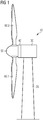
- FIG. 1 shows a side view on a wind turbine 10.
- the wind turbine 10 comprises a supporting tower 20 and a nacelle 30, whereby the nacelle 30 is attached to the supporting tower 20.
- the nacelle 30 comprises a bearing arrangement 70, which is not shown in FIG. 1 but can be seen in FIG. 2 .
- the wind turbine 10 further comprises a generator 40 attached to a rotor 50 of the wind turbine 10. Two wind turbine blades 60.1, 60.2 are attached to the rotor 50.
- FIG. 2 shows a side perspective view on a sectional cut along the longitudinal axis A of the bearing arrangement 70 of the wind turbine 10 of FIG. 1 .
- the bearing arrangement 70 comprises a bearing housing 80 and a drive shaft 90, whereby the drive shaft 90 is arranged within the bearing housing 80 in an axial direction along the longitudinal axis A of the bearing housing 80 as indicated in FIG. 2 .
- the longitudinal axis A of the bearing housing 80 corresponds to the longitudinal axis A of the drive shaft 90 and thereby is a longitudinal axis A of the bearing arrangement 70.
- the bearing arrangement 90 further comprises a downwind bearing 100 and an upwind bearing 200 as radial fluid bearings, whereby the downwind bearing 100 and the upwind bearing 200 are arranged between the bearing housing 80 and the drive shaft 90.
- the downwind bearing 100 is arranged about a downwind portion of the drive shaft 90 and the upwind bearing 200 is arranged about an upwind portion of the drive shaft 90.
- the drive shaft 90 is operatively connected to the generator 40.
- the generator 40 is shown as a direct drive generator. However, it is also possible to provide the generator 40 as a geared generator, for example.
- FIG. 3 shows a side view on a sectional cut along the longitudinal axis A of the bearing arrangement 70 of FIG. 2 .
- An internal space 82 of the bearing housing 80 is formed between the bearing housing 80 and the drive shaft 90.
- Lubricant may leak from the downwind bearing 100 and the upwind bearing 200 into the internal space 82 and thereby be collected in the bearing housing 80, which is formed as a funnel 85 in a bottom part of the bearing housing 80.
- a lubricant pump 88 is fluidically connected to a drain outlet (not shown) of the bearing housing 80.
- the downwind bearing 100 comprising a lubricant flooded chamber 101
- the upwind bearing 200 comprising a lubricant flooded chamber 201 are shown, the principle and features of which will further be explained with reference to FIG. 4 and FIG. 5 .
- FIG. 4 shows an enlarged view on the sectional cut through the upwind bearing 200 and its lubricant flooded chamber 201 according to the detail IV of FIG. 3 .
- a radial bearing body 203 is attached to the bearing housing 80. Specifically, the radial bearing body 203 is attached to a cylindrical seat 202 formed in the bearing housing 80.
- a radial tiltable support structure 204 is secured to the radial bearing body 203.
- a radial bearing pad 205 is attached to the radial tiltable support structure 204.
- the radial bearing pad 205 is arranged in sliding contact with the drive shaft 90.
- the radial tiltable support structure 204 allows for a tilting movement of the radial bearing pad 205.
- radial bearing units comprising a radial bearing body 203, a radial tiltable support structure 204 and a radial bearing pad 205 are arranged in series along the cylindrical seat 202 in the lubricant flooded chamber 201, in particular along a circumference of the cylindrical seat 202 of the upwind bearing 200.
- the lubricant flooded chamber 201 of the upwind bearing 200 is sealed by means of an inner sealing 206 against the internal space 82 of the bearing housing 80.
- the inner sealing 206 of the lubricant flooded chamber 201 of the upwind bearing 200 comprises multiple inner sealing plates 207.
- Two lip seals 212.1, 212.2 are arranged in series between the inner sealing 206 and the drive shaft 90 so as to seal the sealing 206 against the drive shaft 90.
- the lubricant flooded chamber 201 of the upwind bearing 200 is sealed against an outside of the bearing housing 80 by means of an outer sealing 208 and a dust sealing 210.
- the outer sealing 208 comprises an outer seal plate 209 and two lip seals 212.3, 212.4 arranged in series in between the outer seal plate 209 and the drive shaft 90.
- the dust sealing 210 is formed by a dust seal plate 211 and a further lip seal 212.5 arranged between the dust seal plate and the drive shaft 90.
- the dust sealing 210 is located towards the outside of the bearing housing 80.
- the dust sealing 210 sandwiches the outer sealing 208 in between the dust sealing 210 and the outer sealing 206.
- FIG. 5 shows an enlarged view on the sectional cut through the downwind bearing 100 and its lubricant flooded chamber 101 according to the detail V of FIG. 3 .
- a radial bearing body 103 is attached to a bearing housing 80. Specifically, the radial bearing body 103 is attached to a cylindrical seat 102 formed in the bearing housing 80.
- a radial tiltable support structure 104 is secured to the radial bearing body 103.
- a radial bearing pad 105 is attached to the radial tiltable support structure 104.
- the radial bearing pad 105 is arranged in sliding contact with the drive shaft 90.
- the radial tiltable support structure 104 allows for a tilting movement of the radial bearing pad 105.
- radial bearing units comprising a radial bearing body 103, a radial tiltable support structure 104 and a radial bearing pad 105 are arranged in a series along the cylindrical seat 102 in the lubricant flooded chamber 101, in particular along a circumference of the cylindrical seat 102 of the downwind bearing 100.
- the lubricant flooded chamber 101 of the downwind bearing 100 is sealed by means of an inner sealing 106 against the internal space 82 of the bearing housing 80.
- the inner sealing 106 of the lubricant flooded chamber 101 of the downwind bearing 100 comprises multiple inner sealing plates 107.
- Two lip seals 112.1, 112.2 are arranged in series between the inner sealing 106 and the drive shaft 90 so as to seal the sealing 106 against the drive shaft 90.
- the lubricant flooded chamber 101 is fluidically connected to an effective path provided by a lubricant flow channel 303 of an axial bearing 300 of the bearing arrangement 70.
- the axial bearing 300 comprises an axial collar 301 and multiple axial bearing pads (not shown here, because the sectional cut goes through the axial bearing stop 302, only) attached to an axial bearing stop 302.
- the axial collar 301 extends outwards from the drive shaft 90.
- the axial collar 301 extends along an entire circumference of the drive shaft 90.
- the lubricant flow channel 303 of the axial bearing 300 is formed between the axial collar 301 and the multiple axial bearing pads of the axial bearing stop 302.
- An overflow channel 304 of the axial bearing 300 is arranged in fluidical contact with the lubricant flooded chamber 101. By means of the overflow channel 304, excessive lubricant may be released out of the lubricant flooded chamber 101.
- the overflow channel 304 may be connected to the internal space 82 for releasing the lubricant into the bearing housing 80.
- the downwind bearing 100 has the axial bearing 300 as a sealing of the oil flooded chamber 101 against the outside of the bearing housing 80.
- FIG. 6 shows a side perspective view on another bearing arrangement 70 of the wind turbine 10 of FIG. 1 , in which the downwind bearing 100 and the upwind bearing 200 have been omitted for presentation purposes only.
- the drive shaft 90 has a cylindrical shape.
- the bearing housing 80 has a cylindrical shape.
- FIG. 7 shows a view on a detail VII of the bearing arrangement 70 of FIG. 6 .
- the axial collar 301 of the axial bearing is integrally formed with the drive shaft 90.
- the axial collar 301 extends radially outwards from the drive shaft 90 and along an entire circumference of the drive shaft 90, whereby due to the sectional cut this can only have been seen partially.
- the axial bearing stop 302 is integrally formed with the bearing housing 80.
- the axial bearing stop 302 extends as a protrusion of the bearing housing 80 inwards towards the drive shaft 90.
- the axial bearing stop 302 is at a right angle or an approximate right angle with the bearing housing 80.
- the axial bearing stop 302 comprises multiple axial bearing attachment openings 305.1, 305.2 along its circumference for attaching axial bearing pads thereto.
- the multiple axial bearing attachment openings 305.1, 305.2 may be designed so as to have axial bearing bodies and/or axial tiltable support structures, to which the axial bearing pads are attached, inserted therein.
- the axial bearing attachment openings 305.1, 305.2 have a rectangular shape.
- the axial bearing bodies and/or the axial tiltable support structures may be secured to the axial bearing stop 302 by means of press-fitting into the axial bearing attachment openings 305.1, 305.2 and/or by means of axial bearing connection means 306.
- the axial bearing connection means 306 may be threaded holes of the axial bearing stop 302, as shown in FIG. 7 .
- Multiple axial bearing connection means 306 may be arranged around the axial bearing attachment openings 305.1, 305.2, as shown in FIG. 7 in a rectangular shaped manner.
- Bolts may be inserted into the axial bearing connection means 306 and the axial bearing bodies and/or the axial tiltable support structures to secure the axial bearing pads thereto.
Abstract
Description
- The invention relates to a bearing arrangement for a wind turbine and a wind turbine.
- In general, bearing arrangements of wind turbines comprise a bearing housing and a drive shaft, whereby the drive shaft is arranged within the bearing housing in an axial direction along a longitudinal axis of the bearing housing. Bearings of the bearing arrangement are arranged about the drive shaft, so that the drive shaft can be rotated within the bearing housing by means of a rotor of the wind turbine. Such a bearing arrangement is known from
EP 3 276 192 A1 , for example. - The bearing arrangement must be provided with axial load taking capabilities to be able to take an axial load from an axial or thrust force of the drive shaft. Such axial load taking capabilities may be provided by an axial bearing, which may be structurally integrated with the bearing arrangement. However, current solutions, e.g. a bolt connection between the axial collar of an axial bearing and the drive shaft, have a leakage potential, are cumbersome in their manufacture and difficult to service.
- It is an object of the invention to eliminate or at least reduce disadvantages in the prior art techniques related to the structural integration of an axial bearing in the bearing arrangement, in particular to provide a bearing arrangement for a wind turbine with an axial bearing having no or little leakage potential, which is simple to manufacture and requires no or little maintenance.
- This object is solved by the subject-matter of the claims. In particular, the object is solved by a bearing arrangement of a wind turbine according to claim 1 and a wind turbine according to claim 15. Further details of the invention unfold from the other claims as well as the description and the drawings. Thereby, the features and details described in connection with the bearing arrangement of the invention apply in connection with the wind turbine of the invention, so that regarding the disclosure of the individual aspects of the invention it is or can be referred to one another.
- According to a first aspect of the invention, the invention relates to a bearing arrangement for a wind turbine comprising a bearing housing and a drive shaft, whereby the drive shaft is arranged within the bearing housing in an axial direction along a longitudinal axis of the bearing housing, the bearing arrangement further comprising a downwind bearing and an upwind bearing as radial fluid bearings, whereby the downwind bearing and the upwind bearing are arranged between the bearing housing and the drive shaft, the bearing arrangement further comprising an axial bearing, whereby the axial bearing comprises an axial bearing stop for limiting a movement of the drive shaft in an axial direction along the longitudinal axis, whereby the axial bearing stop is integrally formed with the bearing housing as a protrusion extending from the bearing housing in a radial direction of the bearing housing.
- By means of the invention, there are no weak points, such as bolt connections, between the axial collar and the bearing housing which would have a potential of leaking lubricant from the axial bearing or which would require maintenance. Further, the bearing arrangement of the invention is simple to manufacture in that it requires few manufacturing steps.
- Preferably, the axial bearing stop is monolithically designed with the drive shaft. Thereby, a particularly simple manufacturing method of the axial bearing stop is provided and structural integrity of the axial bearing stop and the bearing housing is further improved.
- Preferably, multiple axial bearing pads are, in particular reversibly, attached to the axial bearing stop. Thereby, an effective path of the axial bearing can be formed between the multiple axial bearing pads and a counter-part of the multiple axial bearing pads. The axial bearing pads may comprise an elastomer for contacting the counter-part of the axial bearing pads of the axial bearing, for example. The axial bearing pads may be serviced or replaced when they are worn off or fail due to the load applied onto them during axial loading.
- Further preferably, the multiple axial bearing pads are attached to the axial bearing stop by means of multiple attachment openings arranged in the axial bearing stop. Inserted into the multiple attachment openings may be axial bearing bodies and/or axial tiltable support structures, to which the axial bearing pads are attached. The axial bearing bodies, axial tiltable support structures or axial bearing pads may be secured to the axial bearing stop by connection means, such as bolts, for example. Axial bearing pads attached via axial tiltable support structures to the axial bearing stop allow for the axial bearing pads to be tiltable with respect to a counter-part of the axial bearing pads such as an axial collar. Thereby, tolerances between counter-part and the axial bearing pads can be compensated for.
- Moreover preferably, the axial bearing stop is arranged about an entire circumference of the bearing housing. Thereby, a large mass on the axial bearing stop for taking axial loads is provided and the overall load distribution on the axial bearing stop is improved.
- It is further preferred, that the axial bearing stop is arranged inwards of the bearing housing. In particular, the axial bearing stop extends radially inwards towards the drive shaft. In other words, the axial bearing stop extends radially inwards relative to a cylindrical surface of the bearing housing. Thereby, the axial bearing stop is favorably located on an inside of the bearing housing, which allows for a simple design of the axial bearing.
- Preferably, the axial bearing is arranged at a downwind portion or an upwind portion of the drive shaft. The downwind portion may be a portion extending from a downwind end of the drive shaft in an axial direction along the longitudinal axis to an upwind end of the drive shaft and having a length of 10% of an entire length of the drive shaft. The upwind portion may be a portion extending from an upwind end of the drive shaft in an axial direction along the longitudinal axis to a downwind end of the drive shaft and having a length of 10% of an entire length of the drive shaft. In particular, the axial bearing may be arranged at the downwind end or the upwind end of the drive shaft.
- Preferably, the axial bearing stop is arranged at a downwind end of the bearing housing. Thereby, the axial bearing stop may take the axial loads along the entire bearing housing.
- Preferably, the downwind bearing or the upwind bearing of the bearing arrangement is located adjacent to the axial bearing. Thereby, the manufacturing of the bearings may be further facilitated.
- Preferably, the downwind bearing or the upwind bearing is fluidically connected to the axial bearing. In other words, a lubricant, e.g. oil, provided in the downwind bearing or the upwind bearing can flow to the axial bearing. Thereby, a radial bearing and an axial bearing can be combined so as to reduce the maintenance requirements with regard to providing the lubricant in the bearings.
- Preferably, the downwind bearing or the upwind bearing is fluidically connected to the axial bearing. In other words, a lubricant, e.g. oil, provided in the downwind bearing or the upwind bearing can flow to the axial bearing. Thereby, a radial bearing and an axial bearing can be combined so as to reduce the maintenance requirements with regard to providing the lubricant in the bearings.
- Preferably, the axial bearing comprises an axial collar arranged opposite of the axial bearing stop. The axial collar is a reliable counter-part for the axial bearing stop in the axial bearing, when the drive shaft is axially moved in an axial direction along the longitudinal axis.
- Further preferably, the axial collar is arranged at the drive shaft. Thereby, the design of the axial bearing can be kept compact and without any additional parts.
- Moreover preferably, the axial collar is arranged about an entire circumference of the drive shaft and/or the axial collar extends outwards of the drive shaft. Thereby, a large surface on the axial collar for taking axial loads is provided and the overall load distribution on the axial collar is improved. That the axial collar extends outwards of the drive shaft means in other words that the axial collar extends radially outwards relative to a cylindrical surface of the drive shaft. Thereby, the axial collar is favorably located on an outside of the drive shaft, which allows for a simple design of the axial bearing.
- Furthermore preferably, the axial collar is integrally formed with the drive shaft. Thereby, there are no weak points between the axial collar and the drive shaft, such as bolt connections, which would have a potential of leaking lubricant from the axial bearing or which would require maintenance. Further, the manufacture of such an integral design requires few manufacturing steps.
- In particular, the axial collar may be monolithically designed with the drive shaft. Thereby, a particularly simple manufacturing method of the axial collar is provided and structural integrity is further improved.
- According to a second aspect of the invention, the invention relates to a wind turbine comprising a bearing arrangement according to the invention, whereby the wind turbine further comprises a rotor connected to drive the drive shaft and a generator connected to be driven by the drive shaft.
- The generator may be a direct drive generator or a geared generator having a gearbox, for example. The rotor is also commonly referred to as a hub of the wind turbine. Two, three or more wind turbine blades may be attached to the rotor or hub. The wind turbine may further comprise a nacelle, which may be supported on a tower of the wind turbine. The nacelle may comprise the bearing arrangement. The bearing arrangement, in particular the bearing housing, and the generator may be attached to the nacelle and/or the tower.
- Further advantages, features and details of the invention unfold from the following description, in which by reference to drawings
FIG. 1 to 7 embodiments and/or features of the present invention are described in detail. Thereby, the features from the claims as well as the features mentioned in the description can be essential for the invention as taken alone or in an arbitrary combination. In the drawings, there is schematically shown: - FIG. 1
- a side view on a wind turbine,
- FIG. 2
- a side perspective view on a sectional cut along the longitudinal axis of a bearing arrangement of the wind turbine of
FIG. 1 , - FIG. 3
- a side view on a sectional cut along the bearing arrangement of the wind turbine of
FIG. 1 , - FIG. 4
- shows a view on a detail of the bearing arrangement of
FIG. 3 , - FIG. 5
- shows a view on a further detail of the bearing arrangement of
FIG. 3 , - FIG. 6
- shows a side perspective view on another bearing arrangement of the wind turbine of
FIG. 1 , and - FIG. 7
- shows a view on a detail of the bearing arrangement of
FIG. 6 . - Same objects in
FIG. 1 to 7 are denominated with the same reference number. If there is more than one object of the same kind in one of the figures, the objects are numbered in ascending order with the ascending number of the object being separated from its reference number by a dot. The specific dimensions of features and parts in the figures are exemplary and may be enlarged for ease of reference only. -
FIG. 1 shows a side view on awind turbine 10. Thewind turbine 10 comprises a supportingtower 20 and anacelle 30, whereby thenacelle 30 is attached to the supportingtower 20. Thenacelle 30 comprises abearing arrangement 70, which is not shown inFIG. 1 but can be seen inFIG. 2 . Thewind turbine 10 further comprises agenerator 40 attached to arotor 50 of thewind turbine 10. Two wind turbine blades 60.1, 60.2 are attached to therotor 50. -
FIG. 2 shows a side perspective view on a sectional cut along the longitudinal axis A of the bearingarrangement 70 of thewind turbine 10 ofFIG. 1 . The bearingarrangement 70 comprises a bearinghousing 80 and adrive shaft 90, whereby thedrive shaft 90 is arranged within the bearinghousing 80 in an axial direction along the longitudinal axis A of the bearinghousing 80 as indicated inFIG. 2 . The longitudinal axis A of the bearinghousing 80 corresponds to the longitudinal axis A of thedrive shaft 90 and thereby is a longitudinal axis A of the bearingarrangement 70. The bearingarrangement 90 further comprises adownwind bearing 100 and anupwind bearing 200 as radial fluid bearings, whereby thedownwind bearing 100 and theupwind bearing 200 are arranged between the bearinghousing 80 and thedrive shaft 90. In particular, thedownwind bearing 100 is arranged about a downwind portion of thedrive shaft 90 and theupwind bearing 200 is arranged about an upwind portion of thedrive shaft 90. Thedrive shaft 90 is operatively connected to thegenerator 40. Thegenerator 40 is shown as a direct drive generator. However, it is also possible to provide thegenerator 40 as a geared generator, for example. -
FIG. 3 shows a side view on a sectional cut along the longitudinal axis A of the bearingarrangement 70 ofFIG. 2 . Aninternal space 82 of the bearinghousing 80 is formed between the bearinghousing 80 and thedrive shaft 90. Lubricant may leak from thedownwind bearing 100 and theupwind bearing 200 into theinternal space 82 and thereby be collected in the bearinghousing 80, which is formed as a funnel 85 in a bottom part of the bearinghousing 80. Alubricant pump 88 is fluidically connected to a drain outlet (not shown) of the bearinghousing 80. Moreover, the downwind bearing 100 comprising a lubricant floodedchamber 101 and theupwind bearing 200 comprising a lubricant floodedchamber 201 are shown, the principle and features of which will further be explained with reference toFIG. 4 andFIG. 5 . -
FIG. 4 shows an enlarged view on the sectional cut through theupwind bearing 200 and its lubricant floodedchamber 201 according to the detail IV ofFIG. 3 . Aradial bearing body 203 is attached to the bearinghousing 80. Specifically, theradial bearing body 203 is attached to acylindrical seat 202 formed in the bearinghousing 80. A radialtiltable support structure 204 is secured to theradial bearing body 203. Aradial bearing pad 205 is attached to the radialtiltable support structure 204. Theradial bearing pad 205 is arranged in sliding contact with thedrive shaft 90. The radialtiltable support structure 204 allows for a tilting movement of theradial bearing pad 205. Multiple of such radial bearing units comprising aradial bearing body 203, a radialtiltable support structure 204 and aradial bearing pad 205 are arranged in series along thecylindrical seat 202 in the lubricant floodedchamber 201, in particular along a circumference of thecylindrical seat 202 of theupwind bearing 200. - The lubricant flooded
chamber 201 of theupwind bearing 200 is sealed by means of an inner sealing 206 against theinternal space 82 of the bearinghousing 80. The inner sealing 206 of the lubricant floodedchamber 201 of theupwind bearing 200 comprises multiple inner sealing plates 207. Two lip seals 212.1, 212.2 are arranged in series between the inner sealing 206 and thedrive shaft 90 so as to seal the sealing 206 against thedrive shaft 90. - The lubricant flooded
chamber 201 of theupwind bearing 200 is sealed against an outside of the bearinghousing 80 by means of an outer sealing 208 and a dust sealing 210. The outer sealing 208 comprises an outer seal plate 209 and two lip seals 212.3, 212.4 arranged in series in between the outer seal plate 209 and thedrive shaft 90. The dust sealing 210 is formed by a dust seal plate 211 and a further lip seal 212.5 arranged between the dust seal plate and thedrive shaft 90. The dust sealing 210 is located towards the outside of the bearinghousing 80. The dust sealing 210 sandwiches the outer sealing 208 in between the dust sealing 210 and the outer sealing 206. -
FIG. 5 shows an enlarged view on the sectional cut through thedownwind bearing 100 and its lubricant floodedchamber 101 according to the detail V ofFIG. 3 . Aradial bearing body 103 is attached to a bearinghousing 80. Specifically, theradial bearing body 103 is attached to acylindrical seat 102 formed in the bearinghousing 80. A radialtiltable support structure 104 is secured to theradial bearing body 103. Aradial bearing pad 105 is attached to the radialtiltable support structure 104. Theradial bearing pad 105 is arranged in sliding contact with thedrive shaft 90. The radialtiltable support structure 104 allows for a tilting movement of theradial bearing pad 105. Multiple of such radial bearing units comprising aradial bearing body 103, a radialtiltable support structure 104 and aradial bearing pad 105 are arranged in a series along thecylindrical seat 102 in the lubricant floodedchamber 101, in particular along a circumference of thecylindrical seat 102 of thedownwind bearing 100. - The lubricant flooded
chamber 101 of thedownwind bearing 100 is sealed by means of aninner sealing 106 against theinternal space 82 of the bearinghousing 80. Theinner sealing 106 of the lubricant floodedchamber 101 of thedownwind bearing 100 comprises multiple inner sealing plates 107. Two lip seals 112.1, 112.2 are arranged in series between theinner sealing 106 and thedrive shaft 90 so as to seal the sealing 106 against thedrive shaft 90. - The lubricant flooded
chamber 101 is fluidically connected to an effective path provided by alubricant flow channel 303 of anaxial bearing 300 of the bearingarrangement 70. Theaxial bearing 300 comprises anaxial collar 301 and multiple axial bearing pads (not shown here, because the sectional cut goes through the axial bearing stop 302, only) attached to anaxial bearing stop 302. Theaxial collar 301 extends outwards from thedrive shaft 90. Theaxial collar 301 extends along an entire circumference of thedrive shaft 90. Thelubricant flow channel 303 of theaxial bearing 300 is formed between theaxial collar 301 and the multiple axial bearing pads of theaxial bearing stop 302. Anoverflow channel 304 of theaxial bearing 300 is arranged in fluidical contact with the lubricant floodedchamber 101. By means of theoverflow channel 304, excessive lubricant may be released out of the lubricant floodedchamber 101. Theoverflow channel 304 may be connected to theinternal space 82 for releasing the lubricant into the bearinghousing 80. Thedownwind bearing 100 has theaxial bearing 300 as a sealing of the oil floodedchamber 101 against the outside of the bearinghousing 80. -
FIG. 6 shows a side perspective view on another bearingarrangement 70 of thewind turbine 10 ofFIG. 1 , in which thedownwind bearing 100 and theupwind bearing 200 have been omitted for presentation purposes only. Thedrive shaft 90 has a cylindrical shape. Further, the bearinghousing 80 has a cylindrical shape. -
FIG. 7 shows a view on a detail VII of the bearingarrangement 70 ofFIG. 6 . As can be seen, theaxial collar 301 of the axial bearing is integrally formed with thedrive shaft 90. Theaxial collar 301 extends radially outwards from thedrive shaft 90 and along an entire circumference of thedrive shaft 90, whereby due to the sectional cut this can only have been seen partially. - The axial bearing stop 302 is integrally formed with the bearing
housing 80. The axial bearing stop 302 extends as a protrusion of the bearinghousing 80 inwards towards thedrive shaft 90. The axial bearing stop 302 is at a right angle or an approximate right angle with the bearinghousing 80. The axial bearing stop 302 comprises multiple axial bearing attachment openings 305.1, 305.2 along its circumference for attaching axial bearing pads thereto. In particular, the multiple axial bearing attachment openings 305.1, 305.2 may be designed so as to have axial bearing bodies and/or axial tiltable support structures, to which the axial bearing pads are attached, inserted therein. In this particular embodiment, the axial bearing attachment openings 305.1, 305.2 have a rectangular shape. The axial bearing bodies and/or the axial tiltable support structures may be secured to the axial bearing stop 302 by means of press-fitting into the axial bearing attachment openings 305.1, 305.2 and/or by means of axial bearing connection means 306. The axial bearing connection means 306 may be threaded holes of the axial bearing stop 302, as shown inFIG. 7 . Multiple axial bearing connection means 306 may be arranged around the axial bearing attachment openings 305.1, 305.2, as shown inFIG. 7 in a rectangular shaped manner. Bolts may be inserted into the axial bearing connection means 306 and the axial bearing bodies and/or the axial tiltable support structures to secure the axial bearing pads thereto.
Claims (15)
- Bearing arrangement (70) for a wind turbine (10) comprising a bearing housing (80) and a drive shaft (90), whereby the drive shaft (90) is arranged within the bearing housing (80) in an axial direction along a longitudinal axis (A) of the bearing housing (80), the bearing arrangement (70) further comprising a downwind bearing (100) and an upwind bearing (200) as radial fluid bearings, whereby the downwind bearing (100) and the upwind bearing (200) are arranged between the bearing housing (80) and the drive shaft (90), the bearing arrangement (70) further comprising an axial bearing (300),
characterized in that,
the axial bearing (300) comprises an axial bearing stop (302) for limiting a movement of the drive shaft (90) in the axial direction along the longitudinal axis (A), whereby the axial bearing stop (302) is integrally formed with the bearing housing (80) as a protrusion extending from the bearing housing (80) in a radial direction of the bearing housing (80). - Bearing arrangement (70) according to claim 1,
characterized in that,
the axial bearing stop (301) is monolithically designed with the drive shaft (90). - Bearing arrangement (70) according to claim 1 or 2, characterized in that,
multiple axial bearing pads are, in particular reversibly, attached to the axial bearing stop (302). - Bearing arrangement (70) according to claim 3,
characterized in that,
the multiple axial bearing pads are attached to the axial bearing stop (302) by means of multiple attachment openings (305) arranged in the axial bearing stop (302). - Bearing arrangement (70) according to any of the previous claims,
characterized in that,
the axial bearing stop (302) is arranged about an entire circumference of the bearing housing (80). - Bearing arrangement (70) according to any of the previous claims,
characterized in that,
the axial bearing stop (302) is arranged inwards of the bearing housing (80). - Bearing arrangement (70) according to any of the previous claims,
characterized in that,
the axial bearing (300) is arranged at a downwind portion or an upwind portion of the drive shaft (90). - Bearing arrangement (70) according to any of the previous claims,
characterized in that,
the axial bearing stop (302) is arranged at a downwind end of the bearing housing (80). - Bearing arrangement (70) according to any of the previous claims,
characterized in that,
the downwind bearing (100) or the upwind bearing (200) of the bearing arrangement (70) is located adjacent to the axial bearing (300). - Bearing arrangement (70) according to claim 9, characterized in that,
the downwind bearing (100) or the upwind bearing (200) and the axial bearing (300) are fluidically connected to one another. - Bearing arrangement (70) according to any of the previous claims,
characterized in that,
the axial bearing (300) comprises an axial collar (301) arranged opposite of the axial bearing stop (302). - Bearing arrangement (70) according to claim 11, characterized in that,
the axial collar (301) is arranged at the drive shaft (90). - Bearing arrangement (70) according to claim 11 or 12, characterized in that,
the axial collar (301) is arranged about an entire circumference of the drive shaft (90) and/or the axial collar (301) extends outwards of the drive shaft (90). - Bearing arrangement (70) according to any of claims 10 to 12,
characterized in that,
the axial collar (301) is integrally formed with the drive shaft (90). - Wind turbine (10) comprising a bearing arrangement (70) according to any of the previous claims, whereby the wind turbine (10) further comprises a rotor (50) operatively connected to drive the drive shaft (90) and a generator (40) operatively connected to be driven by the drive shaft (90).
Priority Applications (5)
| Application Number | Priority Date | Filing Date | Title |
|---|---|---|---|
| DK19174862.3T DK3739206T3 (en) | 2019-05-16 | 2019-05-16 | LEASE ARRANGEMENT FOR A WINDMILL AND WINDMILL |
| EP19174862.3A EP3739206B1 (en) | 2019-05-16 | 2019-05-16 | Bearing arrangement for a wind turbine and wind turbine |
| ES19174862T ES2951920T3 (en) | 2019-05-16 | 2019-05-16 | Bearing arrangement for a wind turbine and wind turbine |
| US16/869,624 US20200362833A1 (en) | 2019-05-16 | 2020-05-08 | Bearing arrangement for a wind turbine and wind turbine |
| CN202010412635.8A CN111946561B (en) | 2019-05-16 | 2020-05-15 | Bearing arrangement for a wind turbine and wind turbine |
Applications Claiming Priority (1)
| Application Number | Priority Date | Filing Date | Title |
|---|---|---|---|
| EP19174862.3A EP3739206B1 (en) | 2019-05-16 | 2019-05-16 | Bearing arrangement for a wind turbine and wind turbine |
Publications (2)
| Publication Number | Publication Date |
|---|---|
| EP3739206A1 true EP3739206A1 (en) | 2020-11-18 |
| EP3739206B1 EP3739206B1 (en) | 2023-05-31 |
Family
ID=66589310
Family Applications (1)
| Application Number | Title | Priority Date | Filing Date |
|---|---|---|---|
| EP19174862.3A Active EP3739206B1 (en) | 2019-05-16 | 2019-05-16 | Bearing arrangement for a wind turbine and wind turbine |
Country Status (5)
| Country | Link |
|---|---|
| US (1) | US20200362833A1 (en) |
| EP (1) | EP3739206B1 (en) |
| CN (1) | CN111946561B (en) |
| DK (1) | DK3739206T3 (en) |
| ES (1) | ES2951920T3 (en) |
Citations (4)
| Publication number | Priority date | Publication date | Assignee | Title |
|---|---|---|---|---|
| EP2568167A1 (en) * | 2011-09-08 | 2013-03-13 | Siemens Aktiengesellschaft | Direct-drive wind turbine |
| US20150125104A1 (en) * | 2013-11-07 | 2015-05-07 | Aktiebolaget Skf | Bearing arrangement for fluid machinery application |
| US20170260970A1 (en) * | 2016-03-14 | 2017-09-14 | Siemens Aktiengesellschaft | Sliding bearing arrangement for a wind turbine |
| EP3276192A1 (en) | 2016-07-29 | 2018-01-31 | Siemens Aktiengesellschaft | Bearing arrangement |
Family Cites Families (3)
| Publication number | Priority date | Publication date | Assignee | Title |
|---|---|---|---|---|
| DE20208135U1 (en) * | 2002-05-24 | 2003-10-02 | Skf Ab | Plain bearings with integrated teeth |
| DE102009049769A1 (en) * | 2009-10-16 | 2011-04-21 | Suzlon Energy Gmbh | Bearing arrangement for a wind turbine |
| DK3460238T3 (en) * | 2017-09-20 | 2020-06-15 | Siemens Gamesa Renewable Energy As | Windmill |
-
2019
- 2019-05-16 DK DK19174862.3T patent/DK3739206T3/en active
- 2019-05-16 ES ES19174862T patent/ES2951920T3/en active Active
- 2019-05-16 EP EP19174862.3A patent/EP3739206B1/en active Active
-
2020
- 2020-05-08 US US16/869,624 patent/US20200362833A1/en not_active Abandoned
- 2020-05-15 CN CN202010412635.8A patent/CN111946561B/en active Active
Patent Citations (4)
| Publication number | Priority date | Publication date | Assignee | Title |
|---|---|---|---|---|
| EP2568167A1 (en) * | 2011-09-08 | 2013-03-13 | Siemens Aktiengesellschaft | Direct-drive wind turbine |
| US20150125104A1 (en) * | 2013-11-07 | 2015-05-07 | Aktiebolaget Skf | Bearing arrangement for fluid machinery application |
| US20170260970A1 (en) * | 2016-03-14 | 2017-09-14 | Siemens Aktiengesellschaft | Sliding bearing arrangement for a wind turbine |
| EP3276192A1 (en) | 2016-07-29 | 2018-01-31 | Siemens Aktiengesellschaft | Bearing arrangement |
Also Published As
| Publication number | Publication date |
|---|---|
| ES2951920T3 (en) | 2023-10-25 |
| CN111946561A (en) | 2020-11-17 |
| CN111946561B (en) | 2023-11-28 |
| DK3739206T3 (en) | 2023-09-04 |
| EP3739206B1 (en) | 2023-05-31 |
| US20200362833A1 (en) | 2020-11-19 |
Similar Documents
| Publication | Publication Date | Title |
|---|---|---|
| RU2621854C2 (en) | Gas-turbine engine drive shaft device, gas-turbine engine and aircraft | |
| US9528500B2 (en) | System for lubricating gears in a wind turbine | |
| CN103649529A (en) | Wind turbine auxiliary drive system | |
| EP3739207A1 (en) | Bearing arrangement for a wind turbine and wind turbine | |
| CN111946735B (en) | Bearing arrangement for a wind turbine and wind turbine | |
| US11248590B2 (en) | Bearing arrangement for a wind turbine and wind turbine | |
| EP3739206B1 (en) | Bearing arrangement for a wind turbine and wind turbine | |
| CN112502919A (en) | Bearing arrangement for a wind turbine and wind turbine | |
| US11713750B2 (en) | Bearing arrangement for a wind turbine and wind turbine | |
| US11441547B2 (en) | Bearing arrangement for a wind turbine and wind turbine | |
| US11293483B2 (en) | Bearing arrangement for a wind turbine and wind turbine | |
| AU2013207632B2 (en) | Wind turbine yaw or pitch bearing utilizing a threaded bearing surface |
Legal Events
| Date | Code | Title | Description |
|---|---|---|---|
| PUAI | Public reference made under article 153(3) epc to a published international application that has entered the european phase |
Free format text: ORIGINAL CODE: 0009012 |
|
| STAA | Information on the status of an ep patent application or granted ep patent |
Free format text: STATUS: THE APPLICATION HAS BEEN PUBLISHED |
|
| AK | Designated contracting states |
Kind code of ref document: A1 Designated state(s): AL AT BE BG CH CY CZ DE DK EE ES FI FR GB GR HR HU IE IS IT LI LT LU LV MC MK MT NL NO PL PT RO RS SE SI SK SM TR |
|
| AX | Request for extension of the european patent |
Extension state: BA ME |
|
| STAA | Information on the status of an ep patent application or granted ep patent |
Free format text: STATUS: REQUEST FOR EXAMINATION WAS MADE |
|
| 17P | Request for examination filed |
Effective date: 20210419 |
|
| RBV | Designated contracting states (corrected) |
Designated state(s): AL AT BE BG CH CY CZ DE DK EE ES FI FR GB GR HR HU IE IS IT LI LT LU LV MC MK MT NL NO PL PT RO RS SE SI SK SM TR |
|
| STAA | Information on the status of an ep patent application or granted ep patent |
Free format text: STATUS: EXAMINATION IS IN PROGRESS |
|
| 17Q | First examination report despatched |
Effective date: 20220613 |
|
| RIC1 | Information provided on ipc code assigned before grant |
Ipc: F16C 17/03 20060101ALN20221213BHEP Ipc: F16C 33/10 20060101ALI20221213BHEP Ipc: F16C 17/04 20060101ALI20221213BHEP Ipc: F16C 17/26 20060101ALI20221213BHEP Ipc: F16C 17/06 20060101ALI20221213BHEP Ipc: F03D 80/70 20160101AFI20221213BHEP |
|
| GRAP | Despatch of communication of intention to grant a patent |
Free format text: ORIGINAL CODE: EPIDOSNIGR1 |
|
| STAA | Information on the status of an ep patent application or granted ep patent |
Free format text: STATUS: GRANT OF PATENT IS INTENDED |
|
| INTG | Intention to grant announced |
Effective date: 20230123 |
|
| GRAS | Grant fee paid |
Free format text: ORIGINAL CODE: EPIDOSNIGR3 |
|
| GRAA | (expected) grant |
Free format text: ORIGINAL CODE: 0009210 |
|
| STAA | Information on the status of an ep patent application or granted ep patent |
Free format text: STATUS: THE PATENT HAS BEEN GRANTED |
|
| RIN1 | Information on inventor provided before grant (corrected) |
Inventor name: THOMSEN, KIM Inventor name: SOERENSEN, MORTEN Inventor name: MICHAELSEN, CLAUS Inventor name: LEMMA, EDOM Inventor name: KANSTRUP, TROELS Inventor name: BAK, FRANK |
|
| AK | Designated contracting states |
Kind code of ref document: B1 Designated state(s): AL AT BE BG CH CY CZ DE DK EE ES FI FR GB GR HR HU IE IS IT LI LT LU LV MC MK MT NL NO PL PT RO RS SE SI SK SM TR |
|
| REG | Reference to a national code |
Ref country code: GB Ref legal event code: FG4D Ref country code: CH Ref legal event code: EP |
|
| REG | Reference to a national code |
Ref country code: AT Ref legal event code: REF Ref document number: 1571077 Country of ref document: AT Kind code of ref document: T Effective date: 20230615 Ref country code: DE Ref legal event code: R096 Ref document number: 602019029465 Country of ref document: DE |
|
| REG | Reference to a national code |
Ref country code: IE Ref legal event code: FG4D |
|
| REG | Reference to a national code |
Ref country code: NL Ref legal event code: FP |
|
| REG | Reference to a national code |
Ref country code: DK Ref legal event code: T3 Effective date: 20230829 |
|
| REG | Reference to a national code |
Ref country code: LT Ref legal event code: MG9D |
|
| REG | Reference to a national code |
Ref country code: AT Ref legal event code: MK05 Ref document number: 1571077 Country of ref document: AT Kind code of ref document: T Effective date: 20230531 |
|
| REG | Reference to a national code |
Ref country code: ES Ref legal event code: FG2A Ref document number: 2951920 Country of ref document: ES Kind code of ref document: T3 Effective date: 20231025 |
|
| PG25 | Lapsed in a contracting state [announced via postgrant information from national office to epo] |
Ref country code: SE Free format text: LAPSE BECAUSE OF FAILURE TO SUBMIT A TRANSLATION OF THE DESCRIPTION OR TO PAY THE FEE WITHIN THE PRESCRIBED TIME-LIMIT Effective date: 20230531 Ref country code: NO Free format text: LAPSE BECAUSE OF FAILURE TO SUBMIT A TRANSLATION OF THE DESCRIPTION OR TO PAY THE FEE WITHIN THE PRESCRIBED TIME-LIMIT Effective date: 20230831 Ref country code: AT Free format text: LAPSE BECAUSE OF FAILURE TO SUBMIT A TRANSLATION OF THE DESCRIPTION OR TO PAY THE FEE WITHIN THE PRESCRIBED TIME-LIMIT Effective date: 20230531 |
|
| PG25 | Lapsed in a contracting state [announced via postgrant information from national office to epo] |
Ref country code: RS Free format text: LAPSE BECAUSE OF FAILURE TO SUBMIT A TRANSLATION OF THE DESCRIPTION OR TO PAY THE FEE WITHIN THE PRESCRIBED TIME-LIMIT Effective date: 20230531 Ref country code: PL Free format text: LAPSE BECAUSE OF FAILURE TO SUBMIT A TRANSLATION OF THE DESCRIPTION OR TO PAY THE FEE WITHIN THE PRESCRIBED TIME-LIMIT Effective date: 20230531 Ref country code: LV Free format text: LAPSE BECAUSE OF FAILURE TO SUBMIT A TRANSLATION OF THE DESCRIPTION OR TO PAY THE FEE WITHIN THE PRESCRIBED TIME-LIMIT Effective date: 20230531 Ref country code: LT Free format text: LAPSE BECAUSE OF FAILURE TO SUBMIT A TRANSLATION OF THE DESCRIPTION OR TO PAY THE FEE WITHIN THE PRESCRIBED TIME-LIMIT Effective date: 20230531 Ref country code: IS Free format text: LAPSE BECAUSE OF FAILURE TO SUBMIT A TRANSLATION OF THE DESCRIPTION OR TO PAY THE FEE WITHIN THE PRESCRIBED TIME-LIMIT Effective date: 20230930 Ref country code: HR Free format text: LAPSE BECAUSE OF FAILURE TO SUBMIT A TRANSLATION OF THE DESCRIPTION OR TO PAY THE FEE WITHIN THE PRESCRIBED TIME-LIMIT Effective date: 20230531 Ref country code: GR Free format text: LAPSE BECAUSE OF FAILURE TO SUBMIT A TRANSLATION OF THE DESCRIPTION OR TO PAY THE FEE WITHIN THE PRESCRIBED TIME-LIMIT Effective date: 20230901 |
|
| PG25 | Lapsed in a contracting state [announced via postgrant information from national office to epo] |
Ref country code: FI Free format text: LAPSE BECAUSE OF FAILURE TO SUBMIT A TRANSLATION OF THE DESCRIPTION OR TO PAY THE FEE WITHIN THE PRESCRIBED TIME-LIMIT Effective date: 20230531 |
|
| PG25 | Lapsed in a contracting state [announced via postgrant information from national office to epo] |
Ref country code: SK Free format text: LAPSE BECAUSE OF FAILURE TO SUBMIT A TRANSLATION OF THE DESCRIPTION OR TO PAY THE FEE WITHIN THE PRESCRIBED TIME-LIMIT Effective date: 20230531 |
|
| PG25 | Lapsed in a contracting state [announced via postgrant information from national office to epo] |
Ref country code: SM Free format text: LAPSE BECAUSE OF FAILURE TO SUBMIT A TRANSLATION OF THE DESCRIPTION OR TO PAY THE FEE WITHIN THE PRESCRIBED TIME-LIMIT Effective date: 20230531 Ref country code: SK Free format text: LAPSE BECAUSE OF FAILURE TO SUBMIT A TRANSLATION OF THE DESCRIPTION OR TO PAY THE FEE WITHIN THE PRESCRIBED TIME-LIMIT Effective date: 20230531 Ref country code: RO Free format text: LAPSE BECAUSE OF FAILURE TO SUBMIT A TRANSLATION OF THE DESCRIPTION OR TO PAY THE FEE WITHIN THE PRESCRIBED TIME-LIMIT Effective date: 20230531 Ref country code: PT Free format text: LAPSE BECAUSE OF FAILURE TO SUBMIT A TRANSLATION OF THE DESCRIPTION OR TO PAY THE FEE WITHIN THE PRESCRIBED TIME-LIMIT Effective date: 20231002 Ref country code: EE Free format text: LAPSE BECAUSE OF FAILURE TO SUBMIT A TRANSLATION OF THE DESCRIPTION OR TO PAY THE FEE WITHIN THE PRESCRIBED TIME-LIMIT Effective date: 20230531 Ref country code: CZ Free format text: LAPSE BECAUSE OF FAILURE TO SUBMIT A TRANSLATION OF THE DESCRIPTION OR TO PAY THE FEE WITHIN THE PRESCRIBED TIME-LIMIT Effective date: 20230531 |
|
| REG | Reference to a national code |
Ref country code: DE Ref legal event code: R097 Ref document number: 602019029465 Country of ref document: DE |
|
| PLBE | No opposition filed within time limit |
Free format text: ORIGINAL CODE: 0009261 |
|
| STAA | Information on the status of an ep patent application or granted ep patent |
Free format text: STATUS: NO OPPOSITION FILED WITHIN TIME LIMIT |