EP3739191A1 - Variable area turbine nozzle and method - Google Patents
Variable area turbine nozzle and method Download PDFInfo
- Publication number
- EP3739191A1 EP3739191A1 EP20174540.3A EP20174540A EP3739191A1 EP 3739191 A1 EP3739191 A1 EP 3739191A1 EP 20174540 A EP20174540 A EP 20174540A EP 3739191 A1 EP3739191 A1 EP 3739191A1
- Authority
- EP
- European Patent Office
- Prior art keywords
- turbine
- vanes
- turbine engine
- gas turbine
- engine
- Prior art date
- Legal status (The legal status is an assumption and is not a legal conclusion. Google has not performed a legal analysis and makes no representation as to the accuracy of the status listed.)
- Granted
Links
- 238000000034 method Methods 0.000 title claims description 12
- 239000000446 fuel Substances 0.000 claims abstract description 12
- 239000007789 gas Substances 0.000 claims description 76
- 239000000567 combustion gas Substances 0.000 claims description 5
- 238000011144 upstream manufacturing Methods 0.000 description 7
- 238000002485 combustion reaction Methods 0.000 description 6
- 230000007423 decrease Effects 0.000 description 3
- 238000010586 diagram Methods 0.000 description 3
- 230000007613 environmental effect Effects 0.000 description 3
- 230000001133 acceleration Effects 0.000 description 1
- 238000001816 cooling Methods 0.000 description 1
- 238000013016 damping Methods 0.000 description 1
- 230000003247 decreasing effect Effects 0.000 description 1
- 230000006866 deterioration Effects 0.000 description 1
- 230000000694 effects Effects 0.000 description 1
- 238000009434 installation Methods 0.000 description 1
- 238000012423 maintenance Methods 0.000 description 1
- 230000007246 mechanism Effects 0.000 description 1
- 239000000203 mixture Substances 0.000 description 1
- 238000010248 power generation Methods 0.000 description 1
- 239000007858 starting material Substances 0.000 description 1
Images


Classifications
-
- F—MECHANICAL ENGINEERING; LIGHTING; HEATING; WEAPONS; BLASTING
- F02—COMBUSTION ENGINES; HOT-GAS OR COMBUSTION-PRODUCT ENGINE PLANTS
- F02C—GAS-TURBINE PLANTS; AIR INTAKES FOR JET-PROPULSION PLANTS; CONTROLLING FUEL SUPPLY IN AIR-BREATHING JET-PROPULSION PLANTS
- F02C9/00—Controlling gas-turbine plants; Controlling fuel supply in air- breathing jet-propulsion plants
- F02C9/16—Control of working fluid flow
- F02C9/20—Control of working fluid flow by throttling; by adjusting vanes
- F02C9/22—Control of working fluid flow by throttling; by adjusting vanes by adjusting turbine vanes
-
- F—MECHANICAL ENGINEERING; LIGHTING; HEATING; WEAPONS; BLASTING
- F01—MACHINES OR ENGINES IN GENERAL; ENGINE PLANTS IN GENERAL; STEAM ENGINES
- F01D—NON-POSITIVE DISPLACEMENT MACHINES OR ENGINES, e.g. STEAM TURBINES
- F01D17/00—Regulating or controlling by varying flow
- F01D17/02—Arrangement of sensing elements
- F01D17/08—Arrangement of sensing elements responsive to condition of working-fluid, e.g. pressure
-
- F—MECHANICAL ENGINEERING; LIGHTING; HEATING; WEAPONS; BLASTING
- F01—MACHINES OR ENGINES IN GENERAL; ENGINE PLANTS IN GENERAL; STEAM ENGINES
- F01D—NON-POSITIVE DISPLACEMENT MACHINES OR ENGINES, e.g. STEAM TURBINES
- F01D17/00—Regulating or controlling by varying flow
- F01D17/10—Final actuators
- F01D17/12—Final actuators arranged in stator parts
- F01D17/14—Final actuators arranged in stator parts varying effective cross-sectional area of nozzles or guide conduits
- F01D17/16—Final actuators arranged in stator parts varying effective cross-sectional area of nozzles or guide conduits by means of nozzle vanes
-
- F—MECHANICAL ENGINEERING; LIGHTING; HEATING; WEAPONS; BLASTING
- F02—COMBUSTION ENGINES; HOT-GAS OR COMBUSTION-PRODUCT ENGINE PLANTS
- F02C—GAS-TURBINE PLANTS; AIR INTAKES FOR JET-PROPULSION PLANTS; CONTROLLING FUEL SUPPLY IN AIR-BREATHING JET-PROPULSION PLANTS
- F02C9/00—Controlling gas-turbine plants; Controlling fuel supply in air- breathing jet-propulsion plants
- F02C9/48—Control of fuel supply conjointly with another control of the plant
- F02C9/50—Control of fuel supply conjointly with another control of the plant with control of working fluid flow
- F02C9/54—Control of fuel supply conjointly with another control of the plant with control of working fluid flow by throttling the working fluid, by adjusting vanes
-
- F—MECHANICAL ENGINEERING; LIGHTING; HEATING; WEAPONS; BLASTING
- F01—MACHINES OR ENGINES IN GENERAL; ENGINE PLANTS IN GENERAL; STEAM ENGINES
- F01D—NON-POSITIVE DISPLACEMENT MACHINES OR ENGINES, e.g. STEAM TURBINES
- F01D17/00—Regulating or controlling by varying flow
- F01D17/02—Arrangement of sensing elements
- F01D17/04—Arrangement of sensing elements responsive to load
-
- F—MECHANICAL ENGINEERING; LIGHTING; HEATING; WEAPONS; BLASTING
- F01—MACHINES OR ENGINES IN GENERAL; ENGINE PLANTS IN GENERAL; STEAM ENGINES
- F01D—NON-POSITIVE DISPLACEMENT MACHINES OR ENGINES, e.g. STEAM TURBINES
- F01D17/00—Regulating or controlling by varying flow
- F01D17/02—Arrangement of sensing elements
- F01D17/06—Arrangement of sensing elements responsive to speed
-
- F—MECHANICAL ENGINEERING; LIGHTING; HEATING; WEAPONS; BLASTING
- F01—MACHINES OR ENGINES IN GENERAL; ENGINE PLANTS IN GENERAL; STEAM ENGINES
- F01D—NON-POSITIVE DISPLACEMENT MACHINES OR ENGINES, e.g. STEAM TURBINES
- F01D19/00—Starting of machines or engines; Regulating, controlling, or safety means in connection therewith
- F01D19/02—Starting of machines or engines; Regulating, controlling, or safety means in connection therewith dependent on temperature of component parts, e.g. of turbine-casing
-
- F—MECHANICAL ENGINEERING; LIGHTING; HEATING; WEAPONS; BLASTING
- F05—INDEXING SCHEMES RELATING TO ENGINES OR PUMPS IN VARIOUS SUBCLASSES OF CLASSES F01-F04
- F05D—INDEXING SCHEME FOR ASPECTS RELATING TO NON-POSITIVE-DISPLACEMENT MACHINES OR ENGINES, GAS-TURBINES OR JET-PROPULSION PLANTS
- F05D2220/00—Application
- F05D2220/30—Application in turbines
- F05D2220/32—Application in turbines in gas turbines
- F05D2220/323—Application in turbines in gas turbines for aircraft propulsion, e.g. jet engines
-
- F—MECHANICAL ENGINEERING; LIGHTING; HEATING; WEAPONS; BLASTING
- F05—INDEXING SCHEMES RELATING TO ENGINES OR PUMPS IN VARIOUS SUBCLASSES OF CLASSES F01-F04
- F05D—INDEXING SCHEME FOR ASPECTS RELATING TO NON-POSITIVE-DISPLACEMENT MACHINES OR ENGINES, GAS-TURBINES OR JET-PROPULSION PLANTS
- F05D2220/00—Application
- F05D2220/50—Application for auxiliary power units (APU's)
-
- F—MECHANICAL ENGINEERING; LIGHTING; HEATING; WEAPONS; BLASTING
- F05—INDEXING SCHEMES RELATING TO ENGINES OR PUMPS IN VARIOUS SUBCLASSES OF CLASSES F01-F04
- F05D—INDEXING SCHEME FOR ASPECTS RELATING TO NON-POSITIVE-DISPLACEMENT MACHINES OR ENGINES, GAS-TURBINES OR JET-PROPULSION PLANTS
- F05D2270/00—Control
- F05D2270/01—Purpose of the control system
- F05D2270/10—Purpose of the control system to cope with, or avoid, compressor flow instabilities
-
- F—MECHANICAL ENGINEERING; LIGHTING; HEATING; WEAPONS; BLASTING
- F05—INDEXING SCHEMES RELATING TO ENGINES OR PUMPS IN VARIOUS SUBCLASSES OF CLASSES F01-F04
- F05D—INDEXING SCHEME FOR ASPECTS RELATING TO NON-POSITIVE-DISPLACEMENT MACHINES OR ENGINES, GAS-TURBINES OR JET-PROPULSION PLANTS
- F05D2270/00—Control
- F05D2270/01—Purpose of the control system
- F05D2270/11—Purpose of the control system to prolong engine life
-
- F—MECHANICAL ENGINEERING; LIGHTING; HEATING; WEAPONS; BLASTING
- F05—INDEXING SCHEMES RELATING TO ENGINES OR PUMPS IN VARIOUS SUBCLASSES OF CLASSES F01-F04
- F05D—INDEXING SCHEME FOR ASPECTS RELATING TO NON-POSITIVE-DISPLACEMENT MACHINES OR ENGINES, GAS-TURBINES OR JET-PROPULSION PLANTS
- F05D2270/00—Control
- F05D2270/01—Purpose of the control system
- F05D2270/20—Purpose of the control system to optimize the performance of a machine
-
- Y—GENERAL TAGGING OF NEW TECHNOLOGICAL DEVELOPMENTS; GENERAL TAGGING OF CROSS-SECTIONAL TECHNOLOGIES SPANNING OVER SEVERAL SECTIONS OF THE IPC; TECHNICAL SUBJECTS COVERED BY FORMER USPC CROSS-REFERENCE ART COLLECTIONS [XRACs] AND DIGESTS
- Y02—TECHNOLOGIES OR APPLICATIONS FOR MITIGATION OR ADAPTATION AGAINST CLIMATE CHANGE
- Y02T—CLIMATE CHANGE MITIGATION TECHNOLOGIES RELATED TO TRANSPORTATION
- Y02T50/00—Aeronautics or air transport
- Y02T50/60—Efficient propulsion technologies, e.g. for aircraft
Definitions
- the present invention generally relates to turbine systems and methods, and more particularly relates to a variable area turbine nozzle for improved high-altitude performance, starting capability, and extended time-on-wing.
- Turbines are used in a wide range of applications as power sources.
- a gas turbine engine may be used to power various types of vehicles and systems.
- turbines are typically used to provide propulsion for powering flight and also as an auxiliary power unit (APU).
- Gas turbine engines typically include a compressor that receives and compresses incoming gas such as air that is received through an inlet; a combustor in which the compressed gas is mixed with fuel and burned to produce high-pressure, high-temperature gas; and one or more turbines that extract energy from the gas exiting the combustor, which is exhausted after powering the turbines.
- a propulsion engine propels a vehicle such as an aircraft by producing thrust via exiting exhaust gases and/or powers a propeller or fan by a shaft connected with the turbine.
- the shaft may be used in other applications to provide a variety of functions including driving a helicopter rotor or powering rotating equipment such as a generator.
- an APU generates compressed air and electric power for supply to various systems, such as those of an aircraft, for purposes such as environmental cooling, lighting, powering electronic systems, and main engine starting.
- APUs are located in the aft section of the aircraft such as the tail cone.
- An APU powered by a gas turbine includes a compressor stage for supplying pressurized combustion air and a turbine stage that is driven by gases from a combustor.
- a gas turbine engine includes a compressor supplying compressed air.
- a combustor receives the compressed air and fuel and generates a flow of combusted gas.
- a turbine receives a core flow of the combusted gas to rotate a turbine rotor.
- a turbine inlet nozzle directs the combusted gas to the turbine rotor. Vanes are disposed in the turbine inlet nozzle and rotate to vary a flow area through which the core flow passes. The vanes adjust a pressure ratio of the gas turbine engine to compensate for changing operational requirements of the gas turbine engine by rotating to positions matching the changing operational requirements.
- a method for operating a gas turbine engine that includes a compressor, a combustor and a turbine supplied with combustion gas from the combustor through a turbine inlet nozzle.
- the method includes positioning a number of vanes in the turbine inlet nozzle. The vanes are rotated to vary a flow area through which the core flow passes.
- a pressure ratio of the gas turbine engine is adjusted to compensate for changing operational requirements of the gas turbine engine by rotating the vanes to a position matching the changing operational requirements.
- a gas turbine engine in additional embodiments, includes a compressor having an air inlet and a compressed air outlet.
- the compressor is operable to increase temperature and pressure and to supply compressed air.
- a combustor is configured to receive at least a portion of the compressed air and a flow of fuel, and to generate a flow of combusted gas at a constant pressure.
- a turbine is coupled to receive a core flow of the combusted gas from the combustor to rotate a turbine rotor while temperature and pressure decrease. The core flow may be axially directed.
- a turbine inlet nozzle is disposed between the combustor and the turbine rotor and is configured to direct the combusted gas to the turbine rotor.
- a number of vanes are disposed in the turbine inlet nozzle.
- the vanes are configured to rotate to vary a flow area through which the core flow passes to reach the turbine rotor.
- a stem is connected with each of the vanes.
- a stem gear is disposed on each stem.
- a ring gear meshes with each stem gear and extends around the turbine.
- a drive gear meshes with the ring gear.
- An actuator is configured to rotate the drive gear.
- the vanes are configured to adjust a pressure ratio of the gas turbine engine to compensate for changing operational requirements of the gas turbine engine by rotating to a position matching the changing operational requirements.
- a turbine may be associated with a specific engine, but the disclosure is not limited in application to such engines but rather may be applied to any turbine where improved or extended performance is desired.
- a gas turbine engine includes a compressor operable to supply compressed air.
- the compressor increases temperature and pressure of the air that it compresses.
- a combustor is configured to receive at least a portion of the compressed air and a flow of fuel, and to generate a flow of combusted gas.
- the combusted gas has a temperature higher that that leaving the compressor, while the pressure remains essentially constant through the combustor.
- a turbine is coupled to receive an axially directed core flow (flow may be directed radially in case of a radial turbine), of the combusted gas from the combustor to rotate a turbine rotor. Temperature and pressure of the combusted gas drops through the turbine.
- a turbine nozzle is disposed upstream from the turbine rotor and is configured to direct the combusted gas to the turbine rotor.
- a number of vanes are disposed in the turbine nozzle and the vanes are configured to vary a flow area through which the core flow passes. Opening and closing the vanes adjusts the pressure ratio of the engine to compensate for changing flow and turbine inlet requirements of the gas turbine engine. For example, while maintaining constant power output in a single spool gas turbine engine, moving the vanes in a closing direction increases the pressure-ratio of the core flow in the engine, reduces of the core flow, and requires an increase in turbine inlet temperature to maintain the same power output of the engine.
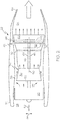
- an aircraft 20 includes a pair of turbine engines 22, 24, which are configured as turbofan engines configured to provide propulsion for the aircraft 20.
- the aircraft 20 also includes a turbine engine 26, which in this embodiment is configured as a part of an APU.
- turbine engines 22, 24, 26 are used with the aircraft 20, various other engine environments, as well as different types of turbine machinery will benefit from the features described herein.
- no particular feature or characteristic is constrained to an aircraft or to a particular application of a turbine, and the principles are equally embodied in other vehicles or in other equipment and in other applications.
- the aircraft 20 is powered by the engines 22, 24, which may provide a motive force and/or may provide electrical and hydraulic power generation. Additionally, the engines 22, 24, 26 may supply high pressure and/or high temperature air to various other components and system of the aircraft 20, if desired. As illustrated, the engines 22, 24 are coupled with the aircraft 20 on opposite sides of the fuselage. In other embodiments, other mounting positions may be used.
- the turbine engines 22, 24 provide propulsion for the aircraft 20.
- the turbine engine 26 provides energy for an environmental control system of the aircraft 20, electrical power for various purposes, and may provide other functions.
- the turbine system described herein may be employed in a variety of applications, including in the engines 22, 24, 26 or other applications.
- the engine 22 will be described with reference to FIG. 2 .
- the engine 24 is similar to the engine 22.
- the engine 22 is configured as a gas turbine engine for aircraft propulsion.
- the engine 22 includes an intake 28, with a fan section 30 disposed in a fan case 32.
- the fan section 30 draws air into the engine 22, accelerates the air within the engine 22, and may assist in providing propulsion for the aircraft 20.
- the air is directed through two paths, a core flow into the engine core 34, and a bypass through a bypass duct 36.
- a compressor section 38 compresses the air delivered to the engine core 34 and sends it to a combustion section 40.
- the air is mixed with fuel and ignited for combustion.
- Combustion air is directed into a turbine section 42, which may include single or plural turbine stages.
- the hot, high-speed air flows within the turbine case 44 and over the turbine rotor blades 46, 66 which spin on shafts 48, 64 about an axis 50.
- the axis 50 defines an axial direction 52, with a radial direction 54 projecting from the axis 50 and normal thereto.
- the air from the turbine section 42 rejoins that from the bypass duct 36 and is discharged through an exhaust section 54 including through a propulsion nozzle 56.
- the turbine section 42 includes one or more turbine stages.
- the turbine section 42 includes two turbine stages, a high-pressure turbine 58, and a power turbine 60.
- the engine 22 may be configured with a different number of turbine stages.
- the turbines 58, 60 rotate, their rotor blades 46, 66 drive equipment in the engine 22 via a two-spool arrangement with concentrically disposed shafts 48, 64.
- the high-pressure turbine rotor blades 46 drive the compressor 38 via a high-pressure spool including the shaft 48
- the power turbine rotor blades 66 drive the fan 30 via a low-pressure spool including a shaft 64.
- the high-pressure turbine 58 includes a turbine nozzle 70 upstream from the rotor blades 46 and the power turbine 60 includes a turbine nozzle 72 upstream from the rotor blades 66.
- the turbine nozzle 70 and/or the turbine nozzle 72 may include a variable device for varying flow area as described below.
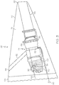
- the engine 26 involves a gas turbine APU 74, as illustrated in FIGS. 3-4 .
- the tail cone 76 area of the aircraft 20 defines a compartment that houses the APU 74.
- the APU 74 generally includes the turbine engine 26 which powers the APU 74.
- the APU 74 includes a starter 77 for starting the engine 26, a gearbox 78 for driving various loads including a generator 80 for supplying electrical power, a power compressor 82 for supplying air to a turbine section 84 through a combustor 86, and an exhaust duct 88 for delivering exhaust out of the tail 90 of the aircraft 20.
- the compressor 82 receives outside air from an inlet duct 92 that extends between the APU 74 and an inlet opening 94.
- the compressor 82 delivers, such as through a bleed system, compressed air for pneumatic powered systems 98 of the aircraft 20 through a supply duct 100. Gas in the form of air is compressed by the compressor 82 and delivered for separate uses including by the combustor 86 and by the systems 98.
- the compressor 82 may be supplied with return pressurized air through a duct 102 from the aircraft cabin 104 and/or from other uses. The return air supplied back to the engine 26 generally varies in flow rate during operation of the aircraft 20.
- the compressor 82 includes an impeller 106.
- the compressor 82 raises the pressure and temperature of air and supplies compressed air via a diffuser 107.
- the compressor 82 is a single-stage, high-pressure ratio centrifugal compressor.
- the compressed air from the compressor 82 is directed into the combustor 86, where it is mixed with fuel supplied from a fuel source (not shown).
- the fuel/air mixture is combusted at constant pressure, generating high-energy combustion gas with an increased temperature.
- the high-energy gas is supplied to the turbine section 84 through turbine nozzles 108, 110.
- the high-energy gas from the combustor 86 expands through the turbine section 84, where it gives up energy in the form of temperature and pressure and causes the turbine rotors 112, 114 to rotate.
- the gas is then exhausted from the APU 74.
- the turbine rotors 112, 114 rotate, they drive, via a turbine shaft 118, various types of equipment that may be mounted in, or coupled to, the engine 26.
- the shaft 118 drives the compressor impeller 106.
- the turbine may also be used to drive the generator 80 of FIG. 3 and/or other rotational equipment.
- the turbine nozzle 108 includes a VATN assembly 120 and the turbine nozzle 110 includes a VATN assembly 122 providing variable area turbine nozzles for varying its flow area as further described below.
- the described embodiments generally address flow and pressure ratio mis-match, control exhaust gas temperature rise, provide for high-altitude APU starting, and provide other benefits.
- these and other objectives are accomplished through the inclusion of a number of features including a variable area turbine nozzle (VATN) system for the turbine nozzles 70, 72, 108 and/or 110 including in high performance axial flow applications.
- VATN variable area turbine nozzle
- the VATN system may be applied to any or to multiple stages of the engines 22, 24, 26 or other applications.
- a VATN system 130 is applied to a first stage turbine rotor 112 of the engine 26 as an example. It should be understood that the VATN system 130 may be used with a single stage turbine, and in any number of stages in a multiple stage or spool turbine, such as with two stages as shown in FIG. 4 .
- the VATN system 130 includes a number of vanes 134 disposed in the turbine nozzle 136 upstream from the turbine rotor 132 in this embodiment. Plural vanes 134 are illustrated in FIGS. 6-7 , where it can be seen that the turbine nozzle 136 extends around the engine 126 and forms an annular flow passage for the combustion gas flow 138.
- the airfoil 140 is supported at its outer end 148 by a round-shaped support 150 that is recessed into an opening 152 in the housing section 164 and is configured to rotate therein.
- a gas path seal 154 resides in a groove in the housing section 164 and contacts the support 150 at its outer perimeter 160 to seal the combustion gas 138 in the turbine nozzle 136.
- a stem 162 extends through and out of the housing section 164 with a stem seal 166 positioned between the stem 162 and the housing 164.
- the VATN system 130 includes a drive system 170 configured to rotate the vanes 134 in unison to position them at various angles relative to the combusting gas flow 138.
- a stem gear 172 is disposed on the stem 162 outside the housing section 164.
- a spring 174 is disposed on the stem 162 and engages the stem gear 172.
- the spring 174 which may be grounded on the turbine case 44 ( FIG. 2 ), maintains minimum ID flow path gap, including zero gap, to minimize leakage.
- each spring 174 provides damping to its respective vane assembly to minimize wear (such as stem and stem gear fretting).
- a ring gear 176 includes axial facing gear surface 178 and radially outward facing gear surface 180.
- each of the plural vanes in the VATN system 130 includes a respective stem gear 172 meshing with the gear surface 178.
- the gears 172, 178, 180, 182 in the drive system 170 includes fine-toothed gears to accommodate a high rotation angle of approximately ninety-degrees between the open and closed states of FIGS. 6 and 7 .
- the drive gear 182 is mounted on the shaft of an electric motor 184 which provides high torque to overcome the friction of the tight seals 154, 166 and a near-zero clearance low leakage design.
- actuation of the drive gear 182 may be provided by hydraulic, pneumatic, mechanical, or other actuation means.
- the VATN system 130 may be integrated into a hybrid propulsion system 190.
- a generator 192 which in some embodiments may be the generator 80 of FIG. 3 , is driven by the engine and charges a battery system 194.
- the battery system 194 may be used to drive one or more fan(s) / propeller(s) 196, which in some embodiments may be the fan 30 of FIG. 2 .
- a controller 198 FIG. 6 ) controls operation of the hybrid propulsion system 190 and the VATN system 130.
- the power turbine VATN system is modulated open ( FIG. 6 ) with altitude to increase the pressure ratio (PR) of the high pressure turbine (HPT).
- PR pressure ratio
- HPT overall pressure ratio
- the VATN is fully open ( FIG. 6 ) on the ground to accommodate the increased core flow requirement at ground level running conditions and is modulated closed ( FIG. 7 ) at altitude to match the significantly reduced core flow from the cabin return.
- the VATN system 130 extends PR and operational capabilities by moving the maximum operating pressure of the engine.
- a T-S (temperature-entropy) diagram of the gas turbine cycle is shown to represent aspects of the extended performance of the embodiments described herein.
- the engine stations are represented as 0 which designates free stream air conditions
- 1 represents the engine inlet
- 2-3 represent the compressor where temperature and pressure are increased
- 3-4 represent the combustor where temperature is increased at constant pressure
- 4-5 represent the turbine where temperature and pressure drop
- 5-8 represent post turbine stages including exhaust through exhaust nozzle.
- the combustor pressure P 3 and the external pressure P 0 define the PR of the engine.
- varying the vanes 134 of the VATN system 130 changes the combustor pressure P 3 and therefore changes the PR P 3 /P 0 .
- closing the vanes 134 increases P 3 (202) which increases the PR.
- Opening the vanes 134 decreases P 3 (204) which reduces PR.
- the engine 22, 24, 26 operates as a number of different engines that are matched to different operational needs as described herein.
- engine efficiency is increased by increasing the pressure ratio.
- Increasing P 3 also increases T 4.1 and so T 4.1 and exhaust gas temperatures may be reduced by modulating the vanes 134 open, which increases core flow.
- the areas of the turbine nozzles 70, 72, 108, 110 as set by the VATN system 130 influence the total mass flow rate through the engine 22, 24, 26.
- Advanced turbine engines may be used in applications such as hybrid propulsion and integrated full-time APUs. The turbines for such applications may face increasing demands in terms of operational range.
- hybrid propulsion engines may be used in applications such as hybrid propulsion and integrated full-time APUs. The turbines for such applications may face increasing demands in terms of operational range.
- hybrid propulsion engines may face increasing demands in terms of operational range.
- the VATN system 130 is modulated to increase an engine's OPR when the T 4.1 limit is reached allowing further increases of core flow to increase power.
- FIG. 9 depicts turbine PR for a two-spool engine configuration with a HPT and a PT and with the VATN assembly located on the inlet nozzle to the PT.
- the PR of the HPT is represented by the curve 206 and the PR of the PT is represented by the curve 208.
- the curves 206 and 208 coincide at the baseline point 207 (e.g. where each produces its baseline quantity).
- Altitude is variable and is represented by the curve 209.
- the data represents engine operating conditions where the HP-turbine inlet temperature, the engine shaft power output and the PT speed are held constant
- Increasing T 4.1 may be accomplished by modulating a VATN assembly on the HPT closed. Closing the VATN on the HPT, for example VATN assembly increases the PR on the HPT (and as a consequence the PR across the PT is reduced).
- PR may also be influenced. For example, while running at a constant spool speed and constant turbine inlet temperature, increasing the turbine nozzle area by modulating open the VATN system 130, results in flow and power increases. Alternatively, opening the vanes 134 increases the flow while T 4.1 may be reduced to maintain the same output power. Lower T4.1 enables benefits such as extending time on wing.
- APUs may be fully integrated with the aircraft and provide energy for the environmental control system and electrical power both on the ground and while in flight.
- APUs may be fully integrated with the aircraft and provide energy for the environmental control system and electrical power both on the ground and while in flight.
- the design challenges of flow mis-match and turbine pressure ratio mis-match are overcome in the embodiments described herein.
- an approach to actively control the rise in exhaust gas temperature to extend the life of thermally exposed parts is provided, as is high altitude APU starting capability without increasing volume of the combustor, which avoids added weight.
- the required flow by the APU to produce the power to start the engine (22, 24) may be larger than what it would normally receive when it is fed by the cabin return flow.
- the potential flow mismatch would otherwise require having an oversized engine 26 in the APU 74 to accommodate just the main engine start requirement.
- the current embodiments enable adjusting the flow requirement of the engine 26 by modulating the vanes 134 to meet the changing operational requirements (open for main engine start and closing when in cabin pressurization mode).
- the VATN system 130 extends turbine efficiency over a wider pressure ratio operating range by adjusting the work levels between stages. A higher pressure drop through a stage will result in more work being done in that stage.
- a VATN system 130 applied to one stage may be modulated closed to increase the work done at the other stage.
- the vanes 134 in the two stages may be modulated separately to vary the amount of work done by the two stages.
- the VATN system 130 enables extending the time-on-wing of the APU by compensating for an otherwise deterioration (reflected in increased fuel flow, increased T 4.1 , and exhaust gas temperature (EGT)), by providing more engine core flow by modulating the VATN open.
- the VATN system 130 may be paired with a compressor that has extended flow range. The compressor operation line may be reset to higher flow (i.e. towards choke) at a nearly constant PR as the VATN system 130 is modulated open. The higher core flow mitigates the rise in T 4.1 /EGT at constant engine power output.
- FIG. 10 plots are shown of normalized quantities relative to a baseline at 1.00 versus normalized nozzle area of the modulated VATN system 130, relative to a baseline position.
- FIG. 10 depicts turbine PR for a two stage turbine with a HPT and a PT.
- the data represents constant altitude conditions with the VATN on the inlet nozzle to the PT, such as the VATN assembly 122 in the nozzle 110 arranged in a two-spool configuration.
- the PR of the HPT is represented by the curve 210 and the PR of the PT is represented by the curve 212.
- the core flow is represented by the curve 214.
- the curves 210 and 212 and 214 coincide at the baseline point 214 (e.g. each produces its baseline quantity).
- the PT has been found to have excess PR with altitude as the exhaust back-pressure drops. Accordingly, the VATN system 130 provides a means of adjusting the PRs as described above between the HPT and PT, to increase HPT PR. This has been found to result in the ability to extend the altitude capability of the engine, or provide the same power at reduced T 4.1 at the same altitude.
- the VATN system 130 is located in the HPT inlet nozzle, such as the VATN assembly 120 in a nozzle of an engine arranged in a two spool configuration.
- maintaining constant output power and closing the VATN system 130 such as by moving the vanes 134 in a closing direction enables increasing altitude while maintaining the same HP turbine inlet temperature.
- the VATN system 130 enhances starting capability, especially high altitude restarts by reducing the combustor loading parameter Phi.
- Phi is proportional to the mass flow through the combustor and inversely proportional to the product of the combustor volume and the pressure in the combustor to the power of 1.75.
- the VATN is modulated in general, to increase the flow through the engine and to lower the HP turbine inlet temperature T 4.1 while maintaining the power output (such as to drive a generator, propeller, etc.).
- the VATN is modulated, in general, to increase flow through the engine while maintaining the HP turbine inlet temperature T 4.1 , leading to an increase in power output. This excess in power can be used to increase the altitude at which the engine operates.
Abstract
Description
- The present invention generally relates to turbine systems and methods, and more particularly relates to a variable area turbine nozzle for improved high-altitude performance, starting capability, and extended time-on-wing.
- Turbines are used in a wide range of applications as power sources. A gas turbine engine may be used to power various types of vehicles and systems. In aircraft applications, turbines are typically used to provide propulsion for powering flight and also as an auxiliary power unit (APU). Gas turbine engines typically include a compressor that receives and compresses incoming gas such as air that is received through an inlet; a combustor in which the compressed gas is mixed with fuel and burned to produce high-pressure, high-temperature gas; and one or more turbines that extract energy from the gas exiting the combustor, which is exhausted after powering the turbines.
- A propulsion engine propels a vehicle such as an aircraft by producing thrust via exiting exhaust gases and/or powers a propeller or fan by a shaft connected with the turbine. The shaft may be used in other applications to provide a variety of functions including driving a helicopter rotor or powering rotating equipment such as a generator. For example, an APU generates compressed air and electric power for supply to various systems, such as those of an aircraft, for purposes such as environmental cooling, lighting, powering electronic systems, and main engine starting. Typically, APUs are located in the aft section of the aircraft such as the tail cone. An APU powered by a gas turbine, includes a compressor stage for supplying pressurized combustion air and a turbine stage that is driven by gases from a combustor.
- Demands on turbine engines in various application may vary significantly. For example, in hybrid propulsion applications where a combination of electrical battery power and turboshaft engine power is used, the amount of power delivered by the turbine changes depending on the amount of battery power used. Also for example, during operation, the amount of power required in applications such as an APU changes significantly. Rapid changes in demand may result in surge. In a surge condition, the air exiting the compressor reverses direction, surging back into the compressor. Accordingly, control mechanisms are employed to manage the fluctuations. Prior systems control surge by e.g., providing mid-compressor bleed during rapid acceleration to minimize aerodynamic mis-match within the compressor and compressor back pressure rise due to rapid fuel addition in the combustor. This bleed system requires complex manifolds, large piping and large bleed valve(s) resulting in large weight penalties.
- Accordingly, it is desirable to provide power turbine systems capable of extreme operating range and methods for operating the system to achieve required operational capabilities. It is also desirable to provide an effective system in a cost-effective manner with maximized time between maintenance requirements. Furthermore, other desirable features and characteristics of the present invention will become apparent from the subsequent detailed description of the invention and the appended claims, taken in conjunction with the accompanying drawings and this background of the invention.
- This summary is provided to describe select concepts in a simplified form that are further described in the Detailed Description section hereof. This summary is not intended to identify key or essential features of the claimed subject matter, nor is it intended to be used as an aid in determining the scope of the claimed subject matter.
- In a number of embodiments, a gas turbine engine includes a compressor supplying compressed air. A combustor receives the compressed air and fuel and generates a flow of combusted gas. A turbine receives a core flow of the combusted gas to rotate a turbine rotor. A turbine inlet nozzle directs the combusted gas to the turbine rotor. Vanes are disposed in the turbine inlet nozzle and rotate to vary a flow area through which the core flow passes. The vanes adjust a pressure ratio of the gas turbine engine to compensate for changing operational requirements of the gas turbine engine by rotating to positions matching the changing operational requirements.
- In other embodiments, a method is provided for operating a gas turbine engine that includes a compressor, a combustor and a turbine supplied with combustion gas from the combustor through a turbine inlet nozzle. The method includes positioning a number of vanes in the turbine inlet nozzle. The vanes are rotated to vary a flow area through which the core flow passes. A pressure ratio of the gas turbine engine is adjusted to compensate for changing operational requirements of the gas turbine engine by rotating the vanes to a position matching the changing operational requirements.
- In additional embodiments, a gas turbine engine includes a compressor having an air inlet and a compressed air outlet. The compressor is operable to increase temperature and pressure and to supply compressed air. A combustor is configured to receive at least a portion of the compressed air and a flow of fuel, and to generate a flow of combusted gas at a constant pressure. A turbine is coupled to receive a core flow of the combusted gas from the combustor to rotate a turbine rotor while temperature and pressure decrease. The core flow may be axially directed. A turbine inlet nozzle is disposed between the combustor and the turbine rotor and is configured to direct the combusted gas to the turbine rotor. A number of vanes are disposed in the turbine inlet nozzle. The vanes are configured to rotate to vary a flow area through which the core flow passes to reach the turbine rotor. A stem is connected with each of the vanes. A stem gear is disposed on each stem. A ring gear meshes with each stem gear and extends around the turbine. A drive gear meshes with the ring gear. An actuator is configured to rotate the drive gear. The vanes are configured to adjust a pressure ratio of the gas turbine engine to compensate for changing operational requirements of the gas turbine engine by rotating to a position matching the changing operational requirements.
- The present invention will hereinafter be described in conjunction with the following drawing figures, wherein like numerals denote like elements, and wherein:
-
FIG. 1 is a perspective view of an aircraft with turbine propulsion engines and an auxiliary power unit according to an exemplary embodiment; -
FIG. 2 is a cross-sectional, schematic illustration of a partial propulsion engine assembly of the aircraft ofFIG. 1 according to the exemplary embodiment; -
FIG. 3 is a cross-sectional illustration of the tail cone area of the aircraft ofFIG. 1 including the auxiliary power unit, according to an exemplary embodiment; -
FIG. 4 is cross-sectional illustration of part of the engine of the auxiliary power unit ofFIG. 3 , according to an exemplary embodiment; -
FIG. 5 is a schematic, longitudinal cross-sectional illustration of the turbine area of an engine, according to an exemplary embodiment. -
FIG. 6 is a schematic, transverse cross-sectional illustration of the turbine nozzle vane area of an engine in a first state, according to an exemplary embodiment; -
FIG. 7 is a schematic, transverse cross-sectional illustration of the turbine nozzle vane area of an engine in a second state, according to an exemplary embodiment; -
FIG. 8 is a representative diagram of temperature (T) versus entropy (S) for an engine, according to an exemplary embodiment; -
FIG. 9 is a plot of normalized quantities versus normalized nozzle area of a modulated VATN system operated at constant turbine inlet temperature, according to an exemplary embodiment; and -
FIG. 10 is a plot of normalized quantities versus normalized nozzle area of a modulated VATN system operated at constant altitude, according to an exemplary embodiment. - The following detailed description is merely exemplary in nature and is not intended to limit the invention or the application and uses of the invention. As used herein, the word "exemplary" means "serving as an example, instance, or illustration." Thus, any embodiment described herein as "exemplary" is not necessarily to be construed as preferred or advantageous over other embodiments. All of the embodiments described herein are exemplary embodiments provided to enable persons skilled in the art to make or use the invention and not to limit the scope of the invention which is defined by the claims. Furthermore, there is no intention to be bound by any expressed or implied theory presented in the preceding technical field, background, brief summary, or the following detailed description.
- In the following description, an improved turbine nozzle system and methods of operating the turbine system are provided. In the examples given herein, a turbine may be associated with a specific engine, but the disclosure is not limited in application to such engines but rather may be applied to any turbine where improved or extended performance is desired.
- In an example of the present disclosure as further described below, a gas turbine engine includes a compressor operable to supply compressed air. The compressor increases temperature and pressure of the air that it compresses. A combustor is configured to receive at least a portion of the compressed air and a flow of fuel, and to generate a flow of combusted gas. The combusted gas has a temperature higher that that leaving the compressor, while the pressure remains essentially constant through the combustor. A turbine is coupled to receive an axially directed core flow (flow may be directed radially in case of a radial turbine), of the combusted gas from the combustor to rotate a turbine rotor. Temperature and pressure of the combusted gas drops through the turbine. A turbine nozzle is disposed upstream from the turbine rotor and is configured to direct the combusted gas to the turbine rotor. A number of vanes are disposed in the turbine nozzle and the vanes are configured to vary a flow area through which the core flow passes. Opening and closing the vanes adjusts the pressure ratio of the engine to compensate for changing flow and turbine inlet requirements of the gas turbine engine. For example, while maintaining constant power output in a single spool gas turbine engine, moving the vanes in a closing direction increases the pressure-ratio of the core flow in the engine, reduces of the core flow, and requires an increase in turbine inlet temperature to maintain the same power output of the engine. Also for example, while maintaining the same power, moving the vanes in an opening direction lowers the pressure-ratio, increases the core flow and allows for a lower turbine inlet temperature of the core flow. The result is one engine that operates like multiple engines of different sizes, which is advantageous by enabling operationally matching of the engine to changing operating conditions.
- In an exemplary embodiment as illustrated in
FIG. 1 , anaircraft 20 includes a pair ofturbine engines aircraft 20. Theaircraft 20 also includes aturbine engine 26, which in this embodiment is configured as a part of an APU. Although described in the context of theaircraft 20, various features and characteristics disclosed herein may be used in other contexts and applications where turbines, or turbine engines are used. For example, although theengines aircraft 20, various other engine environments, as well as different types of turbine machinery will benefit from the features described herein. Thus, no particular feature or characteristic is constrained to an aircraft or to a particular application of a turbine, and the principles are equally embodied in other vehicles or in other equipment and in other applications. - In the current embodiment, the
aircraft 20 is powered by theengines engines aircraft 20, if desired. As illustrated, theengines aircraft 20 on opposite sides of the fuselage. In other embodiments, other mounting positions may be used. Theturbine engines aircraft 20. Theturbine engine 26 provides energy for an environmental control system of theaircraft 20, electrical power for various purposes, and may provide other functions. - As noted above, the turbine system described herein may be employed in a variety of applications, including in the
engines engine 22 will be described with reference toFIG. 2 . It should be understood that theengine 24 is similar to theengine 22. As illustrated inFIG. 2 , theengine 22 is configured as a gas turbine engine for aircraft propulsion. Theengine 22 includes anintake 28, with afan section 30 disposed in afan case 32. Thefan section 30 draws air into theengine 22, accelerates the air within theengine 22, and may assist in providing propulsion for theaircraft 20. The air is directed through two paths, a core flow into theengine core 34, and a bypass through abypass duct 36. Acompressor section 38 compresses the air delivered to theengine core 34 and sends it to acombustion section 40. In thecombustion section 40 the air is mixed with fuel and ignited for combustion. Combustion air is directed into aturbine section 42, which may include single or plural turbine stages. The hot, high-speed air flows within theturbine case 44 and over theturbine rotor blades shafts axis 50. Theaxis 50 defines anaxial direction 52, with aradial direction 54 projecting from theaxis 50 and normal thereto. The air from theturbine section 42 rejoins that from thebypass duct 36 and is discharged through anexhaust section 54 including through apropulsion nozzle 56. - The
turbine section 42 includes one or more turbine stages. In the depicted embodiment, theturbine section 42 includes two turbine stages, a high-pressure turbine 58, and apower turbine 60. However, it will be appreciated that theengine 22 may be configured with a different number of turbine stages. As theturbines 58, 60 rotate, theirrotor blades engine 22 via a two-spool arrangement with concentrically disposedshafts turbine rotor blades 46 drive thecompressor 38 via a high-pressure spool including theshaft 48, and the powerturbine rotor blades 66 drive thefan 30 via a low-pressure spool including ashaft 64. The high-pressure turbine 58 includes aturbine nozzle 70 upstream from therotor blades 46 and thepower turbine 60 includes aturbine nozzle 72 upstream from therotor blades 66. Theturbine nozzle 70 and/or theturbine nozzle 72 may include a variable device for varying flow area as described below. - By way of another exemplary embodiment, the
engine 26 involves agas turbine APU 74, as illustrated inFIGS. 3-4 . As shown inFIG. 3 , thetail cone 76 area of theaircraft 20 defines a compartment that houses theAPU 74. TheAPU 74 generally includes theturbine engine 26 which powers theAPU 74. TheAPU 74 includes astarter 77 for starting theengine 26, agearbox 78 for driving various loads including agenerator 80 for supplying electrical power, apower compressor 82 for supplying air to aturbine section 84 through acombustor 86, and anexhaust duct 88 for delivering exhaust out of thetail 90 of theaircraft 20. Thecompressor 82 receives outside air from aninlet duct 92 that extends between theAPU 74 and aninlet opening 94. In addition to supplying a main flow of combustion air to drive theturbine section 84, thecompressor 82 delivers, such as through a bleed system, compressed air for pneumaticpowered systems 98 of theaircraft 20 through asupply duct 100. Gas in the form of air is compressed by thecompressor 82 and delivered for separate uses including by thecombustor 86 and by thesystems 98. Thecompressor 82 may be supplied with return pressurized air through aduct 102 from theaircraft cabin 104 and/or from other uses. The return air supplied back to theengine 26 generally varies in flow rate during operation of theaircraft 20. - In the exemplary embodiment of the
APU 74 as illustrated inFIG. 4 , a cross section view of a portion of theengine 26 is shown. Thecompressor 82, includes an impeller 106. Thecompressor 82 raises the pressure and temperature of air and supplies compressed air via adiffuser 107. In the depicted embodiment, thecompressor 82 is a single-stage, high-pressure ratio centrifugal compressor. However, it will be appreciated that this is merely exemplary embodiment, and that other types of compressors may also be used. The compressed air from thecompressor 82 is directed into thecombustor 86, where it is mixed with fuel supplied from a fuel source (not shown). In thecombustor 86 the fuel/air mixture is combusted at constant pressure, generating high-energy combustion gas with an increased temperature. The high-energy gas is supplied to theturbine section 84 throughturbine nozzles - The high-energy gas from the
combustor 86 expands through theturbine section 84, where it gives up energy in the form of temperature and pressure and causes theturbine rotors 112, 114 to rotate. The gas is then exhausted from theAPU 74. As theturbine rotors 112, 114 rotate, they drive, via aturbine shaft 118, various types of equipment that may be mounted in, or coupled to, theengine 26. For example, in the depicted embodiment theshaft 118 drives the compressor impeller 106. It will be appreciated that the turbine may also be used to drive thegenerator 80 ofFIG. 3 and/or other rotational equipment. In the current example, theturbine nozzle 108 includes aVATN assembly 120 and theturbine nozzle 110 includes aVATN assembly 122 providing variable area turbine nozzles for varying its flow area as further described below. - Referring to
FIGS. 5-8 the described embodiments generally address flow and pressure ratio mis-match, control exhaust gas temperature rise, provide for high-altitude APU starting, and provide other benefits. In the current embodiments, these and other objectives are accomplished through the inclusion of a number of features including a variable area turbine nozzle (VATN) system for theturbine nozzles engines - As shown in
FIG. 5 , aVATN system 130 is applied to a firststage turbine rotor 112 of theengine 26 as an example. It should be understood that theVATN system 130 may be used with a single stage turbine, and in any number of stages in a multiple stage or spool turbine, such as with two stages as shown inFIG. 4 . TheVATN system 130 includes a number ofvanes 134 disposed in theturbine nozzle 136 upstream from theturbine rotor 132 in this embodiment.Plural vanes 134 are illustrated inFIGS. 6-7 , where it can be seen that theturbine nozzle 136 extends around theengine 126 and forms an annular flow passage for thecombustion gas flow 138. Eachvane 134 includes anairfoil 140 disposed in theturbine nozzle 136 that is shaped to permit unobstructed flow when open as shown inFIG. 6 and to increasingly restrict air flow when moved toward a closed position as shown inFIG. 7 where thevanes 134 are partially closed. Eachairfoil 140 is supported at itsinner end 142 by ashaft 144 that extends into thehousing section 146 and is free to rotate therein. The endwall of thehousing section 146 and ID section ofvane 134 have a spherical shape to prevent leakage flow when the vane is rotated. In some embodiments, thevane 134 may be supported by a single pin such as with no pin at the hub (bottom as viewed). Theairfoil 140 is supported at itsouter end 148 by a round-shapedsupport 150 that is recessed into anopening 152 in thehousing section 164 and is configured to rotate therein. Agas path seal 154 resides in a groove in thehousing section 164 and contacts thesupport 150 at itsouter perimeter 160 to seal thecombustion gas 138 in theturbine nozzle 136. Astem 162 extends through and out of thehousing section 164 with astem seal 166 positioned between thestem 162 and thehousing 164. - The
VATN system 130 includes adrive system 170 configured to rotate thevanes 134 in unison to position them at various angles relative to the combustinggas flow 138. Astem gear 172 is disposed on thestem 162 outside thehousing section 164. Aspring 174 is disposed on thestem 162 and engages thestem gear 172. Thespring 174, which may be grounded on the turbine case 44 (FIG. 2 ), maintains minimum ID flow path gap, including zero gap, to minimize leakage. In addition, eachspring 174 provides damping to its respective vane assembly to minimize wear (such as stem and stem gear fretting). Aring gear 176 includes axial facinggear surface 178 and radially outward facinggear surface 180. Thegear surface 178 meshes with thestem gear 172 and thegear surface 180 meshes with adrive gear 182. It should be understood that each of the plural vanes in theVATN system 130 includes arespective stem gear 172 meshing with thegear surface 178. Thegears drive system 170 includes fine-toothed gears to accommodate a high rotation angle of approximately ninety-degrees between the open and closed states ofFIGS. 6 and 7 . Thedrive gear 182 is mounted on the shaft of anelectric motor 184 which provides high torque to overcome the friction of thetight seals drive gear 182 may be provided by hydraulic, pneumatic, mechanical, or other actuation means. - As shown in
FIG. 6 , theVATN system 130 may be integrated into ahybrid propulsion system 190. Agenerator 192, which in some embodiments may be thegenerator 80 ofFIG. 3 , is driven by the engine and charges abattery system 194. Thebattery system 194 may be used to drive one or more fan(s) / propeller(s) 196, which in some embodiments may be thefan 30 ofFIG. 2 . A controller 198 (FIG. 6 ) controls operation of thehybrid propulsion system 190 and theVATN system 130. In hybrid propulsion systems where flat rating of the engine power to altitude is desired, the power turbine VATN system is modulated open (FIG. 6 ) with altitude to increase the pressure ratio (PR) of the high pressure turbine (HPT). The rise in PR leads to an increase in speed of the high pressure spool as well as overall pressure ratio (OPR), which increases the core flow and the available margin to maximum turbine inlet temperature (T4.1). - In an integrated, full-time APU application, the VATN is fully open (
FIG. 6 ) on the ground to accommodate the increased core flow requirement at ground level running conditions and is modulated closed (FIG. 7 ) at altitude to match the significantly reduced core flow from the cabin return. - The
VATN system 130 extends PR and operational capabilities by moving the maximum operating pressure of the engine. For example, as shown inFIG. 8 , a T-S (temperature-entropy) diagram of the gas turbine cycle is shown to represent aspects of the extended performance of the embodiments described herein. In the T-S diagram the engine stations are represented as 0 which designates free stream air conditions, 1 represents the engine inlet, 2-3 represent the compressor where temperature and pressure are increased, 3-4 represent the combustor where temperature is increased at constant pressure, 4-5 represent the turbine where temperature and pressure drop, and 5-8 represent post turbine stages including exhaust through exhaust nozzle. The combustor pressure P3 and the external pressure P0 define the PR of the engine. In a single spool engine with the VATN upstream of the turbine, varying thevanes 134 of theVATN system 130, changes the combustor pressure P3 and therefore changes the PR P3/P0. For example, closing thevanes 134 increases P3 (202) which increases the PR. Opening thevanes 134, decreases P3 (204) which reduces PR. Accordingly, theengine vanes 134 open, which increases core flow. - As noted, in the embodiments described herein, the areas of the
turbine nozzles VATN system 130 influence the total mass flow rate through theengine - (combined electric and gas turbine system) require extreme flat rating from sea level to high altitude, where engine power output is kept constant. It has been found that this is accomplished by providing a VATN engine that operates as different sized engines operated with power output reduced at ground level, then maintaining constant power in climb by increasing the high-pressure turbine T4.1 to boost core flow, shaft-speed, and the OPR of the engine. This compensates for density drop with altitude to minimize core flow drop until T4.1 reaches the engine's rated maximum condition. Once maximum T4.1 is reached, the HPT power to drive the compressor reduces with higher altitude. With conventional fixed turbine nozzle geometry, the HPT PR stays relatively constant throughout its operating range. According to various embodiments, the
VATN system 130 is modulated to increase an engine's OPR when the T4.1 limit is reached allowing further increases of core flow to increase power. - By way of additional explanation, reference is directed to
FIG. 9 , where plots are shown of normalized quantities relative to a baseline at 1.00 versus normalized nozzle area of the modulatedVATN system 130 relative to a baseline position at 1.00. For example, theVATN system 130 is positioned at a baseline position at 1.00 on the horizontal axis and produces quantities on the vertical axis of 1.00 at that baseline position. The baseline may be selected for typical operating conditions of the associated engine. TheVATN system 130 is open more than the baseline position to the right of 1.00 and is closed more than the baseline position to the left of 1.00.FIG. 9 depicts turbine PR for a two-spool engine configuration with a HPT and a PT and with the VATN assembly located on the inlet nozzle to the PT. The PR of the HPT is represented by thecurve 206 and the PR of the PT is represented by thecurve 208. Thecurves curve 209. The data represents engine operating conditions where the HP-turbine inlet temperature, the engine shaft power output and the PT speed are held constant - When modulating the VATN at the PT open, there is a point where the flow increase by further opening the VATN is not significant enough to make up for the reduction in PR across the PT so that the net power output can no longer be either increased or maintained without increasing T4.1. Increasing T4.1 may be accomplished by modulating a VATN assembly on the HPT closed. Closing the VATN on the HPT, for example VATN assembly increases the PR on the HPT (and as a consequence the PR across the PT is reduced).
- In embodiments for one spool engine applications with the
VATN system 130 upstream of the single turbine, PR may also be influenced. For example, while running at a constant spool speed and constant turbine inlet temperature, increasing the turbine nozzle area by modulating open theVATN system 130, results in flow and power increases. Alternatively, opening thevanes 134 increases the flow while T4.1 may be reduced to maintain the same output power. Lower T4.1 enables benefits such as extending time on wing. - Also for example, APUs may be fully integrated with the aircraft and provide energy for the environmental control system and electrical power both on the ground and while in flight. When operating in this manner, the design challenges of flow mis-match and turbine pressure ratio mis-match are overcome in the embodiments described herein. In addition, an approach to actively control the rise in exhaust gas temperature to extend the life of thermally exposed parts is provided, as is high altitude APU starting capability without increasing volume of the combustor, which avoids added weight.
- Regarding flow mis-match in the full-time APU application (where the APU is fed only by cabin return flow from the ECS during the flight), for starting of the main engine (22, 24) with operating condition of the
APU 74 being on the ground, the required flow by the APU to produce the power to start the engine (22, 24) may be larger than what it would normally receive when it is fed by the cabin return flow. The potential flow mismatch would otherwise require having anoversized engine 26 in theAPU 74 to accommodate just the main engine start requirement. However, through use of theVATN system 130, the current embodiments enable adjusting the flow requirement of theengine 26 by modulating thevanes 134 to meet the changing operational requirements (open for main engine start and closing when in cabin pressurization mode). - Regarding turbine pressure ratio mismatch, maintaining desirable power at high altitudes where the air density is significantly lower than on the ground is challenging without using an oversized engine. One option would involve the re-use of pressurized air from the
aircraft cabin 104 outflow to supercharge theengine compressor 82. While supercharging may keep the engine inlet pressure nearly constant through the flight envelope, the power turbine exhaust pressure decreases dramatically as the aircraft gains in altitude due to the lower pressure ambient conditions. Consequently, the power turbine operating PR increases by approximately a factor of two from operating the aircraft at sea level to operating the aircraft at an altitude of 41,000 feet. This may result in loss of turbine efficiency due to choked flow conditions in the power turbine. Through use of theVATN system 130 to operate an engine as if it were different sized engines to match operational requirements by varying the VATN to modulate the PR, the loss of turbine efficiency is avoided. - Through the embodiments described herein, the
VATN system 130 extends turbine efficiency over a wider pressure ratio operating range by adjusting the work levels between stages. A higher pressure drop through a stage will result in more work being done in that stage. For example, with a HPT and a PT, aVATN system 130 applied to one stage may be modulated closed to increase the work done at the other stage. In other embodiments, with aVATN system 130 applied to both stages, thevanes 134 in the two stages may be modulated separately to vary the amount of work done by the two stages. - In a number of embodiments, the
VATN system 130 enables extending the time-on-wing of the APU by compensating for an otherwise deterioration (reflected in increased fuel flow, increased T4.1, and exhaust gas temperature (EGT)), by providing more engine core flow by modulating the VATN open. In some embodiments, theVATN system 130 may be paired with a compressor that has extended flow range. The compressor operation line may be reset to higher flow (i.e. towards choke) at a nearly constant PR as theVATN system 130 is modulated open. The higher core flow mitigates the rise in T4.1/EGT at constant engine power output. - Referring to
FIG. 10 , plots are shown of normalized quantities relative to a baseline at 1.00 versus normalized nozzle area of the modulatedVATN system 130, relative to a baseline position.FIG. 10 depicts turbine PR for a two stage turbine with a HPT and a PT. The data represents constant altitude conditions with the VATN on the inlet nozzle to the PT, such as theVATN assembly 122 in thenozzle 110 arranged in a two-spool configuration. The PR of the HPT is represented by thecurve 210 and the PR of the PT is represented by thecurve 212. The core flow is represented by thecurve 214. Thecurves VATN system 130 is opened, such as by moving thevanes 134 in an opening direction, PR of the PT is decreased as demonstrated by thecurve 212, while PR of the HPT is increased as demonstrated bycurve 210. Core flow and HPT speed will also increase due to the increased PR. While keeping the engine output power constant, the increase in core flow allows for a reduction in T41, therefore extending the time on wing. - In embodiments with multiple spool engines, the PT has been found to have excess PR with altitude as the exhaust back-pressure drops. Accordingly, the
VATN system 130 provides a means of adjusting the PRs as described above between the HPT and PT, to increase HPT PR. This has been found to result in the ability to extend the altitude capability of the engine, or provide the same power at reduced T4.1 at the same altitude. Take, for example, an embodiment where theVATN system 130 is located in the HPT inlet nozzle, such as theVATN assembly 120 in a nozzle of an engine arranged in a two spool configuration. In this example when the VATN is located upstream of the HP turbine, maintaining constant output power and closing theVATN system 130 such as by moving thevanes 134 in a closing direction enables increasing altitude while maintaining the same HP turbine inlet temperature. - The
VATN system 130 enhances starting capability, especially high altitude restarts by reducing the combustor loading parameter Phi. Phi is proportional to the mass flow through the combustor and inversely proportional to the product of the combustor volume and the pressure in the combustor to the power of 1.75. With theVATN system 130 fully closed (beyond the state ofFIG. 7 ), the air flow during the initial spool-up builds pressure in the combustor chamber while the air mass flow rate in the combustor is at near-zero levels, with the effect of reducing the loading parameter Phi to conditions that are ideal for starting. Moreover, theVATN system 130 enables reducing combustor volume to minimize weight and the installation envelope. - In applications where extended time on wing is desirable, the VATN is modulated in general, to increase the flow through the engine and to lower the HP turbine inlet temperature T4.1 while maintaining the power output (such as to drive a generator, propeller, etc.). In hybrid propulsion applications, to increase the altitude at which the engine operates, the VATN is modulated, in general, to increase flow through the engine while maintaining the HP turbine inlet temperature T4.1, leading to an increase in power output. This excess in power can be used to increase the altitude at which the engine operates.
- While at least one exemplary embodiment has been presented in the foregoing detailed description of the invention, it should be appreciated that a vast number of variations exist. It should also be appreciated that the exemplary embodiment or exemplary embodiments are only examples, and are not intended to limit the scope, applicability, or configuration of the invention in any way. Rather, the foregoing detailed description will provide those skilled in the art with a convenient road map for implementing an exemplary embodiment of the invention. It being understood that various changes may be made in the function and arrangement of elements described in an exemplary embodiment without departing from the scope of the invention as set forth in the appended claims.
Claims (15)
- A gas turbine engine comprising:a compressor configured to supply compressed air;a combustor configured to receive at least a portion of the compressed air and a flow of fuel, and to generate a flow of combusted gas;a turbine coupled to receive a core flow of the combusted gas from the combustor to rotate a turbine rotor;a turbine inlet nozzle disposed between the combustor and the turbine rotor, and configured to direct the combusted gas to the turbine rotor; anda number of vanes disposed in the turbine inlet nozzle, the vanes configured to rotate to vary a flow area through which the core flow passes;wherein the vanes are configured to adjust a pressure ratio of the gas turbine engine to compensate for changing operational requirements of the gas turbine engine by rotating to positions matching the changing operational requirements.
- The gas turbine engine of claim 1, wherein the gas turbine engine is operated at varying altitude; wherein the vanes are configured to maintain a flat rating of the gas turbine engine power to the altitude.
- The gas turbine engine of claim 1, wherein the gas turbine engine is operated at varying altitude; wherein the gas turbine engine is configured to receive a secondary flow of air from a pressurized source; wherein the vanes are configured to fully open at ground level to accommodate an increased requirement of the core flow and the vanes are modulated closed as altitude increases to match a reduction in the flow of air from the pressurized source.
- The gas turbine engine of claim 3, wherein the gas turbine engine is configured as an auxiliary power unit and the pressurized source comprises a cabin air return system of an aircraft.
- The gas turbine engine of claim 1, comprising:a second turbine rotor disposed in the turbine to receive the core flow;wherein the vanes are configured to open and to close to adjust a work level between two turbine rotors by changing a pressure drop through at least one of the turbine rotors and extending an operating pressure range of the turbine.
- The gas turbine engine of claim 1, comprising:a stem connected with each of the vanes;a stem gear on each stem;a ring gear meshing with each stem gear and extending around the turbine;a drive gear meshing with the ring gear; andan actuator configured to rotate the drive gear.
- The gas turbine engine of claim 6, comprising:a housing section defining an opening; anda support connected between each stem and each vane, wherein the support is configured to rotate in the opening.
- The gas turbine engine of claim 1, wherein the vanes are configured to increase pressure ratio of the gas turbine engine by modulating closed to increase power output of the turbine.
- The gas engine of claim 1, wherein the vanes are configured to reduce a loading parameter of the combustor by modulating to a fully closed position for starting the gas turbine engine at altitude.
- The gas turbine engine of claim 1, wherein the vanes are configured to increase the core flow by modulating open to reduce turbine inlet temperature.
- A method of operating a gas turbine engine that includes a compressor, a combustor and a turbine suppled with combustion gas from the combustor through a turbine inlet nozzle, the method comprising:positioning a number of vanes in the turbine inlet nozzle;rotating the vanes to vary a flow area through which the core flow passes; andadjusting a pressure ratio of the gas turbine engine to compensate for changing operational requirements of the gas turbine engine by rotating the vanes to a position matching the changing operational requirements.
- The method of claim 11, comprising:operating the gas turbine engine at varying altitudes;maintaining a flat rating of the gas turbine engine power while the altitude changes by increasingly opening the vanes as the altitude increases; andkeeping the core flow constant while pressure ratio of the turbine increases with increasing altitude to maintain the flat rating.
- The method of claim 11, comprising:operated the gas turbine engine at varying altitude;receiving a secondary flow of air in the gas turbine engine from a pressurized source;fully opening the vanes at ground level to accommodate an increased requirement of the core flow; andmodulating the vanes closed as altitude increases to match a reduction in the flow of air from the pressurized source.
- The method of claim 13, comprising:operating the gas turbine engine as an auxiliary power unit; anddelivering the pressurized source as an aircraft cabin air return.
- The method of claim 11, comprising:positioning a second turbine rotor in the turbine to receive the core flow; andchanging a pressure drop through at least one of the turbine rotors by rotating the vanes to adjust a work level between two turbine rotors, extending an operating pressure range of the turbine.
Applications Claiming Priority (1)
| Application Number | Priority Date | Filing Date | Title |
|---|---|---|---|
| US16/412,771 US11480111B2 (en) | 2019-05-15 | 2019-05-15 | Variable area turbine nozzle and method |
Publications (2)
| Publication Number | Publication Date |
|---|---|
| EP3739191A1 true EP3739191A1 (en) | 2020-11-18 |
| EP3739191B1 EP3739191B1 (en) | 2023-01-25 |
Family
ID=70736627
Family Applications (1)
| Application Number | Title | Priority Date | Filing Date |
|---|---|---|---|
| EP20174540.3A Active EP3739191B1 (en) | 2019-05-15 | 2020-05-13 | Variable area turbine nozzle and method |
Country Status (2)
| Country | Link |
|---|---|
| US (1) | US11480111B2 (en) |
| EP (1) | EP3739191B1 (en) |
Families Citing this family (2)
| Publication number | Priority date | Publication date | Assignee | Title |
|---|---|---|---|---|
| US11867069B2 (en) * | 2021-06-28 | 2024-01-09 | Rtx Corporation | Hybrid electric variable area turbine |
| US20230042497A1 (en) * | 2021-08-06 | 2023-02-09 | Raytheon Technologies Corporation | Energy optimization for a hybrid electric engine |
Citations (4)
| Publication number | Priority date | Publication date | Assignee | Title |
|---|---|---|---|---|
| US3060686A (en) * | 1956-06-15 | 1962-10-30 | Garrett Corp | Augmented gas turbine engine and controls |
| US20060016196A1 (en) * | 2004-07-21 | 2006-01-26 | Epstein Stanley W | Onboard supplemental power system at varying high altitudes |
| US20150176530A1 (en) * | 2013-12-19 | 2015-06-25 | United Technologies Corporation | Ultra high overall pessure ratio gas turbine engine |
| US20170036768A1 (en) * | 2015-08-07 | 2017-02-09 | Rolls-Royce Plc | Auxillary power unit assembly and a method of using the same |
Family Cites Families (39)
| Publication number | Priority date | Publication date | Assignee | Title |
|---|---|---|---|---|
| US2608054A (en) | 1942-03-06 | 1952-08-26 | Lockheed Aircraft Corp | Air turbine starting means for gas turbine power plants |
| US2411895A (en) | 1944-04-15 | 1946-12-03 | United Aircraft Corp | Nozzle control |
| US2514393A (en) * | 1947-09-03 | 1950-07-11 | Westinghouse Electric Corp | Variable area exhaust nozzle for power plants |
| US2551229A (en) | 1949-10-14 | 1951-05-01 | Gen Electric | Variable area nozzle and fluid injection control for turbojet engines |
| US2791882A (en) | 1950-09-29 | 1957-05-14 | Westinghouse Electric Corp | Variable area nozzle for jet propulsion engine |
| FR1483743A (en) * | 1965-12-02 | 1967-06-09 | Snecma | Turbomachine with contra-rotating compressor |
| GB1313841A (en) * | 1967-01-18 | 1973-04-18 | Secr Defence | Gas turbine jet propulsion engine |
| DE1963432C3 (en) * | 1969-12-18 | 1979-03-22 | Motoren- Und Turbinen-Union Muenchen Gmbh, 8000 Muenchen | Control device for a gas turbine plant |
| US3834161A (en) * | 1973-06-01 | 1974-09-10 | Us Air Force | Dual mode auxiliary power unit |
| US5079916A (en) * | 1982-11-01 | 1992-01-14 | General Electric Company | Counter rotation power turbine |
| US4759178A (en) * | 1987-03-17 | 1988-07-26 | Williams International Corporation | Aircraft auxiliary power unit |
| US4912921A (en) * | 1988-03-14 | 1990-04-03 | Sundstrand Corporation | Low speed spool emergency power extraction system |
| US4932206A (en) | 1988-08-17 | 1990-06-12 | Sundstrand Corporation | Guide vane assembly for auxiliary power unit |
| GB2301868B (en) * | 1995-06-05 | 1999-08-11 | Rolls Royce Plc | Improved actuator mechanism for variable angle vane arrays |
| GB0002257D0 (en) * | 2000-02-02 | 2000-03-22 | Rolls Royce Plc | Rotary apparatus for a gas turbine engine |
| DE10202532C1 (en) | 2002-01-24 | 2003-05-08 | Porsche Ag | Air outlet nozzle, for vehicle, has a nozzle body, and two movable flap sections moved by a common drive device having a self-locking worm gear pair connected to an actuator element for synchronous movement of the two flap sections |
| US7036321B2 (en) | 2003-10-08 | 2006-05-02 | Honeywell International, Inc. | Auxiliary power unit having a rotary fuel slinger |
| US7251942B2 (en) | 2004-06-29 | 2007-08-07 | Honeywell International Inc. | Integrated gearless and nonlubricated auxiliary power unit |
| US7937945B2 (en) * | 2006-10-27 | 2011-05-10 | Kinde Sr Ronald August | Combining a series of more efficient engines into a unit, or modular units |
| US8007229B2 (en) * | 2007-05-24 | 2011-08-30 | United Technologies Corporation | Variable area turbine vane arrangement |
| US20100260591A1 (en) * | 2007-06-08 | 2010-10-14 | General Electric Company | Spanwise split variable guide vane and related method |
| GB0713951D0 (en) | 2007-07-18 | 2007-08-29 | Cummins Turbo Tech Ltd | Calibration of an actuator for a variable geometry turbine |
| US9701415B2 (en) | 2007-08-23 | 2017-07-11 | United Technologies Corporation | Gas turbine engine with axial movable fan variable area nozzle |
| JP4838785B2 (en) * | 2007-11-06 | 2011-12-14 | 三菱重工業株式会社 | Gas turbine operation control device and operation control method |
| US8079217B2 (en) | 2008-11-24 | 2011-12-20 | Honeywell International Inc. | Turbocharger with variable turbine nozzle actuated by hydraulic and mechanical spring forces |
| US20110176913A1 (en) * | 2010-01-19 | 2011-07-21 | Stephen Paul Wassynger | Non-linear asymmetric variable guide vane schedule |
| FR2976018B1 (en) | 2011-06-01 | 2014-12-05 | Turbomeca | VARIABLE TIMING RADIAL TURBINE DISPENSER, ESPECIALLY AUXILIARY POWER SOURCE TURBINE |
| US8291690B1 (en) * | 2012-01-31 | 2012-10-23 | United Technologies Corporation | Gas turbine engine with variable area fan nozzle positioned for starting |
| US9957832B2 (en) * | 2012-02-28 | 2018-05-01 | United Technologies Corporation | Variable area turbine |
| US8862362B2 (en) | 2012-07-02 | 2014-10-14 | United Technologies Corporation | Scheduling of variable area fan nozzle to optimize engine performance |
| US10378550B2 (en) | 2012-12-18 | 2019-08-13 | Korea Aerospace Research Institute | Apparatus for preventing axial-flow compressor from stalling by employing casing treatment |
| WO2015048238A1 (en) | 2013-09-30 | 2015-04-02 | Borgwarner Inc. | Actuating mechanism and gear driven adjustment ring for a variable geometry turbocharger |
| US9863367B2 (en) | 2013-11-01 | 2018-01-09 | The Boeing Company | Fan nozzle drive systems that lock thrust reversers |
| US10012102B2 (en) * | 2014-02-21 | 2018-07-03 | United Technologies Corporation | Variable vane synchronization ring transmission mechanism |
| GB201407314D0 (en) * | 2014-04-25 | 2014-06-11 | Rolls Royce Plc | Control of a gas turbine engine |
| US10294813B2 (en) * | 2016-03-24 | 2019-05-21 | United Technologies Corporation | Geared unison ring for variable vane actuation |
| GB2558228B (en) * | 2016-12-22 | 2020-05-20 | Rolls Royce Plc | Aircraft electrically-assisted propulsion control system |
| US10208675B2 (en) | 2017-03-15 | 2019-02-19 | The Boeing Company | Hybrid drive system for transferring power from a gas turbine engine of an aircraft |
| US10981660B2 (en) * | 2018-04-19 | 2021-04-20 | The Boeing Company | Hybrid propulsion engines for aircraft |
-
2019
- 2019-05-15 US US16/412,771 patent/US11480111B2/en active Active
-
2020
- 2020-05-13 EP EP20174540.3A patent/EP3739191B1/en active Active
Patent Citations (4)
| Publication number | Priority date | Publication date | Assignee | Title |
|---|---|---|---|---|
| US3060686A (en) * | 1956-06-15 | 1962-10-30 | Garrett Corp | Augmented gas turbine engine and controls |
| US20060016196A1 (en) * | 2004-07-21 | 2006-01-26 | Epstein Stanley W | Onboard supplemental power system at varying high altitudes |
| US20150176530A1 (en) * | 2013-12-19 | 2015-06-25 | United Technologies Corporation | Ultra high overall pessure ratio gas turbine engine |
| US20170036768A1 (en) * | 2015-08-07 | 2017-02-09 | Rolls-Royce Plc | Auxillary power unit assembly and a method of using the same |
Also Published As
| Publication number | Publication date |
|---|---|
| US11480111B2 (en) | 2022-10-25 |
| EP3739191B1 (en) | 2023-01-25 |
| US20200362768A1 (en) | 2020-11-19 |
Similar Documents
| Publication | Publication Date | Title |
|---|---|---|
| US20200309027A1 (en) | Gas turbine engine with an electromagnetic transmission | |
| CN108137162B (en) | Auxiliary power unit with variable speed ratio | |
| EP2584173B1 (en) | Gas Turbine Engine | |
| EP1574689B1 (en) | Methods and apparatus for operating gas turbine engines | |
| US8978352B2 (en) | Apparatus and method for operating a gas turbine engine during windmilling | |
| US7059136B2 (en) | Air turbine powered accessory | |
| US8117827B2 (en) | Apparatus for operating gas turbine engines | |
| US11873766B2 (en) | Differential geared amplification of auxiliary power unit | |
| US6968674B2 (en) | Methods and apparatus for operating gas turbine engines | |
| US8966876B2 (en) | Controllable speed windmill operation of a gas turbine engine through low spool power extraction | |
| US20140147278A1 (en) | Variable-pitch nozzle for a radial turbine, in particular for an auxiliary power source turbine | |
| EP3739191B1 (en) | Variable area turbine nozzle and method | |
| US11015476B2 (en) | Electrical energy generating system | |
| US10859003B2 (en) | Control system for a gas turbine engine | |
| US11965458B2 (en) | Multi-mode engine system with gas turbine engine and turbo-compressor | |
| EP4187069A1 (en) | Multi-mode engine system with gas turbine engine and turbo-compressor | |
| US11339717B2 (en) | Environmental control system | |
| US20230296058A1 (en) | Systems and methods for starting a gas turbine engine | |
| CN115451427A (en) | Interstage combustion chamber and turbofan engine with same | |
| CN112302808A (en) | Active stability control of compression systems using electric motors |
Legal Events
| Date | Code | Title | Description |
|---|---|---|---|
| PUAI | Public reference made under article 153(3) epc to a published international application that has entered the european phase |
Free format text: ORIGINAL CODE: 0009012 |
|
| STAA | Information on the status of an ep patent application or granted ep patent |
Free format text: STATUS: THE APPLICATION HAS BEEN PUBLISHED |
|
| AK | Designated contracting states |
Kind code of ref document: A1 Designated state(s): AL AT BE BG CH CY CZ DE DK EE ES FI FR GB GR HR HU IE IS IT LI LT LU LV MC MK MT NL NO PL PT RO RS SE SI SK SM TR |
|
| AX | Request for extension of the european patent |
Extension state: BA ME |
|
| STAA | Information on the status of an ep patent application or granted ep patent |
Free format text: STATUS: REQUEST FOR EXAMINATION WAS MADE |
|
| 17P | Request for examination filed |
Effective date: 20210324 |
|
| RBV | Designated contracting states (corrected) |
Designated state(s): AL AT BE BG CH CY CZ DE DK EE ES FI FR GB GR HR HU IE IS IT LI LT LU LV MC MK MT NL NO PL PT RO RS SE SI SK SM TR |
|
| RAP3 | Party data changed (applicant data changed or rights of an application transferred) |
Owner name: HONEYWELL INTERNATIONAL INC. |
|
| RIC1 | Information provided on ipc code assigned before grant |
Ipc: F02C 9/54 20060101ALI20220722BHEP Ipc: F02C 9/22 20060101AFI20220722BHEP |
|
| GRAP | Despatch of communication of intention to grant a patent |
Free format text: ORIGINAL CODE: EPIDOSNIGR1 |
|
| STAA | Information on the status of an ep patent application or granted ep patent |
Free format text: STATUS: GRANT OF PATENT IS INTENDED |
|
| INTG | Intention to grant announced |
Effective date: 20220906 |
|
| GRAS | Grant fee paid |
Free format text: ORIGINAL CODE: EPIDOSNIGR3 |
|
| GRAA | (expected) grant |
Free format text: ORIGINAL CODE: 0009210 |
|
| STAA | Information on the status of an ep patent application or granted ep patent |
Free format text: STATUS: THE PATENT HAS BEEN GRANTED |
|
| AK | Designated contracting states |
Kind code of ref document: B1 Designated state(s): AL AT BE BG CH CY CZ DE DK EE ES FI FR GB GR HR HU IE IS IT LI LT LU LV MC MK MT NL NO PL PT RO RS SE SI SK SM TR |
|
| REG | Reference to a national code |
Ref country code: GB Ref legal event code: FG4D |
|
| REG | Reference to a national code |
Ref country code: CH Ref legal event code: EP |
|
| REG | Reference to a national code |
Ref country code: AT Ref legal event code: REF Ref document number: 1546066 Country of ref document: AT Kind code of ref document: T Effective date: 20230215 Ref country code: IE Ref legal event code: FG4D |
|
| REG | Reference to a national code |
Ref country code: DE Ref legal event code: R096 Ref document number: 602020007770 Country of ref document: DE |
|
| REG | Reference to a national code |
Ref country code: LT Ref legal event code: MG9D |
|
| REG | Reference to a national code |
Ref country code: NL Ref legal event code: MP Effective date: 20230125 |
|
| P01 | Opt-out of the competence of the unified patent court (upc) registered |
Effective date: 20230421 |
|
| REG | Reference to a national code |
Ref country code: AT Ref legal event code: MK05 Ref document number: 1546066 Country of ref document: AT Kind code of ref document: T Effective date: 20230125 |
|
| PG25 | Lapsed in a contracting state [announced via postgrant information from national office to epo] |
Ref country code: NL Free format text: LAPSE BECAUSE OF FAILURE TO SUBMIT A TRANSLATION OF THE DESCRIPTION OR TO PAY THE FEE WITHIN THE PRESCRIBED TIME-LIMIT Effective date: 20230125 |
|
| PG25 | Lapsed in a contracting state [announced via postgrant information from national office to epo] |
Ref country code: RS Free format text: LAPSE BECAUSE OF FAILURE TO SUBMIT A TRANSLATION OF THE DESCRIPTION OR TO PAY THE FEE WITHIN THE PRESCRIBED TIME-LIMIT Effective date: 20230125 Ref country code: PT Free format text: LAPSE BECAUSE OF FAILURE TO SUBMIT A TRANSLATION OF THE DESCRIPTION OR TO PAY THE FEE WITHIN THE PRESCRIBED TIME-LIMIT Effective date: 20230525 Ref country code: NO Free format text: LAPSE BECAUSE OF FAILURE TO SUBMIT A TRANSLATION OF THE DESCRIPTION OR TO PAY THE FEE WITHIN THE PRESCRIBED TIME-LIMIT Effective date: 20230425 Ref country code: LV Free format text: LAPSE BECAUSE OF FAILURE TO SUBMIT A TRANSLATION OF THE DESCRIPTION OR TO PAY THE FEE WITHIN THE PRESCRIBED TIME-LIMIT Effective date: 20230125 Ref country code: LT Free format text: LAPSE BECAUSE OF FAILURE TO SUBMIT A TRANSLATION OF THE DESCRIPTION OR TO PAY THE FEE WITHIN THE PRESCRIBED TIME-LIMIT Effective date: 20230125 Ref country code: HR Free format text: LAPSE BECAUSE OF FAILURE TO SUBMIT A TRANSLATION OF THE DESCRIPTION OR TO PAY THE FEE WITHIN THE PRESCRIBED TIME-LIMIT Effective date: 20230125 Ref country code: ES Free format text: LAPSE BECAUSE OF FAILURE TO SUBMIT A TRANSLATION OF THE DESCRIPTION OR TO PAY THE FEE WITHIN THE PRESCRIBED TIME-LIMIT Effective date: 20230125 Ref country code: AT Free format text: LAPSE BECAUSE OF FAILURE TO SUBMIT A TRANSLATION OF THE DESCRIPTION OR TO PAY THE FEE WITHIN THE PRESCRIBED TIME-LIMIT Effective date: 20230125 |
|
| PGFP | Annual fee paid to national office [announced via postgrant information from national office to epo] |
Ref country code: FR Payment date: 20230523 Year of fee payment: 4 |
|
| PG25 | Lapsed in a contracting state [announced via postgrant information from national office to epo] |
Ref country code: SE Free format text: LAPSE BECAUSE OF FAILURE TO SUBMIT A TRANSLATION OF THE DESCRIPTION OR TO PAY THE FEE WITHIN THE PRESCRIBED TIME-LIMIT Effective date: 20230125 Ref country code: PL Free format text: LAPSE BECAUSE OF FAILURE TO SUBMIT A TRANSLATION OF THE DESCRIPTION OR TO PAY THE FEE WITHIN THE PRESCRIBED TIME-LIMIT Effective date: 20230125 Ref country code: IS Free format text: LAPSE BECAUSE OF FAILURE TO SUBMIT A TRANSLATION OF THE DESCRIPTION OR TO PAY THE FEE WITHIN THE PRESCRIBED TIME-LIMIT Effective date: 20230525 Ref country code: GR Free format text: LAPSE BECAUSE OF FAILURE TO SUBMIT A TRANSLATION OF THE DESCRIPTION OR TO PAY THE FEE WITHIN THE PRESCRIBED TIME-LIMIT Effective date: 20230426 Ref country code: FI Free format text: LAPSE BECAUSE OF FAILURE TO SUBMIT A TRANSLATION OF THE DESCRIPTION OR TO PAY THE FEE WITHIN THE PRESCRIBED TIME-LIMIT Effective date: 20230125 |
|
| REG | Reference to a national code |
Ref country code: DE Ref legal event code: R097 Ref document number: 602020007770 Country of ref document: DE |
|
| PG25 | Lapsed in a contracting state [announced via postgrant information from national office to epo] |
Ref country code: SM Free format text: LAPSE BECAUSE OF FAILURE TO SUBMIT A TRANSLATION OF THE DESCRIPTION OR TO PAY THE FEE WITHIN THE PRESCRIBED TIME-LIMIT Effective date: 20230125 Ref country code: RO Free format text: LAPSE BECAUSE OF FAILURE TO SUBMIT A TRANSLATION OF THE DESCRIPTION OR TO PAY THE FEE WITHIN THE PRESCRIBED TIME-LIMIT Effective date: 20230125 Ref country code: EE Free format text: LAPSE BECAUSE OF FAILURE TO SUBMIT A TRANSLATION OF THE DESCRIPTION OR TO PAY THE FEE WITHIN THE PRESCRIBED TIME-LIMIT Effective date: 20230125 Ref country code: DK Free format text: LAPSE BECAUSE OF FAILURE TO SUBMIT A TRANSLATION OF THE DESCRIPTION OR TO PAY THE FEE WITHIN THE PRESCRIBED TIME-LIMIT Effective date: 20230125 Ref country code: CZ Free format text: LAPSE BECAUSE OF FAILURE TO SUBMIT A TRANSLATION OF THE DESCRIPTION OR TO PAY THE FEE WITHIN THE PRESCRIBED TIME-LIMIT Effective date: 20230125 |
|
| PG25 | Lapsed in a contracting state [announced via postgrant information from national office to epo] |
Ref country code: SK Free format text: LAPSE BECAUSE OF FAILURE TO SUBMIT A TRANSLATION OF THE DESCRIPTION OR TO PAY THE FEE WITHIN THE PRESCRIBED TIME-LIMIT Effective date: 20230125 |
|
| PLBE | No opposition filed within time limit |
Free format text: ORIGINAL CODE: 0009261 |
|
| REG | Reference to a national code |
Ref country code: DE Ref legal event code: R119 Ref document number: 602020007770 Country of ref document: DE |
|
| STAA | Information on the status of an ep patent application or granted ep patent |
Free format text: STATUS: NO OPPOSITION FILED WITHIN TIME LIMIT |
|
| REG | Reference to a national code |
Ref country code: CH Ref legal event code: PL |
|
| 26N | No opposition filed |
Effective date: 20231026 |
|
| PG25 | Lapsed in a contracting state [announced via postgrant information from national office to epo] |
Ref country code: MC Free format text: LAPSE BECAUSE OF FAILURE TO SUBMIT A TRANSLATION OF THE DESCRIPTION OR TO PAY THE FEE WITHIN THE PRESCRIBED TIME-LIMIT Effective date: 20230125 |
|
| REG | Reference to a national code |
Ref country code: BE Ref legal event code: MM Effective date: 20230531 |
|
| PG25 | Lapsed in a contracting state [announced via postgrant information from national office to epo] |
Ref country code: SI Free format text: LAPSE BECAUSE OF FAILURE TO SUBMIT A TRANSLATION OF THE DESCRIPTION OR TO PAY THE FEE WITHIN THE PRESCRIBED TIME-LIMIT Effective date: 20230125 Ref country code: MC Free format text: LAPSE BECAUSE OF FAILURE TO SUBMIT A TRANSLATION OF THE DESCRIPTION OR TO PAY THE FEE WITHIN THE PRESCRIBED TIME-LIMIT Effective date: 20230125 Ref country code: LU Free format text: LAPSE BECAUSE OF NON-PAYMENT OF DUE FEES Effective date: 20230513 Ref country code: LI Free format text: LAPSE BECAUSE OF NON-PAYMENT OF DUE FEES Effective date: 20230531 Ref country code: CH Free format text: LAPSE BECAUSE OF NON-PAYMENT OF DUE FEES Effective date: 20230531 |
|
| REG | Reference to a national code |
Ref country code: IE Ref legal event code: MM4A |
|
| PG25 | Lapsed in a contracting state [announced via postgrant information from national office to epo] |
Ref country code: IE Free format text: LAPSE BECAUSE OF NON-PAYMENT OF DUE FEES Effective date: 20230513 |