EP3739156A1 - Hold open device and door assembly - Google Patents
Hold open device and door assembly Download PDFInfo
- Publication number
- EP3739156A1 EP3739156A1 EP19174481.2A EP19174481A EP3739156A1 EP 3739156 A1 EP3739156 A1 EP 3739156A1 EP 19174481 A EP19174481 A EP 19174481A EP 3739156 A1 EP3739156 A1 EP 3739156A1
- Authority
- EP
- European Patent Office
- Prior art keywords
- hold open
- guide
- open device
- door
- cavity
- Prior art date
- Legal status (The legal status is an assumption and is not a legal conclusion. Google has not performed a legal analysis and makes no representation as to the accuracy of the status listed.)
- Withdrawn
Links
- 239000006096 absorbing agent Substances 0.000 claims abstract description 21
- 238000000034 method Methods 0.000 description 7
- 230000014759 maintenance of location Effects 0.000 description 3
- 238000013459 approach Methods 0.000 description 2
- 230000001419 dependent effect Effects 0.000 description 1
- 238000009795 derivation Methods 0.000 description 1
- 238000012986 modification Methods 0.000 description 1
- 230000004048 modification Effects 0.000 description 1
- 230000007704 transition Effects 0.000 description 1
Images


Classifications
-
- E—FIXED CONSTRUCTIONS
- E05—LOCKS; KEYS; WINDOW OR DOOR FITTINGS; SAFES
- E05C—BOLTS OR FASTENING DEVICES FOR WINGS, SPECIALLY FOR DOORS OR WINDOWS
- E05C17/00—Devices for holding wings open; Devices for limiting opening of wings or for holding wings open by a movable member extending between frame and wing; Braking devices, stops or buffers, combined therewith
- E05C17/02—Devices for holding wings open; Devices for limiting opening of wings or for holding wings open by a movable member extending between frame and wing; Braking devices, stops or buffers, combined therewith by mechanical means
- E05C17/04—Devices for holding wings open; Devices for limiting opening of wings or for holding wings open by a movable member extending between frame and wing; Braking devices, stops or buffers, combined therewith by mechanical means with a movable bar or equivalent member extending between frame and wing
- E05C17/12—Devices for holding wings open; Devices for limiting opening of wings or for holding wings open by a movable member extending between frame and wing; Braking devices, stops or buffers, combined therewith by mechanical means with a movable bar or equivalent member extending between frame and wing consisting of a single rod
- E05C17/24—Devices for holding wings open; Devices for limiting opening of wings or for holding wings open by a movable member extending between frame and wing; Braking devices, stops or buffers, combined therewith by mechanical means with a movable bar or equivalent member extending between frame and wing consisting of a single rod pivoted at one end, and with the other end running along a guide member
- E05C17/28—Devices for holding wings open; Devices for limiting opening of wings or for holding wings open by a movable member extending between frame and wing; Braking devices, stops or buffers, combined therewith by mechanical means with a movable bar or equivalent member extending between frame and wing consisting of a single rod pivoted at one end, and with the other end running along a guide member with braking, clamping or securing means at the connection to the guide member
Definitions
- This invention is related to the field of door closing systems, e. g., those used in doors of residential or commercial buildings, and more particularly, to the devices which are in charge of providing a hold open functionality to those systems.
- Automated door closing systems are used to make a door close automatically when it has been opened. These systems are usually based on a spring which stores energy when the door is being opened and exerts a return force to close the door.
- Some extra functionalities are often provided with these door closers.
- the ability to keep the door open in a predetermined angle is often required by some manufacturers.
- This functionality is often provided by a device which retains an element which is associated with the door bar.
- Document US 5,461,754 A discloses a door closer comprising a detent and a slide element.
- the slide element slides along a guide until contacting the detent.
- the detent comprises retention means to hold the slide element in position, thus holding the door open.
- the retention force is overcome by tugging the door.
- the invention provides an alternative solution for providing a hold open functionality by a hold open device according to claim 1 and a door assembly according to claim 9.
- Preferred embodiments of the invention are defined in dependent claims.
- the invention provides a hold open device for a door assembly, the hold open device comprising
- the sliding element is intended to slide along the guide while the door is being open or closed.
- the detent retains the engaging element of the sliding element in its cavity.
- the absorber element advantageously dampens the movement of the engaging element, so that it enters the cavity softly. This lessens the tugging force to get the door closed again and also the noise caused by this disengagement.
- the detent comprises a ramp configured to guide the engaging element from the guide towards the cavity.
- This ramp makes the movement of reaching the cavity easier, so there is no sudden force to apply when the sliding element reaches the cavity.
- the engaging element is a pin comprising a pin axis perpendicular to the sliding direction and substantially perpendicularly to the first direction.
- a pin is an advantageous element to match with a cavity.
- a transverse pin as comprised in these embodiments provides a smooth sliding movement, may be easily biased and provides a suitable surface to be kept in the cavity. The relation between the diameter of the pin and the size of the cavity may be tuned for a finer choice of the device behaviour.
- the sliding element comprises a guide slot for the pin, the guide slot being configured to guide the pin when biased by the biasing element.
- This guide slot limits the movement of the pin, so that it may not be pushed out of control by the biasing element.
- the absorber element comprises a cantilever portion attached to a fixed body, so that the reaction force is provided by the elastic flexion of the cantilever portion.
- This cantilever portion may be designed to provide a tailored reaction force, which is chosen as a function of the biasing force, also taking into account the features required by the door manufacturer.
- the cavity comprises a main slot and at least a portion of the absorber element is introduced in the main slot.
- the position of at least a portion of the absorber element between two portions of the cavity improves the stability of the engaging element when introduced in the cavity.
- the absorber element comprises a spring which provides the reaction force.
- This spring may be also chosen to provided the required reaction force.
- the biasing element of the sliding element is a leaf spring crossed by a bolt.
- a leaf spring is a good option for this element, since it takes little room in the biasing direction, and a very fine biasing force choice is not usually required.
- the invention provides a door assembly comprising
- the door of this door assembly may be hold open in a predetermined position and then be closed again avoiding unpleasant noises and with an easily modulated tugging force.
- FIG. 1 shows a first embodiment of a door assembly 10 according to the invention.
- This door assembly 10 comprises
- the hold open device 1 is in charge of providing some hold open functionality to the door 12.
- the hold open device comprises, as seen in this figure, a guide 2 and a sliding element 4 which is arranged to slide along the guide 2 according to a sliding direction sd.
- This sliding element 4 is pivotally attached to the door arm 13 so that when the door 12 opens and closes, the door arm 13 joins a point of the door 12 with the sliding element 4. Since the position of this point changes while the door turns, and the door arm 13 has a fixed length, the sliding element 4 is forced to slide along the guide 2 to meet the boundary conditions.
- the guide 2 is arranged in the door frame 11 to keep the hold open device 1 as concealed as possible.
- the hold open device also comprises a detent 3 which is attached to the guide 2 and provides a stable position for the sliding element 4 corresponding to a predetermined opening angle of the door 12. When the sliding element 4 reaches the detent 3, it may be kept in this position if the door is set free.
- Figure 2 shows a detailed description of a sliding element 4 belonging to the hold open device 1 seen in the previous figure.
- This sliding element 4 comprises a pin 5 and a biasing element 6, which in this case comprises a leaf spring crossed by a bolt.
- This biasing element 6 is arranged to bias the pin 5 with a biasing force according to a first direction d.
- the pin 5 comprises a pin axis a which is perpendicular to the sliding direction sd and substantially perpendicularly to the first direction d. It is thus arranged transversally to the sliding direction.
- the sliding element 4 comprises a guide slot 41 for the pin 5, thus providing a vertical guidance for the pin 5, so that it may move along the guide slot 41 when is biased by the biasing element 6.
- the biasing element 6 pushes the pin 5 upwards, so that the pin slides in contact with the upper wall of the guide.
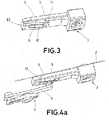
- Figure 3 shows a detailed description of a detent 3 belonging to the hold open device 1 seen in figure 1 .
- This detent 3 comprises a cavity 7, an absorber element 8 and a ramp 9.
- the cavity 7 is configured to house at least a portion of the pin.
- the pin first encounters the ramp 9. This ramp 9 is intended to guide the pin towards the cavity 7.
- the absorber element 8 comprises a cantilever portion 81 attached to a fixed body 82.
- the cantilever portion 81 is introduced inside a main slot 71 in the middle of the cavity 7, and stands out from this main slot 71. As a consequence, the cantilever portion 81 is arranged to receive the pin 5 when it arrives at the cavity 7.
- Figures 4a to 4c show different stages in the movement of the elements of the hold open device according to the invention, while a door opening process is taking place.
- Figure 4a shows a first stage in this process.
- the sliding element 4 slides along the guide 2 and approaches the ramp 9.
- the biasing element 6 will bias the pin 5 against the ramp 9.
- Figure 4b shows the next stage in this process.
- the sliding element continues towards the cavity 7, but the cantilever portion 81 of the absorber element receives the pin 5 first.
- the biasing element 6 bias the pin 5 against the cantilever portion 81 of the absorber element. This biasing force flexes the cantilever portion 81, so that the absorber element provides a reaction force in a direction opposite to the biasing force. This softens the movement of the pin 5, avoiding sudden noises.
- Figure 4c shows a final stage in this process. While the sliding element is approaching the final position in the cavity, the cantilever portion 81 flexes and allows the pin 5 to be housed in its final position inside the cavity. The pin 5 is then installed in the hold open position, and is kept in this position by the biasing force, which bias the pin 5 towards the stable position in the cavity, but it has arrived there without sudden or unpleasant noises. The tugging will be performed in a similar sense. The reaction force of the cantilever portion 81 of the absorber will help a smooth transition for the pin 5 just after exiting the cavity, so that the process of closing the door does not comprise any sudden or unpleasant noises.
Landscapes
- Engineering & Computer Science (AREA)
- Mechanical Engineering (AREA)
- Closing And Opening Devices For Wings, And Checks For Wings (AREA)
- Wing Frames And Configurations (AREA)
Abstract
The invention is related to a hold open device (1) comprising a guide (2), a detent (3) attached to the guide (2) and a sliding element (4) arranged to slide along the guide (2). The sliding element (4) comprises an engaging element (5) and a biasing element (6) arranged to bias the engaging element (5) with a biasing force according to a first direction (d). The detent (3) comprises a cavity (7) configured to house at least a portion of the engaging element (5) and further comprises an absorber element (8), the absorber element being configured to exert a reaction force when pressed, the reaction force being lower than the biasing force. The invention also comprises a door assembly (10) comprising such a hold open device (1).
Description
- This invention is related to the field of door closing systems, e. g., those used in doors of residential or commercial buildings, and more particularly, to the devices which are in charge of providing a hold open functionality to those systems.
- Automated door closing systems are used to make a door close automatically when it has been opened. These systems are usually based on a spring which stores energy when the door is being opened and exerts a return force to close the door.
- Some extra functionalities are often provided with these door closers. The ability to keep the door open in a predetermined angle is often required by some manufacturers. This functionality is often provided by a device which retains an element which is associated with the door bar.
- Document
US 5,461,754 A discloses a door closer comprising a detent and a slide element. The slide element slides along a guide until contacting the detent. The detent comprises retention means to hold the slide element in position, thus holding the door open. The retention force is overcome by tugging the door. - These systems rely on cams or springs, and the tugging movement causes a sudden and often unpleasant noise, due to the disengagement of the retention element.
- An alternative solution for this problem is therefore sought.
- The invention provides an alternative solution for providing a hold open functionality by a hold open device according to
claim 1 and a door assembly according toclaim 9. Preferred embodiments of the invention are defined in dependent claims. - Unless otherwise defined, all terms (including technical and scientific terms) used herein are to be interpreted as is customary in the art. It will be further understood that terms in common usage should also be interpreted as is customary in the relevant art and not in an idealised or overly formal sense unless expressly so defined herein.
- In this text, the term "comprises" and its derivations (such as "comprising", etc.) should not be understood in an excluding sense, that is, these terms should not be interpreted as excluding the possibility that what is described and defined may include further elements, steps, etc.
- In a first inventive aspect, the invention provides a hold open device for a door assembly, the hold open device comprising
- a guide intended to be installed in a door frame;
- a detent attached to the guide; and
- a sliding element intended to receive an end of a door arm, the sliding element being arranged to slide along the guide according to a sliding direction;
wherein - the sliding element comprises an engaging element and a biasing element arranged to bias the engaging element with a biasing force according to a first direction;
- the detent comprises a cavity configured to house at least a portion of the engaging element and further comprises an absorber element, the absorber element being configured to exert a reaction force when pressed, the reaction force being lower than the biasing force;
- the first direction is the direction to keep the engaging element in the cavity when the engaging element enters the cavity.
- The sliding element is intended to slide along the guide while the door is being open or closed. When the door reaches a predetermined opening angle, the detent retains the engaging element of the sliding element in its cavity. But to make this movement smoother, the absorber element advantageously dampens the movement of the engaging element, so that it enters the cavity softly. This lessens the tugging force to get the door closed again and also the noise caused by this disengagement.
- In some particular embodiments, the detent comprises a ramp configured to guide the engaging element from the guide towards the cavity.
- This ramp makes the movement of reaching the cavity easier, so there is no sudden force to apply when the sliding element reaches the cavity.
- In some particular embodiments, the engaging element is a pin comprising a pin axis perpendicular to the sliding direction and substantially perpendicularly to the first direction. A pin is an advantageous element to match with a cavity. A transverse pin as comprised in these embodiments provides a smooth sliding movement, may be easily biased and provides a suitable surface to be kept in the cavity. The relation between the diameter of the pin and the size of the cavity may be tuned for a finer choice of the device behaviour.
- In some particular embodiments, the sliding element comprises a guide slot for the pin, the guide slot being configured to guide the pin when biased by the biasing element.
- This guide slot limits the movement of the pin, so that it may not be pushed out of control by the biasing element.
- In some particular embodiments, the absorber element comprises a cantilever portion attached to a fixed body, so that the reaction force is provided by the elastic flexion of the cantilever portion.
- This cantilever portion may be designed to provide a tailored reaction force, which is chosen as a function of the biasing force, also taking into account the features required by the door manufacturer.
- In some particular embodiments, the cavity comprises a main slot and at least a portion of the absorber element is introduced in the main slot.
- The position of at least a portion of the absorber element between two portions of the cavity improves the stability of the engaging element when introduced in the cavity.
- In some particular embodiments, the absorber element comprises a spring which provides the reaction force.
- This spring may be also chosen to provided the required reaction force.
- In some particular embodiments, the biasing element of the sliding element is a leaf spring crossed by a bolt.
- A leaf spring is a good option for this element, since it takes little room in the biasing direction, and a very fine biasing force choice is not usually required.
- In a second inventive aspect, the invention provides a door assembly comprising
- a hold open device according to the first inventive aspect;
- a door frame, the guide being arranged in this door frame; and
- a door comprising a door arm which is pivotally attached to the sliding element.
- The door of this door assembly may be hold open in a predetermined position and then be closed again avoiding unpleasant noises and with an easily modulated tugging force.
- To complete the description and in order to provide for a better understanding of the invention, a set of drawings is provided. Said drawings form an integral part of the description and illustrate an embodiment of the invention, which should not be interpreted as restricting the scope of the invention, but just as an example of how the invention can be carried out. The drawings comprise the following figures:
-
Figure 1 shows a first embodiment of a door assembly according to the invention. -
Figure 2 shows a detailed description of a sliding element belonging to the hold open device according to the invention. -
Figure 3 shows a detailed description of a detent belonging to the hold open device according to the invention. -
Figures 4a to 4c show different stages in the movement of the elements of the hold open device according to the invention, while a door opening process is taking place. - Elements of the example embodiments are consistently denoted by the same reference numerals throughout the drawings and detailed description where appropriate:
- 1
- Hold open device
- 2
- Guide
- 3
- Detent
- 4
- Sliding element
- 41
- Guide slot
- 5
- Pin (engaging element)
- 6
- Biasing element
- 7
- Cavity
- 71
- Main slot
- 8
- Absorber element
- 81
- Cantilever portion
- 82
- Fixed body
- 9
- Ramp
- 10
- Door assembly
- 11
- Door frame
- 12
- Door
- 13
- Door arm
- a
- Axis of the pin
- d
- First direction
- sd
- Sliding direction
- The example embodiments are described in sufficient detail to enable those of ordinary skill in the art to embody and implement the systems and processes herein described. It is important to understand that embodiments can be provided in many alternate forms and should not be construed as limited to the examples set forth herein.
- Accordingly, while embodiment can be modified in various ways and take on various alternative forms, specific embodiments thereof are shown in the drawings and described in detail below as examples. There is no intent to limit to the particular forms disclosed. On the contrary, all modifications, equivalents, and alternatives falling within the scope of the appended claims should be included.
-
Figure 1 shows a first embodiment of adoor assembly 10 according to the invention. Thisdoor assembly 10 comprises - a hold
open device 1; - a
door frame 11, - a
door 12 comprising adoor arm 13. - The hold
open device 1 is in charge of providing some hold open functionality to thedoor 12. To achieve this aim, the hold open device comprises, as seen in this figure, aguide 2 and a slidingelement 4 which is arranged to slide along theguide 2 according to a sliding direction sd. This slidingelement 4 is pivotally attached to thedoor arm 13 so that when thedoor 12 opens and closes, thedoor arm 13 joins a point of thedoor 12 with the slidingelement 4. Since the position of this point changes while the door turns, and thedoor arm 13 has a fixed length, the slidingelement 4 is forced to slide along theguide 2 to meet the boundary conditions. - The
guide 2 is arranged in thedoor frame 11 to keep the holdopen device 1 as concealed as possible. - The hold open device also comprises a
detent 3 which is attached to theguide 2 and provides a stable position for the slidingelement 4 corresponding to a predetermined opening angle of thedoor 12. When the slidingelement 4 reaches thedetent 3, it may be kept in this position if the door is set free. -
Figure 2 shows a detailed description of a slidingelement 4 belonging to the holdopen device 1 seen in the previous figure. - This sliding
element 4 comprises apin 5 and abiasing element 6, which in this case comprises a leaf spring crossed by a bolt. This biasingelement 6 is arranged to bias thepin 5 with a biasing force according to a first direction d. - The
pin 5 comprises a pin axis a which is perpendicular to the sliding direction sd and substantially perpendicularly to the first direction d. It is thus arranged transversally to the sliding direction. - The sliding
element 4 comprises aguide slot 41 for thepin 5, thus providing a vertical guidance for thepin 5, so that it may move along theguide slot 41 when is biased by the biasingelement 6. - When the sliding
element 4 moves along the guide (which is not represented in this figure), the biasingelement 6 pushes thepin 5 upwards, so that the pin slides in contact with the upper wall of the guide. -
Figure 3 shows a detailed description of adetent 3 belonging to the holdopen device 1 seen infigure 1 . - This
detent 3 comprises acavity 7, anabsorber element 8 and aramp 9. - The
cavity 7 is configured to house at least a portion of the pin. When the sliding element approaches thedetent 3, the pin first encounters theramp 9. Thisramp 9 is intended to guide the pin towards thecavity 7. - The
absorber element 8 comprises acantilever portion 81 attached to a fixedbody 82. Thecantilever portion 81 is introduced inside amain slot 71 in the middle of thecavity 7, and stands out from thismain slot 71. As a consequence, thecantilever portion 81 is arranged to receive thepin 5 when it arrives at thecavity 7. -
Figures 4a to 4c show different stages in the movement of the elements of the hold open device according to the invention, while a door opening process is taking place. -
Figure 4a shows a first stage in this process. The slidingelement 4 slides along theguide 2 and approaches theramp 9. The biasingelement 6 will bias thepin 5 against theramp 9. -
Figure 4b shows the next stage in this process. The sliding element continues towards thecavity 7, but thecantilever portion 81 of the absorber element receives thepin 5 first. The biasingelement 6 bias thepin 5 against thecantilever portion 81 of the absorber element. This biasing force flexes thecantilever portion 81, so that the absorber element provides a reaction force in a direction opposite to the biasing force. This softens the movement of thepin 5, avoiding sudden noises. -
Figure 4c shows a final stage in this process. While the sliding element is approaching the final position in the cavity, thecantilever portion 81 flexes and allows thepin 5 to be housed in its final position inside the cavity. Thepin 5 is then installed in the hold open position, and is kept in this position by the biasing force, which bias thepin 5 towards the stable position in the cavity, but it has arrived there without sudden or unpleasant noises. The tugging will be performed in a similar sense. The reaction force of thecantilever portion 81 of the absorber will help a smooth transition for thepin 5 just after exiting the cavity, so that the process of closing the door does not comprise any sudden or unpleasant noises.
Claims (9)
- Hold open device (1) for a door assembly (10), the hold open device (1) comprisinga guide (2) intended to be installed in a door frame (11);a detent (3) attached to the guide (2); anda sliding element (4) intended to receive an end of a door arm, the sliding element (4) being arranged to slide along the guide (2) according to a sliding direction (sd); whereinthe sliding element (4) comprises an engaging element (5) and a biasing element (6) arranged to bias the engaging element (5) with a biasing force according to a first direction (d);the detent (3) comprises a cavity (7) configured to house at least a portion of the engaging element (5) and further comprises an absorber element (8), the absorber element being configured to exert a reaction force when pressed, the reaction force being lower than the biasing force;the first direction (d) is the direction to keep the engaging element (5) in the cavity (7) when the engaging element enters the cavity.
- Hold open device (1) according to claim 1, wherein the detent (3) comprises a ramp (9) configured to guide the engaging element (5) from the guide (2) towards the cavity (7).
- Hold open device (1) according to any of the preceding claims, wherein the engaging element (5) is a pin comprising a pin axis (a) perpendicular to the sliding direction (sd) and substantially perpendicularly to the first direction (d).
- Hold open device (1) according to claim 3, wherein the sliding element (4) comprises a guide slot (41) for the pin, the guide slot (41) being configured to guide the pin (5) when biased by the biasing element (6).
- Hold open device (1) according to any of the preceding claims, wherein the absorber element (8) comprises a cantilever portion (81) attached to a fixed body (82), so that the reaction force is provided by the elastic flexion of the cantilever portion (81).
- Hold open device (1) according to any of the preceding claims, wherein the cavity (7) comprises a main slot (71) and at least a portion of the absorber element (8) is introduced in the main slot (71).
- Hold open device (1) according to any of the preceding claims, wherein the absorber element (8) comprises a spring which provides the reaction force.
- Hold open device (1) according to any of the preceding claims, wherein the biasing element (6) of the sliding element (4) is a leaf spring crossed by a bolt.
- Door assembly (10) comprisinga hold open device (1) according to any of the preceding claims;a door frame (11), the guide (2) being arranged in this door frame (11)a door (12) comprising a door arm (13) which is pivotally attached to the sliding element (4).
Priority Applications (4)
| Application Number | Priority Date | Filing Date | Title |
|---|---|---|---|
| EP19174481.2A EP3739156A1 (en) | 2019-05-14 | 2019-05-14 | Hold open device and door assembly |
| JP2020055186A JP2020186642A (en) | 2019-05-14 | 2020-03-25 | Open state holding device and door assembly |
| CN202010251183.XA CN111946177A (en) | 2019-05-14 | 2020-04-01 | Stay open device and door assembly |
| TW109113075A TW202108865A (en) | 2019-05-14 | 2020-04-17 | Hold open device and door assembly |
Applications Claiming Priority (1)
| Application Number | Priority Date | Filing Date | Title |
|---|---|---|---|
| EP19174481.2A EP3739156A1 (en) | 2019-05-14 | 2019-05-14 | Hold open device and door assembly |
Publications (1)
| Publication Number | Publication Date |
|---|---|
| EP3739156A1 true EP3739156A1 (en) | 2020-11-18 |
Family
ID=66554184
Family Applications (1)
| Application Number | Title | Priority Date | Filing Date |
|---|---|---|---|
| EP19174481.2A Withdrawn EP3739156A1 (en) | 2019-05-14 | 2019-05-14 | Hold open device and door assembly |
Country Status (4)
| Country | Link |
|---|---|
| EP (1) | EP3739156A1 (en) |
| JP (1) | JP2020186642A (en) |
| CN (1) | CN111946177A (en) |
| TW (1) | TW202108865A (en) |
Citations (5)
| Publication number | Priority date | Publication date | Assignee | Title |
|---|---|---|---|---|
| JPH05515U (en) * | 1991-06-25 | 1993-01-08 | 東プレ株式会社 | Anti-luggage device for luggage door in van type car |
| US5446944A (en) * | 1993-10-15 | 1995-09-05 | Von Duprin, Inc. | Rocker latch overhead door holder assembly |
| US5461754A (en) | 1992-08-17 | 1995-10-31 | Dorma Gmbh + Co. Kg | Door closer with a detent for holding a door open and the detent therefor |
| DE4426430A1 (en) * | 1994-07-26 | 1996-02-01 | Geze Gmbh & Co | Electrically operated door locking method |
| DE102012104852A1 (en) * | 2012-06-05 | 2013-12-05 | Dorma Gmbh + Co. Kg | Track assembly |
-
2019
- 2019-05-14 EP EP19174481.2A patent/EP3739156A1/en not_active Withdrawn
-
2020
- 2020-03-25 JP JP2020055186A patent/JP2020186642A/en active Pending
- 2020-04-01 CN CN202010251183.XA patent/CN111946177A/en active Pending
- 2020-04-17 TW TW109113075A patent/TW202108865A/en unknown
Patent Citations (5)
| Publication number | Priority date | Publication date | Assignee | Title |
|---|---|---|---|---|
| JPH05515U (en) * | 1991-06-25 | 1993-01-08 | 東プレ株式会社 | Anti-luggage device for luggage door in van type car |
| US5461754A (en) | 1992-08-17 | 1995-10-31 | Dorma Gmbh + Co. Kg | Door closer with a detent for holding a door open and the detent therefor |
| US5446944A (en) * | 1993-10-15 | 1995-09-05 | Von Duprin, Inc. | Rocker latch overhead door holder assembly |
| DE4426430A1 (en) * | 1994-07-26 | 1996-02-01 | Geze Gmbh & Co | Electrically operated door locking method |
| DE102012104852A1 (en) * | 2012-06-05 | 2013-12-05 | Dorma Gmbh + Co. Kg | Track assembly |
Also Published As
| Publication number | Publication date |
|---|---|
| CN111946177A (en) | 2020-11-17 |
| JP2020186642A (en) | 2020-11-19 |
| TW202108865A (en) | 2021-03-01 |
Similar Documents
| Publication | Publication Date | Title |
|---|---|---|
| EP3688262B1 (en) | Improvements in movement control devices | |
| US20160168896A1 (en) | Adjusting device | |
| KR101319231B1 (en) | Door opening/closing system and catch therefor | |
| JP5019898B2 (en) | Bidirectional retract unit | |
| CN101657594B (en) | Restricting devices | |
| US20070090735A1 (en) | Drawer slide with push-latch device | |
| CN105960500B (en) | Bearing arrangement for door | |
| RU2594867C2 (en) | Hinge | |
| WO2007025077A2 (en) | Closing device for drawers | |
| EP3218565B1 (en) | A damping or return device for sliding door leaves | |
| EP1431671B1 (en) | A door hinge | |
| EP3224441B1 (en) | A damping or return device for sliding door leaves or for drawers | |
| CN112135953B (en) | Soft self-closing door damper | |
| CA2345514A1 (en) | Locking mechanism for chair and pushbutton control therefor | |
| JP5204711B2 (en) | Door closer | |
| KR101524829B1 (en) | Damping Device for Door of Furniture | |
| US20150143666A1 (en) | Closing sequence control for a double-leaf door | |
| JP2014062391A (en) | Pull-in device unit | |
| CN111373106B (en) | Roof windows with improved spring assemblies | |
| WO2017125768A1 (en) | Automatic locking mechanism | |
| CN111946177A (en) | Stay open device and door assembly | |
| CN108699875B (en) | Deployment device | |
| CN108505861B (en) | A prevent tong mechanism that turns over folding door on being used for furniture | |
| EP3696359A1 (en) | Door closer assembly | |
| EP3489445A1 (en) | Locking device, particularly hold-open device, for a door actuator assembly |
Legal Events
| Date | Code | Title | Description |
|---|---|---|---|
| PUAI | Public reference made under article 153(3) epc to a published international application that has entered the european phase |
Free format text: ORIGINAL CODE: 0009012 |
|
| STAA | Information on the status of an ep patent application or granted ep patent |
Free format text: STATUS: THE APPLICATION HAS BEEN PUBLISHED |
|
| AK | Designated contracting states |
Kind code of ref document: A1 Designated state(s): AL AT BE BG CH CY CZ DE DK EE ES FI FR GB GR HR HU IE IS IT LI LT LU LV MC MK MT NL NO PL PT RO RS SE SI SK SM TR |
|
| AX | Request for extension of the european patent |
Extension state: BA ME |
|
| STAA | Information on the status of an ep patent application or granted ep patent |
Free format text: STATUS: THE APPLICATION IS DEEMED TO BE WITHDRAWN |
|
| 18D | Application deemed to be withdrawn |
Effective date: 20210519 |